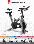
1
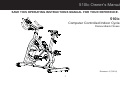
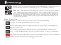
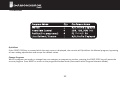
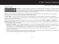
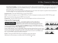
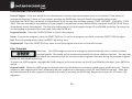
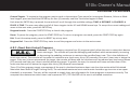
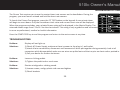
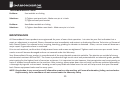
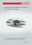
2THOUSANDTWELVE 510Ic Indoor Cycle OWNER’S MANUAL PURCHASER’S REFERENCE INFORMATION PLEASE RECORD DETAILS ASSOCIATED WITH THE PURCHASE OF YOUR 510Ic BELOW. THIS INFORMATION WILL BE REQUIRED IN THE EVENT THE UNIT REQUIRES FUTURE SERVICE. *ATTACH THE PURCHASE RECEIPT HERE: Product Name: Diamondback 510Ic Indoor Cycle Serial Number: E ___ ___ ___ ___ ___ ___ ___ ___ ___ ___ PLE SERIAL NUMBER IIII III IIIII IIIIII E0000000000 WARNING: REMOVAL SAM Date Purchased: Dealer Name: Dealer Address: Dealer Contact Name: Dealer Telephone Number: ( Serial Number Location ) To Activate Warranty: Register the unit at www.diamondbackfitness.com OR complete the attached warranty card (see last page) and return it to Diamondback Fitness within 15 days of purchase. Failure to comply may limit or void the Manufacturer’s warranty coverage. Shipping Materials: Diamondback Fitness recommends that you retain the original packing materials (box and packing items) for future shipping needs. Warranty: ____ Mailed ____ Online Date ________________ 2 510Ic Owner’s Manual SAVE THIS OPERATING INSTRUCTIONS MANUAL FOR YOUR REFERENCE. 510Ic Computer Controlled Indoor Cycle Diamondback Fitness Release v.2 (7/2011) 1 TABLE OF CONTENTS PURCHASER’S REFERENCE INFORMATION - Inside Front Cover INTRODUCTION 3 SAFETY INSTRUCTIONS & WARNINGS 4 CARTON CONTENTS 7 510Ic ASSEMBLY INSTRUCTIONS 8 WORKOUT GUIDELINES 13 WORKOUT QUALITY AND QUANTITY 17 CONSOLE OVERVIEW & GENERAL NOTES 18 CONSOLE KEYPAD FUNCTION 20 CONSOLE OPERATION AND FEATURES 21 PROGRAM CATEGORIES 23 TROUBLESHOOTING 29 MAINTENANCE 30 WARRANTY INFORMATION 31 WARRANTY REGISTRATION CARD 35 2 510Ic Owner’s Manual INTRODUCTION Congratulations on the purchase of your new 510Ic Computer-Controlled Indoor Cycle from Diamondback Fitness. You have made a smart choice and are about to enjoy one of the most effective and technically-advanced methods of cardio-vascular exercise available today. Founded in 1991 as an off-shoot of the legendary bicycle division, Diamondback Fitness was in many ways a complimentary addition to the Diamondback brand. One might even say this extension grew as a natural evolution from classic outdoor bicycle usage toward indoor-based cycling and cross training. It turns out many fitness enthusiasts were searching for ways to maintain conditioning during times of inclement weather or were simply looking for new and different crosstraining options. This trend still continues today, twenty years later, as the strong Diamondback brand resonates with both the boomers who grew up with the bicycles, as well as the younger generations riding them today. Diamondback Fitness continues to build upon this legendary brand identity by offering the cardio enthusiast a full line of upright bikes, recumbents, indoor cycles, and elliptical trainers that offer great value, high quality and intuitive & visually-pleasing design. Let’s just say, we are already planning our next twenty years. Diamondback Fitness 6004 South 190th Street Suite 101 Kent WA 98032 Ph. 1.800.776.7642 Fax: 1.800.776.2073 For more information or questions regarding your equipment, please visit our website at www.diamondbackfitness.com 3 SAFETY INSTRUCTIONS & WARNINGS Every piece of Diamondback Fitness equipment is built for maximum safety and meets or exceeds all applicable domes c and interna onal standards. However, certain precau ons must be taken when opera ng any exercise equipment. NOTE: Please read the en re owner’s manual before opera ng the 510Ic. CAUTION - FOR SAFE OPERATION • Keep your hands and feet away from all moving parts and pinch points. • If you have a history of heart disease, high blood pressure, diabetes, chronic respiratory diseases, elevated cholesterol, or if you smoke cigare es or experience any other chronic diseases or physical complaints, consult with a physician before beginning any exercise program. • If overweight, or above the age of 35, consult with your physician before beginning any exercise program. • Pregnant women should consult with their physician before beginning an exercise program. • If you experience dizziness, nausea, chest pains or other abnormal symptoms during exercise, stop the exercise session immediately and consult your physician. • Consume water before, during and a er each exercise session. 4 510Ic Owner’s Manual SAFETY INSTRUCTIONS & WARNINGS WARNINGS - TO REDUCE RISK OF INJURY TO YOURSELF OR OTHERS • To ensure proper func oning of your unit, do not install a achments or accessories not provided or recommended by Diamondback Fitness. • Always wear proper clothing and shoes when exercising. • User weight is not to exceed 300 pounds (147.4 Kg) for the 510Ic. • Keep children away from the unit. Hands and feet may become entangled with the moving parts and could result in serious injury. • Place the unit in an area that will meet minimum clearance requirements: - front & sides = 24 inches - rear = 12 inches. • The unit is intended for indoor use only. • Place the unit on a solid, level surface. Always adjust the leveling feet before using to ensure stability. • Ensure all adjustment knobs and levers are fastened securely before using the unit and a er making an adjustment. • Use the handlebars when stepping on and off the unit. • The unit is heavy. Do not a empt to move alone. • Never operate the unit if it is damaged or broken. Contact your local authorized Diamondback Fitness Dealer for service. • Always unplug the unit from the power source before moving or servicing. • Do not remove the covers or other components. Only Authorized Diamondback Fitness Dealers or Authorized Technicians should perform service on the unit. 5 SAFETY INSTRUCTIONS & WARNINGS Assembly of Technical Items Assembly of all Diamondback Fitness products should be performed by a Diamondback Fitness Dealer or Authorized Technician. A significant amount of technical knowledge is required for the safe and complete assembly of the unit. Many retailers will offer delivery and assembly as part of the sales agreement. If this unit was sold unassembled (in the carton) and you do not feel you can perform the assembly successfully, please call the dealer for service. Service calls for improper assembly are not covered by the Warranty Policy and any associated charges will be the responsibility of the owner. Assembly may include adjustment and alignment of side cases and a achment brackets as needed for proper func on. +)ODW:DVKHU W +$OOHQ%ROW03PP +)ODW:DVKHU W +6FUHZV0PP %R[6SDQQHU $OOHQ.H\ 6FUHZGULYHU $OOHQ.H\ 6 510Ic Owner’s Manual CARTON CONTENTS Parts List Item Description A A-1 B B-1 B-4 B-5 B-11 B-13 C D D-1 D-2 F-16 F (L & R) G G-1 G-2 G-6 G-9 G-13 H-1 H-2 H-3 H-4 K L L-5 M-1 N 510ICġ +)ODW:DVKHU W +$OOHQ%ROW03PP +)ODW:DVKHU W +6FUHZV0PP 6FUHZGULYHU %R[6SDQQHU $OOHQ.H\ $OOHQ.H\ 00 7 Console Console Fixing Screw Handlebar Mast Assembly Handlebar Assembly Endcap Handlebar Assembly Endcap Screw Handlebars Heart Rate Console Wire Wire Harness - Upper Rear Stabilizer Assembly Front Stabilizer Assembly Leveling Foot Assembly Leveling Foot Lock Nut Power Input Jack Pedal, Clip & Strap Assembly (pair) Main Frame Water Bottle Cage Assembly Water Bottle Stem / Seat Post Adjustment Knob Wire Harness - Lower Water Bottle Cage fixing screws Stabilizer Assembly Fixing Screw Stabilizer Assembly Curved Washer Stabilizer Assembly Flat Washer Handlebar Assembly Positioning Screw Assembly Hardware / Tool Kit Saddle Fore-Aft Adjustment Lever Emergency Stop Knob Power Supply/Adaptor Quantity 1 4 1 1 1 1 1 1 1 1 4 4 1 1 1 1 1 1 1 1 8 4 4 4 1 1 1 1 1 ASSEMBLY INSTRUCTIONS • Unpack the 510Ic from the carton. Please recycle. • Using the 6mm allen wrench, remove the blocking (the short sec on of tubing installed at the factory to prevent damage to the front frame during shipping) by removing the two fixing screws shown in Figure 1 above. • Align the front stabilizer (D) with the receiver located in the front of the frame, and loosely install four (4) H-1 bolts, two (2) curved washers (H-2) and two (2) flat washers (H-3), making sure that the correct shape of washers are installed on their corresponding surface profile; i.e. flat washer on the flat surface, etc. When all bolts have been inserted, ghten for final installa on with the 6mm allen wrench. • Discard this piece. • Repeat this process for the rear stabilizer assembly (C). • Verify the carton contains all parts from the list. 8 510Ic Owner’s Manual ASSEMBLY INSTRUCTIONS • Install the saddle (L) onto the seat post and ghten with the included wrench. • Install the handlebars by sliding the bracket up under the handlebar mast (B) Feed the Heart Rate Console Wire (B-11) through the opening under the mast and pull it up and out with the wire harness. • Install the pedals (F-L & F-R) into the crank arms. Threading the le pedal (marked with an “L”) by hand into the le crank with a counter-clockwise rota on. Do not cross-thread the cranks/pedals. The pedal must be ght and installed completely to prevent future damage to the cranks. • Posi on the Handlebars (B-5) in 1 of 3 possible posi ons depending on user preference and install the 4 (H-4) Handlebar Assembly Posi oning Screws into place and ghten with the 6mm allen wrench securing the Handlebars (B-5) to the Handlebar Mast (B). • Repeat the pedal installa on steps for the right side, no ng that the pedal will thread into the right crank with a clockwise • Make sure not to pinch the the Heart Rate Console Wire (B-11). rota on. 9 ASSEMBLY INSTRUCTIONS • Insert the handlebar/stem assembly into the receiver on the main frame, paying care not to pinch the wire harness connector (B-13). • Loosen the stem height adjuster knob (G-15) with two or three counter-clockwise rota ons. Adjust the stem/handlebar assembly to the lowest posi on by pulling outward on the knob to disengage the pop-pin. If the stem assembly does not drop, loosen the knob further and pull outward on the knob again. Repeat these steps again if necessary. • Remove the four console fixing screws (A-1) from the back of the Console (A) and set them aside. • Plug the upper wire harness connector (B-13) and the Heart Rate Console Wire (B-11) into the matching connectors on the back of the Console (A). Make sure both connec ons are firmly connected and click into posi on. • Posi on the console above the moun ng plate located on the Handlebar Mast (B). Be careful feeding excess wires into the opening on the Handlebar Mast (B) while posi oning the console. • Reinstall the four (4) fixing screws (A-1) through the underside of the plate and into the console. Tighten the four screws only a er all four have been started by hand. • Install the Water Bo le Cage (G-1) using the 2 Water Bo le Cage Assembly Screws (G-13). Insert Water Bo le (G-2) into Water Bo le Cage (G-1). 10 510Ic Owner’s Manual ASSEMBLY INSTRUCTIONS • Locate connector (B-13) exi ng the bo om of the handlebar assembly (B). • Remove handlebar assembly endcap fixing screw (B-4) from the handlebar assembly endcap (B-1). • Connect (B-13) to wire harness connector G-9, taking care to ensure the connec on is firm. • Insert the handlebar assembly endcap (B-1) into the bo om of the handlebar assembly (B). • Feed excess cable into mast. • Reinstall the handlebar assembly endcap fixing screw (B-4) through the base of the handlebar assembly (B) to secure the endcap. • Take care not to pinch wire. 11 ASSEMBLY INSTRUCTIONS FINAL INSTALLLTION & SET UP • Moving and Posi oning the Unit. Move the 510Ic into the desired final posi on by carefully raising the rear end of the unit un l the wheels located on the front stabilizer contact the floor. Leave room around the unit for safe opera on and sufficient air flow. • Leveling the Unit. Level the unit by rota ng the four leveling feet (D-1) located in the stabilizer bars. Lock the feet into posi on by ghtening the lock nut (D-2) upward, against the frame. • Final Adjustments – Up/Down. Raise and lower the seat and handlebar assemblies by loosening the adjuster knobs (G-6) with a couple of counter-clockwise rota ons. While suppor ng the assembly, pull the knob outward, away from the frame, to disengage the pop-pin. Raise or lower the assembly as desired, releasing the knob to reengage the pop pin. Tighten the knob to lock the assembly in place. • Final Adjustments – Fore/A . Fore-a adjustment for the seat is made by loosening the lever (L-5). Rotate the lever to the le to loosen. If the lever movement is inhibited by the frame or other components, pull the lever downward to reposi on the lever and release. Con nue to loosen. Only ¼ turn should be required to loosen or ghten the levers. Posi on the seat slide and secure the lever. • Plug one end of the power adaptor (N) into a 120V power source. Plug the opposite end into the power input jack (F-16) found on the rear end of the plas c housing. 12 510Ic Owner’s Manual WORKOUT GUIDELINES Good health is an exercise in common sense. In the study tled, “The Surgeon General’s Call To AcƟon To Prevent and Decrease Overweight and Obesity”, the Surgeon General indicates that 61% of American adults are either overweight or obese. The study indicates that being overweight increases the risk of health problems, such as heart disease, certain types of cancer, type 2 diabetes among other afflic ons. The Surgeon General’s Healthy weight advice for consumers is: • Aim for a healthy weight: Find your Body Mass Index (BMI) on the chart below. • Be ac ve: Keep physically ac ve to balance the calories you consume. • Eat well: Select sensible por on sizes. Body Mass Index; BMI = (weight (lb) ⍦ height² (in)) x 703 Height in Feet and Inches Weight in Pounds 120 130 140 150 160 170 180 190 200 210 220 230 240 250 4'6 29 31 34 36 39 41 43 46 48 51 53 56 58 60 4'8 27 29 31 34 36 38 40 43 45 47 49 52 54 56 4'10 25 27 29 31 34 36 38 40 42 44 46 48 50 52 5'0 23 25 27 29 31 33 35 37 39 41 43 45 47 49 5'2 22 24 26 27 29 31 33 35 37 38 40 42 44 46 5'4 21 22 24 26 28 29 31 33 34 36 38 40 41 43 5'6 19 21 23 24 26 27 29 31 32 34 36 37 39 40 5'8 18 20 21 23 24 26 27 29 30 32 34 35 37 38 5'10 17 19 20 22 23 24 26 27 29 30 32 33 35 36 6'0 16 18 19 20 22 23 24 26 27 28 30 31 33 34 6'2 15 17 18 19 21 22 23 24 26 27 28 30 31 32 6'4 15 16 17 18 20 21 22 23 24 26 27 28 29 30 6'6 14 15 16 17 19 20 21 22 23 24 25 27 28 29 6'8 13 14 15 17 18 19 20 21 22 23 24 25 26 28 Note: Chart applies to adults aged 20 years and older 13 Healthy Weight Overweight Obese WORKOUT GUILDLINES Heart rate is an important key to your exercise. The Surgeon General also released a report on physical ac vity and health. This report dictates that exercise and fitness are beneficial for a person’s health and reiterated the need for exercise as a key component of disease preven on and healthier living. If exercise intensity is too low or too high, no gains will be made in fitness. If the intensity is too low, the stress levels are ineffec ve. If the intensity is too high, injury or fa gue may set your exercise program back as you try to recover. The best way to determine exercise intensity is to accurately count your pulse during exercise. Your heart rate can easily be determined by coun ng your pulse at the chest, wrist or at the caro d artery on your neck. It is difficult to count your own pulse during exercise, mainly because you cannot count fast enough to record an accurate rate. This Diamondback Fitness 510Ic is equipped with contact heart rate sensors. 14 510Ic Owner’s Manual WORKOUT GUILDLINES Calculated Maximum Heart Rate & Target Training Zone Your calculated target heart rate, or the ideal intensity needed to improve cardiovascular fitness, depends primarily upon your age rather than your current state of fitness. If the exercise intensity is too low or too high, only modest gains will be made in strength and cardio-vascular fitness. A workout at a very low intensity will not offer maximum benefits. Conversely, if the workout intensity is too high, injury or fa gue may slow the progression of your exercise goals as the body a empts to recover. Note: It is most effec ve to train at a heart rate between 60% and 85% of your maximum heart rate. Maximum heart rate is calculated as a percentage of your maximum heart rate (es mated as 220 beats-per-minute minus your age). To calculate your maximum heart rate and find the appropriate target training zone, use the following formulas. For example, the following es ma on would be relevant for a 35 year-old user: 220 - Age = Maximum Heart Rate (220 - 35 = 185) 60% of Maximum Heart Rate (60% x 185 = 111bpm) 85% of Maximum Heart Rate (85% x 185 = 157bpm) Based on these calcula ons, the recommended heart rate training zone for this user would be between 111 Bpm – 157 Bpm. The graph below displays the recommended heart rate training zone for users twenty years of age to seventy-five years of age. 15 WORKOUT GUILDLINES 16 510Ic Owner’s Manual WORKOUT GUILDLINES WORKOUT QUALITY AND QUANTITY It is recommended that you accumulate at least 30 minutes of physical ac vity most days of the week. Physical ac vity should be ini ated slowly and the intensity should be increased gradually. You should select ac vi es that you enjoy and can fit into your daily life. Having Diamondback Fitness equipment at home certainly gives you the comfortable and convenient workout you want. The American College of Sports Medicine makes the following recommenda ons for the quan ty and quality of training for developing and maintaining cardio respiratory fitness in healthy adults: • An ac vity that uses large muscle groups, maintained con nuously, and is rhythmical and aerobic in nature. • Dura on: 20 to 60 minutes of con nuous aerobic ac vity, including a warm-up and cool-down period, for each exercise session. • Frequency: 3 to 5 mes per week. • Intensity: 60% to 85% of maximum heart rate. In addi on to aerobic exercise, strength training of moderate intensity twice per week is recommended. Women especially may benefit from weight-bearing exercises. Select ac vi es you enjoy and can fit into daily life. Having Diamondback Fitness equipment at home offers you the opportunity to work out without going to the gym. Get a smart start on exercising Anyone over the age of 35, as well as, younger persons who are overweight, should check with his/her physician before beginning any type of exercise program. People who have diabetes or high blood pressure, a family history of heart disease, high cholesterol or have led a sedentary lifestyle should protect themselves with a medical check-up and a stress test, preferably administered during exercise by a health care professional. • Always stretch before your workout to loosen muscles, and a erward to cool down. • The first few minutes of your workout should be devoted to warming up muscles before a vigorous workout, and building your heart rate slowly. • A er your aerobic workout of about 24-32 minutes, spend 10 minutes gradually reducing your heart rate with a lower resistance level. NOTE: Start slow, with intensity low un l you build up endurance and strength. Always consult your physician before beginning any exercise program. 17 CONSOLE CONSOLE OVERVIEW & GENERAL NOTES A primary feature of the 510Ic is the ability to control and monitor the user’s workout program via the brilliant LCD console. At any me, the user may view their speed, RPM, elapsed me, distance, Wa s, calories and pulse rate. Connect the included power supply/adaptor to a 120V power source. Plug the opposite end into the 510Ic power input jack found midway up at the rear of the machine. To avoid damage and danger, use only the power supply/adaptor that was designed for the 510Ic. DBF Part # 22-22-1810 - 9V DC 500mA To provide power to the display console and computer, begin pedaling at a rate exceeding fi een (15) revolu ons per minute. To conserve energy, the console will automa cally power down a er sixty (60) seconds of inac vity. t 18 510Ic Owner’s Manual CONSOLE Matrix Display. The Matrix Display is comprised of a 128 segments arranged in sixteen (16) horizontal columns, eight (8) rows high. The height of the lit ver cal stack represents the current resistance level. The flashing column will display the progress in the current program. Each column equals 1/16th of the total program run me. Elapsed Time. The Time display field begins to count up as soon as the program is launched. The clock will accumulate me up to 99 minutes, 59 seconds. Speed. Speed is displayed in miles-per-hour from 0.0 to 99.9. SPEED and RPM will alternate every four (4) seconds as they are displayed in the same field. RPM. RPM, or revolu ons per minute, is the number of complete pedal rota ons a single pedal makes in sixty (60) seconds. The displayed range is 0 to 999. RPM and SPEED will alternate every four (4) seconds as they are displayed in the same field. Distance. Distance is displayed in miles and will begin to accumulate when the program is launched. This unit only displays units in miles. Heart Rate. The pulse or heart rate will be displayed in beats per minute. The contact Heart Rate sensors located on the handlebars must receive a heart rate between 30 BPM and 240 BPM to register. When a heart rate is detected by the console, the heart symbol will flash. 19 CONSOLE Calories. The total calories burned since the program launch will be displayed in the Calories field. Speed, Resistance and Time are all factors that determine the rate at which the calories are burned. Wa s. Wa s is a unit of power that is o en tracked during exercise rou nes to represent the amount of “work” being generated. While the program is opera ng, the total Wa s generated by the user will be displayed. If opera ng a program with a Wa target control, the circle to the le of the Wa value will flash to indicate that the user is genera ng a Wa value close to the preset target. The flashing arrows will indicate that the Wa value is above or below the target. NOTE: Wa s is a level indica on, not an accumulated value like calories. CONSOLE KEYPAD FUNCTION This 510Ic keypad consists of six keys that are used to control all func ons of the console programming. Fit Test Key. The FIT TEST key will launch the Fitness Test program. Enter Key. The ENTER key confirms user se ng and allow the user to select program op ons during the program and user setup modes. Reset Key. Momentarily Pressing the RESET key will stop all programs and return the console to the main screen. CAUTION: Pressing this bu on for more than 3 seconds will clear your user defined / custom program. t Start-Stop Key. Pressing the START-STOP at any me will pause all func ons of the unit. Pressing the START-STOP key again will restart console and return the display to the main screen. 20 510Ic Owner’s Manual CONSOLE Up & Down Arrow Keys. The UP and DOWN arrow keys allow the user to adjust the on-screen values in the program setup mode. While opera ng the Heart Rate Control program, the arrow keys will adjust the target heart rate. During all other programs, the arrow keys will increase or decrease the resistance. CONSOLE OPERATION AND FEATURES Power Up Provide power to the unit by pedaling at a rate of fi een (15) revolu ons per minute or greater. The console will light all segments of the LCD display for two seconds and a short beep will sound. Reset You can reset all of the values back to zero by holding the START/STOP key down for 3 seconds. This ac on will erase all save data, including user-defined workout profiles. Program Selec on Mode A er powering up, the console will enter the main screen or program selec on mode, where the program tles will be flashing. Use the UP or DOWN arrow keys to highlight the desired program and press the ENTER key launch the program setup mode for the selec on. Program Op ons The 510Ic offers four program categories: MANUAL, H.R.C. (Heart Rate Control), PROGRAM (Pre-programmed Profiles) and USER (User Defined/Custom). Within these categories, H.R.C and PROGRAM offer several op ons (see the chart below). When the unit is powered on, the small cluster of program tles on the LCD display will flash, promp ng the user to make a selec on. 21 CONSOLE through QuickStart If the START-STOP key is pressed while the main screen is displayed, the console will QuickStart the Manual program, bypassing all user se ng adjustments and accept the default values. Change Programs While in program run mode, to change from one category or program to another, pressing the START-STOP key will pause the current program. Press RESET to return to the program selec on mode (See sec on tles Program Selec on Mode). 22 510Ic Owner’s Manual PROGRAM CATEGORIES Manual Program Overview. The Manual category contains only one default profile. The profile is set from the factory as a flat line across the Matrix Display to represent a workout that is at the lowest resistance. The user will manually adjust the resistance level during the workout. The selected resistance se ng will carry over to the next segment and con nue un l the user alters the resistance. Launch. If the user wishes to accept the default se ng, pressing the START-STOP key will immediately launch the program. Adjustments to the resistance are made via the UP and DOWN arrow keys. Custom Targets. If the user would like to customize the program metrics such as the workout Time period or incorporate Distance, Calorie or Wa genera on targets, pressing the START-STOP key a er the program begins will pause the program and allow the user to adjust these values. Each me the ENTER key is pressed, the console will scroll through the available se ngs; TIME → DISTANCE → CALORIES → WATTS → PULSE → TIME. The user may adjust any number of these targets or accept the current/default values and press the START-STOP key to launch the program. Workout Time Se ng. Once the Manual program has been selected, pressing the ENTER key will launch the setup mode. TIME will flash on the console display with the default value of twenty-four (24) minutes. Increase and decrease the workout me se ng via the UP and DOWN arrow keys. The range of values is 1 minute to 99 minutes, inclusive. During the program, the displayed Time value will count down from the user’s target. The beeper will sound when this target has been achieved. You may exit the setup mode and launch the Manual program at any me by pressing the START-STOP key. To con nue with the setup mode and adjust the Distance se ng, press the ENTER key. 23 PROGRAM CATEGORIES Distance Target Se ng. The Distance value will begin to flash. Adjust the desired distance target to a value within the range of 0.1 to 99.9 miles via the UP and DOWN arrow keys. During the program, the displayed distance value will count down from the user’s target. The beeper will sound when this target has been achieved. You may exit the setup mode and launch the Manual program at any me by pressing the START-STOP key. To con nue with the setup mode and adjust the Calorie se ng, press the ENTER key. Calorie Target Se ng. The Calorie value will begin to flash. Adjust the desired calorie target to a value within the range of 10 to 999 via the UP and DOWN arrow keys. During the program, the displayed calories value will count down from the user’s target. The beeper will sound when this target has been achieved. You may exit the setup mode and launch the Manual program at any me by pressing the START-STOP key. To con nue with the setup mode and adjust the Wa s se ng, press the ENTER key. Wa s Target Se ng. The Wa s value will begin to flash. Adjust the desired Wa level target to a value within the range of 10 to 350. Press ENTER to adjust the Wa s level target. During the program, a graph consis ng of an Up Arrow, a Down Arrow and a Circle between them will indicate the user’s current status with regard to the preset Wa target. If the Wa s being generated are below the target, the Down arrow will flash to indicate that the user is not genera ng enough Wa s. The user should increase their RPM to maintain the Wa s target. If the situa on con nues for more than three (3) minutes, the monitor will give six beeps, switch itself off, and reset the Wa value back to zero. A flashing circle will indicate that the Wa s target is being achieved. You may exit the setup mode and launch the Manual program at any me by pressing the START-STOP key. To con nue with the setup mode and adjust the Heart Rate se ng, press the ENTER key. 24 510Ic Owner’s Manual PROGRAM CATEGORIES Heart Rate Limit Se ng. The Pulse value will begin to flash. Adjust the desired pulse/heart rate target to a value within the range of 20 to 240 BPM via the UP and DOWN arrow keys. Press ENTER to con nue scrolling through the se ng loop, or press START-STOP to launch the program. During the program, the console will beep to indicate that the user’s heart rate is equal to or greater than the pulse/heart rate limit se ng. The user should decrease their pedaling speed. Program Launch. Press the START-STOP key to launch the program. Pause. To pause the program, press the START-STOP key. To return to program run mode, press the START-STOP key again. Exit. To exit the setup mode, press the RESET key at any me. Program End. Press the START-STOP key twice to end the program and return to the main screen Programs (Pre-Programmed) Overview . The Program category contains eight (8) preprogrammed workout profiles the user may choose from. Adjustments to the resistance level may s ll be made manually during the workout program via the UP and DOWN arrow keys. To select the PROGRAM category, highlight the PROGRAM category in the main screen via the UP and DOWN arrow keys. Press ENTER to accept. Course Profile Selec on. Once the PROGRAM category has been selected from the main screen, the first of the available course profiles will post in the Matrix Display. Scroll through the op ons un l the desired profile is displayed. Adjust the resistance level via the UP and DOWN arrow keys, or press ENTER to select the profile as displayed. Launch. Pressing the START-STOP key will immediately launch the program. Adjustments to the resistance are made via the UP and DOWN arrow keys. 25 PROGRAM CATEGORIES Custom Targets. If the user would like to customize the current program parameter such as the workout Time period or incorporate Distance, Calorie or Time targets, pressing the ENTER key once will launch the program setup mode. Each me the ENTER key is pressed, the console will scroll through the available se ngs; TIME DISTANCE CALORIES PULSE TIME. The user may adjust any number of these targets or accept the current/default values and press the START-STOP key to immediately launch the program. The user may adjust any/all of these targets via the UP and DOWN arrow key. To accept the current se ng and move to the next value, press the ENTER key. Program Launch. Press the START-STOP key to launch the program. Pause. To pause the program, press the START-STOP key. To return to program run mode, press the START-STOP key again. Exit. To exit the setup mode, press the RESET key at any me. Program End. Press the START-STOP key twice to end the program and return to the main screen. User Program Overview . The USER category contains one program which allows the user to create a custom workout profile. This profile will be saved and accessible for future workout sessions. The user may s ll adjust the resistance level for the current me segment manually during the workout program via the UP and DOWN arrow keys. To select the USER program, highlight the USER category in the main screen via the UP and DOWN arrow keys. Press ENTER to accept. Custom Profile. When the USER program has been selected, the default or previously-saved course profile will post. The first column or me segment will flash, promp ng the user to adjust the resistance via the UP and DOWN arrow keys. Make the desired adjustment to this segment and move to the next by pressing the ENTER key. Repeat these steps for all sixteen (16) segments. 26 510Ic Owner’s Manual PROGRAM CATEGORIES Custom Targets. To customize the program metrics such as the workout Time period or incorporate Distance, Calorie or Wa level targets, press and hold the ENTER key for four (4) seconds, un l the Time value begins to flash. Each me the ENTER key is pressed, the console will scroll through the available se ngs; TIME → DISTANCE → CALORIES → PULSE → TIME. The user may adjust any/all of these targets via the UP and DOWN arrow keys. To accept the current se ng and move to the next value, press the ENTER key. Program Launch. Press the START-STOP key to launch the program. Pause. To pause the program, press the START-STOP key. To return to program run mode, press the START-STOP key again. Exit. To exit the setup mode, press the RESET key at any me. Program End. Press the START-STOP key twice to end the program and return to the main screen. H.R.C. (Heart Rate Control) Programs Overview. The HRC category contains four (4) programs which allow the user to select their desired heart rate target. The console will provide messaging and feedback while automa cally increasing or decreasing the pedaling resistance to maintain the specified heart rate. This is the defini on of heart rate control. The console will increase the resistance one level every thirty (30) seconds if the user’s heart rate is below the target. If the user’s heart rate exceeds the target, the console will beep and the resistance will be reduced one level every fi een (15) seconds un l the user’s heart rate falls below the target. To protect the user, the console will beep and shut down if the heart rate does not fall below the target a er thirty (30) seconds have elapsed. Three (3) of the programs target a percentage of the user’s calculated maximum heart rate (see the sec on tled Calculated Maximum Heart Rate & Target Training Zone). The calculated maximum heart rate formula considers age to arrive at an upper threshold, or maximum. The user will be required to supply their age informa on for these programs to operate correctly. The computer then determines which heart rate represents 55%, 70% and 90% of the user’s calculated maximum. 27 PROGRAM CATEGORIES The T.H.R. (Target Heart Rate) program differs from the percentage programs in that the user will set a numeric value for their targeted heart rate. Resistance will be controlled by the unit to help maintain the user’s target pulse rate. To select one of the H.R.C. program, highlight the H.R.C. category in the main screen via the UP and DOWN arrow keys. Press ENTER to accept. Program Setup. A er selec ng the H.R.C. program category, “Age” will flash in the Matrix Display. Adjust the user’s age via the UP and DOWN arrow keys, pressing ENTER to confirm. Program Selec on. “ 55%” will flash in the Matrix Display. Scroll between the three (3) program op ons (55% 70% 90% ) via the UP and DOWN arrow keys. Confirm your selec on by pressing the ENTER key. Custom Targets. Once the program selec on has been made, the Time value will begin flashing. Each me the ENTER key is pressed, the console will scroll through the available se ngs; TIME DISTANCE CALORIES PULSE TIME. The user may adjust any/all of these targets via the UP and DOWN arrow key. To accept the current se ng and move to the next value, press the ENTER key. Program Launch. Press the START-STOP key to launch the program. Pause. To pause the program, press the START-STOP key. To return to program run mode, press the START-STOP key again. Exit. To exit the setup mode, press the RESET key at any me. Program End. Press the START-STOP key twice to end the program and return to the main screen. Fitness Test The 510Ic offers a pre-programmed test to provide a rela ve measurement of your body’s ability to recover from a strenuous workout. The program will monitor the amount of me required for an elevated heart rate to return to normal. This comparison provides a fast, simple gauge of how fit you are. If you exercise regularly, you will see your fitness ra ng improve. 28 510Ic Owner’s Manual TROUBLESHOOTING The Fitness Test requires you to use the contact heart rate sensors on the handlebars. During the program, you must remain relaxed and hold the heart rate sensors. To launch the Fitness Test program, press the FIT TEST bu on on the keypad. A one-minute mer will begin to count down. Only the countdown clock value and current heart rate will be displayed. When the program concludes, your rela ve fitness ra ng will be displayed in the Matrix Display. The returned values range from F1 to F6. See the chart above. This ra ng is only a guideline and not meant to serve as professional, medical or health informa on. Press the START-STOP key to end the program and return to the main screen at any me. TROUBLESHOOTING Problem: Solu ons: Display will not light up. 1) Check AC Power Supply, make sure there is power to the plug in / wall outlet. 2) check all wire connec ons, disconnect and reconnect all wires put together during assembly. Look at all connectors while disassembled, make sure no wires are pulled out and that no pins are bent and or pushed in. 3) Call your dealer for further assistance. Problem: Solu ons: Loose or clicking pedals. 1) Tighten the pedal and or crank arms Problem: Solu ons: Plas cs misaligned or rubbing sound. 1) Loosen screws, realign plas c side case and ghten 2) Check brackets 29 TROUBLESHOOTING Problem: Seat wobble or clicking Solu ons: 1) Tighten seat post knob - Make sure pin is in hole. 2) Tightned seat post bracket Problem: Handlebars wobble or clicking Solu ons: 1) Tighten handlebar mast knob - Make sure pin is in hole. MAINTENANCE All Diamondback Fitness products are engineered for years of near-silent opera on. Let noise be your first indica on that a repair or adjustment is required. Please, discon nue use immediately and contact an Authorized Service Technician or Diamondback Fitness Dealer if an unusual noise, scraping, knocking, grinding or vibra on is detected. O en, a minor issue will become a major repair if ignored and use is con nued. Prior to each workout, confirm that all adjustment levers and screws are ghtened. Tighten crank arms once per month. Loose cranks arms will become damaged and are not covered under the Warranty. Your Diamondback Fitness product is manufactured of the most durable materials available. The plas cs are molded of strong and chemical-resistant ABS and PVC. The frame is produced of high-tensile steel and protected with an industrial-grade, powder paint coa ng for the highest level of corrosion resistance. It is important to note however, that perspira on can be extremely corrosive if allowed to accumulate on the machine. A er training, always wipe down the unit with a mild soap solu on followed by a thorough drying with a clean towel. Loca ng a small spray bo le and towel near the unit will help ensure that your Diamondback Fitness equipment looks new for many years. NOTE: Perspira on is very corrosive and if allowed to remain on the machine, will cause discolora on, fading, rust and odors. Unfortunately, these condi ons are not covered under the Warranty Policy. 30 510Ic Owner’s Manual WARRANTY INFORMATION Diamondback Fitness warrants this unit to be free from defects in material and workmanship under normal use in the home environment. Diamondback Fitness’s obliga on under this warranty is limited to the repair or replacement of any defec ve part, provided free of charge through an Authorized Service Agent. This warranty is extended to the original purchaser. The following condi ons apply: Who is Covered The warranty is extended to the individual whose name appears on the Warranty Registra on filed with Diamondback Fitness and may not be transferred to any other individual or legal en ty. In the absence of a valid Warranty Registra on, the original sales receipt will serve as sa sfactory documenta on of the valid warranty status. To Obtain Service To obtain service, you must contact your Authorized Diamondback Fitness Dealer. Your dealer is also your Authorized Service Agent. An Authorized Service Agent must diagnose your unit to begin the warranty claim process. Warranty Registra on Warranty commitments are valid only with a completed Warranty Registra on. Registra on is available online at www. diamondbackfitness.com. Alterna vely, a warranty card may be mailed to Diamondback Fitness. (See page 33) Proof of Purchase Proof of purchase from a Diamondback Fitness Authorized Dealer will be required if the warranty card is not registered. What is Covered – For Interior Residen al Use Only. • Frame Limited life me warranty; covers defects in welds, materials, and workmanship (some exclusions apply). • Brake Limited life me warranty • Parts & Electronics 3 years • Labor 1 year • Wear Items 90 days 31 WARRANTY INFORMATION Note: Limited life me refers to warranty coverage of the unit’s expected service life, not the life me of the purchaser. The expected life me of this unit is five (5) years from the date of purchase although other factors can extend this period. Support and maintenance of the unit may become difficult or impossible a er this period expires. Voided Warranty The warranty does not apply to any failure of the product or its components due to altera ons or modifica ons, misuse and abuse, accidental damage, lack of maintenance or improper assembly. Improper assembly can be avoided if the unit is assembled by an authorized technician. Damage due to improper assembly is not covered by the warranty. Common assembly errors can include damaged wire harnesses, stripped screws and nuts, crank arms or damaged threads. If the serial number has been removed, altered or defaced, the warranty for the affected unit is voided. Other Exclusions The warranty for this unit is void if it is placed in commercial or light commercial environments such as health clubs, schools, hotels, condominium common areas, correc onal facili es, or any other non-residen al se ng. The warranty will not be honored if this unit is employed for commercial or rental purposes. This unit is for indoor use only. Addi onal Rights This Warranty is expressly in lieu of all other warran es, and any implied warran es of merchantability or fitness for a par cular purpose created hereby, and are limited to the same dura on as the express warranty herein. Diamondback Fitness shall not be liable for any incidental or consequen al damages. Some states do not allow the exclusion or limita ons of implied warran es, incidental or consequen al, so the above limita ons and exclusions may not apply to you. Retailers and wholesale outlets for Diamondback Fitness products are not authorized to modify this warranty in any way. This warranty gives the original owner specific legal rights. Other addi onal rights may vary from state to state. 32 510Ic Owner’s Manual PARTS & SERVICE Contact the Authorized Diamondback Fitness Dealer which originally sold the unit. If you have moved, or the retailer is unavailable, visit the Diamondback Fitness dealer locator site at www.diamondbackfitness.com to help locate an alternate Authorized Dealer. Diamondback Fitness is not responsible for securing warranty service and/or honoring extended warran es provided by dealers. NOTE: Authorized service technicians do not reside in all areas of the country. If you live beyond the reasonable service area of a metropolitan area, Diamondback Fitness may not be able to support the labor por on of the product warranty. Travel fees charged by technicians are not covered by the warranty. Although current at the me of this prin ng, specifica ons for this model may have changed in our con nuing effort for improvement. Diamondback Fitness reserves the right to modify and improve the specifica ons of its products without prior no ce © 2011 Diamondback Fitness • 6004 South 190th Street, Suite 101 • Kent Washington 98032 33 34 510Ic Owner’s Manual The warranty card must be completed and returned to Diamondback Fitness within 15 days of purchase. Failure to comply may void the manufacturer’s warranty. You may also register your product via the web at: www.diamondbackfitness.com 510Ic E ___ ___ ___ ___ ___ ___ ___ ___ ___ ___ Mail completed warranty form to: Diamondback Fitness - Warranty Card, 6004 South 190th Street, Suite 101, Kent WA 98032 35 36 510Ic Owner’s Manual 37 DIAMONDBACKFITNESS.COM • 6004 S. 190TH STREET, SUITE 101 • KENT, WA 98032 • PH: 800.776.7642 ©2011 DIAMONDBACK FITNESS