1
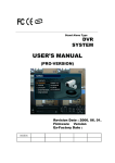
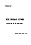
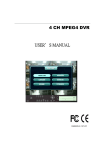
047200 - DVR BUILT IN LCD MONITOR
USER’S MANUAL VER V1.3
THE MOST STABLE AND RELIABLE REAL STAND-ALONE DIGITAL VIDEO RECORDER
• INDEX
• CHAPTER 1
1.
2.
3.
4.
(Specification & System Organization)
Specification ----------------------------------------------------------------------------------------------------Recording File Size ------------------------------------------------------------------------------------------Product Contents List ----------------------------------------------------------------------------------------System Configuration -----------------------------------------------------------------------------------------
• CHAPTER 2
(Panel Function)
1. Front Panel -----------------------------------------------------------------------------------------------------2. Rear Panel -----------------------------------------------------------------------------------------------------3. Remote Controller --------------------------------------------------------------------------------------------• CHAPTER 3
1.
2.
3.
4.
5.
6.
7.
3
4
5
6
7
8
9
(Installation)
8pin RJ 45 Modular Jack ----------------------------------------------------------------------------------Video Out ------------------------------------------------------------------------------------------------------Camera Selection -------------------------------------------------------------------------------------------Network Connection ----------------------------------------------------------------------------------------Alarm/Relay/PTZ Connection ----------------------------------------------------------------------------Power Connection ------------------------------------------------------------------------------------------Finishing Installation ----------------------------------------------------------------------------------------
10
10
10
10
10
10
10
※ Hard Disk Format ----------------------------------------------------------------------------------------------- 11
• CHAPTER 4
1.
2.
3.
4.
5.
6.
(Display)
System Power ON ------------------------------------------------------------------------------------------Screen View Selection ------------------------------------------------------------------------------------Change Screen Mode -------------------------------------------------------------------------------------Control PTZ/Focus -----------------------------------------------------------------------------------------Speaker Volume Control --------------------------------------------------------------------------------System Power OFF -----------------------------------------------------------------------------------------
• CHAPTER 5
12
12
13
13
14
14
(SEARCH)\
⊙ Go to Search Mode ----------------------------------------------------------------------------------------- 15
1. Search by Date/Time --------------------------------------------------------------------------------------- 15
2. Search by Event ---------------------------------------------------------------------------------------------- 16
• CHAPTER 6
⊙
⊙
1.
2.
3.
4.
5.
6.
Go to Menu ---------------------------------------------------------------------------------------------------Initial Menu ---------------------------------------------------------------------------------------------------Display ---------------------------------------------------------------------------------------------------------Record ---------------------------------------------------------------------------------------------------------Camera --------------------------------------------------------------------------------------------------------Audio -----------------------------------------------------------------------------------------------------------Alarm -----------------------------------------------------------------------------------------------------------System ----------------------------------------------------------------------------------------------------------
• CHAPTER 7
1.
2.
3.
4.
(MENU)
(CLIENT)
Remote Program Installation ----------------------------------------------------------------------------Monitoring Mode --------------------------------------------------------------------------------------------Search Mode ------------------------------------------------------------------------------------------------Setup -----------------------------------------------------------------------------------------------------------
• CHAPTER 8
18
18
19
19
24
25
26
27
32
35
38
45
(DDNS Connection)
1. DDNS Connection ------------------------------------------------------------------------------------------- 47
• OPTIONAL
1. Optional Cable ----------------------------------------------------------------------------------------------- 48
• Specification & Configuration
1. Specification
LCD
Hardware
Type
15.0” TFT LCD Panel
Pixel Pitch
0.297mm(H) x 0.297mm(V)
Pixel Arrangement
1024(H) x 768(V), RGB Vertical Stripe
Resolution
More than 500 TV Lines
CPU
32 bit DSP
HDD
Unlimited HDD Space
OS
RTOS
Video Input
4CH NTSC / PAL
Display Speed
120fps (NTSC) / 100fps(PAL)
Screen Modes
Recording Speed
1/4 Channel Mode
352x240 / 352x288
120 / 100 fps
704x240 / 740x288
60 / 50 fps
704x480 / 740x576
30 / 25 fps
NTSC : 352 x 240, 704 x 240, 704 x 480
Recording Resolution
PAL : 352 x 288, 704 x 288, 704 x 576
MPEG4 (Optimized)
Compressing Method
3~5 Kbyte @ 352 x 240 (PAL : 352 x 288)
Byte Size per Image
5~10 Kbyte @ 720 x 240 (PAL : 704 x 288)
6~16 Kbyte @ 720 x 480 (PAL : 704 x 576)
Recording Modes
Continuous, Motion Detection, and Sensor Activated, Time Recording
Recording Schedule
Setting Recording Schedule per Camera
Motion Detection
Supports the setting of Motion Sensitivity per Camera
Sensor / Camera / Alarm I/O
M : N Mapping
Camera Connector
Composite
BNC x 4
S-Video
Mini Din x 4
VGA Input
1 Input
Audio Input
1 Input
Sensor / Alarm
4 Input / 1 Output
P/T/Z Control & Port
RS-485
LAN
10 / 100 Base – TX Ethernet
Transmission Speed and No. of Connection
Depends on connection Status, Almost Real Time Monitoring
1 Connection (1 or 4CH Video)
Remote Transmission
Remote Live Viewing, Remote Playback and Remote File Copy
Remote Control
Remote Pan / Tilt / Zoom / Focus / Iris
System Recovery After Power Failure
Auto-Rebooting, Auto-Scan and Recovery of Data
System Operation
IR Remote Controller
Storage Temperature and Humidity
20~65℃ / 20~95% RH
Operating Temperature and Humidity
5~50℃ / 20~80% RH
Power
DC 12V, 5A (Adaptor Included)
Dimension
350(W) X 315(H) x 55(D)mm
Weight
6.3 Kg
Remote S/W
Remote Viewer (4CH)
3
• Specification & Configuration
2. Recording File Size
NTSC
Quality
HDD
Highest
High
Standard
Low
PAL
720x480/7fps
720x240/15fps
352x240/30fps
704x576/6fps
704x288/12fps
352x288/25fps
Hour
Day
Hour
Day
Hour
Day
Hour
Day
Hour
Day
Hour
Day
80G
40
1.7
37
1.5
41
1.7
42
1.8
40
1.7
48
2.0
120G
60
2.5
57
2.4
62
2.6
67
2.8
62
2.6
72
3.0
160G
79
3.3
74
3.1
82
3.4
89
3.7
84
3.5
96
4.0
200G
98
4.1
94
3.9
103
4.3
110
4.6
105
4.4
120
5.0
250G
125
5.2
115
4.8
130
5.4
137
5.7
132
5.5
151
6.3
80G
53
2.2
46
1.9
58
2.4
56
2.3
54
2.3
65
2.7
120G
78
3.3
69
2.9
86
3.6
86
3.6
84
3.5
98
4.1
160G
106
4.4
94
3.9
115
4.8
115
4.8
113
4.7
130
5.4
200G
132
5.5
115
4.8
144
6.0
144
6.0
141
5.9
159
6.6
250G
166
6.9
144
6.0
180
7.5
180
7.5
178
7.4
204
8.5
80G
79
3.3
74
3.1
93
3.9
81
3.4
79
3.3
101
4.2
120G
120
5.0
100
4.2
139
5.8
127
5.3
125
5.2
151
6.3
160G
158
6.6
149
6.2
185
7.7
168
7.0
165
6.9
201
8.4
200G
199
8.3
185
7.7
230
9.6
211
8.8
206
8.6
252
10.5
250G
247
10.3
230
9.6
290
12.1
264
11.0
259
10.8
317
13.2
80G
122
5.1
123
5.1
154
6.4
127
5.3
139
5.8
171
7.1
120G
182
7.6
184
7.7
230
9.6
199
8.3
216
9.0
257
10.7
160G
245
10.2
247
10.3
310
12.9
264
11.0
290
12.1
343
14.3
200G
305
12.7
310
12.9
384
16.0
331
13.8
362
15.1
427
17.8
250G
382
15.9
386
16.1
480
20.0
412
17.2
451
18.8
535
22.3
Average Frame Size (Kbyte)
Average Bit Rate (Kbyte/sec)
FPS / Resolution
N
T
S
C
P
A
L
Highest
High
Standard
Low
Highest
High
Standard
Low
CIF/30FPS (352x240 )
4.5
3.2
2
1.2
135
96
60
36
2CIF/15FPS (720x240 )
10
8
5
3
150
120
75
45
D1/7FPS (720x480)
20
15
10
6.5
140
105
70
45.5
CIF/25FPS (352x288 )
4.6
3.4
2.2
1.3
115
85
55
32.5
2CIF/12FPS (704x288 )
11
8.2
5.6
3.2
137.5
102.5
70
40
D1/7FPS (704x576)
21
16
11
7
131.25
100
68.75
43.75
NTSC
PAL
Resolution
Max FPS
Resolution
Max FPS
352x240
120
352x288
100
720x240
60
704x288
50
720x480
30
704x576
25
4
• Specification & Configuration
3. Product Contents List
Please Confirm the Contents When You Open the Package.
① Basic Contents
DVR Monitor
User’s Manual
RJ-45 Modular Jack
Cable X 4 (BNC/RCA)
Remote Controller
DC 12V Adaptor
Remote Client Program
Installation CD
80G HDD default
5
Power Cable
AAA Battery X 2
• Specification & Configuration
4. Configuration
6
• Panel Function
1. Front Panel
①
②
③ ④
⑧
⑩
1
⑤
⑥
⑦
2
3
⑨
4
⑪
① POWER : System Power On/Off
② MENU : Used when changing the menu of SYSTEM SETUP.
③ ENTER : It is used as the SELECT key.
④ RETURN : Cancel setup or return previous mode.
⑤ SEARCH : Go to search mode for searching recorded video.
⑥ SCRMEDE : Select screen division mode or rotation mode.
⑦ PTZ/FOCUS : Go to camera PTZ/Focus control
⑧ LED Indicator : Indicate present system situation
(POWER : SYSTEM On/Off , RECORD : Record On/Off,
NETWORK : Client Network connect , ALARM : Alarm sensor)
⑨ Search controller : Searching recorded video or control menu & PTZ/Focus
▲,▼, button are for volume control function .
⑩ Channel select button : Select channel or input password
⑪ Remote controller sensor input
Tip
• The Soft Button of power is styled to prevent failure by wrong operation.
• When Remote Controller Sensor Input is blocked by something, it may cause
remote controller do not work properly.
• Initial Password for all “Administrator, User, Network” is 1234.
7
• Panel Function
2. Rear Panel
①
②
③ ④
⑤
⑥
① 8 pin RJ 45 Modular Jack : Video In + Audio In + RS-485 + Camera Power ( Max.)
② Video Out : BNC Out
③ Camera select switch : NTSC / PAL
④ Ethernet (TCP/IP) : Connect Port for LAN Cable
(It is possible for user to connect the DVR by Remote Client program.)
⑤ Alarm/Relay/RS-485 : Connect Port for Sensor & Relay, PTZ
⑥ Power : DC 12V, 5A (For observation kit with camera (DIN Cable) : 8A adaptor is needed)
Tip
• After installation, please connect the power.
• Please use static power adaptor to operate it.
8
• Description
3. Remote Controller
MENU: Open Menu
POWER:
System
On/Off
Channel Select Button
(4ch Available, #1~4 Button)
RETURN:
ENTER: Apply Setup Change
Cancel Setup
or Return to
Previous Menu
Search Controller: Control Playback Option
(EX. Speed of Playback, Move on Menu, Control
PTZ/Focus, Volume)
Change Screen Open Search
Mode
Mode
PTZ/IRIS Mode
• Unused Button's Description is Omitted.
• Remote Controller can Operate when Remote Controller Sensor Input Part Reacted.
• If there are many DVRs at the same place, they are reacted together when press remote controller.
9
• Installation
1. 8pin RJ 45 Modular Jack
Camera in (BNC/RCA/DIN)+ Audio in (RCA/DIN) + Power + RS-485
•Default : Camera (BNC) + Audio (RCA)
•Optional Cable Selection (refer to page. 48 )
2. Video Out
Connect DC Power Input Terminal and Static Adaptor
3. Camera Selection
Switch to change video mode NTSC/PAL
4. Network Connection
Connect Ethernet Terminal and Network Cable
①
5. Alarm/Relay/PTZ Connection
②
③④ ⑤
⑥
Connect Port for Sensor & Relay, PTZ
IN1
IN2
IN3
IN4 GND NO COM
ALARM
RELAY
NC
D+
D-
RS-485
① ALARM
Alarm Input - ‘IN1, IN2, IN3, IN4’ : Connect Sensor Input by Channel
‘GND’ : Connect Ground System
② RELAY
Alarm Output – ‘NO, NC’ : After Checking Alarm Output Type (Normal Open or Normal Close) and Connect to ‘NO, NC’
‘COM’ : Connect Remain Grounding Conductor
③ RS-485
Connect PTZ Camera – ‘D+, D-’ : Connect PTZ Camera Control Line (+ , – Terminal)
PTZ 14 Pin Cable
RS485
⑨ R+
⑩ R⑪ T+
⑫ T-
D+
D-
6. Power Connection
DC 12V, 5A (For observation kit with camera (DIN Cable) : 8A adaptor is needed)
10
• Installation
※ Hard Disk Format
- If you install the unformat Hard Disk, System can’t recognize the Hard Disk.
Please install the format Hard Disk.
11
• Display
1. System Power ON
• Press Power Button once to turn on system
• After Checking Hard Disk, Input password to operate.
• Initial Screen View Mode is Quad Division Mode
and Recording Mode
CAMERA
2004/01/01
00:00:00
Initial Display situation after system
installation
• Each Channel Indicate, Camera Name & Recording Status
• Present Time & Date Indicate at Monitor Central Lower Side
Tip
• Check System Condition at LED
POWER : Showing System On/Off
RECORD : Showing Record On/Off
NETWORK : Showing Client Connection Status
ALARM : Lighting when Sensor Alarm Activate
2. Select Screen Mode
• Select One Channel among 4 Channels
• Move to One Enlargement Watch Mode when Quad Screen Division Mode
• Move to One Enlargement Watch Mode when Rotation Mode
12
• Display
3. Convert Screen Mode (SCR MODE)
• User can Select 3 Kinds Watch Mode
① Quad (4CH) Division Watch Mode
② Selected 1CH Watch Mode
③ 4CH Rotation Watch Mode
• Quad (4CH) Watch Mode is Initial Mode when System Start
Quad (4CH) Division
Watch Mode
Selected 1CH
Watch Mode
4CH Rotation Mode
4. PTZ/FOCUS Control
• Control Camera PTZ (Pan/Tilt/Zoom) & Focus (Only Usable for Proper Camera)
PTZ/FOCUS
• Press PTZ/FOCUS Button to Open PTZ Menu at Right-Under Side and Control by
Search Controller
• Press PTZ/FOCUS Button Second Time to Open FOCUS/IRIS Menu and Control by
Search Controller
PTZ CTL
UP
LEFT RIGHT
DOWN
Control Camera PTZ &
Focus by Search Controller
on PTZ Menu
FOCUS/IRISCTL
UP
LEFT RIGHT
DOWN
Search Controller
13
• Display
5. Speaker Volume Control
• Easy to control speaker output volume monitoring
“Live & Recorded image”
5. System Power OFF
• Press Power Button to turn on monitor.
• Press Power Button More than 3 seconds to see “shutdown popup window.”
Tip
• System Log-On Available ID : ‘Administrator’, ‘Manager’, ‘Operator’, ‘Network’
Administrator: All Function Access (System On, Shutdown, Setup, Search)
Manager: System On and Search
Operator: System On
Network: Connect by Remote Program
14
• SEARCH
⊙ Go to Search Mode
SEARCH
• Press Search Button and Log-In
Administrator or Manager
• Use Direction Key to Move Menu
• To Open Each Menu Press Enter
ENTER
Search Recorded Data
RETURN
• Return to Previous.
(Move to Previous Menu or Exit Search
1 Mode and Return to Watch Mode)
1. Search by Date/Time
- Possible to Search Recorded Date & Time
① Move Cursor to Selected Date in Calendar
(Recorded Date & Time Indicated by Gray Color)
② Press Enter to Open Selected Date
③ Recorded Time Appear to Under Side
④ Press Enter at Selected Time
(One Scale is 15 Minutes)
⑤ Menu Disappear and Output Recorded Video
• Showing Recorded Date & Time at Left-Upper Side
as Watch Mode.
Showing Playing Condition at Right-Under Side.
• Channel Selection Button in Watch Mode & SCR Mode
Button are Apply the Same as Search Mode.
(But Menu, Search, and PTZ/Focus Buttons are Exception)
15
2004/01/01
00:00:00
>
• SEARCH
• Control Playing Video
①
: Normal Playing Mode (Normal Speed (1X) Forward Playing)
②
: Normal Speed Backward Playing
③
: Pause Video
④
: Fast Forward (2 ~ 64 Speed)
⑤
: Fast Backward (2 ~ 64 Speed)
⑥
: Audio Volume Control
※ Press Normal Forward/Backward Button in Pause, Move to Next/Previous Frame.
2. Search by Event
- Searching Video with Event Occurrence to Set up Period
Set up Period to Select Start Date & Finish Date for
Searching Event
Alarm : Searching Alarm Event during the Selected
Period
Motion : Searching Motion Detected Event during
the Selected period .
Timer : Searching Schedule Change or Recording
Setup Change Event
System : Searching Power On/Off Event (etc.)
Concerned System Event
Event List Showing at Below Output Window
Tip
• Alarm, Motion, System can be Selected plural by Check (V)-(ENTER)
• To Change Setup, Press Enter and Press Direction Key
After Changing Setup, Press Enter to Exit.
16
• SEARCH
• Date : Indicate Event Occurrence Order & Date
Time : Indicate Event Occurrence Time
Event : Indicate Event Contents & Camera No.
• Event Searching Method
① User can Search Event Using Direction key
② Search Event to Press Enter at Selected Event
from Event Occurrence Time
③ Control Video is the same way as Time Mode Control
Tip
• The Search by Event is not Based on Video, but Event Occurrence Time.
17
• MENU
⊙ Go to Menu
① Press Menu Button on Front Panel in Watch Mode
② Ask Password
③ Input Password Using by Channel Select Button
[1][2][3][4])
④ After Input Password Press Enter to See Menu
Tip
• Initial Password for all “Administrator, User, Network” is 1234.
• Showing Password as *
• Changing Password (MENU->6.System->4.Password )
• Only Watch Mode can go to Menu.
(Search & PTZ/Focus Mode can’t move to Menu)
⊙ Menu Initial
• Every System Setup can be changed or maintained
•
Move to Menu Using by Up &
Down and Left, Right Button
•
To Open Detail Menu or to Apply Input
•
Return to Previous Menu or Return to Watch Mode
18
• MENU
1.Display
- Video Setup for Watch Mode
1.
Date/Time : Date & Time Mark On/Off
2.
Title : Camera Name On/Off
3.
Status : Record Condition Mark On/Off
(Recording: Red, Pre-recording : Green)
4.
Border : Border Mark On/Off
when 4CH Division Watch Mode
5.
Border Color : Select Border Color
(White, Blue, Red, Yellow, Green, Gray)
6.
Sequence Dwell : Setup Rotation Cycle Time
(1~60 Sec.) when 4CH Rotation Mode at Watch
Mode
7.
Spot-Out Dwell : Setup Spot-Out Time Cycle
(1~60 Sec.) to Transmit Video
8.
Deinterlace Mode : Remove Screen Spread on High
Resolution , Low Frame
※Only Applying When D1(704X480)
2.Record
- Setup Image Recording
2.1 Size/Rec.Rate/Quality – Setup Recording Resolution, Compression Rate and Quality
-Camera : Indicate Camera No. to Setup
-Size : Setup Resolution
-Rec.Rate : Setup Compression Rate
-Quality : Setup Quality of Recording Video
19
• MENU
• Size : 352*240, 720*240, 720*480
Rec.Rate : Possible to Select (1~30)
Quality : Possible to Select 3 levels
(Highest, High, Low, Standard)
• Indicate Frame No. to Control Size & Rec. Rate
Overlimit Recording Capacity
Tip
• If Frame Over, Showing a Message ‘Overlimit Recording
Capacity’ and Impossible to Change Size & Rec. Rate
• When Setup Refer to Below NTSC, PAL Type
NTSC : 352*240(30fps), 720*240(15fps), 720*480(7fps)
PAL : 352*288(25fps), 704*288(12fps), 704*576(6fps)
• Possible to Setup Size & Rec. Rate, Quality per Each Channel
• When Apply Change Setup, Press Enter, When Cancel Change Setup, Press Return.
2.2 Timer Recording Setup – Record On/Off or Time, Motion Setup
• Camera : Indicate Camera No. to Setup
• Record : Record On/Off
• Start : Setup Recording Start Time (0~24 hr)
• Stop : Setup Recording Finish Time (0~24 hr)
* Recording Time is between Start Time and Finish Time.
• Motion : Motion Detection Recording On/Off
(Record Setup must be ‘On’, for Motion Detection Recording)
20
• MENU
2.3 Motion Detection Setup – Motion Detection Area & Sensitivity
• Camera : Indicate Camera No. to Setup
• Sensitivity : Control Sensitivity (1~100)
Large No. is More Sensitive.
• Region : Setup Motion Detect Range
Entirely – Select Entire Screen
Partially – Select Partial Screen
• When Choose Region as Partially, Move to Partial
Range Setup. Press Enter After Partial Range Setup
to Finish Region Setup.
• Pre-Motion Duration : Setup Pre-Motion Duration Time.
(1~5 sec)
• Post-Motion Duration : Setup Motion Detect Recording
Time after Motion Detected (5sec~3min)
2.4 Alarm Recording Setup – Recording Setup for Alarm Activated
• Camera : Indicate Camera No. to Setup
• Record : Setup Record On/Off when Alarm Activated
• Start : Setup Alarm Recording Start Time (0~24 hr)
• Stop : Setup Alarm Recording Finish Time (0~24 hr)
• Pre-Alarm Duration : When Alarm Recording, Setup
Start Recording Time before Alarm Activate (1~5sec)
• Post-Alarm Duration : Setup Alarm Recording Time
after Alarm Activate (5sec~3min)
Tip
• Motion Setup Work by Time Schedule and Alarm Schedule Work Independently.
21
• MENU
⊙ Time Recording Weekly Setup
①
②
Weekly mode Setup at Record Setup
Scheduled Region Indicated Yellow
③
④
After ‘Deselect’ Schedule, Activated Region by
Press ‘ENTER’ and Select Date & Time to Move
Cursor
After Selecting Region and Press ‘ENTER’ Again to
Finish Schedule Setup (Red)
⑤
⑥
• Select All : Entire Region Select
• Deselect All : Cancel Region
• Save&Exit : Save Changing Setup & Exit
• Cancel : Cancel Changing Setup & Exit
Setup Date & Time Schedule in the Same Way.
After Finishing Schedule Setup,
Press ‘Return’ for Save & Exit
22
• MENU
⊙ Partial Motion Region Setup
:Non-Activate Move Cursor
①
:Activate Partial Setup Cursor
:Partial Setup Finish Cursor
②
Region Initial View
④
When Select Multi Region,
Using Direction Key in ② to
Expand Non-Activate Region
⑦
:Non-Activated Region
③
Move Cursor by Direction Key and
Press Enter at Selected Region
⑤
Press Enter again to see Region
as a Blue Color and Setup NonActivate Region
⑥
Press Enter to Select Multi
Non-Activate Region
Same Method as ④⑤, Possible to
Expand Non-Activated Region
⑧
• Select All : Select Entire Region
• Deselect All : Cancel Region Setup
• Save&Exit : Save the Change Setup & Exit
• Cancel : Cancel Change Setup & Exit
For Reducing Partial Region,
Cancel Non-Activate Region in
Same Way as ④⑤
When Finishing Partial Region
Setup, Press Enter to Save &
Exit
23
• MENU
3.Camera
- Setup Camera
3.1 Status/Title Setup – Camera Connection Status & Camera Name Setup
• Camera : Indicate Camera No. to Setup
• Status : Indicate Camera Status
(Connected/Disconnected)
• Title : Setup Camera Name to Show Left-Upper Side
Tip
• Title Input Method
Using Direction Key, Up & Down Keys for Alphabet A~Z, Numerical No. 0~9
Left-Right Keys for Move to another Letter.
3.2 Covert/PTZ Setup
• Camera : Indicate Camera No. to Setup
• Covert : Setup Covert On/Off
*What’s Covert?
When Covert On Watch Mode, Display Video is
Hidden, but Recording is On.
• PTZ Address : Select PTZ Camera Address
• PTZ Protocol : Select Kind of PTZ Camera
• Baud Rate : Setup PTZ Communication Speed
(2400, 4800, 9600 BPS)
※PTZ Supplied Protocol :
Samsung(MRX-1000,SCC-641), HoneyWell(SD1, GMC)
Kalatel(KTD-312), Panasonic(604, 850),
PELCO-D, PELCO-P, Sensormatic, Vicon, Sunin DSC-230,
LILIN FASTDOME, FASTRAX II, GC-655N, D-MAX,
SCAN DOME II
24
• MENU
3.3 Color Setup – Control Video Color
• Camera : Indicate Camera No. to Setup
• Brightness : Control Monitor Bright
• Contrast : Control Monitor Contrast
• Color : Control Monitor Color
• Tint : Control Monitor Tint
* All Setup Possible to Control 0~100
4.Audio
- Setup Audio
4.1 Audio Recording Setup – Audio In Setup
• Camera : Indicate Camera No. for Setup
• Audio Rec. : Setup Recording On/Off from External Audio In Terminal
• Audio Ch. : Setup Audio In Terminal Channel & Audio Output Camera
Tip
• User can Listen Saved Audio with Saved Video
• Audio Check in Search is Possible Only Normal Speed (1X) Forward
Playing at 1CH Mode (Audio Recorded Channel)
25
• MENU
4.2 Live Audio Setup – Audio Out Setup
• Live Audio : Audio Output ON/OFF
Live Audio Output from Audio In Terminal
• Monitoring Ch. : Select Channel for Audio Output
Nr. 1~4 Audio In
5.Alarm
- Setup Alarm & Relay
5.1 Alarm Input Setup – Alarm Sensor Setup
• Alarm : Indicate Alarm Input Terminal No.
• Status : Setup Alarm Sensor Connection Status
(Connected/Disconnected)
• Camera : Input Camera No.1~4 to Connect Alarm
• Type : Setup Alarm Sensor N/Open, N/Close Type
Tip
• Generally Alarm Sensor can be Divided Two Types.
Normal Open Type is Open Sensor Electrically and Reacted when
Signal is Connected.
Normal Close Type is Close Sensor Electrically and Reacted when
Signal is Disconnected.
26
• MENU
5.2 Relay Output Setup – Alarm Relay Setup
• Alarm : Indicate Alarm Input Terminal No.
• Relay Out : Setup Relay Connect with Alarm Sensor
• Mode : Setup Reacted Relay as Latched/Transparent Mode
• Duration : Setup Reacted Relay Time
(5sec~5min or Until key-in)
• Relay Type : Setup Relay Type N/Open or N/Close
Tip
• Latched/Transparent
Latched – When Sensor Alarm Activated, Relay Reacted in Setup Duration
Transparent – Relay Reacted Temporary During Sensor Alarm Activate
6.System
- Basic Environment Setup
6.1 Date/Time – Date & Time Setup
• Date : Setup Present Date (YYYY-MM-DD).
(If Time Setup to Past Date, Ask Delete Data for the Past Date.
NO->Date/Time No Change, YES->After Delete Past Data and Change Date/Time )
• Date Format : Select Date Output Type (Ex: 2004-00-00, 2004/00/00)
• Time : Setup Present Time
• Time Format : Setup Time Type as 12 Hour Base or 24 Hour Base
• Daylight Saving : Summer Time Applying Status
27
• MENU
6.2 Network – Setup TCP/IP
• IP Address : Input IP Address
• Gateway : Input Gateway IP for Internet Server
• Subnet Mask : Input Subnet Mask IP
• Network Speed : Setup Network Speed
(Network Speed from System, Depend on Network Status)
※ When you the changed setting would be applied after rebooting
You should reboot to apply changed setup change
6.3 Buzzer Setup – Setup Key Sound to Speaker
• Alarm Input : Alarm On/Off when Alarm Activate
• Videoloss : Alarm On/Off when Camera Disconnected
• Disk Full : Alarm On/Off when Hard Disk Full
• Disk Error : Alarm On when Hard Disk Error
• Key Input : Setup Key Input Sound
6.4 Password – Setup Password
6.4.1 Administrator Password – Setup Menu & System On/Off
• Current Password : Input Current Password (Initial Password : 1234)
• New Password : Input New Password
• Re-enter the Password : Re-Confirm New Password
• Save & Exit : Applying New Password
28
• MENU
6.4.2 Manager Password – Available to monitor & search but cannot change setup
• Current Password : Input Current Password
(Initial Password : 1234)
• New Password : Input New Password
• Re-enter the Password : Re-Confirm New Password
• Save&Exit : Applying New Password
6.4.3 Operator Password – available to monitor only cannot control setup other search
• Current Password : Input Current Password
(Initial Password : 1234)
• New Password : Input New Password
• Re-enter the Password : Re-Confirm New Password
• Save&Exit : Applying New Password
6.4.4 Network Password – Setup Remote Connection Program Password
• Current Password : Input Current Password
(Initial Password : 1234)
• New Password : Input New Password
• Re-enter the Password : Re-Confirm New Password
• Save & Exit : Applying New Password
29
• MENU
6.5 Disk Write Mode – Setup Hard Disk
• Disk Overwrite : Select Overwrite Permission when Hard
Disk Full
O N: Overwrite Hard Disk from Oldest Data
OFF: When Hard Disk Full, Stop Recording and
Buzzer Activate (Refer to Menu 6.3 Buzzer Setup)
• Disk Initialize Now : Refreshment Hard Disk
All Recorded Data Deleted
• When Select Disk Initialize, Alarm Message Showing.
Select ‘Yes’ to Start Disk Initialize.
※When Change Disk Overwrite ON/OFF Mode, the Change will be Applied from Changing Time.
For Example When Overwrite On Mode & HDD Full, Change to Overwrite Off Mode and then it will be Applied New Data
Fill HDD Full after Changing Time.
6.6 System Information – Product information (Version etc)
• S/W Version : Indicate S/W Version of the Product
• H/W Version : Indicate H/W Version of the Product
• Video Signal Type : Indicate Video Signal Type
• Disk Size : Indicate Hard Disk Capacity
• Number of HDD : Indicate Present Installed HDD No.
• IP Address
• MAC Address
6.7 Factory Default – Every Setup Initializing
• Press Enter to Start Initialize
• Showing Warning Message and Press OK to Run Initialize
• If do Factory Default, Every Setup is Initialized, but
Saving Image is Not Deleted.
30
• MENU
7. USB BACK UP
• USB device auto detection
• Back up date & time
• Selectable subject : Video/ Audio/ Event
• You can back up data by USB device auto detection.
• Set data and time which you want to back up and
then press back up button
• Back up will be started
• You can select “Channel”, “Audio” & “event” which
you want to back up.
* Data format : AVI file
31
• CLIENT
• System Requirement
① Main Board (CPU): Celeron 500-700(Minimum), Pentium 4 recommend
② OS: More than Windows 98,DirectX 7.0A
③ Memory (RAM): More than 128 M
④ VGA: Overlay YV12 Format Graphic Card
All Radeon, Nvidia (Above Geforce) Matrox (Above G400) Compatible Video Card
※ Above DIVX Codec 5.1 (When Use Media Player)
• DVR Remote Agent 1.0 Install
① Open CD-ROM Drive and Run DvrRemoteAgentSetup.exe and then Appear Setup Menu
② Close All Running Software and Press Next to Move Next Step
32
• CLIENT
③ Ask designate Folder to Install DvrRemoteAgent 1.0,
Recommend Basic setup c:\program files:\DvrRemote Agent 1.0
Click Next
④ Showing Progress of Copy of Files
⑤ Appear DirectX 7.0a Install Menu. If DirectX Version Lower than 7.0a, Press Yes to Start Install
33
• CLIENT
⑥ When Finishing Installation, System must be Restarted. Click ‘Yes’
⑦ Finish DvrRemoteAgent 1.0 Program Installation
34
• CLIENT
1. Monitoring Mode
③
1.1 Function Introduction
①
④
⑤
⑥
⑦
⑧
⑨
⑩
⑪
②
⑫
① Main Screen Image : Shows Present Surveillance Camera Image
② Camera Selection Button : Indicates Connected Camera No. & Select Image to Click Camera No.
③ Hidden/Exit : Hide DVR Client Window or Exit Program
④ Time Output : Showing Present Time & Date
⑤ SEARCH : Move to Search Mode to Play Video
SETUP : Move to Setup to Change Network Setup or Option
⑥ Connect : Connect Server (DVR)
Disconnect : Disconnect from Server
⑦ PTZ Control Button : Control Camera PTZ & Focus
⑧ Save by AVI file : Transmission Live Image Save by AVI File
⑨ Color Adjustment : Adjust Color of Live Transmission Image
⑩ Exit : Exit DVR Client
⑪ Screen Division Selection : Change Screen Division Mode
⑫ I/D Selection : Select I/D to Connect Server
35
• CLIENT
1.2 Screen Division Selection
• 1*1 View : Showing One (1) Video which User Selected
(Selection Video by Camera Selection Button)
• 4*4 View : Quad Screen Division Mode
• Scenario View : One Large Screen Mode Showing One by One (1*1 View)
Depend on User Selection Time (Not Work Screen Division Mode)
• Full Screen View : Present Video Move to Full Screen Mode
Mouse Double Click to Return Previous move
*Mouse Double Click Make the Same Function as Full Screen.
1.3 P/T/Z Control
• FOCUS/ZOOM Select Button : Focus or Zoom Control by +,- Button
• P/T/Z Controller : Camera P/T/Z Control by Direction Keys
• +,- Control Button : Focus or Zoom Control
1.4 Selection Network I/D
Network Information Icon
• Select I/D to Connect Server.
• I/D can be Add, Change and Delete at Setup
• Click Network Information Icon, to See a
Popup Window for Connected Server I/D, IP,
and Port Information.
36
• CLIENT
1.5 AVI File Conversion
• Click AVI Conversion Button to Start AVI File Conversion
• During AVI Conversion Showing a Message and before
Click ‘Stop”, Save AVI File continuously
• Press ‘Stop’ to Open Designated File Name & Saving
Location, and Save AVI File
• Saved AVI File can Open Ordinary Moving Picture Player
• Moving Picture Player Codec Version is Above Divx 5.1.
1.6 Color Adjustment
• Click Controller button to Control Color
• Change Brightness, Contrast, Saturation from 0 to 100
• Click OK to Finish Changing Setup
37
• CLIENT
2.Search Mode
2.1 Function Introduction
①
③
④
⑤
⑥
②
⑦
⑧
① Search Screen : Playing Selected Video
② Search Bar : Search & Indicate Camera Recording Situation by Time Bar
③ LIVE : Return to Live Mode
SETUP : Mode to Change Network Setup or Option
④ SEARCH Option : Backup Video or Search Event
⑤ Camera Selection Button : Select Camera at the 1*1 View
⑥ Search Controller : Control Playing Video
⑦ Screen Division Selection : Change Playing Screen Division Mode
⑧ Quick Search : Find Image to Designate Date & Time
38
• CLIENT
2.2 Search Method
⑤
①
②
⑥
④
③
① Indicate 0~24 Hour
② Indicate Recording Situation (Gray : No Record, Green : Recorded Image at the Time)
③ Search Bar : Select Video by Dragging Mouse Search Controller in Recorded Area
④ Indicate Camera Channel to Confirm Camera Recording Situation
⑤ Refreshment Recording Information Situation Window by Camera Channel
⑥ If Connected Channel is more than 5ch, Another Channel will be Scrolled.
Play Video as Normal
Speed (1X)
Stop Play Video
Program Exit
AM
Search Bar will Move, if
Input Date & Time
Click Date Setup and
Select Date on Calendar
39
• CLIENT
2.3 SEARCH Option
⑤Log Search
⑥Event Viewer
①Backup
②Backup Play
④Print Image
③Save Image
① Backup – Backup Image from Server to Remote PC
• Backup Time : Designate Backup Time (Now or Later)
• Designate Backup Date & Time when you chooseLater
AM
• Source :
AM
AM
AM
PM
AM
AM
PM
Designate Backup Image Data Length to
Input Start Time & End Time.
• Channel : Check Camera Channel for Backup
• Select All
Deselect All
•Press OK to Open Backup Status & Start Backup.
•When Finish Backup, Back Status Window Disappear & Backup Data would Saved at Hard Disk
Root Folder in Remote PC.
40
• CLIENT
② Backup Play (DVR Player) – Transfer to DVR Player
①
②
③
④
⑤
① Showing Image (Possible to Only 1*1View Mode)
② Backup File Open to Play First Video
Ex. : ch04_10261450_10261455.rec ( Backup File for # 4 ch. October.26, 14:50 ~14:55 )
③ Indicate Total Recorded time of Present Playing Picture.
④ Indicate Present Time & Date and Possible to Search Time & Date
⑤ Search Controller, the Same Way of Previous Search
Tip
• Backup Play Setup in Search Mode is the Same as DVR Player,
so it can be Run Independently without Running Remote Program.
41
• CLIENT
③ Save Image – Capture Image & Saving Image at Hard Disk or Removable Disk
• Click ‘Save Image’ Icon During Playing Video
• Designate File name, File Type (JPG,BMP), and Location and Press Saving
• Conversion and Saving Image from Remote Viewer
③ Print Image – Present Image Capture and Print Out Image
• During Play Video, Click ‘Print Image’
• After Selecting Printer, Start Image Printing
• Print Out Remote Viewer Image
42
• CLIENT
③ Log Search – Find Video Centering around Event Log at Server
①
② ③
④
⑤
⑥
⑧
⑦
① Input Start Time and End Time at the Selected Date to Search Event
When Press Search Button, Event Output at the Below Window
② Indicate Event Log Order No. ( Max Event Log No. of 1 Page is 100 )
③ Indicate Event Occurred Camera No.
④ Indicate Event Occurred Time & Date
⑤ Indicate Event Detail Description
⑥ Move to Previous Page
⑦ Move to Next Page
⑧ Move to User Select Page
⑨ After Select Event, Move Search Bar in Search Mode
⑩ Return to Search Main to Play Event Image
43
⑨
⑩
• CLIENT
④ Event Viewer – Showing Present Event in Server & Find Image
① Indicate Event Occurred Order No.
② Indicate Event Occurred Camera No.
③ Indicate Event Occurred Time & Date
④ Indicate Event Detail Description
⑤ After Select Event, Move Search Bar
in Search Mode
⑥ Return to Search Main to Play
Selected Event Image
① ②
③
④
⑤
⑥
44
• CLIENT
3.Setting
①
①
②
②
⑦
③
⑧
④
⑨
⑤
⑩
⑥
3.1 Connection ID Setup
① ID Status : Indicate Present Saving ID & ID Information
② Input Name to Add or Amend ID
③ Input IP Address to Add or Amend Server
④ Indicate Port No.
⑤ Input ID for Connecting Server
⑥ Input Password for Connecting Server
⑦ Click to Input New ID Information
⑧ After Input All ID Information, Add ID Information at ID Status
⑨ After Amend All ID Information, Applying Change ID Information
⑩ Selected ID Delete at ID Status
Tip
• Initial ID & Password is ‘NETWORK’ & ‘1234’
45
③
④
• CLIENT
3.2 Option Setting
① Control Screen Rotation Time in Scenario Mode at Watch Mode
(Possible to Setup from 1~300 sec.)
② Possible to Select Event Kind Plurally from Server. Remote Client Only can See Selected Event.
(System, HDD, Alarm, Video, REC)
③ Setup Print-Out Image of Information Display from Server (Name, Date, Resolution)
④ Designate Backup Image Saving Folder at Remote PC
46
• DDNS Connection
1. Setting Domain Name Connection
When you have finished DDNS network setup and reboot,
1. Check the MAC address in “System Information” menu.
2. The domain name is "MAC address.dvrlink.net”.
EX) If Mac Address is 00-11-5f-01-0a-7a, the domain name is "00115f010a7a.dvrlink.net"
3. You can connect by "00115f010a7a.dvrlink.net" on the remote agent program or Web browser.
1.1 Remote Agent Program
①
②
③
④
⑤
⑥
⑦
⑧
⑨
⑩
① Server List : List of site server information
② Input Site Name
③ Input Server Domain name
④ Indicate Port No. Port information should be matched with server setting
⑤ Input ID for Connecting Server.
⑥ Input Password for Connecting Server.
⑦ To create new site information.
⑧ Adding edited site information
⑨ Modifying existing site information
⑩ Remove selected site information
1.2 Web browser
Type domain name at URL address column.
47
• OPTIONAL
1. Optional Cable
MBA-100
MBP-101R
MRA-102
MRAP-103
MBAP-104
MRP-105R
MD-018(18M)
MD-030(30M)
MD-045(45M)
MD-018R(18M)
MD-030R(30M)
MD-045R(45M)
48