1
20
VENTING INSTALLATION
Installing Log Set (Cont.)
Decorative Facing
PILOT ASSEMBLY ADJUSTMENT
BURNER FLAME ADJUSTMENT
INSTALLATION
PILOT ASSEMBLY
ADJUSTMENT
Continued
9.
10.
11.
12.
13.
14.
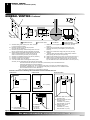
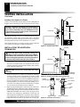
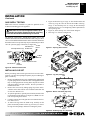
Place logs “B” as shown in Figure 45. Lift the end of log “A”
that will be propped up and place log “B” under it. At the same
time, the other side of log “B” is placed over the other log
“A”. Repeat procedure for the other log “B”.
Take twigs “C” (shaped like a “Y”) and place them as shown
in Figure 46.
Take twigs “D” (bent twig) and place them as shown in Figure 46.
Place twig “E” across the top of logs “B” a shown in Figure 46.
When finished installing the logs, close the glass doors while
making certain that the safety door switch is fully depressed by
the door frame before securing the four (4) spring loaded latches.
Replace the louvers in reverse order with the grilles pointing
in the down position.
WARNING: Improper installation, adjustment, alteration, service, or maintenance can cause injury or
property damage. Refer to this manual. For assistance or additional information, consult a qualified
installer, service agency, or gas supplier.
Left
Front
Back
A
B
B
A
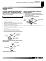
The pilot assembly is factory preset for the proper flame height.
Alteration to these settings may have occurred during shipping and
handling. If this is the case, some minor adjustment may be necessary and should be done by a qualified technician. To access the pilot
assembly, the glass door must be opened. The proper settings for the
thermopile height should be at a distance of 3/8" (.95cm) to 1/2"
(1.3cm) from the pilot flame as shown in Figure 47.
1/8"
(0.3cm)
3/8" - 1/2"
(.95cm-1.3cm)
Figure 47 - Correct Pilot Flame Pattern
BURNER FLAME ADJUSTMENT
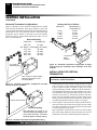
The air shutter, located at the underside of the main burner (see
Figure 48), has been factory preset to the proper air-to-gas ratio
which results in an even, clean burning flame across the burner (see
Figure 49). If readjustment is necessary, you can restore the proper
air-to-gas ratio by loosening the air shutter screw and rotating the air
shutter until the proper flame setting is achieved (the shutter's
normal setting is “full opened”. Do not forget to retighten the air
shutter screws.
Air Shutter
Right
Burner
Orifice
Figure 45 - Installing Logs “B ” (Top View)
Left
C
E
C
Venturi Tube
Front
Back
D
Firebox Bottom
Burner Gas Line
Figure 48 - Connecting Venturi and Orifice
D
Right
Figure 46 - Installing Twigs “C, D, E ” (Top View)
DECORATIVE FACING
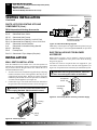
Any noncombustible material may be used for facing (glass, tile, brick, etc.)
as long as the proper clearances are observed (see Clearances, page 5).
IMPORTANT: Louvered openings must not be obstructed, and upper and
lower panels must remain removable for servicing. Use only heat-resistant,
noncombustible mortar or adhesive when securing facing material.
Note: Combustible material, such as wood, that has been fireproofed
is not considered noncombustible.
CORRECT
Long, Blue Flame with Yellow Tips
INCORRECT
CLOSE SHUTTER
Short, Sharp, Blowing Flame
INCORRECT
OPEN SHUTTER
Long, Uneven, Yellow Flame
Figure 49 - Burner Flame Patterns
For more information, visit www.desatech.com
106918-01B