1
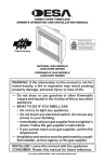
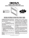
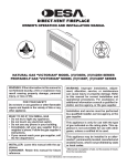
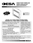
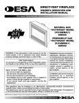
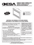
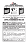
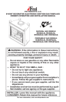
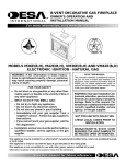
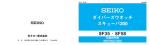
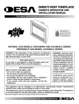
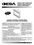
DIRECT-VENT CHASSIS
OWNER’S INSTALLATION INSTRUCTIONS
Patent Pending
MODELS (V)DVC36(B)(H) AND (V)DVC42(B)(H)
For Use with DVM series Burner modules
Installation and service must be performed by a qualified installer, service agency or the gas supplier.
WARNING: Improper installation, adjustment, alteration, service or maintenance can cause injury or property damage. Refer to this manual for correct installation
and operational procedures. For assistance or additional information consult a qualified installer, service
agency or the gas supplier.
This appliance may be installed in an aftermarket,* permanently located, manufactured (mobile) home, where
not prohibited by local codes.
* Aftermarket: Completion of sale, not for purpose of resale, from the manufacturer
State of Massachusetts: The installation must be made
by a licensed plumber or gas fitter in the Commonwealth
of Massachusetts.
INSTALLER: Leave this manual with the appliance.
CONSUMER: Retain this manual for future reference.
For more information, visit www.desatech.com
Table of Contents
Safety Information................................................ 2
Local Codes......................................................... 3
Product Identification............................................ 3
Product Features.................................................. 3
Pre-Installation Preparation.................................. 4
Location of Termination Cap................................. 6
Venting Installation Instructions............................ 7
Replacement Parts............................................. 16
Technical Service............................................... 17
Accessories........................................................ 17
Illustrated Parts Breakdown and Parts List........ 18
Warranty Information............................Back Cover
Safety Information
IMPORTANT: Read this owner’s
manual carefully and completely
before trying to assemble, operate
or service this fireplace. Improper
use of this fireplace can cause
serious injury or death from
burns, fire, explosion, electrical
shock and carbon monoxide
poisoning.
WARNING: Any change to
this fireplace or it’s controls can
be dangerous. Do not modify
this fireplace under any circumstances. Any parts removed for
servicing must be replaced prior
to operating fireplace.
WARNING: Do not use a blower insert, heat exchanger insert or
other accessory not approved for
use with this fireplace.
WARNING: Do not allow fans
to blow directly into the fireplace.
Avoid any drafts that alter burner
flame patterns.
Due to high temperatures, the
appliance should be located out
of traffic and away from furniture
and draperies.
Do not place clothing or other
flammable material on or near
the appliance. Never place any
objects on the appliance.
Do not use this fireplace to cook
food or burn paper or other flammable material.
This fireplace reaches high temperatures. Keep children and
adults away from hot surface to
avoid burns or clothing ignition.
Fireplace will remain hot for a time
after shutdown. Allow surface to
cool before touching.
Carefully supervise young children when they are in the room
with fireplace.
Keep the area around your
fireplace clear of combustible
materials, gasoline and other
flammable vapor or liquids. Do
not run fireplace where these
are used or stored.
1. Never install the fireplace
• in a recreational vehicle
• in windy or drafty areas where curtains or
other combustible (flammable) objects can
make contact with the fireplace front
• in high traffic areas
2. Turn appliance off and let cool before servicing, installing or repairing. Only a qualified
service person should install, service or repair
this fireplace. Have fireplace inspected annually by a qualified service person.
www.desatech.com
118197-01C
Safety information
Continued
3. You must keep control compartments, burners and circulating air passages clean. More
frequent cleaning may be needed due to excessive lint and dust from carpeting, bedding
material, etc. Turn off the gas valve and pilot
light before cleaning fireplace.
4. Have venting system inspected annually by
a qualified service person. If needed, have
venting system cleaned or repaired.
5. Do not use any solid fuels (wood, coal, paper,
cardboard, etc.) in this fireplace. Use only the
gas type indicated on fireplace nameplate.
6. This appliance, when installed, must be electrically grounded in accordance with local codes
or, in the absence of local codes, with the
National Electrical Code, ANSI/NFPA 70 or
the Canadian Electrical Code, CSA C22.1.
7. Do not use fireplace if any part has been exposed to or under water. Immediately call a
qualified service person to arrange for replacement of the unit.
8. Do not operate fireplace if any log is broken.
9. Do not operate fireplace with glass door
removed, cracked or broken.
10. Provide adequate clearances around air
openings.
Local Codes
Install and use fireplace with care. Follow all local
codes. In the absence to local codes, use the current National Fuel Gas Code ANSI Z223.1/NFPA
54* (USA) or the current CSA-B149.1 Installation
Code (Canada).
*Available from:
American National Standards Institute, Inc.
1430 Broadway
New York, NY 10018
National Fire Protection Association, Inc.
Batterymarch Park
Quincy, MA 02269
118197-01C
Product
Identification
Upper Louver
Panel
Flue Collar
Nailing
Flange
Glass Door
Assembly
Lower Louver
Panel
Switch Bracket for Optional
Remote and Blower
Figure 1 - Direct-Vent Fireplace
Product Features
These are a few facts that can help you understand
and enjoy your direct-vent fireplace:
• The venting system may be routed to the outside of your home in several ways. It may vent
through the roof (vertical) or it may vent to an
outside/exterior wall (horizontal). The vent
pipe installation is very important to allow for
proper operation. You must follow the venting
instructions very carefully for either vertical or
horizontal applications.
• This fireplace may be installed in any room of
your house provided all local codes and these
installation instructions are followed.
• This fireplace requires a wall switch, hand-held
remote or wall thermostat (millivolt) for operation (see Accessories, page 42).
• The use of a blower requires electricity if
installed. If you plan to install the blower at a
later date, outlet at bottom of fireplace must be
wired during framing.
• Your direct-vent gas fireplace system (fireplace
and venting) is a balanced and sealed gas operating unit. It requires approximately 10-20
minutes of operating time before the flame
pattern stabilizes.
www.desatech.com
Pre-Installation
Preparation
Location and space
requirements
Determine the safest and most efficient location
for your DESA direct-vent fireplace. Make sure
that rafters and wall studs are not in the way of the
venting system. Choose a location where the heat
output is not affected by drafts, air conditioning
ducts, windows or doors. Figure 2 shows some
common locations. Be aware of all restrictions and
precautions before deciding the exact location for
your fireplace and termination cap.
When deciding the location of your fireplace,
follow these rules:
• Do not connect this fireplace venting to a chimney flue serving a separate solid-fuel burning
fireplace or appliance.
• Due to high temperatures, do not locate this
fireplace in high traffic areas, windy or drafty
areas or near furniture or draperies.
• Proper clearances must be maintained.
• If your fireplace is to be installed directly on
carpeting, vinyl tile or any combustible material other than wood, it must be installed on a
metal or wood panel extending the full width
and depth of the fireplace. See Figure 3.
• Your fireplace is designed to be used in zero
clearance installations. Wall or framing material
can be placed directly against any exterior surface on the back, sides or top of your fireplace,
except where standoff spacers are integrally
attached. If standoff spacers are attached to your
fireplace, these spacers can be placed directly
against wall or framing material. See framing
details on page 5.
• If you plan on installing a television or entertainment center recessed above your fireplace, it
is recommended that you maintain a minimum
18" above top of louver opening.
• When locating termination cap, it is important
to observe the minimum clearances shown in
Figure 7, page 8.
• If recessing into a wall, you can avoid extra
framing by positioning your fireplace against
an already existing framing member.
• Do not recess termination cap into a wall or
siding.
• You may paint the termination cap with 450ºF
heat-resistant paint to coordinate with the exterior finish.
• There must not be any obstruction such as
bushes, garden sheds, fences, decks or utility buildings within 24" from the front of the
termination cap.
• Do not locate termination cap where excessive
snow or ice build up may occur. Be sure to
clear vent termination area after snow falls to
prevent accidental blockage of venting system.
When using snow blowers, do not direct snow
towards vent termination area.
Flush with a wall
Through exterior wall
enclosed in a chase
Corner
installation
Figure 2 - Common Fireplace Locations
21 1/8" (36")
23 1/4" (42")
29" (36")
1
36RW
/4" (42")
D
41" (36")
FW
48"
(42")
Figure 3 - Fireplace Bottom Dimensions
Clearances
Minimum clearances to combustibles for the fireplace are as follows:
*Back and sides
0"
Perpendicular walls
6"
Floor
0"
Ceiling to louver opening 42"
Front
36"
Top of Standoffs
0"
Vent
(See venting instructions for
specific venting clearances.)
Combustible material with a maximum thickness of 5/8" may be flush with the top front of
fireplace.
* For back and sides of fireplace, do not pack
with insulation or other materials. Zero inch
clearance to combustible materials are for framing purpose only.
www.desatech.com
118197-01C
Pre-Installation
Preparation
Continued
B
15"
C 5/8"
49
D 3
10
/8"
35 / "
A3 4
NOTICE: This fireplace is intended for use as supplemental
heat. Use this fireplace along with
your primary heating system. Do
not install this fireplace as your
primary heat source. If you have a
central heating system, you may
run system’s circulating blower
while using fireplace. This will
help circulate the heat throughout the house. In the event of a
power outage, you can use this
fireplace as a heat source.
133/4"
E
F
41"
1
G /4"
41
68 / "
36" Models
1
C
58
/2"
D 1
13
/2"
21B5/8"
41 / "
A5 8
163/4"
F
48"
48G1/4"
E
framing and finishing
Figure 4 shows typical framing of this fireplace.
Figure 5 shows framing for corner installation. All
minimum clearances must be met.
For available accessories for this fireplace, see
Accessories on page 17. If you are using a separate combustible mantel piece, refer to Figure 6
for proper installation height. You can install
noncombustible mantels at any height above the
fireplace.
Note: Noncombustible mantels may discolor!
Nailing
Nailing Tabs
Tabs
H1 2
Nailing
Tabs
Nailing Tabs
81H1/2"
42" Models
Figure 5 - Framing Clearances for Corner
Installation
1
2
3
A
4
B
Wall
5
C
D
6
E
7
F
G
Top of Louver
Opening
361/8" (36")
401/8" (42")
411/4" (36")
481/4" (42")
21" Hor. Vent
Ref.
241/2" Vert. Vent 36"
1
2
42" 23"1 Hor. Vent
3
26 /2" Vert. Vent
Figure 4 - Framing Clearances for
Installation Against an Exterior Wall
4
5
6
7
Mantel Depth
14"
12"
10"
8"
6"
4"
2"
Ref.
A
B
C
D
E
F
G
Mantel from
Top of Louver
Opening
16"
14"
12"
10"
8"
6"
4"
Figure 6 - Clearances for Combustible
Mantels
118197-01C
www.desatech.com
Location of Termination Cap
N
N
D
H
V
L
E
B
C
Fixed
Closed
F
B
Openable Fixed
Closed
V
Openable
V
I
V
G
B
V
B
B
J
V
G
X
G
M
A
V
K
X
V
A
V TERMINATION CAP
X AIR SUPPLY INLET
G GAS METER
RESTRICTED AREA
(TERMINATION PROHIBITED)
A = clearance above grade, veranda, porch, deck, or
I = clearance to service regulator vent outlet [*72" (182.9 cm)
balcony [*12" (30.5 cm) minimum]
minimum]
B = clearance to window or door that may be opened
J = clearance to non-mechanical air supply inlet to building
[6" (15 cm) min. for 10,000 Btu or less; 9" (23 cm) in US
or the combustion air inlet to any other fireplace
if between 10,000 and 50,000, 12" (30 cm) in Canada
[6" (15 cm) min. for 10,000 Btu or less; 9" (23 cm) in US
if between 10,000 and 100,000; 12" (30 cm) in US if
if between 10,000 and 50,000, 12" (30 cm) in Canada
greater than 50,000, 36" (91 cm) in Canada if greater
if between 10,000 and 100,000; 12" (30 cm) in US if
than 100,000]
greater than 50,000, 36" (91 cm) in Canada if greater
C = clearance to permanently closed window
than 100,000]
[minimum 12" (30.5 cm) recommended to prevent
K = clearance to a mechanical air supply inlet [*In Canada,
condensation on window]
6 ft. (1.83m) minimum; In US 3 ft. (91 cm) above if within
D = vertical clearance to ventilated soffit located above the
10 ft. (3 m) horizontally]
terminal within a horizontal distance of 24" (61 cm) from L = † clearance above paved side-walk or a paved driveway
the center-line of the terminal [18" (45.7 cm) minimum]
located on public property [*84" (213.3 cm) minimum]
E = clearance to unventilated soffit [12" (30.5 cm) minimum] M = clearance under veranda, porch, deck
F = clearance to outside corner (see below)
[*12" (30.5 cm) minimum ‡]
G = clearance to inside corner (see below)
N = clearance above a roof shall extend a minimum of
H = *not to be installed above a meter/regulator assembly
24" (61 cm) above the highest point when it passes
within 36" (91.4 cm) horizontally from the center line
through the roof surface and any other obstruction within
of the regulator
a horizontal distance of 18" (45.7 cm)
† vent shall not terminate directly above a side-walk or paved driveway which is located between two
single family dwellings and serves both dwellings*
‡ only permitted if veranda, porch, deck or balconey is fully open on a minimum of 2 sides beneath the floor*
*
as specified in CAN/CSA B149 (.1 or .2) Installation Codes (1991) for Canada and U.S.A.
Note: Local codes or regulations may require different clearances
Termination Clearances for Buildings with Combustible and Noncombustible Exteriors
Inside Corner
Outside Corner
Recessed Location
D
C
A
C
E
A = 6" (15.2 cm)
V
V
V
B = 6" (15.2 cm)
B
Balcony with No Side Wall
Balcony with Perpendicular Side Wall
H
G
V
V
J
G = 12" (30.5 cm) minimum clearance
Combustible &
Noncombustible
H = 24" (61 cm)
J = 20" (50.8 cm)
C = Maximum depth of 48" (121.9 cm)
for recessed location
D = Minimum width for back wall of
recessed location Combustible - 38" (965 mm)
Noncombustible - 24" (61 cm)
E = Clearance from corner in
recessed locationCombustible - 6" (15.2 cm)
Noncombustible - 2" (5.1 cm)
Figure 7 - Minimum Clearances for Termination Cap
www.desatech.com
118197-01C
Venting Installation
Instructions
NOTICE: Read these instructions completely before attempting installation.
These models are tested and approved for use
with DESA (direct-vent) pipe components and
terminations.
The venting system must terminate on the outside of
the structure and can not be attached to a chimney
or flue system serving a separate solid fuel or gas
burning appliance. A direct-vent appliance must
have its own venting system. DO NOT common
vent this appliance.
These models are approved to be vented either
horizontally through an outside wall or vertically
through a roof or chase enclosure using the following guidelines:
• When venting system terminates horizontally
on an outside wall, you may install a standoff
if the termination cap is to be installed directly
on a combustible finish such as vinyl, wood,
stucco, etc.
• Never run the vent downward as this may
cause excessive temperatures which could
cause a fire.
• Vent pipe air space clearances to combustibles
are 1" on all sides except on the horizontal
sections, which requires 2" clearance from
the top of the pipe. Where the termination cap
penetrates a combustible wall, 1" air space
clearance is required.
• Snorkel terminations are required when
minimum clearance to grade cannot be met (see
Figure 16 on page 11).
• Have fireplace and selected vent components on
hand to help determine the exact measurements
when elbowing or offsetting. Always use wall
firestops when penetrating walls and firestops
when penetrating ceilings or attic spaces.
• If using a venting configuration of only horizontal venting with no vertical run, a 1/4" rise
for every 12" of run toward the termination is
required.
• For installation of fireplace at elevations of 4000
feet or greater, pay special attention to venting
requirement recommendations.
118197-01C
WARNING: Read all instructions completely and thoroughly
before attempting installation.
Failure to do so could result in
serious injury, property damage
or loss of life.
NOTICE: Failure to follow these instructions will void the warranty.
NOTICE: Do not seal termination
cap to vent pipe. Cap must be
removable for vent inspection
and maintenance.
Installation Precautions
• Wear gloves and safety glasses for protection
• Use extreme caution when using ladders or
when on roof tops
• Be aware of electrical wiring locations in walls
and ceilings
The following actions will void the warranty on
your venting system:
• Installation of any damaged venting component
• Unauthorized modification of the venting system (Do not cut or alter vent components)
• Installation of any component part not manufactured or approved by DESA
• Installation other than as instructed by these
instructions
WARNING: This gas fireplace
and vent assembly must be vented
directly to the outside. The venting
system must NEVER be attached
to a chimney serving a separate
solid fuel burning appliance. Each
direct-vent gas appliance must
use a separate vent system. Do not
use common vent systems.
WARNING: Vent pipe air
space clearances to combustibles
are 1" on all sides except on the
horizontal sections, which require
2" clearances from the top of the
pipe. Where the termination cap
penetrates a combustible wall, 1"
air space clearance is required.
www.desatech.com
Venting Installation
instructions
Continued
INSTALLATION PLANNING
There are two basic types of direct-vent installation:
• Horizontal Termination
• Vertical Termination
Horizontal Termination Installation
IMPORTANT: Horizontal square terminations
require only inner portion of wall firestop. Horizontal installations using round termination require
exterior portion of wall firestop (see Figure 14,
page 10.
1. Set the fireplace in its desired location and determine the route your horizontal venting will take.
Do not secure the fireplace until all venting has
been installed. Some installations require sliding
the fireplace in and out of position to make final
venting connections. Figures 14 through 18 on
pages 10 through 12 show different configurations for venting with horizontal termination that
will help you decide which application best suits
your installation. Check to see if wall studs or
roof rafters are in the path of your desired venting route. If they are, you may want to adjust the
location of the fireplace.
2. Direct vent pipe sections and components are
designed with special twist-lock connections.
Twist-Lock Procedure: The female ends of the
pipes have locking lugs (indentations). These
lugs will slide straight into matching slots on
the male ends of adjacent pipes. Push pipe sections together and twist one section clockwise
approximately one-quarter turn until the sections
are fully locked (see Figure 8). Note: Horizontal
runs of vent must be supported every three feet.
Use wall straps for this purpose.
3. Use a 45° elbow to connect venting system
to fireplace flue collar. The elbow is designed
to be twist-locked onto the flue collar as
described in step 2. IMPORTANT: Do not
attempt to alter the configuration of the elbow
by cutting, twisting, bending, etc.
4. Assemble the desired combination of pipe and
elbows to the fireplace flue collar. If there are
long portions of venting run, pre-assembled
pipe sections may be installed as subassemblies for convenience.
5. Carefully determine the location where the vent
pipe assembly will penetrate the outside wall.
The center of the hole should line up with the
center-line of the horizontal vent pipe. Mark the
wall for a 10 3/4" x 10 3/4" square hole. Cut and
frame the square hole in the exterior wall where
the vent will be terminated. If the wall being
penetrated is constructed of noncombustible
material, such as masonry block or concrete,
a 8 1/2" hole with zero clearance is acceptable
(see Figure 9).
Female
Locking
Lugs
Male
Slots
Figure 8 - Vent Pipe Connections
Vent Opening
Combustible Wall
10 3/4" Inside Framing
10 3/4"
10 3/4"
Vent Opening
Noncombustible Wall
(Framing
Detail)
8 1/2"
Center of
Hole
Figure 9 - Vent Opening Requirements
www.desatech.com
118197-01C
Venting Installation
instructions
Continued
Vent Cap
WARNING: Do not recess
vent termination into any wall.
This will cause a fire hazard.
6. Noncombustible Exterior Wall: Position the
horizontal vent cap in the center of the 8 1/2"
round hole and attach to the exterior wall with
four wood screws provided. Before attaching
the vent cap to exterior wall, run a bead of
non-hardening mastic (pliable sealant) around
the outside edges to make a seal between it and
the outside wall. Note: The four wood screws
provided should be replaced with appropriate
fasteners for stucco, brick, concrete or other
types of sidings.
Combustible Exterior Wall: For vinyl siding,
stucco or wood exteriors, a siding standoff may
be installed between the vent cap and exterior
wall. The siding standoff prevents excessive
heat from damaging the siding materials.
Siding material must be cut to accommodate
standoff. Bolt the vent cap to the standoff. Apply non-hardening mastic around outside edge
of standoff. Position the standoff/cap assembly
in the center of the 10 3/4" square hole and attach
to exterior wall with wood screws provided (see
Figure 11). The siding standoff must sit flush
against the exterior fascia material.
7. Combustible Exterior Wall Only: Slide the wall
firestop over the vent pipe before connecting
horizontal run to vent cap (see Figure 12).
8. Carefully move fireplace, with vent assembly
attached, toward wall and insert vent pipe
into horizontal termination. The pipe overlap
should be a minimum of 11/4" (see Figure 13,
page 10).
9. Combustible Exterior Wall Only: Slide wall
firestop against interior wall surface and attach
with screws provided. See Figure 13, page 10,
for horizontal termination details.
10. Place fireplace into position and shim with
noncombustible material if needed. Nail or
screw side flanges to framing to secure unit in
place. IMPORTANT: Make sure fireplace is
level before securing. If fireplace is not level
it will not work properly.
118197-01C
Wood Screw
Figure 10 - Installing Horizontal Vent Cap
(Noncombustible Exterior)
Cut Siding Away to
Fit Standoff
Standoff
Wood
Screw
Vent
Cap
Apply Mastic
to All Four Sides
Screws
Figure 11 - Installing Siding Standoff
(Combustible Exterior Wall)
Interior Wall
Surface
Wall
Firestop
Vent Cap
(Horizontal
Termination)
Horizontal
Vent Pipe
Figure 12 - Connecting Vent Cap with
Horizontal Vent Pipe
www.desatech.com
Screw
Venting Installation
instructions
Continued
Minimum Pipe
Overlap 11/4"
Direct-Vent
Pipe
Siding Standoff
Screws
Wall
Firestop
GROUND FLOOR INSTALLATION
Recommended Applications:
• Installation using cabinet surrounds
• Through the wall using round or square termination (up to 12" horizontal pipe)
• NOT FOR CORNER INSTALLATION
Adjustable
Horizontal Pipe 12" Max.
High Wind
Square
Termination
45° Elbow
Wall Firestop
Maintain 1"
Minimum Air
Space Around
Outer Pipe When
Penetrating a Wall
High Wind
Termination
Apply
Mastic to
Outside
10 3/4" x 10 3/4"
Edge of
Framed Opening
Standoff
Exterior Wall with Vinyl Siding
Figure 13 - Typical Horizontal
Termination Cap Mounting with
Additional Siding Standoff Installed
Square Termination
WARNING: Never run vent
downward as this may cause
excessive temperatures which
could cause a fire. Operation of
improperly installed and maintained venting system could
result in serious injury, property
damage or loss of life.
10
Horizontal (H)
32 3/4" min.
17" max.
45° Elbow
Wall
Firestop
Horizontal Termination Configurations
Figures 14 through 18 show different configurations and alternatives for venting with horizontal
termination. Each figure includes a chart with
critical minimum and maximum dimensions which
MUST be met. IMPORTANT: If using a venting
configuration of only horizontal venting with no
vertical run, a 1/4" rise for every 12" of run toward
the termination is required.
NOTICE: Do not seal termination
cap to vent pipe. Cap must be
removable for vent inspection
and maintenance.
Vertical (V)
Exterior Portion
of Wall Firestop
(Round
Termination
Only)
Horizontal
Round
Termination
Round
Termination
* If installing this fireplace at altitudes of
4000 feet and above, it is recommended
that an additional vertical height of 6" be
added to the vent system.
Figure 14 - Horizontal Termination
Configuration for Square or Round
Terminations
www.desatech.com
118197-01C
Venting Installation instructions
Continued
CORNER INSTALLATION
Recommended Applications:
• Corner ground floor installation
• Ground floor installation where pipe vents horizontally through wall (over 12" horizontal pipe)
• Basement installation where one foot clearance
from ground to termination is possible
Not to Exceed (H) Limits 90° Elbow
Square
Termination
Not to Exceed
(H) Limits
90° Elbow
Wall
Firestop
As Required
for (V), See
Chart for
Pipe Section
Required
Square
Termination
12" Min.
45° Elbow
Wall
Firestop
Vertical (V)
Required
Vertical Pipe
Horizontal (H)
*43 1/2" min.
54 1/2" min.
66 1/2" min.
78 1/2" min.
90 1/2" min.
None
1 ft.
2 ft.
3 ft.
4 ft.
30" max.
48" max.
60" max.
84" max.
20' max.
45° Elbow
* Ground Floor Corner Venting
Figure 15 - Horizontal Termination Configuration for Corner Installation Using One
90° Elbow
SNORKEL TERMINATION INSTALLATION
Recommended Applications:
• Installations requiring a vertical rise on building exterior
• Any installation using snorkel termination to achieve one foot above ground
Snorkel terminations are available for installations requiring a vertical rise on the exterior of the building.
If installing snorkel termination below grade, you must provide proper drainage to prevent water from
entering snorkel termination (see Figure 16). Do not back fill around snorkel termination.
Snorkel
Termination
Wall
Snorkel Termination
Firestop
Snorkel Termination
90° Elbow
12" Min.
12" Min.
12"
Min.
45° Elbow
Adequate
Drainage
Figure 16 - Snorkel Termination Configurations for Below Ground Installation
118197-01C
www.desatech.com
11
Venting Installation instructions
Continued
HORIZONTAL SYSTEM INSTALLATION
USING TWO 90° ELBOWS
The following configurations show the minimum
vertical rise requirements for a horizontal system
using two 90° elbows.
45° Elbow
Venting with Two 90° Elbows
Horizontal (H1) +
Vertical (V) Horizontal (H1)
Horizontal (H2)
5' min.
6' min.
7' min.
8' min.
20' max.
2' max.
4' max.
6' max.
8' max.
8' max.
6' max.
12' max.
18' max.
20' max.
20' max.
Figure 17 - Horizontal Termination Configuration for Venting Using Two 90° Elbows
Venting with Two 90° Elbows
Horizontal (H1) +
Horizontal (H2)
Vertical (V)
5' min.
6' min.
7' min.
8' min.
20' max.
6' max.
12' max.
18' max.
20' max.
20' max.
45° Elbow
Figure 18 - Horizontal Termination Configuration for Venting Using Two 90° Elbows
with Termination at 90° with Fireplace
12
www.desatech.com
118197-01C
Venting Installation
instructions
Continued
installation for vertical
termination
Note: Vertical restrictor must be installed in all
vertical installations.
1. Determine the route your vertical venting
will take. If ceiling joists, roof rafters or other
framing will obstruct the venting system,
consider an offset (see Figure 19) to avoid cutting load bearing members. Note: Pay special
attention to these installation instructions for
required clearances (air space) to combustibles
when passing through ceilings, walls, roofs,
enclosures, attic rafters, etc. Do not pack air
spaces with insulation. Also note maximum
vertical rise of the venting system and any
maximum horizontal offset limitations.
2. Set the fireplace in desired location. Drop a
plumb line down from the ceiling to the position of the fireplace exit flue. Mark the center
point where the vent will penetrate the ceiling.
Drill a small locating hole at this point.
Drop a plumb line from the inside of the roof
to the locating hole in the ceiling. Mark the
center point where the vent will penetrate the
roof. Drill a small locating hole at this point.
Roof Flashing
Wall Strap
Flat Ceiling Installation
1. Cut a 10 3/4" square hole in the ceiling using
the locating hole as a center point. The opening
should be framed to 10 3/4" x 10 3/4" (27.3 cm x
27.3 cm) inside dimensions, as shown in Figure
9 on page 8 using framing lumber the same
size as the ceiling joists. If the area above the
ceiling is an insulated ceiling or an attic space,
nail firestop from the top side. This prevents
loose insulation from falling into the required
clearance space. If the area above the ceiling is
a living space, install firestop below the framed
hole. The firestop should be installed with no
less than three nails per side (see Figure 20).
2. Assemble the desired lengths of pipe and
elbows necessary to reach from the fireplace
flue up through the firestop. Be sure all pipe
and elbow connections are fully twist-locked
(see Figure 8, page 8).
3. Cut a hole in the roof using the locating hole
as a center point. (Cover any exposed open
vent pipes before cutting hole in roof.) The
10 3/4" x 10 3/4" hole must be measured on
the horizontal; actual length may be larger
depending on the pitch of the roof. There
must be a 1" clearance from the vent pipe to
combustible materials. Frame the opening as
shown in Figure 9, page 8.
4. Connect a section of pipe and extend up
through the hole.
Note: If an offset is needed to avoid obstructions, you must support the vent pipe every 3
feet. Use wall straps for this purpose (see Figure 19). Whenever possible, use 45° elbows
instead of 90° elbows. The 45° elbow offers
less restriction to the flow of the flue gases
and intake air.
If area above is an attic space or insulated
area, install firestop above framed hole.
45° Elbow
If area above is a living space, install
firestop below framed hole.
Ceiling Firestop
Figure 19 - Offset with Wall Strap and 45°
Elbows
Figure 20 - Installing Firestop
118197-01C
www.desatech.com
13
Venting Installation
instructions
Continued
5. Place the flashing over the pipe section(s)
extending through the roof. Secure the base of
the flashing to the roof and framing with roofing nails. Be sure roofing material overlaps the
top edge of the flashing as shown in Figure 19,
page 13. There must be a 1" clearance from
the vent pipe to combustible materials.
6. Continue to add pipe sections until the height
of the vent cap meets the minimum building
code requirements described in Figure 7 on
page 6. Note: You must increase vent height
for steep roof pitches. Nearby trees, adjoining
rooflines, steep pitched roofs and other similar
factors may cause poor draft or down-drafting
in high winds. Increasing the vent height may
solve this problem.
7. Twist-lock the vent cap onto the last section
of vent pipe.
Note: If the vent pipe passes through any occupied
areas above the first floor, including storage spaces
and closets, you must enclose pipe. You may
frame and sheetrock the enclosure with standard
construction material. Make sure and meet the
minimum allowable clearances to combustibles.
Do not fill any of the required air spaces with
insulation.
Vertical Termination Configurations
Figures 21 through 24 show four different configurations for vertical termination.
Venting with Two 90° Elbows
Horizontal (H1) +
Vertical (V)
Horizontal (H2)
5' min.
6' min.
7' min.
8' min.
20' max.
2' max.
4' max.
6' max.
8' max.
8' max.
45° Elbow
Note: Install restrictor
into inner collar of
fireplace as shown.
Figure 21 - Vertical Venting
Configuration Using Two 90° Elbows
with Two Horizontal Runs (Vertical
Round High Wind Termination Shown)
Venting with One 90° Elbow
Vertical (V)
Horizontal (H)
5' min.
6' min.
7' min.
8' min.
20' max.
2' max.
4' max.
6' max.
8' max.
8' max.
45° Elbow
Note: Install restrictor into
inner collar of fireplace as
shown.
Figure 22 - Vertical Venting
Configuration Using One 90° Elbow
(Vertical Round High Wind Termination
Shown)
14
www.desatech.com
118197-01C
Venting Installation
instructions
Continued
Vertical Venting
V = 40' max.
Note: Install
restrictor into
inner collar of
fireplace as
shown.
45° Elbow
45° Elbow
Venting with Two 90° Elbows
Vertical (V1)
Horizontal (H)
5' min.
6' min.
7' min.
8' min.
Note: Install
restrictor into
inner collar of
fireplace as
shown.
6' max.
12' max.
18' max.
20' max.
Figure 24 - Vertical Venting
Configuration With No Horizontal Run
(Vertical Round High Wind Termination
Shown)
Note: Vertical (V1) + Vertical (V2) = 40' max.
Figure 23 - Vertical Venting
Configuration Using Two 90° Elbows
(Vertical Round High Wind Termination
Shown)
118197-01C
www.desatech.com
15
Venting Installation
instructions
Continued
parts list for venting kits
and components
DESA (5"/8") Pipe & Vent Kits
Number Description
P58-6
6" Section Double Wall Pipe,
Galvanized
P58-12 12" Section Double Wall Pipe,
Galvanized
P58-2424" Section Double Wall Pipe,
Galvanized
P58-36 36" Section Double Wall Pipe,
Galvanized
P58-48 48" Section Double Wall Pipe,
Galvanized
PA58-712 Adjustable 7"-12" Section Double
Wall Pipe, Galvanized
E58-45 45° Elbow, Galvanized
E58-90 90° Elbow, Galvanized
VKG-58 Ground Floor Vent Kit, Galvanized
(Includes: 45° Elbow, 7"-12"
Adjustable Pipe, Wall Firestop,
Horizontal Square Termination,
16 Screws)
VKB-58 Basement Vent Kit, Galvanized
(Includes: 45° Elbow, 7"-12"
Adjustable Pipe, Wall Firestop,
Horizontal Square Termination,
4' Pipe, 90° Elbow, 20 Screws)
VKS-58 Snorkel Vent Kit, Galvanized
(Includes: 45° Elbow, 7"-12"
Adjustable Pipe, Wall Firestop,
36" Snorkel Termination, 4' Pipe,
1' Pipe, 90° Elbow, 26 Screws)
VKR-58 R o o f Ve n t K i t , G a l v a n i z e d
(Includes: 45° Elbow, 7"-12"
Adjustable Pipe, Flue Restrictor,
Vertical High Wind Termination,
2' Pipe, 4' Pipe, Wall Firestop,
Storm Collar, Roof Flashing
[0/12 - 6/12], 26 Screws)
VKC-58 Corner Vent Kit, Galvanized
(Includes 45° Elbow, 7"-12"
Adjustable Pipe, Wall Firestop,
Horizontal Termination, 6" Pipe,
90° Elbow, 18 Screws)
HHTK-58 High Wind Round Horizontal
Termination Kit
(Includes Round Termination,
Wall Firestop, 45° Elbow)
16
Number
HHT-58
HTS-58
HTKS-58
VT-58
ST-58-14
ST-58-36
SC-58
WF-58
RF-58-6
RF-58-12
VR-58
S-58
WS-58
CS-58
FP-58
SF-58
RF-58
Description
High Wind Round Horizontal
Termination Kit, Galvanized
Horizontal Square Termination,
Galvanized
Horizontal Square Termination Kit
(Includes: Square Termination,
Wall Firestop, 45° Elbow)
Vertical Round Termination,
Galvanized
14" Snorkel Termination,
Galvanized
36" Snorkel Termination,
Galvanized
Storm Collar, Galvanized
Wall Firestop, Galvanized
Roof Flashing - 0 to 6/12 Pitch,
Galvanized
Roof Flashing - 6/12 to 12/12 Pitch,
Galvanized
Vertical Restrictor, Galvanized
Vinyl Siding Standoff,
Galvanized
Wall Strap
Cathedral Ceiling Support
Firestop Plate
Stucco Flashing For use with HTS-58
Flat Roof Flashing
Replacement Parts
Note: Use only original replacement parts. This
will protect your warranty coverage for parts
replaced under warranty.
Parts Under Warranty
Contact authorized retailers of this product. If
they can not supply original replacement part(s),
call DESA’s Customer Service Department at
1-866-672-6040.
When calling DESA, have ready
• your name
• your address
• model and serial numbers of your fireplace
• how fireplace was malfunctioning
• type of gas used (propane/LP or natural gas)
• purchase date
Usually, we will ask you to return the part to the
factory.
www.desatech.com
118197-01C
Replacement Parts
Continued
Parts Not Under Warranty
Contact authorized retailers of this product. If
they can not supply original replacement part(s),
call DESA at 1-866-672-6040 for referral information.
When calling DESA, have ready
• model number of your fireplace
• the replacement part number
Technical Service
You may have further questions about installation,
operation or troubleshooting. If so, contact DESA’s
Customer Service Department at 1-866-672-6040.
When calling, please have your model and serial
numbers of your heater ready.
You can also visit DESA’s technical service web site at
www.desatech.com.
Accessories
Notice: All accessories may
not be available for all fireplace
models.
Purchase these fireplace accessories from your local
retailer. If they can not supply these accessories,
call DESA’s Sales Department at 1-866-672-6040
for information. You can also write to the address
listed on the back page of this manual.
Brick Liner Kit
(Not Shown)
BL36DA - Textured Refractory
BL36DSA - Standard Refractory
BL36DHA - Textured Refractory Herringbone
BL36DHSA - Standard Refractory Herringbone
BL42DA - Textured Refractory
BL42DSA - Standard Refractory
BL42DHA - Textured Refractory Herringbone
BL42DHSA - Standard Refractory Herringbone
This brick liner adds a touch of style to your directvent fireplace. Complete installation instructions
included in this manual.
Face/Louver Panel kit
(Not Shown)
118197-01C
FPD36 - Filigree, Black
FPD36B - Filigree, Brushed Brass
FPD36P - Filigree, Platinum
FPD36PB - Filigree, Polished Brass
RLD42 - Rolled Louver, Black
FPD42 - Filigree, Black
FPD42B - Filigree, Brushed Brass
FPD42P - Filigree, Platinum
FPD42PB - Filigree, Polished Brass
Louver trim kit
(Rolled Louvers Only) (Not Shown)
LT36B - Brushed Brass
LT36P - Platinum
LT36PB - Polished Brass
LT42B - Brushed Brass
LT42P - Platinum
LT42PB - Polished Brass
Deflection hoods
(Not Shown)
HD36 - Black (2" Brow)
HD42 - Black (2" Brow)
Perimeter Trim kit
(Not Shown)
PT36 - Black
PT36B - Brushed Brass
PT36P - Platinum
PT36PB - Polished Brass
PT42 - Black
PT42B - Brushed Brass
PT42P - Platinum
PT42PB - Polished Brass
Manual blower Kit - BK
Manual variable control blower accessory provides
better heat distribution. Complete installation
and operation instructions
included in this manual.
Thermostaticallycontrolled
blower kit - BKT
Provides better heat distribution. Blower turns
off and on automatically, as needed. Complete
installation and operation
instructions included in this
manual.
www.desatech.com
17
Illustrated Parts Breakdown
Models (V)DVC36(B)(H) and (V)DVC42(B)(H)
6
7
8
4
1
9
11
3
10
18
19
12
17
13
2
14
16
15
5
18
www.desatech.com
118197-01C
PARTS LIST
Models (V)DVC36(B)(H) and (V)DVC42(B)(H)
This list contains replaceable parts used in your fireplace. When ordering parts, follow the instructions
listed under Replacement Parts on page 16 of this manual.
KEY
NO.
1
2
3
(V)DVC36(B)(H) (V)DVC42(B)(H) DESCRIPTION
**
**
108010-01
—
108011-01
108011-02
**
**
**
109082-01
24460
See Below
See Below
See Below
108719-01
12105
11418
14123
21171
24353
4
5
6
7
8
9
10
11
12
13
14
15
16
17
18
19
QTY.
1
1
1
1
1
1
1
1
1
1
1
1
1
1
1
2
2
1
2
1
27253
**
Firebox Assembly
**
Face Weldment
108328-01
Door Assembly
108328-02
Door Assembly (V Models Only)
108331-01
Top Louver Assembly
108331-02
Bottom Louver Assembly
**
Fireplace Top
**
Fireplace Top Insulation
**
Fireplace Surround
109082-02
Heat Shield
24460
Gas Conduit Assembly
See Below
Left Refractory Brick Panel
See Below
Rear Refractory Brick Panel
See Below
Right Refractory Brick Panel
108455-01
Screen Rod
107840-01
Screen
11418
Push-On Nut
14123
Strain Relief
21171
Gas Knock-Out Cover
24353
Handy Box Assembly
PARTS AVAILABLE - NOT SHOWN
27253
Notice Label
55240
55240
1
1
Vent Label
REFRACTORY BRICK PANELS
PART NO.
110989-02
111215-02
111299-02
111302-02
110989-01
111215-01
111299-01
111302-01
110991-02
111217-02
111297-02
111330-02
110991-01
111217-01
111297-01
111300-01
110990-02
111216-02
111298-02
111301-02
110990-01
111216-01
111298-01
111301-01
118197-01C
DESCRIPTION
Left Refractory Brick Panel
Left Refractory Brick Panel
Left Refractory Brick Panel
Left Refractory Brick Panel
Left Refractory Brick Panel
Left Refractory Brick Panel
Left Refractory Brick Panel
Left Refractory Brick Panel
Rear Refractory Brick Panel
Rear Refractory Brick Panel
Rear Refractory Brick Panel
Rear Refractory Brick Panel
Rear Refractory Brick Panel
Rear Refractory Brick Panel
Rear Refractory Brick Panel
Rear Refractory Brick Panel
Right Refractory Brick Panel
Right Refractory Brick Panel
Right Refractory Brick Panel
Right Refractory Brick Panel
Right Refractory Brick Panel
Right Refractory Brick Panel
Right Refractory Brick Panel
Right Refractory Brick Panel
DVC
36B
DVC
36H
DVC
42B
DVC
42H
VDV
C36
B
VDV
C36
H
VDV
C42
B
VDV
C42
H
** Part not available for field replacement.
•
•
•
•
•
•
•
•
•
•
•
•
•
•
•
•
•
•
•
www.desatech.com
•
•
•
•
•
QTY
1
1
1
1
1
1
1
1
1
1
1
1
1
1
1
1
1
1
1
1
1
1
1
1
19
Warranty Information
KEEP THIS WARRANTY
Model
Serial No.
Date Purchased
Always specify model and serial numbers when communicating with the factory.
We reserve the right to amend these specifications at any time without notice. The only warranty applicable is our
standard written warranty. We make no other warranty, expressed or implied.
LIMITED WARRANTY
DIRECT-VENT FIREPLACE
DESA warrants this product to be free from defects in materials and components for two (2) years from the date
of first purchase, provided that the product has been properly installed, operated and maintained in accordance
with all applicable instructions. To make a claim under this warranty the Bill of Sale or cancelled check must
be presented.
This warranty is extended only to the original retail purchaser. This warranty covers the cost of part(s) required to
restore this heater to proper operating condition and an allowance for labor when provided by a DESA Authorized
Service Center. Warranty part(s) MUST be obtained through authorized retailers of this product and/or DESA who
will provide original factory replacement parts. Failure to use original factory replacement parts voids this warranty.
The heater MUST be installed by a qualified installer in accordance with all local codes and instructions furnished
with the unit.
This warranty does not apply to parts that are not in original condition because of normal wear and tear or parts
that fail or become damaged as a result of misuse, accidents, lack of proper maintenance or defects caused by
improper installation. Travel, diagnostic cost, labor, transportation and any and all such other costs related to
repairing a defective heater will be the responsibility of the owner.
TO THE FULL EXTENT ALLOWED BY THE LAW OF THE JURISDICTION THAT GOVERNS THE SALE
OF THE PRODUCT; THIS EXPRESS WARRANTY EXCLUDES ANY AND ALL OTHER EXPRESSED
WARRANTIES AND LIMITS THE DURATION OF ANY AND ALL IMPLIED WARRANTIES, INCLUDING
WARRANTIES OF MERCHANTABILITY AND FITNESS FOR A PARTICULAR PURPOSE TO TWO (2)
YEARS ON ALL COMPONENTS FROM THE DATE OF FIRST PURCHASE; AND DESA’S LIABILITY IS
HEREBY LIMITED TO THE PURCHASE PRICE OF THE PRODUCT AND DESA SHALL NOT BE LIABLE
FOR ANY OTHER DAMAGES WHATSOEVER INCLUDING INDIRECT, INCIDENTAL OR CONSEQUENTIAL DAMAGES.
Some states do not allow a limitation on how long an implied warranty lasts or an exclusion or limitation of
incidental or consequential damages, so the above limitation on implied warranties or exclusion or limitation on
damages may not apply to you.
This warranty gives you specific legal rights and you may also have other rights that vary from state to state.
For information about this warranty write:
2701 Industrial Drive
P.O. Box 90004
Bowling Green, KY 42102-9004
www.desatech.com
118197 01
NOT A UPC
118197-01
Rev. C
10/06