1
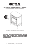
ELECTRIC FIREPLACE/INSERT SAFETY INFORMATION AND INSTALLATION MANUAL Patent No. 7,219,456 B1 Models EL36L, EL36LD AND VE36LBHB PLEASE READ THIS MANUAL BEFORE INSTALLING AND USING APPLIANCE. WARNING: If the information in this manual is not followed exactly, an electrical shock or fire may result causing property damage, personal injury or loss of life. FOR YOUR SAFETY — Do not store or use gasoline or other flammable vapors and liquids in the vicinity of this or any other appliance. — Installation and service must be performed by a qualified service agency. This fireplace meets the construction and safety standards of H.U.D. for application in manufactured homes when installed according to these instructions. INSTALLER: Leave this manual with the appliance. CONSUMER: Retain this manual for future reference. For more information, visit www.desatech.com Table of Contents Safety................................................................... 2 Listing Approvals.................................................. 3 Product Dimensions............................................. 3 Product Identification............................................ 4 Unpacking and Testing......................................... 4 Locating Fireplace................................................ 4 Installation............................................................ 6 Operation.............................................................. 7 Accessory Installation........................................... 8 Cleaning............................................................... 9 Servicing............................................................... 9 Wiring Diagram................................................... 14 Troubleshooting.................................................. 15 Replacement Parts............................................. 16 Technical Service............................................... 16 Accessories........................................................ 17 Parts................................................................... 18 Warranty...............................................Back Cover Safety WARNING: Improper installation, adjustment, alteration, service or maintenance can cause injury or property damage. Refer to this manual. For assistance or additional information, consult a qualified installer. CAUTION: Do not expose the heater to the elements (such as rain, etc). Do not place clothing or other flammable material on or near firebox. Never place any objects on the fireplace. Carefully supervise young children when they are in the room with fireplace. Fireplace becomes very hot when running. Keep children and adults away from hot surfaces to avoid burns or clothing ignition. Fireplace will remain hot for a time after shutdown. Allow surfaces to cool before touching. Do not install fireplace directly on carpet or similar surface which may restrict air circulation beneath unit. When using electrical heaters, basic precautions should always be followed to reduce the risk of fire, electric shock and injury to persons, including the following: 2 1. Read all instructions before using this heater. 2. Keep combustible materials, such as furniture, pillows, bedding, papers, clothes and curtains at least 3 feet (0.9 m) from front of heater. 3. This heater is hot when in use. To avoid burns, do not let bare skin touch hot surfaces. The grill directly in front of heater outlet becomes hot during heater operation. 4. Extreme caution is necessary when any heater is used by or near children or invalids and whenever heater is left operating and unattended. 5. Always unplug heater when not in use. 6. Do not operate any heater with a damaged cord or plug or if heater malfunctions or has been dropped or damaged in any way. Return heater to authorized service facility for examination, electrical or mechanical adjustment or repair. 7. Do not use outdoors. 8. This heater is not intended for use in bathrooms, laundry areas and similar indoor locations. Never locate heater where it may fall into a bathtub or other water container. 9. Do not run cord under carpeting. Do not cover cord with throw rugs, runners or the like. Arrange cord away from traffic area and where it will not be tripped over. 10.To disconnect heater, turn controls to the OFF before removing plug from outlet (turn off power to unit). 11.Do not insert or allow foreign objects to enter any ventilation or exhaust opening as this may cause an electric shock or fire or damage the heater. 12.To prevent possible fire, do not block air intakes in any manner. Do not use on soft surfaces, like a bed, where openings may become blocked. 13.Connect to properly grounded circuits only. www.desatech.com 122663-01D SAFETY Continued 14.A heater has hot and arcing or sparking parts inside. Do not use it in areas where gasoline, paint or flammable liquids or vapors are used or stored. 15.Use this heater only as described in this manual. Any other use not recommended by the manufacturer may cause fire, electric shock or injury to persons. 16. Avoid the use of an extension cord because the extension cord may overheat and cause a risk of fire. However, if you have to use an extension cord, the cord should be No. 14 AWG minimum size and rated not less than 1875 WATTS. 17.Always use ground fault protection where required by electrical codes. 18.Always disconnect power before performing any cleaning, maintenance or relocation of heater. 19.To prevent a possible fire, do not burn wood or other materials in this heater. 20.To prevent electric shock or fire, always use a certified electrician should new circuits or outlets be required. 21.When transporting or storing heater, keep in a dry place. 22.Control panel door gets hot during heater operation. To open control panel door, gently pull on left and right outer edges. Do not open from center of control panel door. Listing Approvals This heater has been tested in accordance with the CSA Standards for fixed and location-dedicated electric room heaters in the United States. All components are UL or CSA safety certified. If you need assistance during installation, please contact your local dealer or the DESA Heating, LLC at 1-866-672-6040. Please have the distributor’s model and serial numbers when you call. Description: Voltage: Watts: Amps: 36" Fireplace 120 / 240 1500 / 3000 15 Amp / 20 Amp Grounded Circuit Note: This heater must be electrically wired and grounded in accordance with local codes or, in the absence of local codes, with National Electric Code ANSI/NFPA 70-latest edition or the Canadian Electric Code, CSA C22.1 as appropriate. Product Dimensions 24 1/4" TOP 17 1/4" 17 5/8" 2 1/8" 5/8" 41" 43" 35" LEFT SIDE 42 1/8" To Nail Location FRONT 31 7/8" 36 1/2" 36 3/4" To Nail Location 37" 21" 361/8" 8" 15 1/8" RIGHT SIDE Figure 1 - Heater Dimensions 122663-01D www.desatech.com 3 Product Identification Control Panel Door Remote Hide Flame Control Ember Control Backlight Control Heat Vents (Behind Door) Front Glass Heater Flame Ember Backlight Power Heater Control ON/OFF Power Button Log Set Magnetic Catch Figure 2 - Product Identification Unpacking and Testing Carefully remove unit from box. Prior to permanently installing unit, test to make sure unit operates properly. Unit does not come with a power cord installed. Unit must be hard wired to either a 120/60 or 240/60 volt supply. CAUTION; The unit must be connected to a properly grounded and protected 120/240 volt circuits. Always use ground fault protection where required by the electrical code. WARNING: Do not operate the unit if it is damaged or has malfunctioned. If you suspect the unit is damaged, return the unit to an authorized service facility for examination, electrical or mechanical adjustment or repair. Locating Fireplace WARNING: Due to high temperatures, this heater should be located out of traffic. Keep combustible materials such as furniture, pillows, bedding, papers, clothes and curtains at least 3 feet (0.9 m) from the front of the heater. WARNING: Never locate this heater where it may fall into a bathtub or other water container. 4 NOTICE: Minimum and maximum clearances must be maintained at all times. Illustrations throughout these instructions reflect typical installations and are for design purposes only. Actual installations may vary slightly due to individual preferences. WARNING: To prevent contact with sagging or loose insulation, the heater must not be installed against vapor barrier or exposed insulation. Localized overheating could occur and a fire could result. www.desatech.com 122663-01D Locating Fireplace Continued Installation INSTALLATION CLEARANCES CAUTION: Do not expose the heater to the elements (such as rain, etc.) CAUTION: Wear gloves and safety glasses for protection during installation and maintenance. Plan where to locate and frame fireplace. Before installation consider the following: 1. Fireplace location must allow for wall and ceiling clearances (see Installation Clearances). 2. Fireplace screen should not be exposed to direct sunlight from windows or doors. 3. Unit can be wired for either 120/60 (15 amp circuit) or 240/60 (20 amp circuit). A dedicated circuit should be provided to avoid circuit breaker trips or blown fuses. Flush Installations are recommended where living space is limited or at a premium. Since space required to enclose fireplace would be located beyond an outside wall, this installation would require additional planning and construction. Check local codes for any restrictions. Projected Installations can extend any distance into room. A projection may be ideal for a new addition on an existing, finished wall. Corner Installations make use of space that may not normally be used and provides a wider and more efficient viewing angle and heat distribution. Internal Wall Installations provide a discrete option for room separation and can also be an ideal addition to an existing wall. Minimum clearances to combustible construction are: Top, Back and Sides of Recessed Cabinet 0" Min. Drywall to Sides of Front Face 0" Min. Framing at Nailing Flanges 0" Min. Ceiling to Opening 36" Min. Floor 0" Min. Front 36" Min. Perpendicular Side Wall 10" Min. Mantel Clearances For mantel clearances see Figures 4 and 5. 12" Ref. 10 1/2" Combustible Wood Mantels and Trims May Extend Above Profile Shown when Maintained within 30° Parameter Shown 4 1/2" 1 1/2" 30° Framed Material 23" 21" 17" Top of Cabinet 15" Min. Note: All Mantel Clearances are Measured from Top of Fireplace Opening Figure 4 - Mantel Clearances Top View of Fireplace 30° Internal Wall Installation Facing Material May Be Noncombustible Wall Treatments or Combustible Wood 5" Corner Installation 3" Edge of Firebox Opening Safe Zone 1 3/4" Max. Minimum 10" from Perpendicular Side Wall Combustible Material Must Not Overlap Front Face Figure 5 - Mantel Side Clearances Full Projection Installation Flush Installation Figure 3 - Possible Installation Locations 122663-01D www.desatech.com 5 Installation Continued WARNING - RISK OF FIRE! Wiring to power source must not be pinched or against a sharp edge. WARNING - RISK OF FIRE! To prevent a possible fire, do not block air intake or exhaust in any manner. Do not use on soft surfaces where openings may become blocked. WARNING - RISK OF FIRE! Do not blow or place insulation against the firebox. WARNING: If the information in these instructions is not followed exactly, a fire or explosion may result causing property damage, personal injury or death. WARNING: Control panel door on this heater cannot, in any way, be covered as it may create a fire hazard. BUILT-IN INSTALLATION Built-in installations require a framed enclosure constructed of 2" x 4" or heavier lumber and sized in accordance with Figure 6. This allows unit to slide into opening and be nailed to stud at sides and top nailing flanges. These flanges accept 5/8" drywall or plywood board to finish unit flush to face. Optional trim accessories are available that will extend 1/2" over rough edge of wall opening (see Accessories, page 17). IMPORTANT: If installing a perimeter trim kit, you must install shoulder screws before inserting fireplace into opening. See instructions included with trim kit. If installing a mantel, you must follow clearance instructions (see Installation Clearances, page 5). Platform/Subflooring Do not store or use gasoline or other flammable vapors in the vicinity of this or any other heater. A junction box is provided to hard wire unit to either a 15 amp (120/60) or 20 amp (240/60), 120 Volt 60 Hz grounded circuit. Tools and building supplies required for installation: • Saw • Square • Pliers • Gloves • Hammer • Level • Phillips screwdriver • Surround • Framing materials • Electric drill/bits • Tape measure • Wall-finishing materials • Caulking material CAUTION: Provide adequate clearances around the air openings and adequate accessibility clearances for servicing and proper operations. 6 36 1/2" 41 1/4" 7 1/2" Figure 6 - Framing Dimensions These Dimensions Allow for 11 5/8" of Clearance to Side Wall of Fireplace and 10' Clearance to Perpendicular Side Walls 42 3/8" 29 3/8" 11 5/8" 58 1/4" Figure 7 - Corner Dimensions www.desatech.com 122663-01D Installation Continued A hearth extension is suggested for a more pleasing appearance. The fireplace may be raised on a wood or non-combustible platform supporting its entire width and depth and extending in front of the fireplace as long as louvers are not obstructed. Note: When installing fireplace in cold climates against a non-insulated exterior wall, wall must be fully insulated in accordance with local building code. ELECTRICAL INSTALLATION This fireplace should be connected to a dedicated 15 amp (120/60) or 20 amp (240/60), circuit as other appliances may cause the circuit breaker to trip or fuse to blow when fireplace is in operation. A junction box is provided to hard wire unit to either a 15 amp (120/60) or 20 amp (240/60), 120 Volt 60 Hz grounded circuit. WARNING: Any electrical rewiring of this appliance must be done by a qualified electrician. This wiring must be done in accordance with local codes and/or in the U.S.A. with the current, National Electrical Code ANSI/NFPA No 70 and in Canada with CSA C22.1 Canadian Electric code. Operation The controls (see Figure 8) are located behind hinged control panel door. If using heater, control panel door will be hot during and immediately after operation. Open door by pulling control panel door on left and right side. 1. Connect fireplace to power source. Turn on lighted power switch (see Figure 8). 2. Adjust Flame/Ember/Backlight/Heater to desired settings using the control pad on fireplace (Figure 8) or remote control (Figure 9). Figure 10, page 8, shows fireplace settings available. Default settings are circled. Press control pad or remote control buttons once and release to adjust settings. Note: When on, ember bed will lighten and darken automatically to simulate real embers. Heater Control Heater Flame Control Flame Ember Control Ember Backlight Control Backlight Power Lighted Power Switch Figure 8 - Controls For Electric Fireplace Figure 9 - Remote Control For Electric Fireplace 122663-01D www.desatech.com 7 Operation Continued The heater is pre-set to the following temperatures: HIGH will shut off when room reaches approximately 86° F (30° C). Medium will shut off when room reaches approximately 79° F (26° C). Low will shut off when room reaches approximately 72° F (22° C). Note: Fan on heater will continue to run for 5-7 seconds after heater has been turned off. 3. When using remote control, aim remote at sensor located in center of unit just above log set. IMPORTANT: This remote control must remain within 20 feet (6 m) of fireplace to be effective. 4. When power switch is turned off, fireplace settings go back to default (see Figure 10). HEATER Off Low Medium High FLAME Off Low Medium High EMBER Off Low Medium High BACKLIGHT Off Low High Figure 10 - Fireplace Settings (Default Settings are Circled) Accessory Installation OPTIONAL GLASS DOORS Spring Clip (Model EL36L only. Doors are included with models EL36LD and VE36LBHB) Model EL36L will accept bifold glass doors that are fully operable Installing Bifold Glass Doors Follow these steps to install left and right operable panels: 1. With handle down, completely fold panel on its hinges. 2. With handle facing center of firebox opening insert lower pivot pin on door panel into hole in bottom outer edge of firebox opening (see Figure 11). 3. Keep folded door tilted and slide upper two pins into guide track below upper facial edge of firebox opening. 4. Tilt glass assembly fully vertical until outer pivot pin snaps into mounting hole in upper spring clip. 5. Once top and bottom pins are secured, unfold door into closed position. 6. Repeat steps 1 through 5 for opposite door assembly. 7. To adjust doors, slide partially open. Using a Phillips screwdriver, loosen hold-down screws on spring clips (see Figure 12). 8. Close both doors until evenly joined at middle and note gap as measured to outer edges of front face. 9. Reopen each door one at a time and retighten the hold-down screw while preserving noted gap at each edge. 10.Repeat process until both doors are evenly joined, spaced and working freely. 8 Press Spring Clip to Release Pivot Pin Fold Bifold Door After Releasing Spring Clip to Slide Door Out of Upper Track Remove Pivot Pin From Bottom Face While Sliding Door Out of Upper Track Pivot Pin Figure 11 - Installing/Removing Glass Doors Side Front Face Spring Clip Partially Opened Door Figure 12 - Adjust Glass Door www.desatech.com 122663-01D Accessory Installation Continued Removing Bifold Glass Doors Bifold doors may be removed for replacing or cleaning. 1. Partially open each door and press up on upper spring clip with a screw driver until outer top pivot pin is free of the clip. 2. Fully fold frame assembly and slide upper edge towards center of firebox opening until the guide pins are free of the frame rail (see Figure 11, page 8). Cleaning WARNING: Always disconnect power and allow the heater to cool before performing any cleaning, maintenance or relocation of this heater. Turn controls to OFF and remove plug from outlet or turn off circuit breaker to heater. Cleaning Firebox 1. Open bi-fold doors and screens. 2. Using a brush vacuum attachment, gently clean compartment. 3. Close screens and doors. Cleaning back screen (Glass) 1. The glass is cleaned in the factory during assembly. During shipment, installation, handling, etc. glass surface may collect dust particles. These can be removed by buffing lightly with a clean damp cloth (water only). Glass should be completely dried with a lint free cloth or paper towel. 2. To access glass to clean, follow steps 1 through 5 under Service Preparation, page 10. 3. Using gloves, gently remove glass panel by sliding it toward you. There is a rubber bumper on each corner of glass. 4. Clean glass as instructed in step 1. 5. Follow steps 8 through 13 under Service Preparation, page 10. Servicing WARNING: Turn off appliance and let cool before servicing. Only a qualified service person should service and repair heater. For questions regarding replacing parts, see page 13. Note: All service procedures are performed through front face opening of fireplace. 6. Install new log. 7. Reinstall screws into brackets to secure new log. 8. Close screens and doors. Screw Replacing log 1. Turn off power to unit (circuit breaker). 2. Open upper control panel door. Turn power switch off. 3. Open bi-fold doors (if equipped) and screens. 4. Remove screws securing each side of log to brackets (see Figure 13). 5. Carefully remove old log. 122663-01D Log Ember LED Strip with Standoffs Figure 13 - Removing Log and Ember LED www.desatech.com 9 Servicing Continued Replacing Screens 1. Open upper control panel door. Turn power switch off. 2. Open bi-fold doors (if equipped). 3. Remove 2 screws securing screen rods (see Figure 14). 4. Tilt rod down and remove from bracket. 5. Remove old screen from rod and discard. Install new screen onto rod. 6. Reinstall rod into bracket and replace screws. 7. Close doors. Mounting Holes Screen Rod Retaining Screw Figure 14 - Removing Screen/Rod Assembly Replacing Ember Strip 1. Follow steps 1 and 4 under Replacing Log, page 9. 2. Locate ember LED strip (see Figure 13, page 9). Disconnect wire (right side). 3. Remove ember LED strip by squeezing top of standoffs and discard. 4. Being careful not to break LED strip, press new ember LED strip onto standoffs. 5. Reconnect wire to LED strip. 6. Follow steps 5 through 7 under Replacing Log, page 9. 2. Open bi-fold doors (if equipped) and screens. 3. Remove screws securing each side of log to brackets (see Figure 13, page 9). 4. Carefully remove log. 5. Remove screws from back corners and front of top panel (see Figure 15). Remove top panel and set aside. Note: For LED drum and motor, only remove back screws. Top panel does not have to be completely removed. Carefully push top panel up to remove screen glass. 6. Using gloves, gently remove glass panel by sliding it toward you. There is a rubber bumper on each corner of glass. Set aside in a safe location. 7. Follow instructions on pages 11 thru 13 to replace part. 8. Using gloves, install glass by gently sliding, smooth side toward fireplace front, into brackets on either side that hold glass in place. 9. Reinstall top panel. Pull top panel down so that screen glass seats into glass retainer. 10.Reinstall screws from step 5. 11.Reinstall log. 12.Reinstall screws into brackets to secure log. 13.Close screens and doors. 14. Turn on power to unit (circuit breaker). Control Panel Door Top Panel Service Preparation Perform steps 1 through 4 below, then locate part that needs replacing in the instructions that follow. 1. Open control panel door. Turn off power to unit (circuit breaker). 10 Screen Glass Figure 15 - Removing Screen Glass (all parts not shown for clarity) www.desatech.com 122663-01D Servicing Continued Screen Glass 1. In the event of glass breakage, vacuum all remaining glass pieces with a shop vac. DO NOT VACUUM WHILE PIECES ARE HOT. Replace glass only with replacement part specifically for this heater. Never substitute material. Only fully tempered soda lime safety glass may be used on this heater. 2. Remove and replace glass, follow steps 1 through 13 (skip step 7) under Service Preparation, page 10. LED Drum and Motor (FLAME GENERATION) 1. Follow steps 1 through 6 under Service Preparation, page 10. 2. Disconnect wires from motor and LED drum assembly. 3. Remove screws from bottom panel to remove assembly (see Figure 16). 4. If motor on assembly fails, loosen clamps (see Figure 16). Remove screws from motor. Hold universal joint while removing motor and discard. 5. Install new motor. Slide motor shaft into universal joint and tighten clamps. 6. Hold LED drum assembly in place on bottom panel and replace screws. White Wire LED Drum Assembly Red Wire 7. Reattach wires to motor and LED drum. Note: LED drum wires are polarity sensitive and must be connected correctly. White wire plugs onto left terminal and red wire plugs onto right terminal. Motor wires can be connected to either terminal. 8. Follow steps 8 through 13 under Service Preparation, page 10. Main Control Board 1. Follow steps 1 through 6 under Service Preparation, page 10. 2. Disconnect wires to main control board. 3. Squeeze top of standoffs to remove main control board and discard. 4. Install new control board by gently pushing onto standoffs. 5. Reconnect wires to main control board (see Wiring Diagram, page 14). 6. Follow steps 8 through 13 under Service Preparation, page 10. Transformer Main Control Board Standoffs Screws Motor Figure 17 - Control Board Clamps Figure 16 - Flame Generation LED Drum Assembly 122663-01D www.desatech.com 11 Servicing Continued Transformer 1. Follow steps 1 through 6 under Service Preparation, page 10. 2. Disconnect transformer wires from control board. 3. Remove 2 screws from firebox surround to remove transformer (see Figure 18). 4. Remove and discard transformer. 5. Place new transformer against inside of firebox surround and replace screws removed in step 3. 6. Reconnect transformer wires to control board (see Wiring Diagram, page 14). 6. Follow steps 8 through 13 under Service Preparation, page 10. Screws Transformer Nuts Figure 18 - Removing Transformer Heater Blower Heater Figure 19 - Removing Heater from Blower Blower Assembly 1. Follow steps 1 through 6 under Service Preparation, page 10. 2. Disconnect wires from heater/blower assembly. 3. Remove 4 screws holding blower/heater and brackets to fireplace top (see Figure 20). 4. Remove 4 screws securing heater to blower (see Figure 19). 5. Install old heater onto new blower with screws removed in step 4. 6. Install new blower/heater assembly to top panel with screws removed in step 3. 7. Reconnect wires to blower/heater assembly (see Wiring Diagram, page 14). 8. Follow steps 8 through 13 under Service Preparation, page 10. 1. Follow steps 1 through 6 under Service Preparation, page 10. 2. Disconnect wires from heater. 3. Remove 4 screws from side of heater, see (Figure 19). 4. Install new heater. 5. Connect wires to new heater (see Wiring Diagram, page 14) 6. Follow steps 8 through 13 under Service Preparation, page 10. Brackets Figure 20 - Removing Blower/Blower Assembly 12 www.desatech.com 122663-01D Servicing Continued Backlight LED Strip 1. Follow steps 1 through 4 under Service Preparation, page 10. 2. Disconnect wires from backlight LED strip. 3. Squeeze top of standoffs to remove backlight LED strip and discard. 4. Place new backlight LED strip onto standoffs and push gently. 5. Connect wires to backlight LED strip (see Wiring Diagram, page 14). 6. Follow steps 11 through 13 under Service Preparation, page 10. 3. Squeeze top of standoffs to remove board. 4. Gently push new board onto standoffs. 5. Connect wires to remote sensor board. 6. Follow steps 8 through 13 under Service Preparation, page 10. Settings Control Board 1. Follow steps 1 through 6 under Service Preparation, page 10. 2. Disconnect wire from settings control board. 3. Remove screws from bracket to remove settings control board (see Figure 23). 4. Place new settings control board into position making sure each control is aligned with slot in panel. Install using screws from step 3. DO NOT overtighten. This will damage control board. 5. Reconnect wire to settings control board (see Wiring Diagram, page 14). 6. Follow steps 8 through 13 under Service Preparation, page 10. Settings Control Board Backlight LED Strip Standoffs Screw Figure 21 - Replacing Backlight LED Strip Remote Control Sensor 1. Follow steps 1 through 6 under Service Preparation, page 10. 2. Disconnect wire from remote control sensor board. Remote Control Sensor Figure 23 - Replacing Settings Control Board Figure 22 - Replacing Remote Control Sensor 122663-01D www.desatech.com 13 14 YLW YLW YLW WHT WHT www.desatech.com Heating Element Assembly Fuse Heater Blower M White Heater FAN LBS LED Backlight Strip LES + M MTR LED Drum/ Motor Assembly - LDA + White Purple Yellow Brown Dark Green Gray Blue Red Black ORG ORG GRE CYA RCS 9 SCB 5 1 1 9 Settings Control Board Transformer TF1 P/N F904-0036-9000 (Rev A) WARNING Cover all unused wires with tape and install wire nuts. Unplug unit before servicing. Thermostat Purple Yellow Brown Dark Green Gray Blue Red Black THM 4 32" and 36" BUILDER ELECTRIC FIREPLACE CONTROL DIAGRAM Green Black White PCB BOARD AND FUNCTION CONTROL ASSEMBLY Green Purple Yellow Brown Dark Green Gray Blue Red Black Red White 1 Electrical Outlet White Black Junction Box Voltage 240V AC Yellow 2 DPST Rocker Switch YLW: Yellow CYA: Cyan BRW: Brown WHT: White BLK: Black ORG: Orange GRE: Dark Green Note: Junction Box Voltage 120V AC Wiring Diagram Remote Control Sensor (Infrared) Black LED Ember Strip Black Cyan BRW Gray Blue 122663-01D Troubleshooting WARNING: Turn off appliance and let cool before servicing. Only a qualified service person should service and repair heater. OBSERVED PROBLEM POSSIBLE CAUSE REMEDY Fireplace turns off and will not turn on 1.Fireplace has overheated and safety device has caused thermal switch to disconnect or home circuit breaker has opened 1.Reset switch by turning main power switch off and waiting 5 minutes then turning it back on or reset circuit breaker Flame is not moving 1.Loose wiring 1.Inspect wiring for loose connections 2.Call a qualified service technician to replace flame motor 2.Flame motor defective Flame is not visible 1.Wiring is loose 1.Disconnect from power source and inspect wiring for loose connections and repair or replace if necessary Log set and/or ember is not glowing 1.Wiring is loose 1.Disconnect from power source and inspect wiring for loose connections and repair or replace if necessary Flame sputters/flashes 1.Flame motor is defective 1.Call a qualified service technician to replace flame motor 2.Disconnect power. Follow steps to replace flame generation LED. Clean contacts with dry cloth. 2.Flame generation contacts dirty/obstructed Remote control does not work 1.Low batteries 2.Not aiming control correctly 3.Defective remote control and/or sensor Fireplace will not come on when switch is flipped to ON 1.Control failure 2.Breaker tripped Heater does not provide heat when turned on 1.Thermal switch has been tripped 1.Call a qualified service technician to replace control 2.Reset breaker 4.Heater is defective 5.Thermostat cycled off 1.Turn unit off. Turn off power to unit for 5 minutes. Turn power and unit on. 2.Turn off circuit breaker that supplies electricity to unit. Wait 5 minutes then flip circuit breaker back on 3.Disconnect from power source and inspect wiring for loose connections and repair or replace if necessary 4.Replace heater 5.Change to higher setting www.desatech.com 15 2.Circuit breaker has been tripped 3.Wiring is loose 122663-01D 1.Replace AAA batteries in remote control 2.Aim control at sensor located directly behind glass screen in center of unit just above logs 3.Replace remote control and/or sensor Replacement Parts Note: Use only original replacement parts. This will protect your warranty coverage for parts replaced under warranty. Usually, we will ask you to return the part to the factory. Parts Under Warranty Contact authorized dealers of this product. If they can’t supply original replacement part(s), call DESA Heating, LLC at 1-866-672-6040 for referral information. A list of authorized dealers can be found by visiting www.desatech.com. When calling DESA Heating, LLC, have ready: • model and serial numbers of your heater • the replacement part number Contact authorized dealers of this product. If they can’t supply original replacement part(s), call DESA Heating, LLC at 1-866-672-6040. When calling DESA Heating, LLC, have ready: • your name • your address • model and serial numbers of your heater • how heater was malfunctioning • purchase date Parts Not Under Warranty Technical Service You may have further questions about installation, operation, or troubleshooting. If so, contact DESA Heating, LLC at 1-866-672-6040. When calling please have your model and serial numbers of your heater ready. You can also visit DESA Heating, LLC’s web site at www.desatech.com. 16 www.desatech.com 122663-01D Accessories Purchase these accessories from your local dealer. If they can not supply these accessories, either contact your nearest Parts Central or call DESA Heating, LLC at 1-866-672-6040 for information. You can also write to the address listed on the back page of this manual. 36" PERIMETER TRIM KITS PT36 - Black PT36B - Brushed Brass PT36PB - Polished Brass PT36P - Platinum 36" BIFOLD GLASS DOOR KITS BD36 - Black BD36B - Brushed Brass BD36PB - Polished Brass BD36P - Platinum 122663-01D www.desatech.com 17 Parts Model EL36L, EL36LD, VE36LBHB 9 6 23 24 16 22 17 10 26 25 11 27 1 12 19 7 28 5 8 4 29 2 32 19 18 13 30 31 20 15 14 21 3 18 www.desatech.com 122663-01D PARTS ModelS EL36L, EL36LD, VE36LBHB This list contains replaceable parts used in your fireplace. When ordering parts, follow the instructions listed under Replacement Parts on page 16 of this manual. KEY NO. PART NO. DESCRIPTION 1 2 3 4 5 6 7 8 9 10 11 12 13 14 15 16 17 18 19 20 21 22 23 24 25 26 27 28 29 30 31 32 Door Handles * LED Ember Strip Log Set Rear Glass (Screen) Flame Effect Mirror Heater/Blower Bracket Flame Effect Mirror Bracket Back Light Strip Top Glass Door, Left * Glass Door, Right * Control Panel Door Front Panel Mesh Screens Screen Rods Back Panel, Left Side Back Panel, Center Back Panel, Right Side Magnetic Catch Bottom Panel Grate Handles Heater Blower Transformer Main Control Board and Standoffs Remote Control Sensor Settings Control Board ON/OFF Switch LED Drum Assembly Motor Remote Control 120929-01 120929-02 120929-03 120929-04 120929-05 120928-46 120928-44 120927-16 120929-09 120929-10 120929-11 120929-12 120929-13 120929-14 120929-15 120929-16 120929-17 120929-18 120929-19 120929-20 120928-40 120927-08 120928-42 120928-43 120928-27 120928-26 120927-21 120927-12 120927-24 120929-21 120927-14 120927-20 QTY. 2 1 1 1 1 2 2 1 1 1 1 1 1 2 2 1 1 1 2 1 1 2 1 1 1 1 1 1 1 1 1 1 PARTS AVAILABLE - NOT SHOWN 120929-06 Wire (Flame Effect) 120929-07 Wire (Ember Bed) 120929-08 Wire (Backlight) 120927-23 Thermocouple * Optional for model EL36L. 122663-01D www.desatech.com 1 1 1 1 19 Warranty KEEP THIS WARRANTY Model (located on product or identification tag)______________________________ Serial No. (located on product or identification tag)___________________________ Date Purchased ___________________________ Keep receipt for warranty verification. DESA HEATING, LLC LIMITED WARRANTIES New Products Standard Warranty: DESA Heating, LLC warrants this new product and any parts thereof to be free from defects in material and workmanship for a period of one (1) year from the date of first purchase from an authorized dealer provided the product has been installed, maintained and operated in accordance with DESA Heating, LLC’s warnings and instructions. For products purchased for commercial, industrial or rental usage, this warranty is limited to 90 days from the date of first purchase. Factory Reconditioned Products Limited Warranty: DESA Heating, LLC warrants factory reconditioned products and any parts thereof to be free from defects in material and workmanship for 30 days from the date of first purchase from an authorized dealer provided the product has been installed, maintained and operated in accordance with DESA Heating, LLC’s warnings and instructions. Terms Common to All Warranties The following terms apply to all of the above warranties: Always specify model number and serial number when contacting the manufacturer. To make a claim under this warranty the bill of sale or other proof of purchase must be presented. This warranty is extended only to the original retail purchaser when purchased from an authorized dealer, and only when installed by a qualified installer in accordance with all local codes and instructions furnished with this product. This warranty covers the cost of part(s) required to restore this product to proper operating condition and an allowance for labor when provided by a DESA Heating, LLC Authorized Service Center or a provider approved by DESA Heating, LLC. Warranty parts must be obtained through authorized dealers of this product and/or DESA Heating, LLC who will provide original factory replacement parts. Failure to use original factory replacement parts voids this warranty. Travel, handling, transportation, diagnostic, material, labor and incidental costs associated with warranty repairs, unless expressly covered by this warranty, are not reimbursable under this warranty and are the responsibility of the owner. Excluded from this warranty are products or parts that fail or become damaged due to misuse, accidents, improper installation, lack of proper maintenance, tampering, or alteration(s). This is DESA Heating, LLC’s exclusive warranty, and to the full extent allowed by law; this express warranty excludes any and all other warranties, express or implied, written or verbal and limits the duration of any and all implied warranties, including warranties of merchantability and fitness for a particular purpose to one (1) year on new products and 30 days on factory reconditioned products from the date of first purchase. DESA Heating, LLC makes no other warranties regarding this product. DESA Heating, LLC’s liability is limited to the purchase price of the product, and DESA Heating, LLC shall not be liable for any other damages whatsoever under any circumstances including indirect, incidental, or consequential damages. Some states do not allow limitations on how long an implied warranty lasts or the exclusion or limitation of incidental or consequential damages, so the above limitation or exclusion may not apply to you. This warranty gives you specific legal rights, and you may also have other rights which vary from state to state. For information about this warranty contact: 122663 01 NOT A UPC DESA Heating, LLC 2701 Industrial Drive Bowling Green, KY 42101 www.desatech.com 1-866-672-6040 122663-01 Rev. D 06/08