1
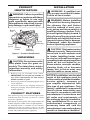
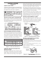
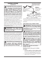
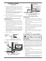
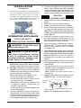
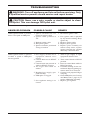
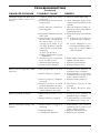
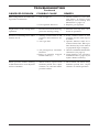
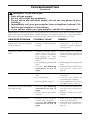
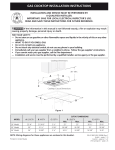
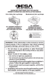
VENTED DECORATIVE GAS LOG HEATER
OWNER’S OPERATION AND INSTALLATION MANUAL
MVO24VNA, MVO24VPA,
MVO18VNA AND MVO18VPA
WARNING: If the information in this manual is not followed exactly, a fire or explosion may result causing
property damage, personal injury or loss of life.
— Do not store or use gasoline or other flammable
vapors and liquids in the vicinity of this or any other
appliance.
— WHAT TO DO IF YOU SMELL GAS
• Do not try to light any appliance.
• Do not touch any electrical switch; do not use any
phone in your building.
• Immediately call your gas supplier from a neighbor’s
phone. Follow the gas supplier’s instructions.
• If you cannot reach your gas supplier, call the fire
department.
— Installation and service must be performed by a qualified installer, service agency or the gas supplier.
Save this manual for future reference.
For more information, visit www.desatech.com
WARNING: Improper installation, adjustment, alteration, service or maintenance can cause injury or property damage. Refer to this manual for correct installation
and operational procedures. For assistance or additional information consult a qualified installer, service
agency or the gas supplier.
WARNING: This appliance is for installation only in
a solid-fuel burning masonry or UL127 factory-built
fireplace, constructed of noncombustible material and
connected to a working flue. (See page 6 for minimum
flue opening.
WARNING: This is a gas-fired heater. It uses air (oxygen) from the room in which it is installed. Provisions
for adequate combustion and ventilation air must be
provided. Refer to the National Fuel Gas Codes, ANSI
Z233.1/NFPA 54, Section 5.3, Air for Combustion and
Ventilation.
This appliance may be installed in an aftermarket,* permanently located, manufactured (mobile) home, where
not prohibited by local codes.
This appliance is only for use with the type of gas indicated on the rating plate. This appliance is not convertible for use with other gases.
* Aftermarket: Completion of sale, not for purpose of resale, from the manufacturer
State of Massachusetts: The installation must be made
by a licensed plumber or gas fitter in the Commonwealth
of Massachusetts.
TABLE OF CONTENTS
Safety Information ............................................... 3
Local Codes ........................................................ 4
Product Identification ........................................... 5
Unpacking ........................................................... 5
Product Features ................................................. 5
Installation ........................................................... 5
Operating Appliance .......................................... 10
Wiring Diagram ...................................................11
Inspecting Burners ............................................ 12
2
Cleaning and Maintenance ................................ 12
Troubleshooting ................................................. 13
Service Hints ..................................................... 17
Technical Service .............................................. 17
Replacement Parts ............................................ 17
Accessories ....................................................... 17
Illustrated Parts Breakdown and Parts List ....... 18
Warranty Information ...........................Back Cover
www.desatech.com
114924-01B
SAFETY INFORMATION
WARNING: This product contains and/or generates chemicals
known to the State of California
to cause cancer or birth defects
or other reproductive harm.
WARNING: Keep flue open
when operating unit.
IMPORTANT: Read this owner’s
manual carefully and completely
before trying to assemble, operate
or service this log set. Improper use
of this log set can cause serious
injury or death from burns, fire,
explosion, electrical shock and
carbon monoxide poisoning.
DANGER: Carbon monoxide
poisoning may lead to death!
Carbon Monoxide Poisoning: Early signs of carbon
monoxide poisoning resemble the flu, with headaches, dizziness or nausea. If you have these signs,
the log set may not be working properly. Get fresh
air at once! Have log set serviced. Some people
are more affected by carbon monoxide than others.
These include pregnant women, people with heart
or lung disease or anemia, those under the influence
of alcohol and those at high altitudes.
Natural & LP Gas: Natural & LP gas are odorless.
An odor-making agent is added to the gas. The
odor helps you detect a gas leak. However, the
odor added to the gas can fade. Gas may be present
even though no odor exists.
Make certain you read and understand all warnings.
Keep this manual for reference. It is your guide to
safe and proper operation of this log set.
WARNING: Do not place log
scraps or lava rocks on burner.
WARNING: Do not use a blower insert, heat exchanger insert or
other accessory not approved for
use with this appliance.
114924-01B
WARNING: Any change to
this log set or its controls can
be dangerous.
WARNING: This appliance
is equipped for (natural or propane/LP) gas. Field conversion
is not permitted.
WARNING: Do not allow fans
to blow directly into the fireplace.
Avoid any drafts that alter burner
flame patterns.
WARNING: Installed decorative glass door enclosures must
be fully opened when operating
this gas appliance.
Due to high temperatures, the
appliance should be located out
of traffic and away from furniture
and draperies.
Do not place clothing or other
flammable material on or near
the appliance. Never place any
objects on the appliance.
Appliance assembly becomes
very hot when running. Keep
children and adults away from hot
surface to avoid burns or clothing
ignition. Appliance will remain hot
for a time after shutdown. Allow
surface to cool before touching.
Carefully supervise young children when they are in the room
with appliance. When using handheld remote accessory, keep selector switch in the OFF position
to prevent children from turning
on burners with remote.
www.desatech.com
3
SAFETY INFORMATION
Continued
You must operate this appliance
with a fireplace screen in place.
Make sure fireplace screen is
closed before running appliance.
Keep the appliance area clear
and free from combustible materials, gasoline and other flammable vapors and liquids.
Children and adults should be
alerted to the hazard of high temperature and should stay away to
avoid burns or clothing ignition.
1. This appliance, as supplied, is only for use
with the type of gas indicated on the rating
plate. This appliance is not convertible for
use with other gases.
2. Do not place propane/LP supply tank(s) inside the structure. Locate propane/LP supply
tank(s) outdoors (propane/LP units only).
3. If you smell gas
• shut off gas supply
• do not try to light any appliance
• do not touch any electrical switch; do not use
any phone in your building
• immediately call your gas supplier from a
neighborʼs phone. Follow the gas supplierʼs
instructions
• if you cannot reach your gas supplier, call
the fire department
4. Never install the log set
• in a recreational vehicle
• where curtains, furniture, clothing or other
flammable objects are less than 42 inches
from the front, top or sides of the log set.
• in high traffic areas
• in windy or drafty areas
5. Before installing in a solid fuel burning fireplace,
the chimney flue and firebox must be cleaned of
soot, creosote, ashes and loose paint by a qualified
chimney cleaner. Creosote will ignite if highly
heated. Inspect chimney flue for damage. If damaged, repair flue before operating appliance.
6. This logset is designed to be smokeless. If logs
ever appear to smoke, turn off appliance and
call a qualified service person. Note: During
initial operation, slight smoking could occur
due to log curing and the burning of manufacturing residues. You may wish to add more
ventilation by opening a window.
4
7. You must operate this log set with fireplace screen
in place and fully closed. Unless provided by
other means, screens shall have openings for
introduction of combustion air.
8. If fireplace has glass doors, never operate with
glass doors closed, If you operate heater with
doors closed, heat buildup inside fireplace will
cause glass to burst. Also if fireplace opening
has vents at the bottom, you must open the
vents before operating heater.
9. To reduce the creation of soot, follow the instructions in Cleaning and Maintenance, page 12.
10. Do not use a blower insert, heat exchanger
insert or other accessory not approved for use
with this log set.
11. The installation and provisions for combustion
and ventilation air must conform with the National Fuel Gas Codes, ANSI Z233.1/NFPA 54,
Section 5.3, Air for combustion and Ventilation.
12. Do not run heater
• where flammable liquids or vapors are used
or stored
• under dusty conditions
13. Do not burn solid fuel in the fireplace after
installing the log set. Do not use this log set
to cook food or burn paper or other objects.
14. Log set becomes very hot when in use. Keep
children and adults away from hot surface to
avoid burns or clothing ignition. Log set will
remain hot for a time after shutdown. Allow
surface to cool before touching.
15. Carefully supervise young children when they
are in the room with the log set.
16. Do not use heater if any part has been exposed
to or under water. Immediately call a qualified
service technician to inspect the room heater
and to replace any part of the control system and
any gas control which has been under water.
17. Turn log set off and let cool before servicing,
installing or repairing. Only a qualified service
person should install, service or repair log set.
18. Provide adequate clearances around air
openings.
LOCAL CODES
Install and use log set with care. Follow all local codes.
In the absence of local codes, use the latest edition of
the National Fuel Gas Code ANSI Z223.1/NFPA 54*
*Available from:
American National Standards Institute, Inc.
1430 Broadway
New York, NY 10018
National Fire Protection Association, Inc.
Battery march park
Quincy, MA 02269
www.desatech.com
114924-01B
PRODUCT
IDENTIFICATION
WARNING: Failure to position
the parts in accordance with these
diagrams or failure to use only
parts specifically approved with
this appliance may result in property damage or personal injury.
Ember
Pod
Piezo
Ignitor
Log Set
Assembly
Control
Knobs
Chassis
Assembly
Figure 1 - Product Identification
UNPACKING
CAUTION: Do not remove the
data plates from the grate assembly. The data plates contain
important warranty and safety
information.
1. Remove log set assembly from carton.
IMPORTANT: Do not pick up assembly by
logs. This could damage the unit. Always
handle assembly by grate.
2. Remove all protective packaging applied to log
set for shipment.
3. Check all items for any shipping damage. If
damaged, promptly inform dealer where you
bought appliance.
PRODUCT FEATURES
This unitized gas log set is tested and approved to
ANSIZ21.60-2003 and CSA 2.2-2003 as a vented
decorative appliance.
This unit has a piezo ignitor. This system requires no
matches, batteries or other sources to light appliance.
An ON/OFF remote is available for use with this
vented log set (see Accessories, page 17). A wall
thermostat or hand-held thermostat remote is not to
be used with vented decorative appliances.
114924-01B
INSTALLATION
WARNING: A qualified service person must install heater.
Follow all local codes.
WARNING: Before installing
in a solid fuel burning fireplace,
the chimney flue and firebox
must be cleaned of soot, creosote, ashes and loose paint by a
qualified chimney cleaner. Creosote will ignite if highly heated. A
dirty chimney flue may create and
distribute soot within the house.
Inspect chimney flue for damage.
If damaged, repair flue damper
before operating appliance.
CAUTION: This heater creates
warm air currents. These currents
move heat to wall surfaces next
to heater. Installing heater next
to vinyl or cloth wall coverings or
operating heater where impurities
(such as, but not limited to, tobacco smoke, aromatic candles,
cleaning fluids, oil or kerosene
lamps, etc.) in the air exist, may
discolor walls or cause odors.
NOTICE: Installation, service and
repair of this appliance must be
performed by a qualified installer,
service agency, company or
gas supplier experienced with
this type of gas appliance. Only
factory authorized components
listed in these instructions may
be used in accordance with the
manufacturer's instructions and
all codes and requirements of
the authority having jurisdiction.
Any modifications to or use of
unauthorized components or
accessory items will void the
manufacturer’s warranty and may
result in a hazardous condition.
www.desatech.com
5
INSTALLATION
Continued
CHECK GAS TYPE
Use the correct gas type (natural or propane/LP) for
your unit. If your gas supply is not correct, do not
instal in fireplace. Call dealer where you bought
the appliance for proper type of appliance.
WARNING: This appliance
is equipped for (natural or propane/LP) gas. Field conversion
is not permitted.
INSTALLATION AND CLEARANCES
Figure 2 shows technical information regarding
the installation of your gas log set. Please make
sure all specifications shown are applicable before
installation is attempted.
SPECIFICATIONS (W.C.)
MANIFOLD
FUEL INLET
PRESSURE
PRESSURE
Observe the smoke and be sure the vent is properly
drawing it up the chimney. If the smoke spills out
into the room, extinguish the flame and remove any
obstruction until proper venting is achieved.
The chimney flue damper must be fixed open to provide a minimum of 32 square inch of free air opening
at all times during operation of the log set. A damper
clamp is included to secure the damper.
The minimum flue sizes shown in Figure 3 are
based on a 6' chimney height using round pipe. Your
minimum flue size will vary based on input rate and
chimney height. Refer to the National Fuel Gas Code
ANSI Z223.1/NFPA 54, Section 6.6 for details.
INSTALLING DAMPER CLAMP
Secure the damper stop clam to the edge of the
damper as shown in Figure 4. If for any reason
this clamp doesn't work on your fireplace, another
suitable clamp or permanent stop must be installed,
or the damper blade must be cut or removed.
Damper
Clamp
Min. Max.
3.5"
10.5"
7"
NG
10"
14"
11"
LP
Figure 2 - Technical Information Chart
Damper
Clamp
Damper
FLUE OPENING SPECIFICATIONS
Note: This vented appliance must be installed only
in a solid-fuel burning or UL127 factory-built fireplace constructed of noncombustible material and
connected to a working flue. The fireplace chimney
must have a permanent vent opening to outside
with minimum openings shown in Figure 3.
LOG SIZING REQUIREMENTS
MINIMUM FIREBOX SIZE
LOG
FRONT REAR* MIN. FLUE
SIZE HEIGHT DEPTH WIDTH WIDTH
SIZE
18"
24"
20"
20"
14"
14"
25"
29"
20.5"
24.5"
6.5"
6.5"
*Measured at 14" depth
Figure 3 - Sizes and Clearances
VENTING SPECIFICATIONS FOR
INSTALLATION
The fireplace chimney flue and vent must be drafting properly. To check the vent for proper drafting:
Light a tightly rolled newspaper on one end and
place it at the inside front edge of the fireplace.
6
Damper
Damper
Masonry
Manufactured
Fireplace
Fireplace
Figure 4 - Attaching Damper Clamp
INSTALLING REMOTE CONTROL
ACCESSORY BRACKET
If installing optional remote control accessory you
will need to install the remote accessory bracket
for the receiver.
Use screws provided to attach bracket to valve
bracket as shown in Figure 5.
Follow installation instructions included with
remote accessory.
Valve Bracket
Remote
Bracket
Figure 5 - Attaching Remote Bracket to
Valve Bracket
www.desatech.com
114924-01B
INSTALLATION
Continued
INSTALLING APPLIANCE
WARNING: Special care is
required if you are installing the
unit into a sunken fireplace. You
must raise the fireplace floor to
allow access to gas log controls.
This will insure adequate air
flow and guard against sooting.
Raise the fireplace floor using
noncombustible material.
CAUTION: Do not pick up appliance assembly by logs. This
could damage unit. Only handle
assembly by grate.
IMPORTANT: Make sure appliance is level. If
unit is not level it will not work properly.
Center the appliance in the fireplace. Make certain
the grate front feet sit inside the front edge of
the fireplace and that there is adequate clearance
around the appliance for access and operation.
Note: The installation of appliances designed for
manufactured home (U.S. only) or mobile home
installation must conform with the standard CAN/
CSA Z240, Mobile Housing, in Canada, or with
the Manufactured Home Construction and Safety
Standard, Title 24 CFR, Part 3280, in the United
States, or when such a standard is not applicable,
ANSI/NCSBCSA225.1/NFPA501A, Manufactured
Home Installations Standard.
CONNECTING TO GAS SUPPLY
WARNING: A qualified service
person must connect heater to gas
supply. Follow all local codes.
WARNING: This appliance
requires a 3/8" NPT (National Pipe
Thread) inlet connection to the
control valve.
CAUTION: Never connect
propane/LP unit directly to the
propane/LP supply. This unit requires an external regulator (not
supplied). Install the external
regulator between the unit and
the propane/LP supply.
WARNING: Never connect natural gas fireplace to private (non-utility) gas wells. This gas is commonly
known as wellhead gas.
Installation Items Needed
Before installing heater, make sure you have the
items listed below.
• approved flexible gas hose and fittings (supplied
with appliance -if allowed by local codes)
• external regulator (propane/LP models only)
• piping (check local codes)
• sealant (resistant to propane/LP gas)
• equipment shutoff valve*
• test gauge connection*
• sediment trap
• tee joint
• pipe wrench
* A CSA design-certified equipment shutoff valve
with 1/8" NPT tap is an acceptable alternative to
test gauge connection. Purchase the optional CSA
design-certified equipment shutoff valve from your
dealer. See Accessories, page 17.
For propane/LP units, the installer must supply
an external regulator. The external regulator will
reduce incoming gas pressure. You must reduce
incoming gas pressure to between 11 and 14 inches
of water. If you do not reduce incoming gas pressure, control valve damage could occur. Install
external regulator with the vent pointing down as
shown in Figure 6. Pointing the vent down protects
it from freezing rain or sleet.
Propane/LP
Supply Tank
External
Regulator
Vent
Pointing
Down
Figure 6 - External Regulator with Vent
Pointing Down
114924-01B
www.desatech.com
7
INSTALLATION
Continued
CAUTION: Use only new, black
iron or steel pipe. Internally-tinned
copper tubing may be used in
certain areas. Check your local
codes. Use pipe of 1/2" diameter
or greater to allow proper gas volume to heater. If pipe is too small,
undue loss of volume will occur.
Installation must include an equipment shutoff
valve, union and plugged 1/8" NPT tap. Locate NPT
tap within reach for test gauge hook up. NPT tap
must be upstream from log set (see Figure 7).
IMPORTANT: Install equipment shutoff valve in an
accessible location. The equipment shutoff valve is for
turning on or shutting off the gas to the appliance.
Apply pipe joint sealant lightly to male NPT
threads. This will prevent excess sealant from
going into pipe. Excess sealant in pipe could result
in clogged heater valves.
WARNING: Use pipe joint
sealant that is resistant to liquid
petroleum (LP) gas.
We recommend that you install a sediment trap in
supply line as shown in Figure 7. Locate sediment
trap where it is within reach for cleaning. Install in
piping system between fuel supply and appliance.
Locate sediment trap where trapped matter is not
likely to freeze. A sediment trap traps moisture and
contaminants. This keeps them from going into
heater controls. If sediment trap is not installed or
is installed wrong, heater may not run properly.
CAUTION: Avoid damage to
gas control. Hold gas control
with wrench when connecting it
to gas piping and/or fittings.
CSA Design-Certified
Equipment Shutoff
Valve with 1/8" NPT
Tap*
Natural
From Gas
Approved Flexible
Meter (5" W.C.**
Gas Hose (If
to 10.5" W.C.
allowed by local
Pressure)
codes)
3" Min.
Propane/LP
Pipe Cap Tee From External
Nipple
Joint Regulator (11"
W.C.** to 14"
Sedament Trap W.C. Pressure)
Figure 7 - Gas Connection
* Purchase the optional CSA design-certified shutoff
valve from your dealer. See Accessories, page 17.
** Minimum inlet pressure for purpose of input
adjustment.
CHECKING GAS CONNECTIONS
WARNING: Test all gas piping
and connections for leaks after
installing or servicing. Correct
all leaks at once.
WARNING: Never use an open
flame to check for a leak. Apply a
noncorrosive leak detection fluid
to all joints. Bubbles forming show
a leak. Correct all leaks at once.
CAUTION: Make sure external regulator has been installed
between propane/LP supply
and appliance. See guidelines
under Connecting to Gas Supply, page 7.
PRESSURE TESTING GAS SUPPLY
PIPING SYSTEM
Test Pressures In Excess Of 1/2 PSIG
(3.5 kPa)
1. Disconnect appliance with its appliance main
gas valve (control valve) and equipment shutoff
valve from gas supply piping system. Pressures
in excess of 1/2 psig will damage control valve.
2. Cap off open end of gas pipe where equipment
shutoff valve was connected.
8
www.desatech.com
114924-01B
INSTALLATION
Equipment
Shutoff Valve
Continued
3. Pressurize supply piping system by either
opening propane/LP supply tank valve for
propane/LP gas or opening main gas valve
located on or near gas meter for natural gas
or using compressed air.
4. Check all joints of gas supply piping system.
Apply noncorrosive leak detection fluid to all
joints. Bubbles forming show a leak.
5. Correct all leaks at once.
6. Reconnect heater and equipment shutoff
valve to gas supply. Check reconnected fittings for leaks.
Test Pressures Equal To or Less Than
1/2 PSIG (3.5 kPa)
1. Close equipment shutoff valve (see Figure 8).
2. Pressurize supply piping system by either
opening propane/LP supply tank valve for
propane/LP gas or opening main gas valve
located on or near gas meter for natural gas
or using compressed air.
3. Check all joints from gas meter to equipment
shutoff valve for natural gas or propane/LP
supply to equipment shutoff valve for propane/
LP (see Figure 9 or 10). Apply noncorrosive
leak detection fluid to all joints. Bubbles forming show a leak.
4. Correct all leaks at once.
Equipment
Shutoff
Valve
Open
Closed
Figure 8 - Equipment Shutoff Valve
Propane/LP
Supply Tank
Equipment
Shutoff Valve
Control Valve
Location
Figure 9 - Checking Gas Joints
(Propane/LP Gas Only)
114924-01B
Gas Meter
Control Valve
Location
Figure 10 - Checking Gas Joints
(Natural Gas Only)
Pressure Testing Appliance Gas
Connections
1. Open equipment shutoff valve (see Figure 8.)
2. Open main gas valve located on or near gas
meter for natural gas or open propane/LP
supply tank valve.
3. Make sure control knob of appliance is in the
OFF position.
4. Check all joints from equipment shutoff valve
to gas control (see Figure 9 or 10). Apply
noncorrosive leak detection fluid to all joints.
Bubbles forming show a leak.
5. Correct all leaks at once.
6. Light appliance (see Operating Appliance,
page 10) Check all other internal joints for
leaks.
7. Turn off appliance.
PLACEMENT OF LOOSE EMBERS
CAUTION: Do not place
any loose embers around pilot
assembly.
Two bags of loose embers are provided with this
unit. For this installation use the embers that are
approximately 1" square in size. If needed, larger
embers can be broken to size. These embers aid
in concealing the burner pan, directing flames
through the ember bed, quiet operation of the
unit and gives a natural random flame pattern (see
Figure 11, page 10).
Place embers as follows:
1. Place embers around the center ember bed or
ember pod.
2. Place individual embers on their edge (not flat)
along the top of the burner pan. This aids in
directing flames from the burner through the
ember bed.
Note: Too many embers or embers placed flat
along burner pan can suppress the flames.
www.desatech.com
9
INSTALLATION
Continued
3. When unit is lit, check flames for random appearance and ember bed glowing red-orange in color
(see Burner Flame Pattern, page 12). If this is
not happening, either add, remove or reposition
loose embers. IMPORTANT: Turn unit off and
let cool before repositioning loose embers.
Figure 11 - Placement of Embers
OPERATING APPLIANCE
FOR YOUR SAFETY
READ BEFORE LIGHTING
WARNING: Keep flue open
when operating unit.
WARNING: If you do not follow these instructions exactly,
a fire or explosion may result
causing property damage, personal injury or loss of life.
A. This appliance has a pilot which must be
lighted with a piezo ignitor. When lightning
the pilot, follow these instructions exactly.
B. BEFORE LIGHTING smell all around the
appliance area for gas. Be sure to smell next
to the floor because some gas is heavier than
air and will settle on the floor.
WHAT TO DO IF YOU SMELL GAS
• Do not try to light any appliance.
• Do not touch any electric switch; do not
use any phone in your building.
• Immediately call your gas supplier from
a neighborʼs phone. Follow the gas
supplierʼs instructions.
• If you cannot reach your gas supplier, call
the fire department.
C. Use only your hand to push in or turn gas
control knob. Never use tools. If the knob
will not push in or turn by hand, do not try
to repair it, call a qualified technician. Force
or attempted repair may result in a fire.
10
D. Do not use this appliance if any part has been
under water. Immediately call a qualified
service technician to inspect the appliance and
to replace any part of the control system and
any gas control which has been under water.
LIGHTING
INSTRUCTIONS
1. STOP! Read the safety information, column 1.
2. Make sure switch is in OFF position.
3. Be sure gas line shut-off valve is OPEN.
4. Press in and turn control knob clockwise
to the OFF position (see Figure 12).
Note: Knob cannot be turned from PILOT
to OFF unless knob is pushed in slightly. DO
NOT FORCE.
5. Wait five (5) minutes to clear out any gas.
If you then smell gas, STOP! Follow "B" in
the safety information in column 1. If you
don't smell gas, go on the next step.
6. Press in and turn control knob counterto the PILOT position.
clockwise
Press in control knob for five (5) seconds
(see Figure 12).
7. With control knob pressed in, press and release
ignitor button. This will light pilot. If needed,
keep pressing ignitor button until pilot lights.
Note: If pilot does not stay lit, contact a
qualified service person or gas supplier for
repairs.
8. Keep control knob pressed in for 30 seconds
after lighting pilot. After 30 seconds, release
control knob.
• If control knob does not pop out when
released, contact a qualified service person
or gas supplier for repairs.
Note: If pilot goes out, repeat steps 4
through 8.
9. Slightly push in and turn control knob counterclockwise
to the ON position.
Control
Knob
Piezo Ignitor Flame Adjustment Knob
Figure 12 - Setting Control Knobs
www.desatech.com
114924-01B
OPERATING APPLIANCE
Continued
10. Wait one minute and move switch to the
ON position to light burner. Note: AUTO is
only functional when using optional remote
control accessory.
11. Set flame adjustment knob to any level
between HI and LO.
TO TURN OFF GAS
TO APPLIANCE
1. Push switch into OFF position. The pilot
will remain lit for normal service.
2. Access control knobs.
3. Depress gas control knob slightly and turn
clockwise to OFF. Do not force.
IMPORTANT: Do not leave the selector switch
in the REMOTE or ON position when the pilot
is not lit. This will drain the battery.
ON/OFF SERIES (MODEL GHRCB)
Hold the control button on the hand-held remote
until burner turns on. Hold the control button
again until burner turns off (see Figure 14).
To Lock press both buttons on hand-held
remote control until light stops flashing. Handheld remote control is now locked. If the fire is
on it will be turned off automatically. In the
locked state, the light will not light up when
any button is pressed.
To Unlock press both buttons together on handheld remote control until the light stops flashing.
The hand-held remote is now unlocked.
OPTIONAL HAND-HELD
REMOTE OPERATION
Control Button
Turns Burner
On and Off
Note: Remote control accessory must be purchased separately (see Accessories, page 17).
Follow instructions included with the remote
control.
NOTICE: You must light the pilot
before using the hand-held remote control unit. See Lighting
Instructions on page 10.
After lighting, let pilot flame burn for about
one minute. Turn control knob to ON position. Adjust flame adjustment knob anywhere
between HI and LO. Flip AUTO/OFF/ON
switch to AUTO. Slide the selector switch
to the REMOTE position (see Figure 13).
Note: The burner may light if hand-held
remote was on when selector switch was last
turned off. You can now turn the burner on and
off with the hand-held remote control unit.
Figure 14 - On/Off Hand-Held Remote
Control Unit (GHRCB)
WIRING DIAGRAM
When Using Remote
To Remote
Receiver
Thermopile
Control Knob
REMOTE
OFF
ON
Piezo
Ignitor
Selector Switch in
Flame
REMOTE Position
Adjustment
Knob
Figure 13 - Setting the Selector Switch,
Control Knob and Flame Adjustment
Knob for Remote Operation
114924-01B
www.desatech.com
11
INSPECTING BURNERS
Check pilot flame pattern and burner flame patterns often.
PILOT FLAME PATTERN
You can view the pilot light through the pilot viewing hole on the pilot bracket. This is located under
the front grate bar on the right side of the log set.
Figure 15 shows a correct pilot flame pattern.
Figure 16 shows an incorrect pilot flame pattern.
The incorrect pilot flame is not touching the thermocouple. This will cause the thermocouple to
cool. When the thermocouple cools, the appliance
will shut down.
If pilot flame pattern is incorrect, as shown in
Figure 16
• turn appliance off (see To Turn Off Gas to
Appliance, page 11)
• see Troubleshooting, page 13
Note: The pilot flame on natural gas units will
have a slight curve but flames should be blue and
have no yellow or orange color.
Thermocouple
Figure 15 - Correct Pilot Flame Pattern
(Your pilot may vary from pilots shown)
Thermocouple
Figure 16 - Incorrect Pilot Flame Pattern
(Your pilot may vary from pilots shown)
BURNER FLAME PATTERN
Figure 17 shows correct burner flame pattern.
NOTICE: Do not mistake orange
flames with yellow tipping. Dirt
or other fine particles are burned
by appliance, causing brief
patches of orange flame.
Yellow Flames
with Orange
Streaks
Figure 17 - Correct Burner Flame Pattern
12
If burner flame pattern is incorrect, as shown in
Figure 18.
• turn appliance off (see To Turn Off Gas to Appliance, page 10)
• see Troubleshooting, page 13
Dark Orange
Flames
Figure 18 - Incorrect Burner Flame
Pattern
CLEANING AND
MAINTENANCE
WARNING: Turn off the appliance and allow to cool before
cleaning.
CAUTION: You must keep
control areas, burners and circulating air passageways of fireplace clean. Inspect these areas
of fireplace before each use. Have
fireplace and chimney (if applicable) inspected yearly by a qualified service person. Fireplace may
need more frequent cleaning due
to excessive lint from carpeting,
bedding material, etc.
Only limited cleaning will be required under normal use of this appliance. Dust the front grate and
top of receiver/valve. Do not use cleaning fluids to
clean logs or any other part of the appliance.
If, after a period of use, the flames start to exhibit
unusual shapes and behavior or the burner fails to
ignite smoothly, then the burner holes may require
some cleaning. If this happens, we recommend
that you contact your nearest authorized service
technician to get the appliance serviced.
• Keep area around log set clean and clear of debris.
• Periodically inspect the air mixer and burner
tube for foreign matter blocking the air inlet
and flame holes.
• Once every year a qualified agency or certified
chimney sweep should examine and clean the
venting system of the fireplace.
www.desatech.com
114924-01B
TROUBLESHOOTING
WARNING: Turn off appliance and let cool before servicing. Only
a qualified service person should service and repair heater.
CAUTION: Never use a wire, needle or similar object to clean
ODS/pilot. This can damage ODS pilot unit.
Note: All troubleshooting items are listed in order of operation.
OBSERVED PROBLEM
POSSIBLE CAUSE
REMEDY
When ignitor button is pressed,
there is no spark at ODS/pilot
1. Ignitor electrode not connected to ignitor cable
2. Ignitor cable pinched or
wet
1. Reconnect ignitor cable
3. Broken ignitor cable
4. Bad piezo ignitor
5. Ignitor electrode positioned
wrong or broken
When ignitor button is pressed
in there is spark at ODS/pilot
but no ignition
1. Gas supply turned off or
equipment shutoff valve
closed
2. Control knob not in PILOT
position
3. Control knob not pressed in
while in PILOT position
4. Air in gas lines when installed
5. Depleted gas supply (propane/LP only)
6. ODS/pilot is clogged
7. Gas regulator setting is incorrect
114924-01B
www.desatech.com
2. Free ignitor cable if pinched
by any metal or tubing. Keep
ignitor dry
3. Replace ignitor cable
4. Replace piezo ignitor
5. Replace pilot assembly for
remote-ready units; replace
ignitor electrode for variable
manually controlled units
1. Turn on gas supply or open
equipment shutoff valve
2. Turn control knob to PILOT
position
3. Press in control knob while in
PILOT position
4. Continue holding down control knob. Repeat igniting operation until air is removed
5. Contact local propane/LP gas
company
6. Clean ODS/pilot (see Cleaning
and Maintenance, page 12) or
replace ODS/pilot assembly
7. Replace gas regulator
13
TROUBLESHOOTING
Continued
OBSERVED PROBLEM
POSSIBLE CAUSE
REMEDY
ODS/pilot lights but flame goes
out when control knob is released
1. Control knob not fully
pressed in
2. Control knob not pressed in
long enough
1. Press in control knob fully
3. Safety interlock system has
been triggered
4. Equipment shutoff valve not
fully open
5. Pilot flame not touching
thermocouple, which allows
thermocouple to cool,
causing pilot flame to go
out. This problem could be
caused by one or both of the
following:
A) Low gas pressure
B) Dirty or partially clogged
ODS/Pilot
6. Thermocouple connection
loose at control valve
7. Thermocouple damaged
8. Control valve damaged
Burner does not light after ODS/
pilot is lit
1. Inlet gas pressure is too low
2. Burner orifice(s) clogged
3. Burner orifice(s) diameter
too small
4. Remote selector in OFF
position (Remote use only)
5. Wire disconnected from gas
control (Remote use only)
2. After ODS/pilot lights, keep
control knob pressed in for 30
seconds
3. Wait one minute for safety interlock system to reset. Repeat
ignition operation
4. Fully open equipment shutoff
valve
5. A) Contact local natural or
propane/LP gas company
B) Clean ODS/pilot (see
Cleaning and Maintenance,
page 12) or replace ODS/
pilot assembly
6. Hand tighten until snug, then
tighten 1/4 turn more
7. Replace pilot assembly
8. Replace control valve
1. Contact local natural or
propane/LP gas company
2. Clean burner(s) (see Cleaning
and Maintenance, page 12) or
replace burner orifice(s)
3. Replace burner orifice(s)
4. Put remote selector in ON
position
5. See Wiring Diagram, page
11)
Delayed ignition of burner
1. Manifold pressure is too
low
2. Burner orifice(s) clogged
1. Contact local natural or
propane/LP gas company
2. Clean burner(s) (see Cleaning
and Maintenance, page 12)
Burner backfiring during combustion
1. Burner orifice is clogged or
damaged
1. Clean burner (see Cleaning
and Maintenance, page 12) or
replace burner orifice
2. Replace damaged burner
3. Replace gas regulator
2. Damaged burner
3. Gas regulator defective
14
www.desatech.com
114924-01B
TROUBLESHOOTING
Continued
OBSERVED PROBLEM
POSSIBLE CAUSE
REMEDY
Dark orange flame in burner during burner combustion
1. Not enough air
2. Gas regulator defective
1. Check burner(s) for dirt
and debris. If found, clean
burner(s) (see Cleaning and
Maintenance, page 12)
2. Replace gas regulator
Slight smoke or odor during initial
operation
1. Residues from manufacturing
processes and log curing
1. Problem will stop after a few
hours of operation
Produces a whistling noise when
burners are lit
1. Turning control knob to HI
position when burners are
cold
2. Air is gas line
1. Turn control knob to LO
position and let warm up for
a minute
2. Operate burners until air is
removed from line. Have gas
line checked by local natural
or propane/LP gas company.
3. Observe minimum installation
clearances (see page 6)
4. Clean burners (see Cleaning
and Maintenance, page 12) or
replace burner orifice(s)
3. Air passageways on heater
blocked
4. Dirty or partially clogged
burner orifice(s)
White powder residue forming
within burner box or on adjacent
walls or furniture
114924-01B
1. When heated, vapors from
furniture polish, wax, carpet
cleaners, etc, turn into white
powder residue
www.desatech.com
1. Heat turned off when using
furniture polish, wax, carpet
cleaners or similar products
15
TROUBLESHOOTING
Continued
WARNING: If you smell gas
• Shut off gas supply.
• Do not try to light any appliance.
• Do not touch any electrical switch; do not use any phone in your
building.
• Immediately call your gas supplier from a neighbor’s phone. Follow the gas supplier’s instructions.
• If you cannot reach your gas supplier, call the fire department.
IMPORTANT: Operating appliance where impurities in air exist may create odors. Cleaning supplies,
paint, paint remover, cigarette smoke, cements and glues, new carpet or textiles, etc., create fumes. These
fumes may mix with combustion air and create odors. These odors will disappear over time.
OBSERVED PROBLEM
POSSIBLE CAUSE
REMEDY
Appliance produces a clicking/
ticking noise just after burners
are lit or shut off
1. Metal expanding while
heating or contracting while
cooling
1. This is common with most
appliances. If noise is
excessive, contact qualified
service person
Appliance produces unwanted
odors
1. Appliance burning vapors
from paint, hair spray,
glues, cleaners, chemicals,
new carpet, etc. (See
IMPORTANT statement
above)
2. Low fuel supply (propane/LP
only)
3. Gas leak. See Warning
statement at top of
page
1. Open window to ventilate
room. Stop using odor causing
products while appliance is
running
1. Not enough fresh air is available
2. Low line pressure
1. Open window and/or door for
ventilation
2. Contact local natural or
propane/LP gas company
3. Clean ODS/pilot (see Cleaning
and Maintenance, page 12)
Appliance shuts off in use
3. Pilot is partially clogged
2. Refill supply tank (propane/LP
only)
3. Locate and correct all leaks (see
Checking Gas Connections,
page 8)
Gas odor even when control knob
is in OFF position
1. Gas leak. See Warning
statement at top of
page
2. Control valve or gas control
defective
1. Locate and correct all leaks (see
Checking Gas Connections,
page 8)
2. Replace control valve or gas
control
Gas odor during combustion
1. Foreign matter between
control valve and burner
2. Gas leak. See Warning
statement at top of
page
1. Take apart gas tubing and
remove foreign matter
2. Locate and correct all leaks (see
Checking Gas Connections,
page 8)
16
www.desatech.com
114924-01B
SERVICE HINTS
ACCESSORIES
When Gas Pressure is Too Low
• pilot will not stay lit
• burners will have delayed ignition
• propane/LP gas supply may be low
You may feel your gas pressure is too low. If
so, contact your local propane/LP or natural gas
supplier.
Purchase these appliances from your local dealer.
If they can not supply these accessories, call DESA
at 1-866-672-6040 for referral information. You
can also write to the address listed on the back
page of this manual.
TECHNICAL SERVICE
You may have further questions about installation,
operation or troubleshooting. If so, contact DESAʼs
Technical Service Department at 1-866-672-6040.
When calling please have your model and serial
numbers of your heater ready.
You can also visit DESAʼs technical services web
site at www.desatech.com.
EQUIPMENT SHUTOFF VALVE
GA5010
Equipment shutoff valve with 1/8" NPT tap. Fits
1/2" pipe.
REPLACEMENT PARTS
Note: Use only original replacement parts. This
will protect your warranty coverage for parts
replaced under warranty.
PARTS UNDER WARRANTY
Contact authorized dealers of this product. If they
canʼt supply original replacement part(s), call DESAʼs
Technical Service Department at 1-866-672-6040.
When calling DESA, have ready
• your name and address
• model and serial numbers of your log set
• how log set was malfunctioning
• type of gas used (propane/LP or natural gas)
• purchase date
Usually, we will ask you to return the part to the
factory.
PARTS NOT UNDER WARRANTY
Contact authorized dealers of this product. If they
canʼt supply original replacement part(s), call
DESA at 1-866-672-6040 for referral information.
When calling DESA, have ready
• model number of your log set
• the replacement part number
FIREPLACE HOOD
Black - GA6050
Brass - GA6052
Antique Brass - GA6053
Helps deflect heat away from mantel or wall above
fireplace. Fits opening 28" to 48" wide.
DAMPER CLAMP - GA6080
(Not Shown)
Permanently opens chimney flue damper for
vented operation.
LAVA ROCK - GA6060
(Not Shown)
Order when additional rock is desired (1.8 lb. bag)
RECEIVER AND HAND-HELD
REMOTE CONTROL KIT - GHRCB
Allows the gas log heater to be turned on and off
using a hand-held remote control.
CLEANING KIT - GCK
(Not Shown)
Your vented gas appliance requires regular cleaning
and maintenance to prevent performance problems.
This kit gives you the tools and instructions to make
it easy to clean all critical areas of your appliance.
114924-01B
www.desatech.com
17
ILLUSTRATED PARTS BREAKDOWN
MVO24VNA, MVO24VPA
MVO18VNA, MVO18VPA
17
16
15
7
1
9
8
6
13
5
10
3
4
18
14
12
2
11
www.desatech.com
114924-01B
PARTS LIST
This list contains replaceable parts used in your heater. When ordering parts, follow the instructions
listed under Replacement Parts on page 17 of this manual.
KEY
NO. MVO24VNA
PART NUMBER
MVO24VPA MVO18VNA
MVO18VPA
DESCRIPTION
1
2
3
4
5
6
7
8
9
10
11
12
13
14
15
16
17
111793-01
111817-02
099998-01
103784-02
103784-01
097159-04
114942-01
111796-01
111807-01
112376-01
111828-01
114930-02
26205
114936-01
**
114933-02
**
111793-01
111817-02
099998-01
103784-02
103784-01
097159-04
114942-01
111796-01
111807-02
103778-01
111818-01
114930-02
23109
114936-01
**
114933-02
**
111808-02
111817-02
099998-01
103784-02
103784-01
097159-04
114942-01
111796-01
111807-02
103778-01
111828-01
114930-01
23109
114936-02
**
114933-01
**
Grate
Flexible Tube
Fan Switch
Knob Extension (HI/LOW)
Knob Extension (ON/OFF)
Piezo Ignitor
Heat Shield
Valve Bracket
Valve
Pilot Assembly
Brass Fitting
Pilot Bracket
Gas Orifice
Ventury
Burner
Plate Burner
Log Set
100563-01
103877-01
100639-01
111228-02
114928-11
GA6060
115597-01
112799-01
901242-01
100563-01
103877-01
100639-01
111228-02
114928-12
GA6060
115597-01
112799-01
901242-01
111808-02
111817-02
099998-01
103784-02
103784-01
097159-04
114942-01
111796-01
111807-01
112376-01
111828-01
114930-01
26205
114936-02
**
114933-01
**
QTY.
1
1
1
1
1
1
1
1
1
1
2
1
1
1
1
1
1
PARTS AVAILABLE NOT SHOWN
100563-01
103877-01
100639-01
111228-02
114928-09
GA6060
115597-01
112779-01
901242-01
100563-01
103877-01
100639-01
111228-02
114928-10
GA6060
115597-01
112799-01
901-242-01
Warning Plate
Lighting Instruction
Caution Decal
1/8" Flex Gas Line
Rating Plate
Lava Rock
Log Repair Kit
Ember Flakes Kit
Damper Clamp
1
1
1
1
1
1
1
1
1
** Not a field replaceable part.
114924-01B
www.desatech.com
19
WARRANTY INFORMATION
KEEP THIS WARRANTY
Model
Serial No.
Date Purchased
Always specify model and serial numbers when communicating with the factory.
We reserve the right to amend these specifications at any time without notice. The only warranty applicable is our
standard written warranty. We make no other warranty, expressed or implied.
LIMITED WARRANTY
VENTED GAS LOG APPLIANCES
DESA warrants this product to be free from defects in materials and components for four (4) years from the date
of first purchase, provided that the product has been properly installed, operated and maintained in accordance
with all applicable instructions. To make a claim under this warranty the Bill of Sale or cancelled check must be
presented.
This warranty is extended only to the original retail purchaser. This warranty covers the cost of part(s) required to
restore this heater to proper operating condition and an allowance for labor when provided by a DESA Authorized
Service Center. Warranty part(s) MUST be obtained through authorized dealers of this product and/or DESA who
will provide original factory replacement parts. Failure to use original factory replacement parts voids this warranty. The heater MUST be installed by a qualified installer in accordance with all local codes and instructions
furnished with the unit.
This warranty does not apply to parts that are not in original condition because of normal wear and tear or parts that
fail or become damaged as a result of misuse, accidents, lack of proper maintenance or defects caused by improper
installation. Travel, diagnostic cost, labor, transportation and any and all such other costs related to repairing a
defective heater will be the responsibility of the owner.
TO THE FULL EXTENT ALLOWED BY THE LAW OF THE JURISDICTION THAT GOVERNS THE SALE
OF THE PRODUCT; THIS EXPRESS WARRANTY EXCLUDES ANY AND ALL OTHER EXPRESSED
WARRANTIES AND LIMITS THE DURATION OF ANY AND ALL IMPLIED WARRANTIES, INCLUDING
WARRANTIES OF MERCHANTABILITY AND FITNESS FOR A PARTICULAR PURPOSE TO FOUR (4)
YEARS ON ALL COMPONENTS FROM THE DATE OF FIRST PURCHASE; AND DESAʼS LIABILITY IS
HEREBY LIMITED TO THE PURCHASE PRICE OF THE PRODUCT AND DESA SHALL NOT BE LIABLE
FOR ANY OTHER DAMAGES WHATSOEVER INCLUDING INDIRECT, INCIDENTAL OR CONSEQUENTIAL DAMAGES.
Some states do not allow a limitation on how long an implied warranty lasts or an exclusion or limitation of
incidental or consequential damages, so the above limitation on implied warranties or exclusion or limitation on
damages may not apply to you.
This warranty gives you specific legal rights and you may also have other rights that vary from state to state.
For information about this warranty write:
2701 Industrial Drive
P.O. Box 90004
Bowling Green, KY 42102-9004
www.desatech.com
114924 01
NOT A UPC
114924-01
Rev. B
01/05