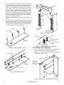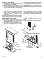
1
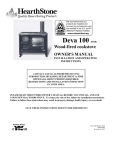
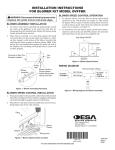
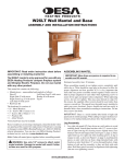
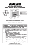
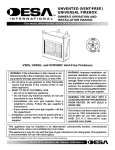
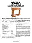
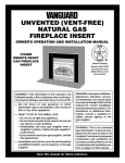
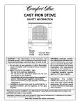
W36AUA and GMC55FA Wall Mantel and
Base with Perimeter Trim
ASSEMBLY AND INSTALLATION INSTRUCTIONS
ox
Fireb er
et
m
Peri
ded
c
n
I lu
Trim
This
With
el
Mant
Important: Read entire instruction sheet before
assembling or installing mantel kit.
These mantels are only approved for use with any
DESA Heating Products 36" fireplace system. Do
not use mantel with any other product.
This mantel kit contains the following:
• Mantel pieces - unassembled and marked as follows:
#1 Base
#2 Right Side with arrow
#3 Right Front Leg with arrow
#4 Left Side with arrow
#5 Left Front Leg with arrow
#6 Header with arrow
#7 Top
#8 Header Assembly Blocks (2)
• Perimeter Trim Kit (for Gas Fireplace)
PT36
• Hardware Kit*
16 - Metal Brackets
118937-01
32 - Screws M6 x 12 mm (1/2")
121149-01
14 - Screws M6 x 30 mm (1 1/4")
121335-01
14 - Washers M6
121336-01
1 - Allen Wrench
121337-01
* Extra hardware may be included.
If any wood pieces are missing or damaged, contact the
dealer where you purchased this mantel for replacement.
If hardware or trim is missing or damaged, contact DESA
Heating Products at 1-866-672-6040 for referral. You can
also visit DESA Heating Products' technical service web site
at www.desatech.com.
WARNING: Follow guidelines of paint or finish
manufacturer. Use care when finishing or painting an
unfinished mantel (W36AUA only). Do not finish or paint
mantel pieces near running heater or open flame. These
vapors are highly flammable.
IMPORTANT: If you are staining an unfinished mantel (W36AUA
only), remove any sawdust, dirt or oils. This will prevent blemishes from appearing under the stain. Stain mantel before
assembling according to manufacturer’s instructions. Apply
sanding sealer.
IMPORTANT: If you are painting an unfinished mantel
(W36AUA only), assemble mantel before painting. Follow
directions listed on paint for wood products. Apply base coat
and top coat following directions listed on product.
Note: Gather all mantel pieces together before assembling.
Assembling Mantel
WARNING: Use only 1/2" screws to attach metal
angle brackets. Damage to mantel will result if other
screws are used for this purpose.
IMPORTANT: More than one person is required to lift
assembled mantel. Lift mantel by leg assemblies. Lifting
by header or mantel top could damage mantel.
When assembling mantel do not tighten screws completely
until told to do so. There should be some play in the pieces
to allow for proper alignment and best possible fit. It is very
important that more than one person assemble mantel. Panels
must be held in proper alignment to each other while tightening
screws to assure fewer gaps and proper surface alignment.
When tightening screws, do not over tighten. This may cause
threads to strip. The supplied Allen wrench should be used
rather than a power screwdriver. Panels have threaded inserts
installed at screw locations. Screws should start and turn easily
in threaded holes when assembled according to instructions.
Do not force screws into holes.
IMPORTANT: There is a serial number label inside of right
side panel and on outside package. When calling to request
technical assistance or for replacement parts please have
that number ready.
www.desatech.com
1. Lay right side panel (#2) face down on a soft surface
to avoid marking finish. Attach four brackets with 1/2"
screws to bottom of right front leg (#3) leaving screws
slightly loose. Face brackets out (see Figure 1, page 2).
Place right front leg (#3) over right side (#2) as shown
in Figure 2, page 2, paying close attention to up arrows
on panels. Align threaded holes with brackets on side.
Start four 1/2" screws through brackets. Align bottom of
side and leg assembly so they are flush with each other.
Hold these pieces securely in alignment while tightening
(but not over tightening) screws.
2. Assemble left side (#4) and left leg (#5) as described in
step 1.
3. You may prefer to lay mantel face down on a soft surface
instead of upright to position header. Position header (#6)
between leg assemblies with direction arrow pointing up
(see Figure 3). Attach header assembly blocks (#8) with
1 1/4" screws and washers (see Figure 4).
Header
Shoulder
Left Leg
Assembly
Brackets
1/2" Screws
Right Leg
Assembly
Figure 3 - Installing Header
Leg
Assembly
1 1/4" Screw
Washer
Header Assembly
Block #8
Header
Right Side
Figure 4 - Attaching Header to Leg Assembly
Attaching top of mantel
Figure 1 - Attaching Brackets to Side
1. Place mantel top (#7) onto upright leg assembly (see
Figure 5). Align back of top with back of sides.
2. Using six 1 1⁄4" screws with washers, attach top to header/
leg assembly (see Figure 5).
Right Front Leg
Top
1
Washer 1 /4" Screw
Right Side
Back of Top
Flush with
Back of Leg
Assembly
1/2" Screws
Figure 2 - Attaching Front Leg
Leg
Assemblies
Figure 5 - Attaching Top to Leg and Header Assembly
www.desatech.com
121559-01A
Fireplace Installation
1. Fireplace should be fully assembled. See Assembling
Fireplace in fireplace owner’s manual.
2. Place mantel base close to installation location. See fireplace owner’s manual for installation clearances. Leave
enough room to get behind mantel once fireplace and
mantel assembly have been attached to base if installing
a fireplace with flange.
3. If installing gas fireplace, install gas line. See Connecting
to Gas Supply in fireplace owner’s manual. Remember
to leave access to the gas shutoff valve somewhere on
the base or where it is accessible to the user. Check
for leaks. See Checking Gas Connections in fireplace
owner’s manual.
IMPORTANT: If your fireplace has a nailing flange see Installing
Fireplace with Flange. If your fireplace does not have a nailing
flange see Installing Fireplace without Flange, page 4.
Installing Fireplace with Flange
1. Position fireplace on base centering left to right. Carefully position gas lines. IMPORTANT: Use caution when
positioning fireplace on base as base may scratch.
2. With assistance, carefully place mantel over fireplace
(see Figure 6). Fireplace nailing flanges will be to inside
of mantel. Align mantel over threaded holes in base. Make
sure back of mantel is flush with back of mantel base.
Adjust fireplace as necessary.
3. Attach mantel to base using 8 brackets and 1/2" screws,
4 per leg assembly into threaded holes in base and leg
assembly (see Figure 7).
4. Adjust fireplace so that it fits into mantel opening properly.
5. Gas fireplace with louver door: Lower bottom louver door.
Use two screws provided in fireplace hardware package
and attach fireplace to wooden base (see Figure 8). Close
louver door.
Gas fireplace with fixed louver: Before installing logs or
burner assembly (see owner’s manual) remove screws
securing floor to assembly. Lift floor for access to bottom of fireplace. Use two screws provided in fireplace
hardware package and attach fireplace base to wooden
base (see Figure 9, page 4). Reinstall floor with screws
removed previously.
7. If using perimeter trim that came with your mantel and
it has not yet been assembled, see Assembling Perimeter Trim, page 4. Place metal trim on shoulder screws
on fireplace. Firmly snap trim assembly over shoulder
screws.
8. Carefully push mantel and base into position against wall.
Bracket with 1/2"
Screws
Figure 7 - Attaching Mantel Assembly to Mantel Base
H
I
Shoulder
Screw
Bottom
Louver Door
F
F
O
O
N
L
O
P
IL OT
Shoulder
Screw
Gas Line
Access Hole
Possible
Shutoff Valve
Locations
Hole for Attaching
Fireplace System to
Wooden Mantel Base
Figure 8 - Attaching Fireplace to Mantel and Mantel Base
Mantel
Base
Figure 6 - Installing Fireplace with Flange
121559-01A
www.desatech.com
Screws
Fixed
Louver
Holes are Behind Louver on
Fireplace Bottom for Attaching
Fireplace to Wooden Mantel
Base.
Shoulder
Screw
Figure 9 - Screw Locations for Fireplaces with Fixed Louver
Installing Fireplace without Flange
1. Place mantel assembly on wood base and center left to
right having back of assembly flush with back of base.
2. Attach mantel to base using 6 brackets and 1/2" screws,
3 per leg assembly into threaded holes in base and leg
assembly (see Figure 7, page 3).
3. Position fireplace inside mantel (see Figure 10). Carefully position gas lines. Important: Use caution when
positioning fireplace on base. Base may scratch easily.
4. Gas fireplace with louver door: Lower bottom louver
door. Use two screws provided in fireplace hardware
package and attach fireplace to wooden base (see Figure
8, page 3). Close louver door
Gas fireplace with fixed louver: Before installing logs or
burner assembly (see owner’s manual) remove screws
securing floor to assembly. Lift floor for access to bottom of fireplace. Use two screws provided in fireplace
hardware package and attach fireplace base to wooden
base (see Figure 9). Reinstall floor with screws removed
previously.
5. Assemble perimeter trim, see Assembling Perimeter
Trim. Firmly snap trim assembly over shoulder screws
on fireplace.
6. Carefully push mantel and base into position against
wall.
Shoulder
Screw
Mantel
Base
Figure 10 - Installing Fireplace without Flange
Assembling Perimeter Trim (Gas
Fireplace Only)
1. Remove packaging from three pieces of metal trim.
2. Locate two adjusting plates with set screws, and two
shims in the hardware packet.
3. Align shim under adjusting plate as shown in Figure 11.
4. Slide one end of adjusting plate/shim in slot on mitered
edge of top trim (see Figure 11).
5. Slide other end of adjusting plate/shim in slot on mitered
edge of side trim (see Figure 11).
6. While firmly holding edges of trim together, tighten both
set screws on the adjusting plate with slotted screwdriver.
7. Repeat steps 2 through 6 for other corner.
Set Screws
Top Trim
Adjusting
Plate
2701 Industrial Drive
P.O. Box 90004
Bowling Green, KY 42102-9004
1-866-672-6040
Slot
Mitered Edge
Side Trim
Shim
Slot
Figure 11 - Assembling Metal Trim
121559 01
NOT A UPC
121559-01
Rev. A
04/07