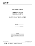
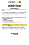
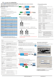
1
PORTABLE GASOLINE
GENERATORS
F
F
U
E
L
SUPPLEMENTAL INSTRUCTIONS FOR FACTORY INSTALLED
AUTO-IDLE EQUIPPED GENERATORS
12
0 VO
LT
S
RE
SE
TE T
ST
Au
to-
ON
Idl
e
OF
00
HO
EN
M
00
00
UR
S
05
1/1
0
F
RE
SE
T
24
0 VO
LT
S
RE
SE
T
10,000 Watt Portable Generators
(See Owner's Manual and Installation Manual for General Operation)
IMPORTANT
Read and understand this manual before operating or servicing
generator. Improper use of generator can cause serious injury.
Keep this manual for future reference.
Notice: The 250 volt/50 amp receptacle is not connected through the
auto-idle circuit. Auto-idle rocker switch must be turned off to get
full power out of this receptacle (see Figure 1).
STOPPING ENGINE
IMPORTANT: The loaded engine speed is preset. The throttle is
locked in preset position. Do not adjust throttle.
WARNING: Improper installation, adjustment, alteration, service, or maintenance can cause injury or
property damage. Only a qualified electrical service
person should service and repair generator.
Follow the steps below to stop engine.
1. Remove all electrical loads from generator (see Disconnecting
Electrical Loads in owner’s manual, page 13). Remove electrical loads one at a time.
2. Let engine run for two or three minutes after removing electrical loads. This lets engine cool slightly.
3. Turn engine key switch to the OFF position (see Figure 1).
4. Turn fuel valve off. Do this by rotating valve, located under
fuel tank, clockwise to the horizontal position (see Figure 3).
• Generator produces high voltage. Use extreme
caution when working on electrical parts.
• Turn off generator and let cool before installation.
Severe burns may result.
• Remove spark plug wire from spark plug before
installation. This will prevent accidental starting.
• Use only factory-approved replacement parts.
S
PRESTART
RE
SE
TE T
ST
Operate generator on a firm, dry, and clean surface. The surface must
be level. Protect generator from heavy dust, sand, dirt, rain, or snow.
Do not locate generator near standing water and snow. Make sure
area is well-vented.
Au
ON
to-I
dle
OF
EN
00 M
00
00
HO
0
U
RS
F
5
RE
SE
T
1/1
0
WARNING: Only responsible adults should use
generator. Never let anyone operate generator without proper instructions.
Auto-Idle Switch
(Rocker Switch)
RE
SE
T
24
0V
OL
TS
RE
SE
T
RE
SE
T
Note: If oil level is too low, oil alert system will keep engine from
starting (see Oil Alert System in owner’s manual, page 8). Make sure
oil level is full before starting. See Engine Oil in owner’s manual,
page 8.
250 volt/50 amp
receptacle
Figure 1 - Auto-Idle Switch Location
Before starting the engine, disconnect all electric loads from generator.
STARTING
IMPORTANT: The loaded engine speed is preset. The throttle is
locked in preset position. Do not adjust throttle. Preset position lets
engine run at 3600 RPM under load. The engine must maintain 3600
RPM for generator to create correct voltage. Running engine at
lower speeds will damage generator and powered items.
HONDA
IMPORTANT: Never start generator with electrical loads connected. Start engine before adding electrical loads.
ENGINE SW.
ON
START
OFF
OPERATION INSTRUCTIONS
1.
2.
3.
4.
5.
6.
If the engine is cold, turn Auto-Idle switch off (see Figure 1).
Start Engine. Allow engine to warm up with no load for five
minutes.
Turn Auto-Idle switch on. Engine will slow to idle speed. Engine idle speed is preset. Idle speed adjustment should not be
necessary.
Operate generator according to specifications outlined in
owner’s manual.
Engine will automatically increase to normal operating speed
when you plug load into any generator outlet.
Auto-Idle system should be turned off when generator is shut
down.
Key Switch
Figure 2 - Engine Key Switch
2
103166
Fuel Valve Lever
(Off Position)
Governor Spring
3. Linkage Rod
Engine Governor Arm
F
OF
2. Roll Pin
Plunger
Figure 3 - Fuel Valve In Off Position
9. Solenoid
Mounting Bracket
ADJUSTING THE IDLE SPEED
1. Solenoid Assembly
(Includes Plunger, Nut,
and Lock Washer)
IMPORTANT: Adjust the idle speed
• Only if the idle speed becomes too high
• If engine idle speed will not regulate (engine idles and speeds up
again and again).
1. Turn Auto-Idle switch off. Start engine. Allow engine to warm
up with no load for five minutes.
Lock Washer
15. Retaining Ring
WARNING: Guard against burns. Hot muffler,
exhaust manifold, and engine parts can cause severe
injury. Use caution and remain alert when adjusting
or using generator.
9. Solenoid
Mounting Bracket
3. Linkage Rod
Plunger
Hold plunger in solenoid body to manually engage solenoid
and set idle speed.
12. Nylon Spacer
WARNING: Always set the idle speed before
turning on the Auto-Idle. If idle speed is not set, the
large resistor on the control board may become hot.
Heat from the resistor may damage the protective
coating on the control board.
3.
4.
5.
6.
7.
DE
S
A IN
TE
RN
AT
IO
L2
11. Control
Box
4. Screw
Key
No.
∆
†
3
Part
Number
1
100324-03
2
3
4
5
6
7
8
22822000
100755-01
26499000
26514000
100320-01
100322-01
100322-02
9
10
11
12
13
14
15
∆
†
102939-01
100366-01
100105-01
100321-01
01076002
103811-01
103812-01
103257-01
103258-02
13. Flat
Washer
NA
L
L1
S2
11. Control Board
Assembly
Slowly pull solenoid and bracket away from engine. This will
slow the engine. Make sure to hold plunger into solenoid during this step.
With a volt meter, check the no-load output voltage at the 120volt duplex receptacle. At proper idle speed (2680 minimum
RPM) the meter should read 50-60 volts. Lower settings will
cause the auto-idle to not operate properly.
Locate proper solenoid mounting bracket positioning. Line up
solenoid body so that plunger will fully engage into body without any interference.
Turn Auto-Idle switch on. Make sure solenoid is engaged.
When solenoid is engaged, the solenoid pulls plunger back
into solenoid.
If the engine speed is too slow, the engine will want to “hunt.”
When engine hunts, it speeds up and then slows down repeatedly. When this occurs, increase engine speed by adjusting
throttle stop screw on carburetor (refer to Carburetor Adjustment in Honda Engine Manual).
103166
14. Nylon Washer
5. Lock Nut
2. Roll Pin
S1
2.
Nut
Description
Solenoid Assembly (includes
plunger, nut, and lock washer)
Roll Pin
Linkage Rod
Hex Head Screw, 10-32 x 3/4"
Lock Nut, 10-32
Yellow Wire
White Wire (with 2 flags)
White Wire (with 1 flag
and 1 spade)
Solenoid Mounting Bracket
Rocker Switch
Control Board Assembly
Nylon Spacer
Flat Washer, #10
Nylon Washer
Retaining Ring
PC Board Kit
Solenoid Assembly Kit
Includes Parts 4, 5, 6, 7, 8, 10, 11, 12, and 13
Includes Parts 1, 2, 3, 9, 14, and 15
Qty.
1
1
1
4
4
1
1
1
1
1
1
4
4
1
1
1
1
White
White
Green
Black
125V, 30A
GFCI 125V, 15A
Receptacle
Receptacle
Green
125V, 15A
Receptacle
250V 30A
Receptacle
Auto-Idle
Control Board
250V 50A
Receptacle
Red
Circuit
Breaker
45A
White
White
To
Auto-Idle
Solenoid
Circuit
Breaker
30A
Run Black
Light
h
W
Circuit
Breaker
30A
Yellow
Circuit
Breaker
45A
Hour Meter
Yellow
White
White
White
T3
T2
Black
Red
Black
White
Green
Black
Red
T4
Gr
ee
n
Black
Black
T1
Circuit
Breaker
20A
White
Red
Capacitor
Circuit
Breaker
20A
White
Black
Black
Yellow
White
White
Red
Green
S2
Solenoid
S1
T1-3
L1
L2
Red
Black
Green
Black
Black
Main
Windings
T2
T1
T3
T4
Rotor
Stator
Stator
T1
Diode
T2
T3
T4
Diode
220/240V
L2
L1
110/120V
Rated Stator Main
Watts Winding *
10,000
0.4
Resistance in Ohms
Stator Auxiliary
Rotor Primary
Winding ∆
Winding †
0.9
0.37
Rotor Secondary
Winding †
0.5
110/120V
Capacitor,
MFD 450 Volt
80
Diodes,
(2) 800 Volt
70Amp
* Connect T2 and T3. Measure resistance between T1 and T4.
∆ Disconnect capacitor leads in order to read auxillary winding resistance.
† Remove diodes to check resistance.
P.O. Box 90004
Bowling Green, KY 42102-9004
Technical Service Department 1-800-858-8501
www.desatech.com
103166-01
Rev. D
07/03