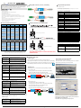
1
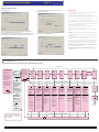
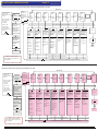
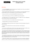
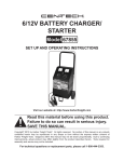
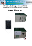
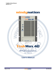
Brushless ESC INSTRUCTION
®
Wiring ESC to motor, receiver, and battery
Thanks to purchase Hifei G-series brushless ESC for R/C electric model airplanes and helicopters.
G-series ESC are high quality controllers at affordable price, there include tiniest 3A to powerful 200A,
there must one appropriate for your airplane’s configuration. G-series ESC support to fully program and
firmware upgradeable by soft on PC. Through upgrading firmware, your ESC will never be obsolete.
Please read this instruction carefully before use. Wish you have a pleasant flight.
Programmable parameters
1 Low Voltage Cut-off (LVC)
Low Cut-off Voltage can protect the main battery from discharged too low, and provide
LV
Features of the Hifei® ESC
the normal operating voltage to receiver and servos.
• form 1 about LVC options for 20A, 40A-G-3S ESC
• Microprocessor controlled
• Extremely low resistance
Option 1:Auto Lipo
Auto Lipo Cells Detecting
• High rate adjustable switching (PWM:8KHz/12KHz/16KHz)
Option2:5.0V(default)
6-8 cell NiCad or NiMH packs, or 2 cell Lithium packs
Option 3:6.0V
8 cell NiCad or NiMH packs, or 2 cell Lithium packs
Option 4:7.2V
9 cell NiCad or NiMH packs
Option 5:8.4V
10 cell NiCad or NiMH packs, or 3 cell Lithium packs
Option 6:9.0V
12 cell NiCad/ NiMH packs, or 3 cell Lithium packs
Option 7:12.0V
4 cell Lithium packs
• Auto Lipo Cells Detecting
• Thermal Protection (100 centigrade)
• Safe “power on” arming program ensures motor will not accidentally turn on.
• Auto shut down when signal is lost or radio interference becomes severe for more than 3 seconds
After radio connection has been reestablished, moving the throttle to the lowest position can
restart the motor.
• Runs motor in forward or reverse by swapping any two motor wire connections.
• Apply to most of inrunner and outrunner brushless motors.
• form 2 about LVC options for 45A, 60A, 80A, 120A-G-6S ESC
• Fully program by Hifei Program card, PC and TX.
• Firmware is upgradeable by PC.
G-series Pro ESC specifications
ESC
Voltage
Current / Max
BEC
Calibrate throttle travel of transmitter
Size(mm)
Weight
(incl. wires)
1st:
Low Voltage ESC
2-3s Lipos
20A-G-3S Pro
6-10s Ni-xx
2-3s Lipos
40A-G-3S Pro
6-10s Ni-xx
2-6s Lipos
45A-G-6S Pro
6-20s Ni-xx
2-6s Lipos
60A-G-6S Pro
6-20s Ni-xx
2-6s Lipos
80A-G-6S Pro
6-20s Ni-xx
2-6s Lipos
120A-G-6S Pro
6-20s Ni-xx
20amp/ 30amp
5V, 2A (linear)
48 x 27 x 10
23g
40amp/ 50amp
5V, 2A (linear)
51.5 x 27x 10.5
25g
45amp/ 65amp
5V, 3.5A
(switching)
58x 26 x 17
40g
5V, 3.5A
(switching)
71 x 26.5 x 15
60amp/ 70amp
2nd: Push the joystick of transmitter to max throttle position, power on the transmitter.
50g
ON
OFF
5V, 3.5A
(switching)
120amp/ 140amp
5V, 3.5A
(switching)
90 x 52 x 16
118g
65amp/ 80amp
Couple-OPTO
83 x 53 x 18
105g
71 x 26.5 x 15
52g
3rd:
4-12s Lipos
12-38s Ni-xx
4-12s Lipos
100A-G-12S Pro 12-38s Ni-xx
4-12s Lipos
150A-G-12S Pro 12-38s Ni-xx
in tune
4th: After the following 2 beeps
High Voltage ESC
65A-G-12S Pro
6-8 cell NiCad or NiMH packs, or 2 cell Lithium packs
)
Option 3:7.2V
8 cell NiCad or NiMH packs, or 2 cell Lithium packs
Option 4:8.4V
9 cell NiCad or NiMH packs
Option 5:9.0V
10 cell NiCad or NiMH packs, or 3 cell Lithium packs
Option 6:12.0V
4 Lipo cells
Option 7:15.0V
5 Lipo cells
Option 8:18.0v
6 Lipo cells
, immediately pull joystick to minimum throttle .
Option 1:Auto Lipo
Option2:12.0v(default)
Auto Lipo Cells Detecting
4 lipo cells
Option 3:15.0v
Option 4:18.0v
5 lipo cells
6 lipo cells
Option 5:21.0v
7 lipo cells
Option 6:24.0v
8 lipo cells
Option 7:27.0V
Option 8:30.0V
Option 9:33.0v
9 Lipo cells
10 Lipo cells
11 Lipo cells
Option10:36.0v
12 lipo cells
2 Current Limiting
100amp/ 120amp Couple-OPTO
83 x 53 x 18
109g
150amp/ 180amp Couple-OPTO
125 x 60 x 38
290g
minimum throttle (it will be zero throttle point)
ON
OFF
4-12s Lipos
200A-G-12S Pro 12-38s Ni-xx 200amp/ 220amp Couple-OPTO 125 x 60 x 38
Note:
Auto Lipo Cells Detecting
Option2:6.0V(default
• form 3 about LVC options for 65A, 100A, 150A, 200A-G-12S ESC
max throttle position (it will be 100% throttle point)
80amp/ 90amp
Option 1:Auto Lipo
emitting, calibrating is finished.
20A, 40A-G-3S ESC are disabled to start when input voltage is over 15V.
NOTE: Default setting is recommended. If you change the setting, damage to the controller as a
result of over current will be not covered by the manufacturer’s warranty.
65A, 100A, 150A, 200A-G-12S ESC are disabled to start when input voltage is over 51V.
Program by soft on PC
Option 1:Brake disabled
(default)
Brake disabled is mainly used for helicopters.
Option 2:Soft brake
Soft brake provides 50% of full braking power. General aircraft
use, with fixed or folding prop
Please download setup software ‘HiFei Vx.0’ from www.hifei.com.
Option 3:Hard brake
Hard brake is 70% braking power. Direct drive applications where
more braking power is required. Hard brake should only be used
below 12V.
The setup soft is checked to be no virus. Please double click it to start installing.
•
Install software
•
Please proceed the installing according to the handling tips in pop-up windows.
When installing is finished, a shortcut icon of the software is auto saved.
Option 1: Low advance
timing 0°~ 15 °(default)
Recommended for more lower pole count motors. Gives more
power and slightly less efficient.
Option 2: middle
advance timing 5 °~ 20
°
Option 3: High advance
timing 15° ~ 30 °
Recommended for most motors .Gives a good balance of power
and efficiency.
Option4:Auto
Recommended for most of all brushless motors.
Recommended for most of higher pole count motors
Moderate over-current threshold, will shut down after a
slight delay. Recommended for inrunner motors.
High over-current threshold, will shut down after a slight
delay. Recommended for outrunner motors. Only
experienced modelers should use this programming
feature
Current limiting detection disabled. Only experienced
modelers should use this programming feature.
Option 4: disabled
5th: 2 beeps
45A, 60A, 80A, 120A-G-6S ESC are disabled to start when input voltage is over 26V.
4 Timing Advance
Low over-current threshold, will rapidly shut-down.
Option
2:Standard(default)
Option 3:Insensitivity
ON
OFF
294g
3 Brake Type
Option 1: Very Sensitivity
•
Open software to change parameters
Double click the shortcut icon of software.
Click ‘Open Device’. If ESC is succeessfully linked to PC, it will auto
jumped to the programming tab, as below pictures:
Link ESC to PC
When link ESC to PC, a Hifei USB Linker (sold separately) is needed.
A. Link LV ESC to PC
1st step: plug the receiver lead of ESC to USB Linker in right polarity,
Option 1 :Hard cutoff
When battery voltage reaches cut-off voltage the motor will
(default)
shutdown immediately. Motor can be restarted by closing the
throttle to the lowest position and then move the throttle as
normal
When battery voltage reaches cut-off voltage, the ESC will
3rd step: the red LED of USB Linker lights, the green LED on ESC lights.
LV ESC
BATT
Option 2: Soft cutoff
2nd step: plug USB Linker into one of USB Ports of ESC.
MOTOR
5 Cutoff Type
USB Linker
slowly reduce motor power to zero , you will notice a decrease in
power and it is time to land, the throttle maintains its full linear.
NOTE: Soft cutoff is always automatically activated in Governor Mode.
6 Soft Start
B. Link HV ESC to PC
Option 1: Very soft start
Recommended for helicopters
Option 2:Soft start (default)
Recommended for most of the fixed or folding prop airplanes,
1st step: Switch off if there is a switch on ESC.
Option 3: Fast start
and some helicopters.
Recommended for fastest startup.
2nd step: plug the receiver lead of ESC to USB Linker in right polarity,
Recommended for collective pitch helicopters. Used for low
pole count motors (Hacker, etc.) and low RPMs on higher pole
5th step: the red LED of USB Linker lights, the green LED on ESC lights.
MOTOR
Recommended for general aircraft
HV
HV ESC
ESC
recognized throttle range of TX
Update button
BATT
Option 3: High RPM
Range
down arrow
3rd step: plug USB Linker into one of USB Ports of ESC.
4th step: connect ESC to battery. Switch on.
7 Governor Mode
Option 1: Auto
calibrating throttle
(default)
Option 2: Low RPM
Range
version ID of ESC
USB Linker
count motors.
Recommended for collective pitch helicopters. Used for higher
pole count motors and higher RPMs.
ON
OFF
Switch
BATT
NOTE: The Governor mode acts as an RPM control. Throttle stick position determines the RPM that the
motor runs and the controller will attempt to hold that RPM regardless of load changes. In Governor Mode,
the brake is always disabled and soft cutoff is automatically active.
- Click down arrow to select the parameter options you would like to set.
- Click ‘Update’ to save modifications.
8 PWM Switching Rate
Option 1: 8 KHz (default)
Recommended for most brushless motors
Option 2: 12 KHz
Recommended for low inductance motors
Option 3: 16 KHz
Recommended for very low inductance motors
- Click ‘Exit’ to finish programming and ready to fly now.
Note: we strongly recommend only the experienced modeler could change this setting.
HIFEI Technology Ltd.
www.hifei.com
G-series ESC INSTRUCTIONS
Page 2
www.hifei.com
Upgrade ESC’s firmware
- Click tab ‘Upgrade’
- Click ‘start’ to begin upgrading. Please wait for a while, it will
Using Notes
be finished within 20 seconds.
• It’s strongly recommended to calibrate the throttle range of your transmitter when you first use the
ESC or when use a new/different transmitter or receiver.
• When connecting the ESC, ensure that the polarity of battery is correct. Incorrect polarity may cause
permanent damage to the ESC and such damage is not covered by the WARRANTY.
• When you use the ESC, turn on the transmitter BEFORE powering on the receiver.
• When you finish the flying, power off the receiver BEFORE turning off the transmitter.
• It is very IMPORTANT to make sure the ESC is mounted in a good air flowing place for heat sinking.
• The limiting current is set to the standard mode in factory. It is suitable for use in most configurations.
Only experienced technicians can adjust this programming.
• In Governor Mode, the brake is always disabled and the soft cutoff is always active.
• Changing the PWM may cause the motor to heat ahead of time.
• Do not play on or near water. Never allow water, moisture or any foreign object onto the PC board of
the ESC.
- Click ‘Browse’ to select the new firmware which the ESC will be upgraded into.
• Damage to the controller as a result of excessively high current is not covered by the manufacturer’s
WARRANTY.
(you can download the firmware from www.hifei.com)
Note: The firmware must be the right one for the specific ESC which will be upgraded.
- ‘Download successful’ , upgrading finished.
• Never disconnect the battery pack while the motor is running, as this could cause damage to the speed
controller and/or motor.
If a ESC is upgraded into a wrong firmware, it would be possibly be damaged.
• Never allow the separate heat sinks to touch each other or any exposed conductive surface. This may
cause short circuit, damage the ESC, and VOID the WARRANTY.
• Connectors with low conductivity may cause erratic motor rotations or other unexpected movements
• If you do not use the BEC function of the ESC and are using a separate receiver battery or UBEC
instead to power receiver and servos, please disconnect the red wire from the ESC’s receiver lead.
• The controller will automatically power off the motor if the battery voltage drops below the
programmed cut-off voltage.Try using a smaller prop on the motor, or using batteries with a higher rating.
It is especially important for the user of Li-poly cells.
• Allowing water, lubricants, moisture or other foreign objects inside the ESC will VOID the
WARRANTY. Exposure to CA glue or its fumes can cause damage and malfunction; this will also
VOID the WARRANTY.
Fully program by TX
Operational Flowchart for Programming 20A, 40A-G-3S ESC by Throttle
Main Loop
7 beeps
Correctly connect
the ESC with
brushless motor
and receiver. Move
There are 4
beeps
emitted from
the motor
indicate you
The 1st
The 2nd
The 3rd
The 4th
The 5th
The 6th
The 7th
The 8th
already have
beep:
beep:
beep:
beep:
beep:
beep:
beep:
beep:
entered the
Low
programmable
Cutoff
Current
Brake
Timing
Cutoff
Start
Governor
PWM
setting
Voltage
Limiting
Type
Advance
Type
Type
Mode
The 10th
reserve
beep:
Switching
Rate
the throttle to the
highest position,
turn on the
transmitter; power
on the ESC. There
are three beeps
emitted from the
motor
Move the
Move the throttle to the lowest position
throttle down to
lowest position,
at this point,
you have
calibrated the
throttle range of
your transmitter
Waiting one
second, there
One beep
indicates you
have entered
the Low
Cutoff
Voltage
Setting.
1st beep:Auto
lipo
1st beep:Very
sensitivity
will be two
2nd beep:5v
beeps emitted
(default)
2nd
beep:Standard
from the motor
3rd beep:6.0v
(default)
4th beep:7.2v
3rd beep:
5th beep:8.4v
Insensitivity
th
6 beep:9.0v
GO FLY
* We recommend to calibrate
your throttle when you first use
the controller.
Two beeps
indicates you
have entered
the Current
Limiting
setting.
th
th
4
beep:Disable
Three beeps
indicates you
have entered
the Brake
Type Setting.
1st beep:Brake
Disable
(default)
2nd beep:Soft
Brake
3rd beep:Hard
Brake
Four beeps
indicates you
have entered
the Timing
Advance
Setting.
1st beep:Low
Advance
2nd
beep:Middle
Advance
rd
3 beep:High
Advance
Five beeps
indicates you
have entered
the Cutoff
Type Setting.
Six beeps
indicates you
have entered
the Soft Start
Setting.
1st beep:Hard
Cutoff (default)
1st beep:Very
Soft Start
2nd beep:Soft
Cutoff
2nd beep:Soft
Start (default)
3rd beep:Fast
Start
4th beep:Auto
Timing
(default)
Seven beeps
indicates you
have entered
the Governor
Mode
Setting.
Eight beeps
indicates you
have entered
the PWM
Switching
Rate Setting.
1st beep:Auto
Calibrating
Throttle
(default)
1st beep:8K
(default)
nd
2 beep:Low
RPM Range
2nd beep:12K
3rd beep:16K
3rd beep:High
RPM Range
GO FLY
7 beep:12v
Move the throttle to the highest position
Three beeps emitted from motor indicated your setting is successful
HIFEI Technology Ltd.
EXIT
www.hifei.com
G-series ESC INSTRUCTIONS
Page 3
www.hifei.com
Operational Flowchart for Programming 45A, 60A, 80A and 120A-G-6S ESC by Throttle
Main Loop
7 beeps
Correctly connect
the ESC with
There are 4
brushless motor and
beeps
receiver.
emitting from
Move the joystick to
the motor
indicate you
The 1st
The 2nd
The 3rd
The 4th
The 5th
The 6th
The 7th
The 8th
already have
beep:
beep:
beep:
beep:
beep:
beep:
beep:
beep:
entered the
Low
programmable
Cutoff
Current
Brake
Timing
Cutoff
Start
Governor
PWM
setting
Voltage
Limiting
Type
Advance
Type
Type
Mode
The 10th
beep:
reserve
Switching
Rate
the max throttle ,
turn on the
transmitter.
Move the
Power on the
throttle down to
receiver, ESC.
the lowest
There are three
position at this
beeps emitted from
period, you
the motor
have calibrated
Move the throttle to the lowest position
One beep
indicates you
have entered
the Low
Cutoff
Voltage
Setting.
the range of
your transmitter
Waiting one
1st beep:Auto
lipo
second, there
Two beeps
indicates you
have entered
the Current
Limiting
setting.
2nd beep:6v
beeps emitted
(default)
2nd
beep:Standard
from the
3rd beep:7.2v
(default)
motor
4th beep:8.4v
3rd beep:
5th beep:9v
Insensitivity
th
6 beep:12v
th
1st beep:Brake
Disable
1st beep:Very
sensitivity
will be two
Four beeps
indicates you
have entered
the Timing
Advance
Setting.
Three beeps
indicates you
have entered
the Brake
Type Setting.
1st beep:Low
Advance
(default)
2nd
beep:Middle
Advance
2nd beep:Soft
Brake
Five beeps
indicates you
have entered
the Cutoff
Type Setting.
Six beeps
indicates you
have entered
the Soft Start
Setting.
1st beep:Hard
Cutoff (default)
1st beep:Very
Soft Start
2nd beep:Soft
Cutoff
2nd beep:Soft
Start (default)
3 beep:High
Advance
3rd beep:Hard
Brake
4
beep:Disable
1st beep:Auto
Calibrating
Throttle
(default)
1st beep:8K
(default)
2 beep: Low
RPM Range
EXIT
2nd beep:12K
3rd beep:16K
3rd beep: High
RPM Range
4th beep:Auto
Timing
(default)
th
Eight beeps
indicates you
have entered
the PWM
Switching
Rate Setting.
nd
3rd beep:Fast
Start
rd
Seven beeps
indicates you
have entered
the Governor
Mode
Setting.
GO FLY
7 beep:15v
GO FLY
8th beep:18v
Move the throttle to the highest position
* We recommend to calibrate
your throttle when you first use
Three beeps emitted from motor indicated your setting is successful
the controller.
Operational Flowchart for Programming HV ESC by Throttle
Main Loop
7 beeps
Correctly connect
the ESC with
brushless motor and
receiver.
Move the joystick to
There are 4
long beeps
emitted from
the motor
indicate you
The 1st
already have
beep:
entered the
Low
programmable
Cutoff
setting
Voltage
The 3rd
The 2nd
The 4th
The 5th
The 6th
The 7th
The 8th
beep:
PWM
beep:
beep:
beep:
beep:
beep:
beep:
Current
Brake
Timing
Cutoff
Start
Governor
Limiting
Type
Advance
Type
Type
Mode
The 10th
reserve
beep:
Switching
Rate
the max throttle ,
turn on the
transmitter.
Power on the
receiver, ESC.
There are three
beeps emitted from
the motor
Move the
Move the throttle to the lowest position
throttle down to
lowest position,
at this point,
you have
calibrated the
your transmitter
One beep
indicates you
have entered
the Low
Cutoff
Voltage
Setting.
Waiting one
1st beep:Auto lipo
second, there
2nd beep:4S
will be two
(default)
throttle range of
beeps emitted
from the
motor
rd
3 beep:5S
4th beep:6S
5th beep:7S
6th beep:8S
7th beep:9S
th
8 beep:10S
GO FLY
* We recommend to calibrate
your throttle when you first use
the controller.
9th beep:11S
Two beeps
indicates you
have entered
the Current
Limiting
setting.
1st beep:Brake
Disable
1st beep:Very
sensitivity
2nd
beep:Standard
(default)
3rd beep:
Insensitivity
th
4
beep:Disable
Three beeps
indicates you
have entered
the Brake
Type Setting.
(default)
2nd beep:Soft
Brake
rd
3 beep:Hard
Brake
Four beeps
indicates you
have entered
the Timing
Advance
Setting.
1st beep:Low
Advance
2nd
beep:Middle
Advance
rd
3 beep:High
Advance
Five beeps
indicates you
have entered
the Cutoff
Type Setting.
Six beeps
indicates you
have entered
the Soft Start
Setting.
1st beep:Hard
Cutoff (default)
1st beep:Very
Soft Start
2nd beep:Soft
Cutoff
2nd beep:Soft
Start (default)
rd
3 beep:Fast
Start
4th beep:Auto
Timing
(default)
Seven beeps
indicates you
have entered
the Governor
Mode
Setting.
Eight beeps
indicates you
have entered
the PWM
Switching
Rate Setting.
1st beep:Auto
Calibrating
Throttle
(default)
1st beep:Low
(default)
nd
2 beep:Low
RPM Range
2nd
beep:Middle
3rd beep:High
3rd beep:High
RPM Range
GO FLY
10th beep:12S
Move the throttle to the highest position
Three beeps emitted from motor indicated your setting is successful
HIFEI Technology Ltd.
EXIT
www.hifei.com