Download Desa CGCF26TP User's Manual
Transcript
VENT-FREE PROPANE/LP GAS COMPACT FIREPLACE OWNER’S OPERATION AND INSTALLATION MANUAL ® Shown with Optional Cabinet Mantel/Hearth Base Accessory 14,000 to 26,000 Btu/Hr with Thermostat CGCF26TP WARNING: If the information in this manual is not followed exactly, a fire or explosion may result causing property damage, personal injury, or loss of life. — Do not store or use gasoline or other flammable vapors and liquids in the vicinity of this or any other appliance. — WHAT TO DO IF YOU SMELL GAS • Do not try to light any appliance. • Do not touch any electrical switch; do not use any phone in your building. • Immediately call your gas supplier from a neighbor’s phone. Follow the gas supplier’s instructions. • If you cannot reach your gas supplier, call the fire department. — Installation and service must be performed by a qualified installer, service agency, or the gas supplier. WARNING: Improper installation, adjustment, alteration, service, or maintenance can cause injury or property damage. Refer to this manual for correct installation and operational procedures. For assistance or additional information consult a qualified installer, service agency, or the gas supplier. WARNING: This is an unvented gas-fired heater. It uses air (oxygen) from the room in which it is installed. Provisions for adequate combustion and ventilation air must be provided. Refer to Air for Combustion and Ventilation section on page 6 of this manual. This appliance may be installed in an aftermarket* manufactured (mobile) home, where not prohibited by state or local codes. *Aftermarket: Completion of sale, not for purpose of resale, from the manufacturer. (I.E. Installation of this product is permitted after the manufactured (mobile) home is sited) This appliance is only for use with the type of gas indicated on the rating plate. This appliance is not convertible for use with other gases. Save this manual for future reference. CONTENTS SECTION PAGE Safety Information ................................................................................... 2 Product Identification .............................................................................. 4 Local Codes ............................................................................................. 4 Product Features ...................................................................................... 4 Unpacking ................................................................................................ 4 Assembly ................................................................................................. 4 Air for Combustion and Ventilation ........................................................ 6 Installation ............................................................................................... 10 Connecting to Gas Supply ....................................................................... 16 Checking Gas Connections ...................................................................... 18 Operating Fireplace ................................................................................. 20 Inspecting Burner .................................................................................... 23 Cleaning and Maintenance ...................................................................... 25 Troubleshooting ....................................................................................... 25 Technical Service .................................................................................... 29 Specifications .......................................................................................... 29 Service Hints ........................................................................................... 29 Replacement Parts ................................................................................... 29 Illustrated Parts List ................................................................................. 30, 31 Accessories .............................................................................................. 32 Parts Centrals ........................................................................................... 33 Warranty Information .............................................................................. 36 SAFETY INFORMATION WARNING ICON G 001 WARNINGS IMPORTANT: Read this owner’s manual carefully and completely before trying to assemble, operate, or service this fireplace. Improper use of this fireplace can cause serious injury or death from burns, fire, explosion, electrical shock, and carbon monoxide poisoning. WARNING ICON G 001 DANGER Carbon monoxide poisoning may lead to death! Carbon Monoxide Poisoning: Early signs of carbon monoxide poisoning resemble the flu, with headaches, dizziness, or nausea. If you have these signs, the fireplace may not be working properly. Get fresh air at once! Have fireplace serviced. Some people are more affected by carbon monoxide than others. These include pregnant women, people with heart or lung disease or anemia, those under the influence of alcohol, and those at high altitudes. Propane/LP Gas: Propane/LP gas is odorless. An odor-making agent is added to propane/LP gas. The odor helps you detect a propane/LP gas leak. However, the odor added to propane/LP gas can fade. Propane/LP gas may be present even though no odor exists. Make certain you read and understand all warnings. Keep this manual for reference. It is your guide to safe and proper operation of this fireplace. 2 Safety Information continues on next page 103667 SAFETY INFORMATION Continued . WARNING ICON G 001 WARNINGS Continued WARNING: Any change to this fireplace or its controls can be dangerous. 1. This appliance is only for use with the type of gas indicated on the rating plate. This appliance is not convertible for use with other gases. 2. Do not place propane/LP supply tank(s) inside any structure. Locate propane/LP supply tank(s) outdoors. 3. If you smell gas • shut off gas supply • do not try to light any appliance • do not touch any electrical switch; do not use any phone in your building • immediately call your gas supplier from a neighbor’s phone. Follow the gas supplier’s instructions • if you cannot reach your gas supplier, call the fire department 4. This fireplace shall not be installed in a bedroom or bathroom. 5. Never install the fireplace • in a recreational vehicle. • where curtains, furniture, clothing, or other flammable objects are less than 36 inches from the front, top, or sides of the fireplace. • as a fireplace insert. • in high traffic areas. • in windy or drafty areas. 6. Do not use this fireplace as a wood-burning fireplace. Use only the logs provided with the fireplace. 7. Do not add extra logs or ornaments such as pine cones, vermiculite, or rock wool. Using these added items can cause sooting. Do not add lava rock around base. Rock and debris could fall into the control area of fireplace. 8. You must operate this fireplace with the fireplace screen in place. Make sure fireplace screen is in place before running fireplace. 9. This fireplace is designed to be smokeless. If logs ever appear to smoke, turn off fireplace and call a qualified service person. Note: During initial operation, slight smoking could occur due to log curing and fireplace burning manufacturing residues. 10. Do not allow fans to blow directly into the fireplace. Avoid any drafts that alter burner flame patterns. Ceiling fans can create drafts that alter burner flame patterns. Altered burner patterns can cause sooting. 11. This fireplace needs fresh air ventilation to run properly. This fireplace has an oxygen depletion sensor (ODS) pilot light safety system. The ODS shuts down the fireplace if not enough fresh air is available. See Air for Combustion and Ventilation, pages 6 through 9. If fireplace keeps shutting off, see Troubleshooting, pages 24 through 27. 12. Do not run fireplace • where flammable liquids or vapors are used or stored. • under dusty conditions. 13. Do not use this fireplace to cook food or burn paper or other objects. 14. Never place any objects in the fireplace or on logs. 15. Fireplace front and screen becomes very hot when running fireplace. Keep children and adults away from hot surfaces to avoid burns or clothing ignition. Fireplace will remain hot for a time after shut-down. Allow surfaces to cool before touching. 16. Carefully supervise young children when they are in same room with fireplace. 17. Do not use fireplace if any part has been under water. Immediately call a qualified service technician to inspect the room fireplace and to replace any part of the control system and any gas control which has been under water. 18. Turn off and unplug fireplace and let cool before servicing. Only a qualified service person should service and repair fireplace. 19. Operating fireplace above elevations of 4,500 feet could cause pilot outage. 20. Do not use a blower insert, heat exchanger insert, or other accessory not approved for use with this fireplace. 21. Do not operate fireplace if any log is broken. Do not operate fireplace if a log is chipped (dime-sized or larger). 22. To prevent performance problems, do not use propane fuel tank of less than 100 lbs. capacity. 3 103667 PRODUCT IDENTIFICATION Fireplace Cabinet Screen Logs Control Knob Ignitor Button Figure 1 - Vent-Free Propane/LP Gas Compact Fireplace LOCAL CODES Install and use fireplace with care. Follow all local codes. In the absence of local codes, use the latest edition of The National Fuel Gas Code ANSI Z223, also known as NFPA 54*. *Available from: American National Standards Institute, Inc. 1430 Broadway New York, NY 10018 National Fire Protection Association, Inc. Batterymarch Park Quincy, MA 02269 PRODUCT FEATURES Safety Pilot This fireplace has a pilot with an Oxygen Depletion Sensor Shutoff System (ODS). The ODS/pilot is a required feature for vent-free room fireplaces. The ODS/pilot shuts off the fireplace if there is not enough fresh air. Piezo Ignition System This fireplace has a piezo ignitor. This system requires no matches, batteries, or other sources to light fireplace. Thermostatic Heat Control This fireplace has a thermostat sensing bulb and a control valve. The thermostat will automatically modulate the heat output to maintain a consistent room temperature. This results in greater fireplace comfort. This can also result in lower gas bills. UNPACKING 1. 2. 3. 4. Remove log box and fireplace from carton. The hood is not attached. Remove all protective packaging applied to fireplace for shipment. Make sure your fireplace includes one hardware packet. Check fireplace for any shipping damage. If fireplace is damaged, promptly inform dealer where you bought fireplace. ASSEMBLY WARNING ICON G 001 WARNING Always have branch support and screen in place before operating fireplace. This prevents excessive temperatures on fireplace surfaces. 4 103667 ASSEMBLY Continued ASSEMBLING FIREPLACE Tools Required: Phillips screwdriver, 5/16" hex wrench, and slotted screwdriver Installing Log 1. Remove back log, branch, and hood from log box. Discard protective packaging. 2. Remove two shipping screws above screen (see Figure 2). 3. Lift screen up and pull out to remove. 4. An optional blower is available. See Accessories, page 32. Install optional blower now. Follow installation instructions provided with blower. 5. Gently place back log on burner support (see Figure 2). The log should fit flat against top of burner support. Place two #10 one-inch-long screws through burner support into the log and tighten. Place branches on branch support (see Figure 2). 6. Reattach screen by placing notches in screen frame over shoulder screws and pushing down. Screen Shipping Screw Shoulder Screw Back Log Burner Support Screw Branch Support Screen Screw Branch Figure 2 - Assembling Fireplace WARNING ICON G 001 WARNING Failure to position the parts in accordance with these diagrams or failure to use only parts specifically approved with this fireplace may result in property damage or personal injury. Assembling Hood 1. Lift screen off heater. 2. Remove two 1-3/4" screws from louver assembly (see Figure 2). Save these screws. Upper Louver Assembly 2 Short Screws 1-3/4" Screws Figure 3 - Assembling Hood 3. Pull louver assembly straight out from the cabinet. Be careful not to scratch the paint. Set louver assembly and screws aside. 4. Locate two black Phillips sheet metal screws from the hardware packet. 5. Place hood over top edge of firebox wrapper. 6. Attach hood with two short screws in center of hood. 7. Replace upper and lower assembly and 1-3/4" screws removed in step 2. 103667 5 AIR FOR COMBUSTION AND VENTILATION WARNING ICON G 001 WARNING This heater shall not be installed in a confined space unless provisions are provided for adequate combustion and ventilation air. Read the following instructions to insure proper fresh air for this and other fuel-burning appliances in your home. Today’s homes are built more energy efficient than ever. New materials, increased insulation, and new construction methods help reduce heat loss in homes. Home owners weather strip and caulk around windows and doors to keep the cold air out and the warm air in. During heating months, home owners want their homes as airtight as possible. While it is good to make your home energy efficient, your home needs to breathe. Fresh air must enter your home. All fuel-burning appliances need fresh air for proper combustion and ventilation. Exhaust fans, fireplaces, clothes dryers, and fuel burning appliances draw air from the house to operate. You must provide adequate fresh air for these appliances. This will insure proper venting of vented fuel-burning appliances. PROVIDING ADEQUATE VENTILATION The following is excerpts from National Fuel Gas Code. NFPA 54/ANSI Z223.1, Section 5.3, Air for Combustion and Ventilation. All spaces in homes fall into one of the three following ventilation classifications: 1. Unusually Tight Construction; 2. Unconfined Space; 3. Confined Space. The information on pages 6 through 9 will help you classify your space and provide adequate ventilation. Unusually Tight Construction The air that leaks around doors and windows may provide enough fresh air for combustion and ventilation. However, in buildings of unusually tight construction, you must provide additional fresh air. Unusually tight construction is defined as construction where: a. walls and ceilings exposed to the outside atmosphere have a continuous water vapor retarder with a rating of one perm (10-6 per-pa-m2) or less with openings gasketed or sealed and b. weather stripping has been added on openable windows and doors and c. caulking or sealants are applied to areas such as joints around window and door frames, between sole plates and floors, between wall-ceiling joints, between wall panels, at penetrations for plumbing, electrical, and gas lines, and at other openings. If your home meets all of the three criteria above, you must provide additional fresh air. See Ventilation Air From Outdoors, page 9. If your home does not meet all of the three criteria above, proceed to page 7. 6 Confined and Unconfined Space The National Fuel Gas Code (ANSIZ223.1, 1992 Section 5.3) defines a confined space as a space whose volume is less than 50 cubic feet per 1,000 Btu per hour (4.8 m3 per kw) of the aggregate input rating of all appliances installed in that space and an unconfining space as a space whose volume is not less than 50 cubic feet per 1,000 Btu per hour (4.8 m3 per kw) of the aggregate input rating of all appliances installed in that space. Rooms communicating directly with the space in which the appliances are installed*, through openings not furnished with doors, are considered a part of the unconfined space. * Adjoining rooms are communicating only if there are doorless passageways or ventilation grills between them. 103667 AIR FOR COMBUSTION AND VENTILATION Continued DETERMINING FRESH-AIR FLOW FOR FIREPLACE LOCATION Determining if You Have a Confined or Unconfined Space Use this worksheet to determine if you have a confined or unconfined space. Space: Includes the room in which you will install fireplace plus any adjoining rooms with doorless passageways or ventilation grills between the rooms. 1. Determine the volume of the space (length x width x height). Length x Width x Height = ___________________ cu. ft. (volume of space) Example: Space size 20 ft. (length) x 16 ft. (width) x 8 ft. (ceiling height) = 2560 cu. ft. (volume of space) If additional ventilation to adjoining room is supplied with grills or openings, add the volume of these rooms to the total volume of the space. 2. Divide the space volume by 50 cubic feet to determine the maximum Btu/Hr the space can support. ____________ (volume of space) ÷ 50 cu. ft. = (Maximum Btu/Hr the space can support) Example: 2560 cu. ft. (volume of space) ÷ 50 cu. ft. = Btu/Hr the space can support) 51.2 or 51,200 (maximum 3. Add the Btu/Hr of all fuel burning appliances in the space. Vent-free fireplace Gas water heater* Gas furnace Vented gas heater Gas fireplace logs Other gas appliances* Total ___________________ Btu/Hr ___________________ Btu/Hr ___________________ Btu/Hr ___________________ Btu/Hr ___________________ Btu/Hr + ___________________ Btu/Hr = ___________________ Btu/Hr Example: Gas water heater 30,000 Btu/Hr Vent-free fireplace + 26,000 Btu/Hr Total = 56,000 Btu/Hr * Do not include direct-vent gas appliances. Direct-vent draws combustion air from the outdoors and vents to the outdoors. 4. Compare the maximum Btu/Hr the space can support with the actual amount of Btu/Hr used. _________________ Btu/Hr (maximum the space can support) _________________ Btu/Hr (actual amount of Btu/Hr used) Example: 51,200 56,000 Btu/Hr (maximum the space can support) Btu/Hr (actual amount of Btu/Hr used) The space in the above example is a confined space because the actual Btu/Hr used is more than the maximum Btu/Hr the space can support. You must provide additional fresh air. Your options are as follows: A. Rework worksheet, adding the space of an adjoining room. If the extra space provides an unconfined space, remove door to adjoining room or add ventilation grills between rooms. See Ventilation Air From Inside Building, page 8. B. Vent room directly to the outdoors. See Ventilation Air From Outdoors, page 9. C. Install a lower Btu/Hr fireplace, if lower Btu/Hr size makes room unconfined. If the actual Btu/Hr used is less than the maximum Btu/Hr the space can support, the space is an unconfined space. You will need no additional fresh air ventilation. 7 103667 AIR FOR COMBUSTION AND VENTILATION Continued WARNING ICON G 001 WARNING If the area in which the heater may be operated is smaller than that defined as an unconfined space, provide adequate combustion and ventilation air by one of the methods described in the National Fuel Gas Code, ANSI Z223.1, 1992, Section 5.3 or applicable local codes. VENTILATION AIR Ventilation Air From Inside Building This fresh air would come from an adjoining unconfined space. When ventilating to an adjoining unconfined space, you must provide two permanent openings: one within 12" of the ceiling and one within 12" of the floor on the wall connecting the two spaces (see options 1 and 2, Figure 4). You can also remove door into adjoining room (see option 3, Figure 4). Follow the National Fuel Gas Code NFPA 54/ANSI Z223.1, Section 5.3, Air for Combustion and Ventilation for required size of ventilation grills or ducts. WARNING ICON G 001 WARNING Rework worksheet, adding the space of the adjoining unconfined space. The combined spaces must have enough fresh air to supply all appliances in both spaces. 12" Ventilation Grills into Adjoining Room, Option 1 Ventilation Grills Into Adjoining Room, Option 2 Or Remove Door into Adjoining Room, Option 3 12" Figure 4 - Ventilation Air from Inside Building Shown with Optional Mantel 8 103667 AIR FOR COMBUSTION AND VENTILATION Continued Ventilation Air From Outdoors Provide extra fresh air by using ventilation grills or ducts. You must provide two permanent openings: one within 12" of the ceiling and one within 12" of the floor. Connect these items directly to the outdoors or spaces open to the outdoors. These spaces include attics and crawl spaces. IMPORTANT: Do not provide openings for inlet or outlet air into attic if attic has a thermostat-controlled power vent. Heated air entering the attic will activate the power vent. Outlet Air Outlet Air Ventilated Attic To Attic To Crawl Space Inlet Air Inlet Air Ventilated Crawl Space Figure 5 - Ventilation Air from Outdoors Shown with Optional Mantel 9 103667 INSTALLATION NOTICE A qualified service person must install fireplace. Follow all local codes. CHECK GAS TYPE Use only propane/LP gas. If your gas supply is not propane/LP, do not install fireplace. Call dealer where you bought fireplace for proper type fireplace. INSTALLATION ITEMS Before installing fireplace, make sure you have the items listed below. • external regulator (supplied by • sealant (resistant to • sediment trap installer, see page 16) propane/LP gas) • tee joint • piping (check local codes) • manual shutoff valve * • pipe wrench • ground joint union * An A.G.A. design-certified manual shutoff valve with 1/8" NPT tap is an acceptable alternative to test gauge connection. Purchase the optional A.G.A. design-certified manual shutoff valve from your dealer. See Accessories, page 32. Note: If desired, purchase a four-sided brass trim kit for built-in installations. See Accessories, page 32. LOCATING FIREPLACE WARNING ICON WARNING G 001 Maintain the minimum clearances shown in Figures 6 and 7 (page 11). If you can, provide greater clearances from floor, ceiling, and joining wall. You can recess firebox into the wall. You can also position fireplace in the optional cabinet or corner mantels. IMPORTANT: Only use optional cabinet or corner mantels specified in this manual. Purchase the optional mantel from your dealer (see Accessories, page 32). WARNING ICON G 001 WARNING Never install the fireplace • in a bedroom or a bathroom • in a recreational vehicle • where curtains, furniture, clothing, or other flammable objects are less than 36 inches from the front, top, or sides of the fireplace • as a fireplace insert • in high traffic areas • in windy or drafty areas WARNING ICON G 001 CAUTION This fireplace creates warm air currents. These currents move heat to wall surfaces next to fireplace. Installing fireplace next to vinyl or cloth wall coverings or operating fireplace where impurities in the air (such as tobacco smoke) exist, may discolor walls. 10 IMPORTANT: Vent-free fireplaces add moisture to the air. Although this is beneficial, installing fireplace in rooms without enough ventilation air may cause mildew to form from too much moisture. See Air for Combustion and Ventilation, pages 6 through 9. 103667 INSTALLATION WARNING ICON Continued G 001 CAUTION If you install the fireplace in a home garage • fireplace pilot and burner must be at least 18 inches above floor. • locate fireplace where moving vehicle will not hit it. For convenience and efficiency, install fireplace • where there is easy access for operation, inspection, and service. • in coldest part of room. An optional blower kit is available from your dealer. See Accessories, page 32. If planning to use blower, locate fireplace near an electrical outlet. CEILING 36" Minimum 6" Minimum From Sides Of Fireplace Right Side Left Side FLOOR Figure 6 - Mounting Clearances As Viewed From Front of Fireplace Shown Built In The Wall CEILING 36" Minimum Top Of Mantel Can Be Flush With Wall Left Side Right Side Figure 7 - Mounting Clearances As Viewed From Front of Fireplace Shown with Optional Mantel 103667 11 INSTALLING Continued BUILT-IN FIREPLACE INSTALLATION Built-in installation of this fireplace involves installing fireplace into a framed-in enclosure. This makes the front of fireplace flush with wall. An optional brass trim kit accessory is available (see Accessories, page 32). Brass trim will extend past sides of fireplace approximately 1/2 inch. This will cover the rough edges of the wall opening. If installing a built-in mantel above the fireplace, but you must follow the clearances shown in Figure 11, page 13. Follow the instructions below to install the fireplace in this manner. Height Front Width Actual Framing 26" 7 26 /8" Actual 3 26 /4" Depth Framing 7 26 /8" Actual 1 9 /2" Bottom Framing 1 10 /2" Actual Framing 3 /4" 3 /4" * The additional space is for piping 1. Frame in rough opening. Use dimensions shown in Figure 8 for the rough opening. 10 1/2" 26 7/8" 26 7/8" 3/4" Off The Floor Minimum Figure 8 - Rough Opening for Installing in Wall If installing in a corner, use dimensions shown in Figure 9 for the rough opening. The height is 26 1/8" which is the same as the wall opening above. 36 5/8" 25 7/8" 26 7/8" 51 3/4" Figure 9 - Rough Opening for Installing in Corner 12 2. An optional blower accessory is available (see Accessories, page 32). There are two options for connecting blower to electrical source. Option one: Have a licensed electrician install a properly grounded, threeprong 120-volt electrical outlet at fireplace location. Locate outlet inside the framed enclosure. Blower power cord will plug into this outlet. Option two: Have a licensed electrician connect blower to electrical source at junction box inside fireplace. If using option one, have electrical outlet installed at this time. If using option two, do not connect blower to electrical source at junction box until step 7. 3. Install gas piping to fireplace location. This installation includes an approved flexible gas line (if allowed by local codes) after the manual shutoff valve. The flexible gas line must be the last item installed on the gas piping. 4. If you have not assembled firebox, follow instructions on page 5. 5. Carefully set fireplace in front of rough opening with back of fireplace inside wall opening. 103667 INSTALLING Continued 6. Attach flexible gas line to fireplace gas regulator. See Connecting Fireplace to Gas Supply, page 17. 7. If the optional blower has been installed connect blower to electrical source. Option one: Route blower electrical cord through side or rear access door of fireplace. Plug electrical cord into electrical outlet. Option two: Have a licensed electrician connect blower to electrical source at junction box inside fireplace. 8. Bend four nailing flanges on outer casing with pliers (see Figure 10). 9. Attach fireplace to wall studs using nails or wood screws through holes in nailing flange. Nails or Wood Screws Nailing Flanges Figure 10 - Attaching Fireplace to Wall Studs 10. Check all gas connections for leaks. See Checking Gas Connections, page 17. 11. If using optional brass trim kit, install the trim after final finishing and/or painting of wall. See instructions included with brass trim accessory for attaching brass trim. Mantel Clearances for Built-In Installation If placing mantel above built-in fireplace, you must meet minimum clearance between mantel shelf and top of fireplace opening. Mantel Shelf 10" Underside of Mantel Shelf 8" 6" 2 1/2" All minimum distances are in inches Side of Firebox 20" 241/2" 271/2" Distances to Underside of Built-in Mantel 30" Top of Fireplace Opening Figure 11 - Minimum Mantel Clearances for Built-In Installation If your installation does not meet the above minimum clearances, you must: • raise the mantel to an acceptable height, OR • remove the mantel. Continued 103667 13 INSTALLING Continued OPTIONAL MANTEL INSTALLATION Note: Refer to instructions provided with the mantel for assembly instructions. Refer to instructions below for system installation. Refer to instructions on page 5 for firebox assembly. Blower accessory should be installed if it is being used (see Accessories, page 32). 1. Unscrew four brass screws that attach top louver to fireplace. Remove louvre from fireplace and set aside. 2. Place fireplace on wood base. 3. Place mantel around fireplace/base assembly. 4. Assemble brass trim kit. See Assembling Brass Trim, page 15. 5. Firmly snap brass trim kit on shoulder screws. Shoulder screws are located on fireplace cabinet (see Figure 12). 6. Align brass trim kit for flush fit around opening. 7. Use two 3" wood screws provided and attach fireplace base to wooden base (see Figure 12). Shoulder Screws Hole for 3" wood screw for attaching fireplace to mantel Assembled Brass Trim Hole for 3" wood screw for attaching fireplace to wooden base Figure 12 - Attaching Brass Trim to Fireplace 8. Remove brass trim kit and mantel. Be careful not to damage wall or mantel. 9. Place wood base next to wall at installation location. 10. Attach wood base to floor with two 1 3/4" black screws provided (see Figure 13). If the floor is concrete use anchor method (see Attaching Wood Base to Solid Floor, page 15). 1 3/4" Screw Wood Base Figure 13 - Attaching Wood Base to Floor 11. 12. 13. 14. 14 Install gas line. See Connecting To Gas Supply, pages 16-18. Check for leaks. See Checking Gas Connections, page 18. Place mantel around fireplace. Be careful not to damage wall or mantel. Place brass trim kit on the shoulder screws located on the side and top of the fireplace. Firmly snap the brass trim over the shoulder screws on fireplace (see Figure 12). 15. Adjust assembly to remove any gaps. Attach remaining two 3" wood screws from hardware pack through openings inside of fireplace sides into the mantel. The openings are located at top behind the area for the brass louvers (see Figure 13). 16. Reinstall top brass louvers. 103667 INSTALLING Continued Assembling Brass Trim (Brass trim shipped with mantel) 1. Remove packaging from three remaining pieces of brass trim. 2. Locate two adjusting plates with set screws, and two shims in the hardware packet. 3. Align shim under adjusting plate as shown in Figure 14. 4. Slide one end of adjusting plate/shim in slot on mitered edge of top brass trim (see Figure 14). 5. Slide other end of adjusting plate/shim in slot on mitered edge of side brass trim (see Figure 14). 6. While firmly holding edges of brass trim together, tighten both set screws on the adjusting plate with slotted screwdriver. 7. Repeat steps 1 through 6 for other corner. 8. Set Brass Assembly aside for later installation. Top Brass Trim Set Screws Slot Adjusting Plate Shim Mitered Edge Side Brass Trim Slot Figure 14 - Assembling Brass Trim Attaching Wood Base to Solid Floor For attaching base to solid floors (concrete or masonry) Note: Floor anchors and mounting screws are in hardware package. The hardware package is provided with fireplace. 1. Drill holes at marked locations using 5/16" drill bit. For solid floors (concrete or masonry), drill at least 1" deep. 2. Fold floor anchor as shown in Figure 15. Figure 15 - Folding Anchor 3. Insert floor anchor (wings first) into hole. Tap anchor flush to floor. 4. Insert mounting screws through base and into floor anchors. 5. Tighten screws until base is firmly fastened to floor. 15 103667 CONNECTING TO GAS SUPPLY NOTICE A qualified service person must connect fireplace to gas supply. Follow all local codes. WARNING ICON G 001 CAUTION Never connect fireplace directly to the propane/LP supply. This fireplace requires an external regulator (not supplied). Install the external regulator between the fireplace and propane/LP supply. The installer must supply an external regulator. The external regulator will reduce incoming gas pressure. You must reduce incoming gas pressure to between 11 and 14 inches of water. If you do not reduce incoming gas pressure, fireplace regulator damage could occur. Install external regulator with the vent pointing down as shown in Figure 16. Pointing the vent down protects it from freezing rain or sleet. Propane/LP Supply Tank External Regulator Vent Pointing Down Figure 16 - External Regulator with Vent Pointing Down WARNING ICON G 001 CAUTION Use only new, black iron or steel pipe. Internally-tinned copper tubing may be used in certain areas. Check your local codes. Use pipe of 1/2" or greater diameter to allow proper gas volume to fireplace. If pipe is too small, undue loss of pressure will occur. Installation must include a manual shutoff valve, union, and plugged 1/8" NPT tap. Locate NPT tap within reach for test gauge hook up. NPT tap must be upstream from fireplace (see Figure 17, page 17). Apply pipe joint sealant lightly to male threads. This will prevent excess sealant from going into pipe. Excess sealant in pipe could result in clogged fireplace valves. WARNING ICON G 001 CAUTION Use pipe joint sealant that is resistant to liquid petroleum (LP) gas. Install sediment trap in supply line as shown in Figure 17, page 17. Locate sediment trap where it is within reach for cleaning. Locate sediment trap where trapped matter is not likely to freeze. A sediment trap traps moisture and contaminants. This keeps them from going into fireplace controls. If sediment trap is not installed or is installed wrong, fireplace may not run properly. 16 103667 A.G.A. Design-Certified Manual Shutoff Valve With 1/8" NPT Tap* CONNECTING TO GAS SUPPLY Approved Flexible Gas Line Continued From External Regulator (11" W.C. to 14" W.C. Pressure) 3" Minimum Tee Joint Sediment Trap Pipe Nipple Figure 17 - Gas Connection Cap * Purchase the optional A.G.A. design-certified manual shutoff valve from your dealer. See Accessories, page 32. CONNECTING FIREPLACE TO GAS SUPPLY Installation Items Needed • Phillips screwdriver • sealant (resistant to propane gas, not provided) 1. Remove fireplace screen. Remove two screws that hold fireplace screen in place for shipping. These screws are located near top of screen. Discard screws. Lift fireplace screen up and pull out to remove. 2. Remove screws that attach branch support to fireplace (see Figure 18). Carefully lift up branch support and remove from fireplace (see Figure 18). Screen Shipping Screw Branch Support Shoulder Screw Screen Flexible Gas Line Figure 18 - Removing Log Base Assembly From Fireplace 3. Route flexible gas line from manual shutoff valve into fireplace through side or rear access holes in outer casing. Route flexible gas supply line through fireplace access holes in outer casing. NOTICE Most building codes do not permit concealed gas connections. A flexible gas line is provided to allow accessibility from the fireplace. The flexible gas supply line connection to the manual shutoff valve should be accessible. 17 103667 
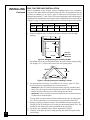
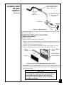
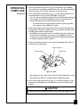
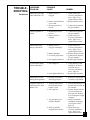
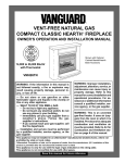
CONNECTING TO GAS SUPPLY Continued 4. Apply pipe joint sealant lightly to male threads of gas connector attached to flexible gas line (see Figure 19). Connect flexible gas line to flexible gas line attached to gas regulator of fireplace (see Figure 19). 5. Check all gas connections for leaks. See Checking Gas Connections, below. 6. Replace branch support back into fireplace. Feed flexible gas line into fireplace base area while replacing branch support. Make sure the entire flexible gas line is in fireplace base area. Reattach branch support to fireplace with screws removed in step 3. To Fireplace Gas Regulator ➞ Flexible Gas Line from Fireplace Gas Regulator Gas Connector Manual Shutoff Valve To Gas Supply Flexible Gas Line from Manual Shutoff Valve ➞ Figure 19 - Attaching Flexible Gas Lines Together CHECKING GAS CONNECTIONS WARNING ICON G 001 WARNING Test all gas piping and connections for leaks after installing or servicing. Correct all leaks at once. WARNING ICON G 001 WARNING Never use an open flame to check for a leak. Apply a mixture of liquid soap and water to all joints. Bubbles forming show a leak. Correct all leaks at once. WARNING ICON G 001 CAUTION Make sure external regulator has been installed between propane/ LP supply and fireplace. See guidelines under Connecting to Gas Supply, page 16. PRESSURE TESTING GAS SUPPLY PIPING SYSTEM Test Pressures In Excess Of 1/2 PSIG 1. Disconnect fireplace and its individual manual shutoff valve from gas supply piping system. Pressures in excess of 1/2 psig will damage fireplace regulator. 2. Cap off open end of gas pipe where manual shutoff valve was connected. 3. Pressurize supply piping system by either using compressed air or opening propane/LP supply tank valve. 4. Check all joints of gas supply piping system. Apply mixture of liquid soap and water to gas joints. Bubbles forming show a leak. 5. Correct all leaks at once. 18 103667 CHECKING GAS CONNECTIONS Continued Test Pressures Equal To or Less Than 1/2 PSIG 1. Close manual shutoff valve (see Figure 20). 2. Pressurize supply piping system by either using compressed air or opening propane/LP supply tank valve. 3. Check all joints from propane/LP supply tank to manual shutoff valve (see Figure 21). Apply mixture of liquid soap and water to gas joints. Bubbles forming show a leak. 4. Correct all leaks at once. PRESSURE TESTING FIREPLACE GAS CONNECTIONS 1. 2. 3. 4. 5. 6. 7. 8. Open manual shutoff valve (see Figure 20). Open propane/LP supply tank valve. Make sure control knob of fireplace is in the OFF position. Check all joints from manual shutoff valve to thermostat gas valve (see Figure 19). Apply mixture of liquid soap and water to gas joints. Bubbles forming show a leak. Correct all leaks at once. Light fireplace (see Operating Fireplace, pages 20 through 22). Check all other internal joints for leaks. Turn off fireplace (see To Turn Off Gas to Appliance, page 22). Replace front panel. Open ON POSITION Manual Shutoff Valve OFF POSITION Closed Figure 20 - Manual Shutoff Valve Propane/LP Supply Tank Manual Shutoff Valve Figure 21 - Checking Gas Joints Shown with Optional Mantel Continued 103667 19 OPERATING FIREPLACE FOR YOUR SAFETY READ BEFORE LIGHTING WARNING ICON G 001 WARNING If you do not follow these instructions exactly, a fire or explosion may result causing property damage, personal injury or loss of life. A. This appliance has a pilot which must be lighted by hand. When lighting the pilot, follow these instructions exactly. B. BEFORE LIGHTING smell all around the appliance area for gas. Be sure to smell next to the floor because some gas is heavier than air and will settle on the floor. WHAT TO DO IF YOU SMELL GAS • Do not try to light any appliance. • Do not touch any electric switch; do not use any phone in your building. • Immediately call your gas supplier from a neighbor’s phone. Follow the gas supplier’s instructions. • If you cannot reach your gas supplier, call the fire department. C. Use only your hand to push in or turn the gas control knob. Never use tools. If the knob will not push in or turn by hand, don’t try to repair it, call a qualified service technician or gas supplier. Force or attempted repair may result in a fire or explosion. D. Do not use this appliance if any part has been under water. Immediately call a qualified service technician to inspect the appliance and to replace any part of the control system and any gas control which has been under water. LIGHTING INSTRUCTIONS WARNING ICON G 001 WARNING You must operate this fireplace with the fireplace screen in place. Make sure fireplace screen is installed before running fireplace. NOTICE During initial operation of new fireplace, burning logs will give off a paper-burning smell. Orange flame will also be present. Open window to vent smell. Operate fireplace on HI position to burn off odor. This will only last a few hours. 1. STOP! Read the safety information above. 2. Make sure manual shutoff valve is fully open. 3. Turn control knob clockwise Clockwise to the OFF position. Control Knob Ignitor Button Figure 22 - Control Knob In The OFF Position 20 Continued 103667 OPERATING FIREPLACE 4. Wait five (5) minutes to clear out any gas. Then smell for gas, including near the floor. If you smell gas, STOP! Follow “B” in the safety information at the top of page 19. If you don’t smell gas, go to the next step. Continued 5. Turn control knob counterclockwise to the PILOT position. Press in control knob for five (5) seconds (see Figure 22, page 20). Note: You may be running this fireplace for the first time after hooking up to gas supply. If so, the control knob may need to be pressed in for 30 seconds. This will allow air to bleed from the gas system. • If control knob does not pop up when released, contact a qualified service person or gas supplier for repairs. C-clockwise 6. With control knob pressed in, push down and release ignitor button. This will light pilot. The pilot is attached to the front of burner. If needed, keep pressing ignitor button until pilot lights. Note: If pilot does not stay lit, refer to Troubleshooting, pages 25 through 28. Also contact a qualified service person or gas supplier for repairs. Until repairs are made, light pilot with match. To light pilot with match, see Manual Lighting Procedure, page 22. 7. Keep control knob pressed in for 30 seconds after lighting pilot. After 30 seconds, release control knob. Ignitor Electrode Thermocouple Pilot Burner Figure 23 - Pilot Note: If pilot goes out, repeat steps 3 through 7. This fireplace has a safety interlock system. Wait one (1) minute before lighting pilot again. 8. Turn control knob counterclockwise to desired heating level. The main burner should light. Set control knob to any heat level between HI and LO. C-clockwise WARNING ICON G 001 CAUTION Do not try to adjust heating levels by using the manual shutoff valve. 21 103667 OPERATING FIREPLACE Continued TO TURN OFF GAS TO APPLIANCE Shutting Off Fireplace 1. Turn control knob clockwise Clockwise to the OFF position. 2. Turn off all electric power to the appliance if service is to be performed. Shutting Off Burner Only (pilot stays lit) 1. Turn control knob clockwise Clockwise to the PILOT position. THERMOSTAT CONTROL OPERATION The thermostatic control used on this fireplace differs from standard thermostats. Standard thermostats simply turn on and off the burner. The thermostat used on this fireplace senses the room temperature. The thermostat adjusts the amount of gas flow to the burner. This increases or decreases the burner flame height. At times the room may exceed the set temperature. If so, the burner will shut off. The burner will cycle back on when room temperature drops below the set temperature. The control knob can be set to any heat level between HI and LO. Note: The thermostat sensing bulb measures the temperature of air near the fireplace cabinet. This may not always agree with room temperature (depending on housing construction, installation location, room size, open air temperatures, etc.). Frequent use of your fireplace will let you determine your own comfort levels. MANUAL LIGHTING PROCEDURE 1. Follow steps 1 through 5 under Lighting Instructions, pages 20 and 21. 2. With control knob pressed in, strike match. Hold match to pilot until pilot lights. 3. Keep control knob pressed in for 30 seconds after lighting pilot. After 30 seconds, release control knob. 22 103667 INSPECTING BURNER Check pilot flame pattern and burner flame pattern often. PILOT FLAME PATTERN Figure 24 shows a correct pilot flame pattern. Figure 25 shows an incorrect pilot flame pattern. The incorrect pilot flame is not touching the thermocouple. This will cause the thermocouple to cool. When the thermocouple cools, the fireplace will shut down. Thermocouple Pilot Burner Figure 24 - Correct Pilot Flame Pattern Thermocouple Pilot Burner Figure 25 - Incorrect Pilot Flame Pattern If pilot flame pattern is incorrect, as shown in Figure 25 • turn fireplace off (see To Turn Off Gas to Appliance, page 22). • see Troubleshooting, pages 25 through 28. 23 103667 INSPECTING BURNER Continued BURNER FLAME PATTERN Figure 26 shows a correct burner flame pattern. Figure 27 shows an incorrect burner flame pattern. The incorrect burner flame pattern shows yellow tipping of the flame. It also shows the flame higher than one inch above the log. Note: When using the fireplace the first time, the flame will be yellow for approxi- mately one hour until the log cures. WARNING ICON G 001 WARNING If yellow tipping occurs, your fireplace could produce increased levels of carbon monoxide. If burner flame pattern shows yellow tipping, follow instructions at bottom of this page. NOTICE Do not mistake orange flames with yellow tipping. Dirt or other fine particles enter the fireplace and burn causing brief patches of orange flame. Top of Flame About One Inch Above Logs CORRECT FLAME PATTERN AT HIGH POSITION Figure 26 - Correct Burner Flame Pattern Yellow Tipping INCORRECT FLAME PATTERN AT HIGH POSITION Figure 27 - Incorrect Burner Flame Pattern If burner flame pattern is incorrect, as shown in Figure 27 • turn fireplace off (see To Turn Off Gas to Appliance, page 22). • see Troubleshooting, pages 25 through 28. 24 103667 CLEANING AND MAINTENANCE WARNING ICON WARNING G 001 Turn off fireplace and let cool before cleaning. WARNING ICON G 001 CAUTION You must keep control areas, burner, and circulating air passageways of fireplace clean. Inspect these areas of fireplace before each use. Have fireplace inspected yearly by a qualified service person. Fireplace may need more frequent cleaning due to excessive lint from carpeting, bedding material, etc. ODS/PILOT AND BURNER • Use a vacuum cleaner, pressurized air, or small, soft bristled brush to clean. CABINET Air Passageways • Use a vacuum cleaner or pressurized air to clean. Exterior • Use a soft cloth dampened with a mild soap and water mixture. Wipe the cabinet to remove dust. TROUBLESHOOTING All troubleshooting items are listed in order of operation. Note: WARNING ICON G 001 WARNING Turn off and unplug fireplace and let cool before servicing. Only a qualified service person should service and repair fireplace. WARNING ICON G 001 CAUTION Never use a wire, needle, or similar object to clean ODS/pilot. This can damage ODS/pilot unit. OBSERVED PROBLEM POSSIBLE CAUSE When ignitor button is pressed, there is no spark at ODS/pilot 1. Ignitor cable pinched or wet 2. Ignitor electrode not connected to ignitor cable 3. Broken ignitor cable 4. Bad piezo ignitor 5. Ignitor electrode broken 6. Ignitor electrode positioned wrong REMEDY 1. Free ignitor cable if pinched by any metal or tubing. Keep ignitor cable dry 2. Reconnect ignitor cable 3. 4. 5. 6. Replace ignitor cable Replace piezo ignitor Replace ignitor Replace ignitor 25 103667 TROUBLESHOOTING Continued OBSERVED PROBLEM POSSIBLE CAUSE When ignitor button is pressed, there is spark at ODS/pilot but no ignition 1. Gas supply turned off or manual shutoff valve closed 2. Control knob not in PILOT position 3. Control knob not pressed in while in PILOT position 4. Air in gas lines when installed 5. Depleted gas supply 6. ODS/pilot is clogged 7. Gas regulator setting is not correct ODS/pilot lights but flame goes out when control knob is released 1. Control knob not fully pressed in 2. Control knob not pressed in long enough 3. Safety interlock system has been triggered 4. Manual shutoff valve not fully open 5. Thermocouple connection loose at control valve 6. Pilot flame not touching thermocouple, which allows thermocouple to cool, causing pilot flame to go out. This problem could be caused by one or both of the following: A) Low gas pressure B) Dirty or partially clogged ODS/pilot 7. Thermocouple damaged 8. Control valve damaged 26 REMEDY 1. Turn on gas supply or open manual shutoff valve 2. Turn control knob to PILOT position 3. Press in control knob while in PILOT position 4. Continue holding down control knob. Repeat igniting operation until air is removed 5. Contact local propane/ LP gas company 6. Clean ODS/pilot (see Cleaning and Maintenance, page 25) or replace ODS/pilot assembly 7. Replace gas regulator 1. Press in control knob fully 2. After ODS/pilot lights, keep control knob pressed in 30 seconds 3. Wait one minute for safety interlock system to reset. Repeat ignition operation 4. Fully open manual shut-off valve 5. Hand tighten until snug, then tighten 1/4 turn more 6. A) Contact local propane/LP gas company B) Clean ODS/pilot (see Cleaning and Maintenance, page 25) or replace ODS/pilot assembly 7. Replace thermocouple 8. Replace control valve Continued 103667 TROUBLESHOOTING Continued OBSERVED PROBLEM POSSIBLE CAUSE Burner does not light after ODS/pilot is lit 1. Burner orifice is clogged 2. Burner orifice diameter is too small 3. Inlet gas pressure is too low 1. Clean burner (see Cleaning and Maintenance, page 25) or replace burner orifice 2. Replace burner orifice 3. Contact local propane/ LP gas company Delayed ignition of burner 1. Manifold pressure is too low 2. Burner orifice is clogged 1. Contact local propane/ LP gas company 2. Clean burner (see Cleaning and Maintenance, page 25) or replace burner orifice Burner backfiring during combustion 1. Burner orifice is clogged or damaged 1. Clean burner (see Cleaning and Maintenance, page 25) or replace burner orifice 2. Replace burner pressure 3. Contact local propane/ LP gas company 4. Replace gas regulator 2. Burner damaged 3. Low inlet gas pressure 4. Gas regulator defective 2. Gas regulator defective 1. Check burner for dirt and debris. If found, clean burner (see Cleaning and Maintenance, page 25) 2. Replace gas regulator Slight smoke or odor during initial operation 1. Residues from manufacturing processes 1. Problem will stop after a few hours of operation Fireplace produces a whistling noise when burner is lit 1. Turning control knob to HI position when burner is cold 2. Air in gas line 1. Turn control knob to LO position and let warm up for a minute 2. Operate burner until air is removed from line. Have gas line checked by local propane/LP gas company 3. Observe minimum installation clearances (see Figures 6 and 7 page 11) 4. Clean burner (see Cleaning and Maintenance, page 25) or replace burner orifice 27 Yellow flame during burner combustion 1. Not enough air 3. Air passageways on fireplace blocked 4. Dirty or partially clogged burner orifice 103667 REMEDY TROUBLESHOOTING Continued WARNING ICON G 001 WARNING If you smell gas • Shut off gas supply. • Do not try to light any appliance. • Do not touch any electrical switch; do not use any phone in your building. • Immediately call your gas supplier from a neighbor’s phone. Follow the gas supplier’s instructions. • If you cannot reach your gas supplier, call the fire department. IMPORTANT: Operating fireplace where impurities in air exist may create odors. Clean- ing supplies, paint, paint remover, cigarette smoke, cements and glues, new carpet or textiles, etc., create fumes. These fumes may mix with combustion air and create odors. OBSERVED PROBLEM POSSIBLE CAUSE Fireplace produces a clicking/ticking noise just after burner is lit or shut off 1. Metal expanding while heating or contracting while cooling 1. This is common with most fireplaces. If noise is excessive, contact qualified service person Fireplace produces unwanted odors 1. Fireplace burning vapors from paint, hair spray, glues, etc. (See IMPORTANT statement above) 2. Low fuel supply 3. Gas leak. See Warning statement at top of page 1. Ventilate room. Stop using odor causing products while fireplace is running 2. Refill supply tank 3. Locate and correct all leaks (see Checking Gas Connections, page 18) Fireplace shuts off in use (ODS operates) 1. Not enough fresh air is available 2. Low line pressure 1. Open window and/or door for ventilation 2. Contact local propane/ LP gas company 3. Clean ODS/pilot (see Cleaning and Maintenance, page 25) 3. ODS/pilot is partially clogged 28 REMEDY Gas odor even when control knob is in OFF position 1. Gas leak. See Warning statement at top of page 2. Control valve defective 1. Locate and correct all leaks (see Checking Gas Connections, page 18) 2. Replace control valve Gas odor during combustion 1. Foreign matter between control valve and burner 2. Gas leak. See Warning statement at top of page 1. Take apart gas tubing and remove foreign matter 2. Locate and correct all leaks (see Checking Gas Connections, page 18) Moisture/condensation noticed on windows 1. Not enough combustion/ventilation air. 1. Refer to Air for Combustion and Ventilation requirements (page 6) 103667 TECHNICAL SERVICE SPECIFICATIONS You may have further questions about installation, operation, or troubleshooting. If so, contact DESA International’s Technical Service Department at 1-800-323-5190. Btu (Variable) Type Gas Ignition Pressure Regulator Setting Inlet Gas Pressure (in. of water) * Maximum Minimum Dimensions, Inches (H x W x D) Fireplace Carton Weight, pounds Fireplace Shipping 14,000/26,000 Propane/LP Only Piezo 8" W.C. 14" 11" 25 7/8 x 2613/16 x 93/8 325/8 x 273/16 x 115/8 441/2 lbs. 48 lbs. * For purposes of input adjustment SERVICE HINTS When gas pressure is too low • pilot will not stay lit • burner will have delayed ignition • fireplace will not produce specified heat • propane/LP gas supply may be low When gas quality is bad • pilot will not stay lit • burner will produce flames and soot • fireplace will backfire when lit You may feel your gas pressure is too low or gas quality is bad. If so, contact your local propane/LP gas supplier. REPLACEMENT PARTS Note: Use only original replacement parts. This will protect your warranty coverage for parts replaced under warranty. Parts Under Warranty Contact authorized dealers of this product. If they can’t supply original replacement part(s) call DESA International’s Technical Service Department at 1-800-323-5190 for referral information. When calling DESA International, have ready • your name • your address • model number of your fireplace • how fireplace was malfunctioning • type of gas used (propane/LP or natural gas) • purchase date Usually, we will ask you to return the defective part to the factory. Parts Not Under Warranty Contact authorized dealers of this product or Parts Central (see page 33). If they can’t supply original replacement part(s) call DESA International’s Parts Department at 1-800-972-7879 for referral information. When calling DESA International, have ready • model number of your fireplace • the replacement part number 29 103667 3 1 9 30 7 8 8 4 17 10 35-1 7 2 33 11 17 14 20 23 29 24 25 12-1 13 32 35-2 34 39 19 5 37 26 25 28 12 24 6 18 38 36 15 27 21 12-1 12-2 22 40 16 31 CGCF26TP 30 103667 PARTS LIST This list contains replaceable parts used in your fireplace. When ordering parts, follow the instructions listed under Replacement Parts on page 29 of this manual. Model: CGCF26TP KEY NO. CGCF26TP PART NO. DESCRIPTION 1 2 3 4 5 6 7 8 9 10 11 12 12-1 12-2 13 14 15 16 17 18 19 20 21 22 23 24 25 26 27 28 29 30 31 32 33 34 35 36 37 38 39 40 41 102633-01 102624-02 099230-02 098304-01 099126-02 102637-02CJ 102635-01CJ 102458-01CJ 103692-01CJ 102730-01CJ 102638-01 099059-02 098514-01 098594-01 102460-01CJ 099211-01 103963-01 102834-01 097403-02 098303-02 102634-01CJ 102649-01CJ 099415-09 102875-01 101381-01 099387-03 098271-06 098251-03 098250-01 098249-01 098522-15 102639-01 101628-01 102869-01 102731-01 103295-02CJ 104077-01 102032-02 102807-02 102645-02 102645-01 097809-03 104058-01 Outer Casing Top Outer Casing Shoulder Screw Screw, #10 x 3/8" Burner Louvered Door Left and Right Side Front Top and Middle Front Top Louver Firebox Hood Firebox Top ODS/Pilot Assembly Thermocouple Ignitor Electrode Firebox Wrapper Control Bracket Screw Inlet Tube Outlet Tube Screw, Panhead #10 x 1 3/4" Regulator Screw Outer Shell Base Branch Support Gas Regulator Regulator Bracket Valve Cover and Piezo Pilot Tube Ignitor Cable Injector Injector Holder Nut, M5 Gas Valve Baffle Flexible Connector Control Bracket Control Shield Screen Assembly Main Log Hinge Hinge Screws Burner Support, Right Burner Support, Left 3/8" NPT x 3/8" Flare Brass Fitting Twig QTY. 1 1 4 40 1 1 2 2 1 1 1 1 1 1 1 2 1 1 2 2 1 1 1 1 1 1 1 1 1 6 1 1 1 1 1 1 1 2 8 1 1 1 1 PARTS AVAILABLE — NOT SHOWN 101054-01 100563-01 103470-01 Lighting Instructions Plate Warning Plate Hardware Package 1 1 1 31 103667 ACCESSORIES Purchase these fireplace accessories from your local dealer or Parts Central (see page 33). If they cannot supply these accessories call DESA International’s Sales Department at 1-800-458-2472 for referral information. You can also write to the address listed on the back page of this manual. MANUAL SHUTOFF VALVE - GA5010 Manual shutoff valve with 1/8" NPT tap. THERMOSTATICALLY CONTROLLED BLOWER KIT GA3450T Provides better heat distribution. Blower turns off and on automatically, as needed. Complete installation and operating instructions included. BRASS TRIM KIT - GA6095 Optional four-sided brass trim kit for built-in installations. Provides a finished appearance covering rough edges of wall opening. CABINET MANTEL WITH BUILT-IN HEARTH BASE Unfinished Hardwood Veneer- GMC16U Walnut Finished Hardwood VeneerGMC15F Medium Stained Oak Veneer- GMC17F For use with fireplace. A hardwood mantel and hearth base offers compact styling and completes the fireplace look. Available in a walnut stain, medium oak stain, or an unfinished hardwood, ready to stain or paint. Complete assembly instructions included. Three-sided brass trim kit included. CORNER MANTEL WITH BUILT-IN HEARTH BASE Unfinished Hardwood Veneer- GMC33U Finished Hardwood Veneer- GMC32F For use with fireplace. Space-saving mantel and hearth base corner design features clean, classic lines. Available in a walnut finish or an unfinished hardwood, ready to stain or paint. Complete assembly instructions included. Three-sided brass trim kit included. 32 103667 PARTS CENTRALS These Parts Centrals are privately owned businesses. They have agreed to support our customer’s needs by providing original replacement parts and accessories. Baltimore Electric 1348 Dixwell Avenue Hamden, CT 06514-0322 1-800-397-7553 203-248-7553 Parts Department East Coast Energy Products 707 Broadway W. Long Branch, NJ 07764-1542 908-870-8809 1-800-755-8809 Parts Department Portable Heater Parts 342 N. County Rd. 400 East Valparaiso, IN 46383-9704 All States 219-462-7441 1-800-362-6951 Parts Department Tarantin Tank Co. P.O. Box 6129 Freehold, NJ 07728-6129 908-780-9340 1-800-922-0724 Parts Department FBD 1349 Adams St. Bowling Green, KY 42103-3413 502-846-1199 1-800-654-8534 Fax: 1-800-846-0090 Dayton Hardware P.O. Box 275 North Dayton Station Dayton, OH 45404-0275 All States 513-258-3721 Parts Department Four Flags Power Products 1115 Stateline Road Niles, MI 49120-4728 616-684-2697 1-800-268-4983 Parts Only Halco Enterprises 208 Carter Drive, Unit 21 West Chester, PA 19382-4500 610-430-7717 1-800-368-0803 Parts Department Master Parts Distributors 1184 Wilson Ave. NW Grand Rapids, MI 49504-3458 616-791-0505 Fax: 1-616-791-8270 Parts Department LaPorte’s Parts & Service 2444 North 5th Street Hartsville, SC 29550-7704 803-332-0191 Parts Department Washer Equipment Co. 1715 Main Street Kansas City, MO 64108-2195 KS, MO, AR 816-842-3911 Parts Department Cans Unlimited, Inc. P.O. Box 645 Taylor, SC 29687-0013 All States 803-879-3009 1-800-845-5301 Parts Department 33 103667 NOTES _______________________________________________________________ _______________________________________________________________ _______________________________________________________________ _______________________________________________________________ _______________________________________________________________ _______________________________________________________________ _______________________________________________________________ _______________________________________________________________ _______________________________________________________________ _______________________________________________________________ _______________________________________________________________ _______________________________________________________________ _______________________________________________________________ _______________________________________________________________ _______________________________________________________________ _______________________________________________________________ _______________________________________________________________ _______________________________________________________________ _______________________________________________________________ _______________________________________________________________ _______________________________________________________________ _______________________________________________________________ _______________________________________________________________ _______________________________________________________________ _______________________________________________________________ _______________________________________________________________ _______________________________________________________________ _______________________________________________________________ _______________________________________________________________ _______________________________________________________________ _______________________________________________________________ _______________________________________________________________ _______________________________________________________________ _______________________________________________________________ _______________________________________________________________ _______________________________________________________________ _______________________________________________________________ _______________________________________________________________ 34 103667 NOTES _______________________________________________________________ _______________________________________________________________ _______________________________________________________________ _______________________________________________________________ _______________________________________________________________ _______________________________________________________________ _______________________________________________________________ _______________________________________________________________ _______________________________________________________________ _______________________________________________________________ _______________________________________________________________ _______________________________________________________________ _______________________________________________________________ _______________________________________________________________ _______________________________________________________________ _______________________________________________________________ _______________________________________________________________ _______________________________________________________________ _______________________________________________________________ _______________________________________________________________ _______________________________________________________________ _______________________________________________________________ _______________________________________________________________ _______________________________________________________________ _______________________________________________________________ _______________________________________________________________ _______________________________________________________________ _______________________________________________________________ _______________________________________________________________ _______________________________________________________________ _______________________________________________________________ _______________________________________________________________ _______________________________________________________________ _______________________________________________________________ _______________________________________________________________ _______________________________________________________________ _______________________________________________________________ _______________________________________________________________ 35 103667 WARRANTY INFORMATION KEEP THIS WARRANTY Model Serial No. Date Purchased Always specify model and serial numbers when communicating with the factory. We reserve the right to amend these specifications at any time without notice. The only warranty applicable is our standard written warranty. We make no other warranty, expressed or implied. LIMITED WARRANTY VENT-FREE PROPANE/LP GAS HEARTH FIREPLACE DESA International warrants this product to be free from defects in materials and components for two (2) years from the date of first purchase, provided that the product has been properly installed, operated and maintained in accordance with all applicable instructions. To make a claim under this warranty the Bill of Sale or cancelled check must be presented. This warranty is extended only to the original retail purchaser. This warranty covers the cost of part(s) required to restore this fireplace to proper operating condition and an allowance for labor when provided by a DESA Authorized Service Center. Warranty part(s) MUST be obtained through authorized dealers of this product and/or DESA International who will provide original factory replacement parts. Failure to use original factory replacement parts voids this warranty. The fireplace MUST be installed by a qualified installer in accordance with all local codes and instructions furnished with the unit. This warranty does not apply to parts that are not in original condition because of normal wear and tear, or parts that fail or become damaged as a result of misuse, accidents, lack of proper maintenance or defects caused by improper installation. Travel, diagnostic cost, labor, transportation and any and all such other costs related to repairing a defective fireplace will be the responsibility of the owner. TO THE FULL EXTENT ALLOWED BY THE LAW OF THE JURISDICTION THAT GOVERNS THE SALE OF THE PRODUCT; THIS EXPRESS WARRANTY EXCLUDES ANY AND ALL OTHER EXPRESSED WARRANTIES AND LIMITS THE DURATION OF ANY AND ALL IMPLIED WARRANTIES, INCLUDING WARRANTIES OF MERCHANTABILITY AND FITNESS FOR A PARTICULAR PURPOSE TO TWO (2) YEARS ON ALL COMPONENTS FROM THE DATE OF FIRST PURCHASE; AND DESA INTERNATIONAL’S LIABILITY IS HEREBY LIMITED TO THE PURCHASE PRICE OF THE PRODUCT AND DESA INTERNATIONAL SHALL NOT BE LIABLE FOR ANY OTHER DAMAGES WHATSOEVER INCLUDING INDIRECT, INCIDENTAL OR CONSEQUENTIAL DAMAGES. Some states do not allow a limitation on how long an implied warranty lasts or an exclusion or limitation of incidental or consequential damages, so the above limitation on implied warranties, or exclusion or limitation on damages may not apply to you. This warranty gives you specific legal rights, and you may also have other rights that vary from state to state. For information about this warranty write: 2701 Industrial Drive P.O. Box 90004 Bowling Green, KY 42102-9004 103667-01 REV. A 05/97