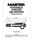
1
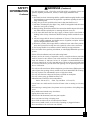
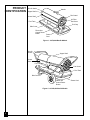
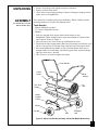
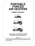
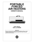
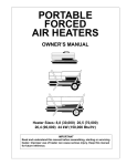
R
PORTABLE
FORCED
AIR HEATERS
OWNER’S MANUAL
Heater Sizes: 30,000 70,000 90,000 150,000 Btu/Hr
Models: BY30CE, BY70CE, BY100CE, and BY150CE
IMPORTANT
Read and understand this manual before assembling, starting or servicing
heater. Improper use of heater can cause serious injury. Keep this manual
for future reference.
CONTENTS
SECTION
PAGE
Safety Information ................................................................................ 2
Product Identification ........................................................................... 4
Unpacking ............................................................................................. 5
Assembly .............................................................................................. 5
Theory of Operation ............................................................................. 6
Fuels ..................................................................................................... 6
Ventilation ............................................................................................ 7
Operation .............................................................................................. 7
Storing, Transporting, or Shipping ....................................................... 8
Preventative Maintenance Schedule ..................................................... 8
Troubleshooting .................................................................................... 9
Service Procedures ............................................................................... 10
Upper Shell Removal .................................................................... 10
Fuel Filter (30/70,000 Btu/Hr Models) ......................................... 11
Fuel Filter (90/150,000 Btu/Hr Models) ....................................... 11
Spark Plug (30,000 Btu/Hr Model) ............................................... 12
Spark Plug (70/90/150,000 Btu/Hr Models) ................................. 13
Air Output, Air Intake, and Lint Filters ......................................... 14
Pump Pressure Adjustment ............................................................ 14
Nozzle (30,000 Btu/Hr Model) ...................................................... 15
Nozzle (70/90/150,000 Btu/Hr Models) ........................................ 16
Pump Rotor .................................................................................... 17
Fan ................................................................................................. 18
Specifications ........................................................................................ 18
Wiring Diagrams .................................................................................. 19
Illustrated Parts Breakdown and Parts List .......................................... 20
30,000 Btu/Hr Model ..................................................................... 20
70,000 Btu/Hr Model ..................................................................... 22
90,000 Btu/Hr Model ..................................................................... 24
150,000 Btu/Hr Model ................................................................... 26
Wheels and Handles (90/150,000 Btu/Hr Models) .............................. 28
Accessories ........................................................................................... 29
EC Conformity Declaration .................................................................. 30
Warranty and Repair Service ................................................................ 32
SAFETY
INFORMATION
WARNINGS
IMPORTANT: Read this Owner’s Manual carefully and completely
before trying to assemble, operate, or service this heater. Improper
use of this heater can cause serious injury or death from burns, fire,
explosion, electrical shock, and carbon monoxide poisoning.
DANGER
Carbon monoxide poisoning may lead to death!
Carbon Monoxide Poisoning: Early signs of carbon monoxide poisoning
resemble the flu, with headaches, dizziness, and/or nausea. If you have these
signs, the heater may not be working properly. Get fresh air at once! Have
heater serviced. Some people are more affected by carbon monoxide than others.
These include pregnant women, persons with heart or lung disease or anemia,
those under the influence of alcohol, and those at high altitudes.
2
Make certain you read and understand all Warnings. Keep this manual for
reference. It is your guide to safe and proper operation of this heater.
Continued
102422
SAFETY
INFORMATION
Continued
WARNINGS (Continued)
• Use only kerosene or No. 1 fuel oil to avoid risk of fire or explosion. Never use
gasoline, naphtha, paint thinners, alcohol, or other highly flammable fuels.
• Fueling
a) Personnel involved with fueling shall be qualified and thoroughly familiar with
the manufacturer's instructions and applicable regulations regarding the safe fueling of heating units.
b) Only the type of fuel specified on the heater's data plate shall be used.
c) All flame, including the pilot light, if any, shall be extinguished and the heater
allowed to cool, prior to fueling.
d) During fueling, all fuel lines and fuel-line connections shall be inspected for leaks.
Any leaks shall be repaired prior to returning the heater to service.
e) At no time shall more than one day's supply of heater fuel be stored inside a
building in the vicinity of the heater. Bulk fuel storage shall be outside the structure.
f) All fuel storage shall be located a minimum of 762cm (25 feet) from heaters,
torches, welding equipment, and similar sources of ignition (exception: the fuel
reservoir integral with the heater unit).
g) Whenever possible, fuel storage shall be confined to areas where floor penetrations do not permit fuel to drip onto or be ignited by a fire at lower elevation.
h) Fuel storage shall be in accordance with the authority having jurisdiction.
• Never use heater where gasoline, paint thinner, or other highly flammable vapors are
present.
• Follow all local ordinances and codes when using heater.
• Heaters used in the vicinity of tarpaulins, canvas, or similar enclosure materials
shall be located a safe distance from such materials. The recommended minimum safe distance is 304.8cm (10 feet). It is further recommended that these
enclosure materials be of a fire retardant nature. These enclosure materials shall
be securely fastened to prevent them from igniting or from upsetting the heater
due to wind action.
• Use only in well-vented areas. Before using heater, provide at least a 2800 square cm
(three-square-foot) opening of fresh, outside air for each 100,000 BTU/Hr of rating.
• Use only in places free of flammable vapors or high dust content.
• Use only the electrical voltage and frequency specified on model plate.
• Use only a three-prong, grounded extension cord.
• Minimum heater clearances from combustibles:
Outlet: 250 cm (8 Ft.) Sides, Top, and Rear: 125 cm (4 Ft.)
• Locate heater on a stable and level surface if heater is hot or running or a fire may
occur.
• When moving or storing heater, keep heater in a level position or fuel spillage may
occur.
• Keep children and animals away from heater.
• Unplug heater when not in use.
• When used with thermostat, heater may start anytime.
• Never use heater in living or sleeping areas.
• Never block air inlet (rear) or air outlet (front) of heater.
• Never move, handle, refuel, or service a hot, operating, or plugged-in heater.
• Never attach duct work to front or rear of heater.
3
102422
PRODUCT
IDENTIFICATION
Hot Air Outlet
Handle
Upper Shell
Fan Guard
Lower Shell
Air Filter
End Cover
Fuel Tank
Fuel Cap
Side Cover
Flame-Out
Control Reset
Button
Power
Cord
Figure 1 - 30/70,000 Btu/Hr Models
Hot Air
Outlet
Upper Shell
Lower
Shell
Fuel Cap
Fan Guard
Fuel Tank
Side Cover
Flame-Out
Control Reset
Button
Power Cord
Figure 2 - 90/150,000 Btu/Hr Models
4
102422
UNPACKING
ASSEMBLY
(For 90,000 and 150,000
Btu/Hr Models Only)
1. Remove all packing items applied to heater for shipment.
2. Remove all items from carton.
3. Check items for any shipping damage. If heater is damaged, promptly inform
dealer where you bought heater.
These models are furnished with wheels and handles. Wheels, handles, and the
mounting hardware are found in the shipping carton.
Tools Needed
• Medium Phillips Screwdriver
• 3/8" Open or Adjustable Wrench
• Hammer
1. Slide axle through wheel support frame. Install wheels on axle.
IMPORTANT: When installing wheels, point extended hub of wheels toward
wheel support frame (see Figure 3).
2. Place cap nuts on axle ends. Gently tap with hammer to secure.
3. Place heater on wheel support frame. Make sure air inlet end (rear) of heater is over
wheels. Line up holes on fuel tank flange with holes on wheel support frame.
4. Place front handle and rear handle on top of fuel tank flange. Insert screws
through handles, fuel tank flange, and wheel support frame. Attach nut finger
tight after each screw is inserted.
5. After all screws are inserted, tighten nuts firmly.
Front Handle
Hot Air
Outlet
Screw
Rear
Handle
Air
Inlet
Fuel Tank
Flange
Wheel
Support
Frame
Wheel
Nut
Cap Nut
Axle
Extended
Hub
Figure 3 - Wheel and Handle Assembly, 90/150,000 Btu/Hr Models Only
5
102422
THEORY OF
OPERATION
The Fuel System: The air pump forces air through the air line. The air is then
pushed through the burner head nozzle. This air causes fuel to lift from the tank. A
fine mist of fuel is sprayed into the combustion chamber.
The Air System: The motor turns the fan. The fan pushes air into and around
the combustion chamber. This air is heated and provides a stream of clean, hot air.
The Ignition System: The electronic ignitor sends voltage to the spark plug.
The spark plug ignites the fuel and air mixture.
The Flame-Out Control System: This system causes the heater to shut down
if the flame goes out.
Motor
Combustion
Chamber
Spark
Plug
Burner
Head
Fan
Air Pump
Intake
Air
Filter
Clean
Heated
Air Out
Cool
Air
In
Output
Air
Filter
Fuel
Tank
Nozzle
Air For Fuel
System
Fuel
Filter
Air line
To Burner
Air For Combustion
And Heating
Electronic
Ignitor
Fuel
Figure 4 - Cross Section Operational View
FUELS
WARNING
Use only kerosene or No. 1 fuel oil to avoid risk of fire or
explosion. Never use gasoline, naphtha, paint thinners,
alcohol or other highly flammable fuels.
Do not use heavy fuels such as No. 2 fuel oil or No. 2 Diesel. Using heavy fuels
will result in:
• clogged fuel filter and nozzle
• carbon build up on spark plug
• use of non-toxic anti-icer in fuel during very cold weather
IMPORTANT: Use a KEROSENE ONLY container. Be sure storage container is
clean. Foreign matter such as rust, dirt, or water will cause the flame-out control to
shut down heater. Foreign matter may also require you to clean fuel system often.
6
102422
VENTILATION
WARNING
Follow the minimum fresh, outside air ventilation
requirements. If proper fresh, outside air ventilation is not
provided, carbon monoxide poisoning can occur. Provide
proper fresh, outside air ventilation before running heater.
Provide a fresh air opening of at least 2800 square cm (three square feet) for each
100,000 BTU/Hr rating. Provide extra fresh air if more heaters are being used.
Example: A 150,000 Btu/Hr heater requires one of the following:
• a two-car garage door raised 15.24 cm (six inches)
• a single-car garage door raised 22.86 cm (nine inches)
• two, 76.20 cm (thirty-inch) windows raised 30.48 cm (twelve inches)
OPERATION
WARNING
Review and understand the warnings in the Safety
Information Section. They are needed to safely operate this
heater. Follow all local codes when using this heater.
To Start Heater
1.
2.
3.
4.
Follow all ventilation and safety information.
Fill fuel tank with kerosene or No. 1 fuel oil.
Attach fuel cap.
Plug power cord of heater into standard 230 volt/50 hertz, grounded (earthed)
outlet. Use an extension cord if needed. Use only a three-prong, grounded
(earthed) extension cord.
Extension Cord Wire Size Requirements
Up to 30.5 meters (100 feet) long, use 1.0 mm2 (16 AWG) conductor
30.6 to 61 meters (101 to 200 feet) long, use 1.5 mm2 (14 AWG) conductor
Heater will start when power cord is plugged into outlet. If not, push in flameout control reset button (see Figures 5 and 6).
Flame-Out Control
Reset Button
Figure 5 - Flame-Out Control Reset
Button, 30/70,000 Btu/Hr
Flame-Out Control
Reset Button
Figure 6 - Flame-Out Control Reset
Button, 90/150,000 Btu/Hr
Continued
102422
7
OPERATION
Continued
To Stop Heater
1. Unplug power cord from outlet.
To Restart Heater
1. Wait 2 minutes after stopping heater.
2. Repeat steps under To Start Heater, page 7.
STORING,
TRANSPORTING,
OR SHIPPING
Note: If shipping, transport companies require fuel tanks to be empty.
1. Drain fuel tank.
Note: Some models have drain plug on underside of fuel tank. If so, remove
drain plug to drain all fuel. If heater does not have drain plug, drain fuel
through fuel cap opening. Be sure all fuel is removed.
2. Replace drain plug if provided.
3. If any debris is noted in old fuel, add 1 or 2 quarts of clean kerosene to tank,
stir, and drain again. This will prevent excess debris from clogging filters
during future use.
4. Replace fuel cap or drain plug. Properly dispose of old and dirty fuel. Check
with local automotive service stations that recycle oil.
5. If storing, store heater in dry place. Make sure storage place is free of dust and
corrosive fumes.
IMPORTANT: Do not store kerosene over summer months for use during next
heating season. Using old fuel could damage heater.
PREVENTATIVE
MAINTENANCE
SCHEDULE
WARNING
Never service heater while it is plugged in, operating, or
hot. Severe burns and electrical shock can occur.
Item
Fuel tank
How Often
Flush every 150-200 hours
of operation or as needed.
How To
See Storing, Transporting, or
Shipping, above.
Air output and
lint filters
Replace every 500 hours of
operation or once a year.
See Air Output, Air Intake,
and Lint Filters, page 14.
Air intake
filter
Wash and dry with soap and
water every 500 hours of
operation or as needed.
See Air Output, Air Intake,
and Lint Filters, page 14.
Fuel filter
Clean twice a heating season
or as needed.
See Fuel Filter, page 11.
Spark plug
Clean and regap every 600
hours operation or replace
as needed.
See Spark Plug, pages 12 and 13.
Fan blades
Clean every season or as needed. See Fan, page 18.
Motor
Not required/permanently
lubricated
8
102422
TROUBLESHOOTING
WARNING
Never service heater while it is plugged in, operating, or hot.
Severe burns and electrical shock can occur.
OBSERVED FAULT
POSSIBLE CAUSE
REMEDY
Heater ignites, but
flame-out control
shuts off heater after
a short period of
time.
Wrong pump pressure
See Pump Pressure
Adjustment, page 14.
Dirty air output, air intake,
and lint filters
Dirty fuel filter
See Air Output, Air Intake
and Lint Filters, page 14.
See Fuel Filter, page 11.
Dirt in nozzle
Dirty photocell lens
See Nozzle, pages 15 and
16.
Clean photocell lens.
Bad flame-out control
Replace flame-out control.
Wrong pump pressure
See Pump Pressure
Adjustment, page 14.
Carbon deposits on spark
plug and/or improper gap
See Spark Plug, pages 12
and 13.
Dirty fuel filter
Dirt in nozzle
See Fuel Filter, page 11.
See Nozzle, pages 15 and
16.
Water in fuel tank
Drain and flush fuel tank
with clean kerosene.
See Storing, Transporting, or Shipping, page 8.
Heater will not
ignite, but motor runs
for a short period of
time.
WARNING: High voltage!
Motor does not start
when heater is
plugged in, fan
rotates slowly or
does not turn.
Electronic ignitor not
grounded (earthed)
Make sure electronic
ignitor mounting is tight.
Bad electronic ignitor
Replace electronic
ignitor.
Flame-out control not reset
Reset flame-out control
button, see Figures 5 and
6, page 7.
Binding pump rotor
If fan is hard to turn, see
Pump Rotor, page 17.
9
102422
SERVICE
PROCEDURES
WARNING
Never service heater while it is plugged in, operating, or
hot. Severe burns and electrical shock can occur.
Upper
Shell
Upper Shell Removal
1. Remove screws and lock
washers along each side of
heater using 5/16" nutdriver. These screws attach
upper and lower shells
together.
2. Lift upper shell off.
3. Remove fan guard.
Fan Guard
Figure 7 - Upper Shell Removal, 30/70,000 Btu/Hr Models
Upper
Shell
Fan
Guard
Figure 8 - Upper Shell Removal, 90/150,000 Btu/Hr Models
10
102422
Fuel Filter
(30/70,000 Btu/Hr Models)
1. Remove side cover screws
using 5/16" nut-driver.
2. Remove side cover.
3. Pull rubber fuel line off
fuel filter neck.
4. Carefully pry bushing and
fuel filter out of fuel tank.
5. Wash fuel filter with clean
fuel and replace in tank.
6. Attach rubber fuel line to
fuel filter neck.
7. Replace side cover.
Fuel Filter
Side Cover
Fuel Line
Figure 9 - Fuel Filter Removal, 30/70,000 Btu/Hr Models
Fuel Filter
Fuel Filter, Bushing,
and Lower Fuel Line
(90/150,000 Btu/Hr Models)
1. Remove side cover screws
using 5/16" nut-driver.
2. Remove side cover.
3. Pull upper fuel line off fuel
filter neck.
4. Carefully pry bushing,
lower fuel line, and fuel
filter out of fuel tank.
5. Wash fuel filter with clean
fuel and replace in tank.
6. Attach upper fuel line to
fuel filter neck.
7. Replace side cover.
Upper
Fuel
Line
Side Cover
Figure 10 - Fuel Filter Removal, 90/150,000 Btu/Hr Models
11
102422
Spark Plug
(30,000 Btu/Hr Model)
1. Remove upper shell (see
page 10).
2. Remove fan (see page 18).
3. Remove fuel and air line
hoses from nozzle
assembly.
4. Remove spark plug wire
from spark plug.
5. Remove two screws using
5/16" nut-driver and
remove burner strap.
6. Place hex-body of spark
plug into vise and tighten.
7. Remove spark plug
mounting nut using 11/16"
open-end wrench.
8. Remove burner strap from
spark plug.
9. Clean and regap spark plug
electrodes to 1.4 mm
(.055") gap.
10. Replace burner strap onto
spark plug. Rotate burner
strap to position spark plug
electrodes (see Figure 13).
11. Tighten spark plug with
spark plug mounting nut.
12. Release hex-body of spark
plug from vise.
13. Replace burner strap onto
combustion chamber.
14. Attach spark plug wire to
spark plug.
15. Attach fuel and air line
hoses to nozzle assembly.
16. Replace fan (see page 18).
17. Replace fan guard and
upper shell.
Combustion
Chamber
Spark Plug
Mounting Nut
Burner
Strap Spark
Plug Spark Plug
Wire
Nozzle
Assembly
Fuel Line
Hose
Air Line
Hose
Figure 11 - Spark Plug Removal, 30,000 Btu/Hr Model
Bend Here
to Adjust
Gap
1.4 mm (.055") Gap
Figure 12 - Spark Plug Gap, 30,000 Btu/Hr Model
Burner
Strap
Burner
Strap
Figure 13 - Spark Plug Rotation, 30,000 Btu/Hr Model Only
12
102422
Spark Plug
Spark Plug
Wire
(70/90/150,000 Btu/Hr Models)
1. Remove upper shell (see
page 10).
2. Remove fan (see page 18).
3. Remove spark plug wire
from spark plug.
4. Remove spark plug from
burner head using 13/16"
open-end wrench.
5. Clean and regap spark plug
electrodes as follows:
Burner
Head
Spark
Plug
70/90,000 Btu/Hr Models:
1.4 mm (.055") gap
150,000 Btu/Hr Model:
2.2 mm (.085") gap
6. Install spark plug in burner
head.
7. Attach spark plug wire to
spark plug.
8. Replace fan (see page 18).
9. Replace fan guard and
upper shell.
Figure 14 - Spark Plug Removal, 70/90/150,000 Btu/Hr Models
Bend Here
to Adjust
Gap
Gap
Figure 15 - Spark Plug Gap, 70/90/150,000 Btu/Hr Models
13
102422
Air Intake Filter
Air Output, Air Intake,
and Lint Filters
Filter End
Cover
1. Remove upper shell (see
page 10).
2. Remove filter end cover
screws using 5/16" nutdriver.
3. Remove filter end cover.
4. Replace air output and lint
filters.
5. Wash or replace air intake
filter (see Preventative
Maintenance Schedule,
page 8).
6. Replace filter end cover.
7. Replace fan guard and
upper shell.
Fan Guard
Lint Filter
Air Output
Filter
Figure 16 - Air Output, Air Intake, and Lint Filters,
30/70,000 Btu/Hr Models
Air Intake Filter
Filter End
Cover
Fan Guard
IMPORTANT: Do not oil filters
Lint Filter
Air Output
Filter
Figure 17 - Air Output, Air Intake, and Lint Filters,
90/150,000 Btu/Hr Models
Pump Pressure
Adjustment
1. Remove pressure gauge
plug from filter end cover.
2. Install accessory pressure
gauge (part number
HA1180).
3. Start heater (see Operation,
page 7). Allow motor to
reach full speed.
4. Adjust pressure. Turn relief
valve to right to increase
pressure. Turn relief valve
to left to decrease pressure.
See specifications at right
for correct pressure for
each model.
5. Remove pressure gauge.
Replace pressure gauge
plug in filter end cover.
(30/70,000 Btu/Hr Models Shown)
Pressure
Gauge
Plug
Relief
Valve
Figure 18 - Pressure Gauge Plug Removal
Model
30,000 Btu/Hr
70,000 Btu/Hr
90,000 Btu/Hr
150,000 Btu/Hr
Pump
Pressure
2.6 PSI
3.8 PSI
4.4 PSI
4.8 PSI
Pressure
Gauge
Figure 19 - Adjusting Pump Pressure
14
102422
Nozzle
Combustion
Chamber
(30,000 Btu/Hr Model)
1. Remove upper shell (see
page 10).
2. Remove fan (see page 18).
3. Remove fuel and air line
hoses from nozzle assembly.
4. Turn nozzle assembly 1/4
turn to left and pull toward
motor to remove.
5. Place plastic hex-body into
vise and lightly tighten.
6. Carefully remove nozzle
from the nozzle adapter
using 5/8" socket wrench.
7. Blow compressed air thru
face of nozzle. This will
free any dirt in nozzle area.
8. Inspect nozzle seal for
damage.
9. Replace nozzle into nozzle
adapter until nozzle seats.
Tighten 1/3 turn more
using 5/8" socket wrench
(4.5-5.1 n-m/40-45 inchpounds).
10. Attach nozzle assembly to
burner strap.
11. Attach fuel and airline
hoses to nozzle assembly.
12. Replace fan (see page 18).
13. Replace fan guard and
upper shell.
Nozzle
Assembly
Fuel Line Hose
Air Line Hose
Figure 20 - Removing Air and Fuel Line Hoses, 30,000 Btu/Hr Model
Burner
Strap
Nozzle
Assembly
Figure 21 - Removing Nozzle Assembly, 30,000 Btu/Hr Model
Nozzle
Face
Nozzle
Seal
Nozzle
Nozzle
Adapter
Air line
Fitting
Fuel line
Fitting
Figure 22 - Nozzle and Nozzle Adapter, 30,000 Btu/Hr Model
15
102422
Nozzle
(70/90/150,000 Btu/Hr Models)
1. Remove upper shell (see
page 10).
2. Remove fan (see page 18).
3. Remove fuel and air line
hoses from burner head.
4. Remove spark plug wire
from spark plug.
5. Remove spark plug from
burner head using 13/16"
open-end wrench.
6. Remove three screws using
5/16" nut-driver and
remove burner head from
combustion chamber.
7. Place burner head into vise
and lightly tighten.
8. Carefully remove nozzle
from burner head using
5/8" socket wrench (see
Figure 24).
9. Blow compressed air thru
face of nozzle. This will
free any dirt in nozzle area.
10. Inspect nozzle seal for
damage.
11. Replace nozzle into burner
head and tighten firmly
(9.1-12.4 n-m/80-110 inchpounds).
12. Attach burner head to
combustion chamber.
13. Install spark plug in burner
head.
14. Attach spark plug wire to
spark plug.
15. Attach fuel and airline
hoses to burner head.
16. Replace fan (see page 18).
17. Replace fan guard and
upper shell.
Combustion
Chamber
Burner Head
Spark Plug
Wire
Screw
Spark
Plug
Air Line Hose
Fuel Line Hose
Figure 23 - Removing Burner Head, 70/90/150,000 Btu/Hr Models
Nozzle
Face
Nozzle
Seal
Nozzle
Burner
Head
Air line
Fitting
Fuel line
Fitting
Figure 24 - Removing Nozzle, 70/90/150,000 Btu/Hr Models
16
102422
Blade
Pump Rotor
Pump
Plate
(Procedure if rotor is binding)
1. Remove upper shell (see
page 10).
2. Remove filter end cover
screws using 5/16" nutdriver.
3. Remove filter end cover
and air filters.
4. Remove pump plate
screws using 5/16" nutdriver.
5. Remove pump plate.
6. Remove rotor, insert, and
blades.
7. Check for debris in pump.
If debris is found, blow
out with compressed air.
8. Install insert and rotor.
9. Check gap on rotor.
Adjust to .076/.101 mm
(.003"/.004") if needed
(see Figure 27).
Filter End
Cover
Fan Guard
Insert
Rotor
Air Output
Filter
Figure 25 - Rotor Location, 30/70,000 Btu/Hr Models
Blade
Pump
Plate
Air Intake
Filter
Filter End
Cover
Fan Guard
Insert
Note: Rotate rotor one
Rotor
full turn to insure the gap is
.076/.101 mm (.003"/.004") at
tightest position. Adjust if
needed.
Air
Output
Filter
10. Install blades, pump plate,
air filters, and filter end
cover.
11. Replace fan guard and
upper shell.
12. Adjust pump pressure (see
page 14).
Figure 26 - Rotor Location, 90/150,000 Btu/Hr Models
Gap Adjusting
Screw
Note: If rotor is still binding,
proceed as follows.
13. Perform steps 1 thru 6
above.
14. Place fine grade sandpaper
(600 grit) on flat surface.
Sand rotor lightly in
“figure 8” motion four
times (see Figure 28).
15. Reinstall insert and rotor.
16. Perform steps 10 thru 12
above.
Air
Intake
Filter
.076/.101 mm (.003"/.004") Gap
Measured With Feeler Gauge
Sandpaper
Rotor
Blade
Gap
Adjusting
Screw
Figure 27 - Gap Adjusting
Screw Locations
Figure 28 - Sanding Rotor
17
102422
Fan
IMPORTANT: Remove fan
from motor shaft before
removing motor from heater.
The weight of the motor
resting on the fan could
damage the fan pitch.
Fan
Setscrew
1. Remove upper shell (see
page 10).
2. Use 1/8" allen wrench to
loosen setscrew which
holds fan to motor shaft.
3. Slip fan off motor shaft.
4. Clean fan using a soft cloth
moistened with kerosene or
solvent.
5. Dry fan thoroughly.
6. Replace fan on motor
shaft. Place fan hub flush
with end of motor shaft
(see Figure 30).
7. Place setscrew on flat of
shaft. Tighten setscrew
firmly (40-50 inch-pounds/
4.5-5.6 n-m).
8. Replace fan guard and
upper shell.
Motor
Shaft
Figure 29 - Fan, Motor Shaft, and Setscrew Location
Fan
Flush
Motor
Shaft
Setscrew
Figure 30 - Fan Cross Section
SPECIFICATIONS
Output Rating (Btu/Hr)
30,000
Fuel
Use Only Kerosene or No. 1 Fuel Oil
Fuel Tank Capacity
(U.S. Gal./Liters)
3.0/11.4
Fuel Consumption
(Gal. Per Hr./Liters Per Hr.) .23/.87
70,000
90,000
150,000
5.0/18.9
9.0/34
13.5/51.1
.49/1.85
.66/2.5
1.1/4.1
Electric Requirements
230 V/50 Hz (Same All Models)
Amperage (Normal Run)
.8
1.0
1.6
1.2
Hot Air Output (CFM/CMM) 140/4
225/6.4
425/12
500/14.2
RPM
2850
2850
2850
1425
18
102422
230V/50Hz
WIRING
DIAGRAMS
Blue
Brown
Green/Yellow
White
White
Motor
Orange Ignitor
Spark Plug
White
Terminal
Board
Red
Green/
Yellow
Red
B
Blue Blue FlameOut
Control
Photocell
R
Reset
Button
Red
Figure 31 - Wiring Diagram, 30/150,000 Btu/Hr Models
230V/50Hz
Blue
White
Motor
Orange Ignitor Spark Plug Terminal
Board
Red
Green/
Yellow
Brown
Green/Yellow
White
White
Red
B
Blue Blue FlameOut
Control
Photocell
R
Reset
Button
Red
Black
S or 2
M or 3
Red
Motor
Start
Relay
L or 1
Figure 32 - Wiring Diagram, 70/90,000 Btu/Hr Models
19
102422
ILLUSTRATED
PARTS
BREAKDOWN
3
43
1
2
30,000 Btu/Hr Model
4
11-5
11-1
5
11-2
6
11
8
7
9
11-4
15
11-3
13
12
13
23
18
16
17
19
24
20
21
22
43
33
34
25
44
27
41
43
31
29
30
37
26
42
28
35
36
18-1
38
18-2
18-3
18-4
18-5
14 10
39
18-6
18-7
18-18
40
18-8
18-17
18-9
18-16
18-10
18-15
18-11
18-14
20
32
Motor and Pump Assembly
18-12
18-13
102422
PARTS LIST
30,000 Btu/Hr Model
KEY
NO.
1
2
3
4
5
6
7
8
9
10
11
11-1
11-2
11-3
11-4
11-5
12
13
14
15
16
17
18
18-1
18-2
18-3
18-4
18-5
18-6
18-7
18-8
18-9
18-10
18-11
18-12
18-13
18-14
18-15
18-16
18-17
18-18
19
20
This list contains replaceable parts used in your heater. When ordering parts, be sure
to provide the correct model and serial numbers (from the model plate), then the part
number and description of the desired part.
PART
NUMBER
PART
DESCRIPTION
M51104-01
098511-54
100647-01
098512-20
M51108-01
M11084-29
M16660
M10908-2
HA3019
M15779-27
**
097124-01
M29835-2
079980-01
M29824
M29681
M11084-26
M30865-02
M50400
M30884
M50631
098138-01
**
098642-02
079975-03
M22009
M22456-2
M29608
M29632
M29633
M29609
M12461-31
M8940
M10993-1
M27694
M22997
M29612-01
M12461-32
M50016
M8643-2
FHPF3-6C
M51105-01
NTC-4C
Handle
Upper Shell
Screw, #10-16 x 1/2"
Combustion Chamber
Heat Shield
Screw, #10-16 x 3/4"
Photocell Bracket
Screw, #6-32 x 3/8"
Photocell Assembly
Power Cord
Burner Strap Assembly
Bracket
Spark Plug
Nozzle Adapter
Nut, 14mm
Nozzle
Screw, #10-16 x 3/8"
Bushing
Strain Relief Bushing
Fan
Rubber Bumper
Motor Bracket
Motor and Pump Assembly
Motor (230V/50Hz)
Pump Body
Insert
Rotor
End Pump Cover
Lint Filter
Intake Filter
End Filter Cover
Screw, #10-32 x 1"
Steel Ball (1/4" Dia.)
Pressure Relief Spring
Adjusting Screw
Plug
Output Filter
Screw, #10-32 x 1 1/8"
Elbow, 90˚ (Barb Fitting)
Blade
Screw, #10-32 x 3/4"
Fan Guard
Hex locknut
QTY.
1
1
6
1
1
2
1
2
1
1
1
1
1
1
1
1
2
2
1
1
2
1
1
1
1
1
1
1
1
1
1
3
1
1
1
1
1
6
1
4
2
1
2
KEY
NO.
21
22
23
24
25
26
27
28
29
30
31
32
33
34
35
36
37
38
39
40
41
42
43
44
PART
NUMBER
PART
DESCRIPTION
M50104-02
M11084-26
098511-12
M11271-8
RF3-5B
M29652-04
M29652-05
M16841-57
M10990-3
M50876-04
Bushing (wires)
Screw, #10-16 x 3/8"
Lower Shell
Clip Nut
Screw, #10-32 x 1/2"
Rubber Airline
Fuel Line
Wire Assembly (red 8 1/2")
Rubber Bushing
Fuel Filter Assembly
(Includes bushing)
098557-07
Electronic Ignitor
M11084-29
Screw, #10-16 x 3/4"
099125-02
Terminal Board
099157-01
Rivet
097630-02
Flame-Out Control
097702-01
Fuel Tank Cap
098513-73
Fuel Tank
M50899-03AA Side Cover
M11084-26
Screw, #10-16 x 3/8"
099177-01
Hex Nut
078918-01
Terminal Board Tab Cap
097785-01
Vinyl Foam Gasket
WLE-3
Lock Washer, #10
NPF-3B
Nut, #10-32
QTY.
1
6
1
6
1
1
1
1
1
1
1
2
1
1
1
1
1
1
2
1
1
1
14
2
PARTS AVAILABLE - NOT SHOWN
HA2210
097649-01
M9900-192
101887-13
101887-14
101639-02
101639-03
Filler Neck Screen
Tradename Decal
Combustion Chamber
Ground Wire
Operation Decal
(English/French)
Operation Decal
(Spanish/Dutch)
Warning Decal
(English/French/Spanish)
Warning Decal
(Dutch)
1
1
1
1
1
1
1
**Not available as an assembly, order parts separately.
21
102422
ILLUSTRATED
PARTS
BREAKDOWN
3
1
45
2
70,000 Btu/Hr Model
4
5
10
7
6
14
8
12
12
11
18
15
16
19
(2)
17
23
24
21
20
Burner Head Assembly
10-1
45
35
36
10-2
10-4
25
22
10-5
27
46
43
26
29
45
10-3
31
28
44
32
10-7
30
39
33
38
37
10-6
34
18-1
40
18-2
18-3
18-4
13
41
18-5
9
18-6
18-7
18-18
18-17
42
18-8
18-9
18-16
18-10
18-15
18-11
18-14
22
Motor and Pump Assembly
18-12
18-13
102422
PARTS LIST
70,000 Btu/Hr Model
KEY
NO.
PART
NUMBER
1
2
3
4
5
6
7
8
9
10
10-1
10-2
10-3
10-4
10-5
10-6
10-7
11
12
13
14
15
16
M51104-01
098511-54
100647-01
098512-12
M11084-29
M16660
M10908-2
HA3019
M15779-27
**
M50880-01
M10659-1
M10809-1
M8882
M51098-02
M50820-01
M10962-2
M11084-27
M30865-02
M50400
097026-01
M50631
M12461-13
17
098138-01
18
18-1
18-2
18-3
18-4
18-5
18-6
18-7
18-8
18-9
18-10
18-11
18-12
18-13
18-14
18-15
18-16
18-17
18-18
19
**
098782-02
079975-02
M22009
M22456-1
M29608
M29632
M29633
M29609
M12461-31
M8940
M10993-1
M27694
M22997
M29612-01
M12461-31
M50016
M8643
FHPF3-5C
M51105-01
This list contains replaceable parts used in your heater. When ordering parts, be sure
to provide the correct model and serial numbers (from the model plate), then the part
number and description of the desired part.
PART
DESCRIPTION
QTY.
Handle
Upper Shell
Screw, #10-16 x 1/2"
Combustion Chamber
Screw, #10-16 x 3/4"
Photocell Bracket
Screw, #6-32 x 3/8"
Photocell Assembly
Power Cord
Burner Head Assembly
Nozzle
Nozzle Seal Washer
Nozzle Seal Spring
Nozzle Seal Sleeve
Burner Head Body
Barb Fitting
Spark Plug
Screw, #10-16 x 1/2"
Bushing
Strain Relief Bushing
Fan
Rubber Bumper
Screw, #8-32 x 1/4"
(holds relay in position)
Motor and Relay
Bracket Assembly
Motor and Pump Assembly
Motor (230V/50Hz)
Pump Body
Insert
Rotor
End Pump Cover
Lint Filter
Intake Filter
End Filter Cover
Screw, #10-32 x 1"
Steel Ball (1/4" Dia.)
Pressure Relief Spring
Adjusting Screw
Plug
Output Filter
Screw, #10-32 x 1"
Elbow, 90˚ (Barb Fitting)
Blade
Screw, #10-32 x 5/8"
Fan Guard
1
1
6
1
2
1
2
1
1
1
1
2
1
1
1
2
1
3
2
1
1
2
2
1
1
1
1
1
1
1
1
1
1
3
1
1
1
1
1
6
1
4
2
1
KEY
NO.
PART
NUMBER
PART
DESCRIPTION
20
21
22
23
24
25
26
27
28
29
30
31
32
NTC-4C
M50104-02
M11084-26
098511-12
M11271-8
098136-02
M16841-58
RF3-5B
M29652-04
079973-01
M16841-57
M10990-3
M50876-05
33
34
35
36
37
38
39
40
41
42
43
44
45
46
098557-07
M11084-29
099125-02
099157-01
097702-01
097630-02
098513-74
M50899-03AA
M11084-26
099177-01
078918-01
097785-01
WLE-3
NPF-3B
Hex locknut
Bushing (wires)
Screw, #10-16 x 3/8"
Lower Shell
Clip Nut
Relay (motor start)
Wire Assembly (red 9 1/2")
Screw, #10-32 x 1/2"
Rubber Airline
Fuel Line
Wire Assembly (red 8 1/2")
Rubber Bushing
Fuel Filter Assembly
(Includes bushing)
Electronic Ignitor
Screw, #10-16 x 3/4"
Terminal Board
Rivet
Fuel Tank Cap
Flame-Out Control
Fuel Tank
Side Cover
Screw, #10-16 x 3/8"
Hex Nut
Terminal Board Tab Cap
Vinyl Foam Gasket
Lock Washer, #10
Nut, #10-32
QTY.
2
1
6
1
6
1
1
1
1
1
1
1
1
1
2
1
1
1
1
1
1
2
1
1
1
14
2
PARTS AVAILABLE - NOT SHOWN
HA2210
097649-01
M9900-192
101887-15
101887-16
101639-02
101639-03
Filler Neck Screen
Tradename Decal
Combustion Chamber
Ground Wire
Operation Decal
(English/French)
Operation Decal
(Spanish/Dutch)
Warning Decal
(English/French/Spanish)
Warning Decal
(Dutch)
1
1
1
1
1
1
1
**Not available as an assembly, order parts separately.
23
102422
2
ILLUSTRATED
PARTS
BREAKDOWN
47
1
90,000 Btu/Hr Model
3
4
5
8
12
13
14
7
15
9
16
(2)
10
8-1
11 17
30
8-2
31
8-4
20
18
8-5
19
25
26
21
28
8-3
32
23
8-7
24
44
8-6
29
47
33
34
36
27
22
47
48
35
37
Burner Head Assembly
38
39
46
45
42
13-1
41
13-2
13-3
13-4
13-5
40
43
6
13-6
13-7
13-18
13-8
13-17
13-16
13-15
13-9
13-10
13-14
13-11
13-13
24
Motor and Pump Assembly
13-12
102422
PARTS LIST
90,000 Btu/Hr Model
This list contains replaceable parts used in your heater. When ordering parts, be sure
to provide the correct model and serial numbers (from the model plate), then the part
number and description of the desired part.
KEY
NO.
PART
NUMBER
PART
DESCRIPTION
1
2
3
4
5
6
7
8
8-1
8-2
8-3
8-4
8-5
8-6
8-7
9
10
11
12
13
13-1
13-2
13-3
13-4
13-5
13-6
13-7
13-8
13-9
13-10
13-11
13-12
13-13
13-14
13-15
13-16
13-17
13-18
14
15
16
17
098511-138
100647-01
098512-07
M16660
HA3019
M27417
M10908-2
**
M23103
M10659-1
M10809-1
M8882
M50924-03
M50820-02
M10962-2
M11084-27
M50814-06
M51345-01
097293-01
**
098783-02
079975-02
FHPF3-5C
M22009
M22456-1
M50545
M12179
M16545
M8940
M10993-1
M27694
M22997
M12461-31
M12244-1
M12461-31
M11637
M50820-02
M8643
M51114-01
M50631
M12461-13
101206-01
18
19
20
098136-04
M16841-59
NTC-4C
Upper Shell
Screw, #10-16 x 1/2"
Combustion Chamber
Photocell Bracket
Photocell Assembly
Drain Plug
Screw, #6-32 x 3/8"
Burner Head Assembly
Nozzle
Nozzle Seal Washer
Nozzle Seal Spring
Nozzle Seal Sleeve
Burner Head Body
Barb Fitting
Spark Plug
Screw, #10-16 x 1/2"
Air Line
Fuel Line
Fan
Motor and Pump Assembly
Motor (230V/50Hz)
Pump Body
Screw, #10-32 x 5/8"
Insert
Rotor
End Pump Cover
Intake Filter
End Filter Cover
Steel Ball (1/4" Dia.)
Pressure Relief Spring
Adjusting Screw
Plug
Screw, #10-32 x 1"
Output Filter
Screw, #10-32 x 1"
Lint Filter
Barb Fitting
Blade
Fan Guard
Rubber Bumper
Screw, #8-32 x 1/4"
Motor and Relay
Bracket Assembly
Relay (motor start)
Wire Assembly (red 13 1/2")
Hex locknut
QTY.
1
8
1
1
1
1
2
1
1
2
1
1
1
2
1
3
1
1
1
1
1
1
2
1
1
1
1
1
1
1
1
1
4
1
6
1
1
4
1
2
2
KEY
NO.
PART
NUMBER
PART
DESCRIPTION
21
22
23
24
25
26
27
28
29
30
31
32
33
34
35
36
37
38
39
40
41
42
43
44
45
46
47
48
098557-07
M11084-29
099125-02
099157-01
M50104-03
M50104-03
M50104-01
099213-01
M11084-27
098511-191
M11271-8
RF3-5B
M51150-01
M10990-3
M51151-01
098513-75
097702-01
M16841-57
097630-02
M50400
M15779-27
M51077-01AA
M11084-27
078918-01
099177-01
097468-01
WLE-3
NPF-3B
Electronic Ignitor
Screw, #10-16 x 3/4"
Terminal Board
Rivet
Bushing
Bushing
Bushing
Button Plug
Screw, #10-16 x 1/2"
Lower Shell
Clip Nut
Screw, #10-32 x 1/2"
Fuel filter
Rubber Bushing
Fuel Line
Fuel Tank
Fuel Tank Cap
Wire Assembly (red 8 1/2")
Flame-Out Control
Strain Relief Bushing
Power Cord
Side Cover
Screw, #10-16 x 1/2"
Terminal Board Tab Cap
Hex Nut
Edge Liner
Lock Washer, #10
Nut, #10-32
QTY.
1
2
1
1
1
1
2
1
6
1
8
1
1
1
1
1
1
1
1
1
1
1
4
1
1
1
16
2
PARTS AVAILABLE - NOT SHOWN
HA2210
097650-01
M9900-192
101888-17
101888-18
101639-04
Filler Neck Screen
Tradename Decal
Combustion Chamber
Ground Wire
Operation Decal
(English/French)
Operation Decal
(Spanish/Dutch)
Warning Decal
1
1
1
1
1
1
1
1
1
2
**Not available as an assembly, order parts separately.
25
102422
2
ILLUSTRATED
PARTS
BREAKDOWN
1
3
150,000 Btu/Hr Model
4
5
8
12
13
14
7
9 15
10
11 17
8-1
30
31
8-2
8-4
19
19
8-5
25
26
21
20
28
8-3
27
23
8-7
29
24
33
34
36
44
8-6
22
32
35
37
Burner Head Assembly
38
39
16
18
42
13-1
13-2
41
13-3
13-4
13-5
40
43
13-6
6
13-7
13-18
13-8
13-17
13-16
13-15
13-9
13-10
13-14
13-11
13-13
26
Motor and Pump Assembly
13-12
102422
PARTS LIST
150,000 Btu/Hr Model
This list contains replaceable parts used in your heater. When ordering parts, be sure
to provide the correct model and serial numbers (from the model plate), then the part
number and description of the desired part.
KEY
NO.
PART
NUMBER
PART
DESCRIPTION
1
2
3
4
5
6
7
8
8-1
8-2
8-3
8-4
8-5
8-6
8-7
9
10
11
12
13
13-1
13-2
13-3
13-4
13-5
13-6
13-7
13-8
13-9
13-10
13-11
13-12
13-13
13-14
13-15
13-16
13-17
13-18
14
15
16
17
18
19
098511-138
100647-01
098512-36
099229-01
HA3019
M27417
M10908-2
**
100735-11
M10659-1
M10809-1
M8882
M50924-08
M50820-02
M10962-2
M11084-27
M50814-06
M51345-01
102042-01
**
102040-01
079975-03
FHPF3-6C
M22009
M22456-2
M50545
M12179
M16545
M8940
M10993-1
M27694
M22997
M12461-31
M12244-1
M12461-32
M11637
M50820-02
M8643-2
M51114-01
M50631
097468-01
101206-01
WLE-3
NPF-3B
Upper Shell
Screw, #10-16 x 1/2"
Combustion Chamber
Photocell Bracket
Photocell Assembly
Drain Plug
Screw, #6-32 x 3/8"
Burner Head Assembly
Nozzle
Nozzle Seal Washer
Nozzle Seal Spring
Nozzle Seal Sleeve
Burner Head Body
Barb Fitting
Spark Plug
Screw, #10-16 x 1/2"
Air Line
Fuel Line
Fan
Motor and Pump Assembly
Motor (with capacitor)
Pump Body
Screw, #10-32 x 3/4"
Insert
Rotor
End Pump Cover
Intake Filter
End Filter Cover
Steel Ball (1/4" Dia.)
Pressure Relief Spring
Adjusting Screw
Plug
Screw, #10-32 x 1"
Output Filter
Screw, #10-32 x 1 1/8"
Lint Filter
Barb Fitting
Blade
Fan Guard
Rubber Bumper
Edge Liner
Motor Bracket
Lock Washer, #10
Nut, #10-32
QTY.
1
8
1
1
1
1
2
1
1
2
1
1
1
2
1
3
1
1
1
1
1
1
2
1
1
1
1
1
1
1
1
1
4
1
6
1
1
4
1
2
1
1
16
2
KEY
NO.
PART
NUMBER
PART
DESCRIPTION
20
21
22
23
24
25
26
27
28
29
30
31
32
33
34
35
36
37
38
39
40
41
42
43
44
45
46
NTC-4C
101901-02
M11084-29
099125-02
099157-01
M50104-03
M50104-03
M50104-01
099213-01
M11084-27
098511-191
M11271-8
RF3-5B
M51150-01
M10990-3
M51151-02
098513-76
097702-01
M16841-57
097630-02
M50400
M15779-27
M51077-01AA
M11084-27
078918-01
099177-01
097785-04
Hex locknut
Electronic Ignitor
Screw, #10-16 x 3/4"
Terminal Board
Rivet
Bushing
Bushing
Bushing
Button Plug
Screw, #10-16 x 1/2"
Lower Shell
Clip Nut
Screw, #10-32 x 1/2"
Fuel filter
Rubber Bushing
Fuel Line
Fuel Tank
Fuel Tank Cap
Wire Assembly (red 8 1/2")
Flame-Out Control
Strain Relief Bushing
Power Cord
Side Cover
Screw, #10-16 x 1/2"
Terminal Board Tab Cap
Hex Nut
Vinyl Foam Gasket
QTY.
2
1
2
1
1
1
1
2
1
6
1
8
1
1
1
1
1
1
1
1
1
1
1
4
1
1
2
PARTS AVAILABLE - NOT SHOWN
HA2210
097650-01
M9900-192
101888-15
101888-16
101639-04
Filler Neck Screen
Tradename Decal
Combustion Chamber
Ground Wire
Operation Decal
(English/French)
Operation Decal
(Spanish/Dutch)
Warning Decal
1
1
1
1
1
1
**Not available as an assembly, order parts separately.
27
102422
WHEELS AND
HANDLES
KEY PART
NO. NUMBER
1
90,000 AND 150,000
Btu/Hr MODELS
HA2203
HA2204
M12345-33
M12342-3
M12831-3
NTC-3C
097896-03
M28526
M51015-01
M16801-2
2
3
4
5
6
7
PART
DESCRIPTION
90,000 150,000
QTY.
QTY.
Handles
Handles
Screw, #10-24 x 1 3/4"
Wheel Support Frame
Wheel Support Frame
Hex Nut, #10-24
Wheel
Cap Nut
Axle
Axle
2
—
8
1
—
8
2
2
1
—
—
2
8
—
1
8
2
2
—
1
1
2
3
5
4
7
6
28
102422
ACCESSORIES
Purchase accessories from
your local dealer.
AIR GAUGE KIT - HA1180
For all models. Special tool to
check pump pressure.
HEAVY DUTY WHEELS AND
HANDLE KIT - HA1202
For heavy duty applications.
Makes your heater even more
portable and convenient.
For 30/70,000 Btu/Hr models.
STANDARD WHEELS AND
HANDLE KIT - HA1206
Makes heater even more portable and
convenient. Easy to assemble.
For 30/70,000 Btu/Hr models.
29
102422
EC CONFORMITY DECLARATION
EC
CONFORMITY
DECLARATION
DESA Europe B.V.
Industrieweg 167, 3044 AS
Postbus 11158
3004 ED Rotterdam
Holland
Manufacturer:
DESA International, Inc.
2701 Industrial Drive
Bowling Green, KY 42101 U.S.A.
Kerosene Portable Forced Air Heaters
Model Numbers: BY30CE, BY70CE, BY100CE, BY150CE
It is declared that these models conform to the Machinery Directive 89/392/EEG,
including 91/368/EEG.
We declare that the models noted are in conformity.
Company
DESA International, Inc.
Name
Title
Douglas D. Rohrer
Vice President, Specialty Products Engineering
07/04/95 — Bowling Green, KY
Date and Place
Signature
30
102422
NOTES
31
102422
WARRANTY AND REPAIR SERVICE
CERTIFICATE OF GENERAL
EQUIPMENT - LIMITED 90 DAY WARRANTY
DESA International warrants new Products sold by it to be
free from defects in material or workmanship for a period of
ninety days after date of delivery to the first user and subject to
the following conditions:
DESA International's obligation and liability under this
Warranty is expressly limited to repairing or replacing at DESA
International's option, any parts which appear to DESA International upon inspection to have been defective in material or
workmanship when shipped from the factory. Such parts shall
be provided at no cost to the user, at the business establishment
of any factory authorized service center or the factory during
regular working hours. The Warranty shall not apply to component parts or accessories of Products not manufactured by
DESA International and which carry the warranty of the manufacturer thereof, or to normal maintenance (such as pressure
adjustments) or to normal maintenance parts (such as filters
and spark plugs). Replacement or repair parts installed in the
Product covered by this Warranty are warranted only for the
remainder of this Warranty as if such parts were original components of said Product. DESA INTERNATIONAL MAKES NO
OTHER EXPRESS WARRANTY. TO THE EXTENT PERMITTED BY LAW DESA INTERNATIONAL MAKES NO IMPLIED
WARRANTY AND MAKES NO WARRANTY OF MERCHANTABILITY OR FITNESS FOR ANY PARTICULAR PUR-
POSE. IN ANY EVENT IMPLIED WARRANTIES INCLUDING
THOSE OF MERCHANTABILITY AND FITNESS FOR A PARTICULAR PURPOSE ARE LIMITED TO THE DURATION OF
THIS EXPRESS WARRANTY.
Any transportation charges, costs of installation, duty,
taxes or any other charges whatsoever must be borne by the
user. DESA International's obligation under this limited Warranty shall not include any liability for direct, indirect, incidental,
or consequential damage or delay. If requested by DESA
International, Products or parts for which a warranty claim is
made are to be returned transportation prepaid by user to the
factory. Any improper use, including operation after discovery
of defective or worn parts, operation beyond capacity, substitution of parts not approved by DESA International, or any
alteration or repair by others in such manner as in DESA
International's judgement affects the Product materially and
adversely, shall void this Warranty.
NO EMPLOYEE OR REPRESENTATIVE IS AUTHORIZED
TO CHANGE THIS WARRANTY IN ANY WAY OR GRANT
ANY OTHER WARRANTY UNLESS SUCH CHANGE IS
MADE IN WRITING AND SIGNED BY AN OFFICER OF DESA
INTERNATIONAL AT ITS HOME OFFICE.
WARRANTY SERVICE
Always specify model and serial numbers when communicating
with the factory.
We reserve the right to amend these specifications at any time
without notice. The only Warranty applicable is our standard
written Warranty. We make no other Warranty, expressed or
implied.
A Service Manual is available by writing to the Technical Service
Department at:
Corporate Headquarters
2701 Industrial Drive
P.O. Box 90004
Bowling Green, Kentucky 42102-9004
U.S.A.
Printed in U.S.A.
102422-01
Rev. B
07/95