1
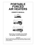
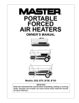
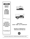
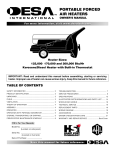
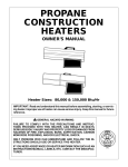
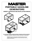
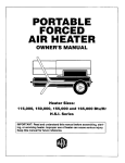
PORTABLE
FORCED
AIR HEATERS
OWNER’S MANUAL
100 SIDE
PV 002
J100ECA 100,000 BTU/Hr
150 SIDE
PV 004
J150ECA 150,000 BTU/Hr
IMPORTANT
Read and understand this manual before assembling, starting or servicing
heater. Improper use of heater can cause serious injury. Keep this manual
for future reference.
CONTENTS
SECTION
PAGE
Safety Information ......................................................................... 3
Product Identification .................................................................... 4
Unpacking ...................................................................................... 5
Assembly ....................................................................................... 5
Theory of Operation ...................................................................... 6
Fuels .............................................................................................. 6
Ventilation ..................................................................................... 7
Operation ....................................................................................... 7
Storage ........................................................................................... 8
Preventative Maintenance Schedule .............................................. 8
Troubleshooting ............................................................................. 9
Service Procedures ........................................................................ 10
Upper Shell Removal .............................................................. 10
Fuel Filter (100,000 BTU/Hr Model) ..................................... 11
Fuel Filter (150,000 BTU/Hr Model) ..................................... 11
Spark Plug ............................................................................... 12
Air Output, Air Intake, and Lint Filters .................................. 13
Pump Pressure Adjustment ..................................................... 13
Nozzle (100,000 BTU/Hr Model) ........................................... 14
Nozzle (150,000 BTU/Hr Model) ........................................... 15
Pump Rotor ............................................................................. 16
Fan ........................................................................................... 17
Wiring Diagram ............................................................................. 18
Specifications ................................................................................. 18
Accessory ...................................................................................... 18
Illustrated Parts Breakdown and Parts List.................................... 19
Wheels and Handles ................................................................ 19
100,000 BTU/Hr Model .......................................................... 20
150,000 BTU/Hr Model .......................................................... 22
Warranty and Repair Service ......................................................... Back Cover
2
SAFETY
INFORMATION
! WARNINGS
IMPORTANT: Read this Owner’s Manual carefully and completely
before trying to assemble, operate, or service this heater. Improper
use of this heater can cause serious injury or death from burns, fire,
explosion, electrical shock, and carbon monoxide poisoning.
! DANGER
Carbon monoxide poisoning may lead to death!
Early signs of carbon monoxide poisoning resemble the flu, with headaches,
dizziness, and/or nausea. If you have these signs, the heater may not be working
properly. Get fresh air at once! Have heater serviced. Some people (such as
pregnant women, persons with heart or lung disease, persons with anemia, those
under the influence of alcohol, and those at high altitudes) are more affected by
carbon monoxide than others.
Make certain you read and understand all Warnings. Keep this manual for
reference. It is your guide to safe and proper operation of this heater.
• Use only kerosene or No. 1 fuel oil to avoid risk of fire or explosion. Never
use gasoline, naphtha, paint thinners, alcohol, or other highly flammable
fuels.
• Never use heater where gasoline, paint thinner, or other highly flammable
vapors are present.
• Follow all local ordinances and codes when using heater.
• Use only in well vented areas. Provide at least three square feet (2800 square
cm) of fresh, outside air for each 100,000 BTU/Hr of rating.
• Use only in places free of flammable vapors or high dust content.
• Use only with the electrical voltage and frequency specified on model plate.
• Use only a three-wire, grounded (earthed) extension cord.
• Minimum heater clearances from combustibles:
Outlet: 8 Ft. (250cm)
Sides, Top, and Rear: 4 Ft. (125cm)
• Locate heater on a stable and level surface while hot or running or a fire may
occur.
• When moving or storing heater, keep heater in a level position or fuel
spillage may occur.
• Keep children and animals away from heater.
• Unplug heater when not in use.
• When used with thermostat, heater may start anytime.
• Never use heater in living or sleeping areas.
• Never block air inlet (rear) or air outlet (front) of heater.
• Never move, handle, refuel, or service a hot, operating, or plugged in heater.
• Never attach duct work to front or rear of heater.
3
PRODUCT
IDENTIFICATION
Hot Air
Outlet
Upper Shell
Lower
Shell
Fuel Cap
Fan Guard
Fuel Tank
Side Cover
Power Cord
Figure 1 - 100,000 BTU/Hr Model
Hot Air
Outlet
Upper Shell
Lower
Shell
Air Filter
End Cover
Fuel Cap
Fan Guard
Fuel
Tank
Power Cord
Figure 2 - 150,000 BTU/Hr Model
4
UNPACKING
ASSEMBLY
1. Remove all packing items applied to heater for shipment.
2. Remove all items from carton.
3. Check items for any shipping damage. If heater is damaged, promptly inform
dealer where you bought heater.
These models are furnished with wheels and handles. Wheels, handles, and the
mounting hardware are found in the shipping carton.
Tools Needed
• Medium Phillips Screwdriver
• 3/8" Open or Adjustable Wrench
• Hammer
1. Slide axle through wheel support frame. Install wheels on axle.
IMPORTANT: When installing wheels, point extended hub of wheels toward
wheel support frame (see Figure 3).
2. Place cap nuts on axle ends. Gently tap with hammer to secure.
3. Place heater on wheel support frame. Make sure air inlet end (rear) of heater is
over wheels. Line up holes on fuel tank flange with holes on wheel support
frame.
4. Place front handle and rear handle on top of fuel tank flange. Insert screws
through handles, fuel tank flange, and wheel support frame. Attach nut finger
tight after each screw is inserted.
5. After all screws are inserted, tighten nuts firmly.
Front
Handle
Hot Air
Outlet
Screw
Rear
Handle
Air
Inlet
Fuel
Tank
Flange
Wheel
Support
Frame
Wheel
Nut
Cap Nut
Axle
ASSEMBLY, EURO
Extended
Hub
PFA/PV 018A
Figure 3 - Wheel and Handle Assembly
5
THEORY OF
OPERATION
The Fuel System: The air pump forces air through the air line. The air is then
pushed through the burner head nozzle. This air causes fuel to lift from the tank. A
fine mist of fuel is sprayed into the combustion chamber.
The Air System: The motor turns the fan. The fan pushes air into and around
the combustion chamber. This air is heated and provides a stream of clean, hot air.
The Ignition System: The electronic ignitor sends voltage to the spark plug.
The spark plug ignites the fuel and air mixture.
Motor
Combustion
Chamber
Spark
Plug
Burner
Head
Fan
Air Pump
Intake
Air
Filter
Clean
Heated
Air Out
Cool
Air
In
Output
Air
Filter
Fuel
Tank
Fuel
Filter
Nozzle
Air For Fuel
System
Air line
To Burner
Air For Combustion
And Heating
THEORY CUTAWAY
Electronic
Ignitor
Fuel
PFA/OV 003
Figure 4 - Cross Section Operational View
FUELS
! WARNING
Use only kerosene or No. 1 fuel oil to avoid risk of fire or
explosion. Never use gasoline, naphtha, paint thinners,
alcohol or other highly flammable fuels.
Do not use heavy fuels such as No. 2 fuel oil or No. 2 Diesel. Using heavy fuels
will result in:
• clogged fuel filter and nozzle
• carbon build up on spark plug
• use of non-toxic anti-icer in fuel during very cold weather
IMPORTANT: Use a KEROSENE ONLY container. Be sure storage container is
clean. Foreign matter such as rust or dirt may require you to clean fuel system
often.
6
VENTILATION
! WARNING
Follow the minimum fresh, outside air ventilation requirements. If proper fresh, outside air ventilation is not provided,
carbon monoxide poisoning can occur. Provide proper
fresh, outside air ventilation before running heater.
Provide a fresh air opening of at least three square feet (2800 square cm) for each
100,000 BTU/Hr rating. Provide extra fresh air if more heaters are being used.
Example: A 150,000 BTU/Hr heater requires one of the following:
• a two-car garage door raised six inches (15.24cm)
• a single-car garage door raised nine inches (22.86cm)
• two, thirty-inch (76.20cm) windows raised twelve inches (30.48cm)
OPERATION
! WARNING
Review and understand the warnings in the Safety
Information Section. They are needed to safely operate this
heater. Follow all local codes when using this heater.
To Start Heater
1. Follow all ventilation and safety information.
2. Fill fuel tank with kerosene or No. 1 fuel oil.
3. Attach fuel cap.
4. Plug power cord of heater into standard 120 volt/60 hertz, grounded (earthed)
outlet. Use an extension cord if needed. Use only a three-wire, grounded
(earthed) extension cord.
Extension Cord Wire Size Requirements
Up to 100 feet (30.5 meters) long, use 16 AWG (1.0mm2) conductor
101 to 200 feet (30.6 to 61 meters) long, use 14 AWG (1.5 mm2) conductor
Heater will start when power cord is plugged into outlet.
To Stop Heater
1. Unplug power cord from outlet.
To Restart Heater
1. Wait 2 minutes after stopping heater.
2. Repeat steps under To Start Heater, above.
7
STORAGE
PREVENTATIVE
MAINTENANCE
SCHEDULE
8
1. Drain fuel tank.
Note: Locate drain plug on underside of fuel tank. Remove drain plug to drain
all fuel. Be sure all fuel is removed.
2. Replace drain plug.
3. Add one gallon (4 liters) of clean kerosene to fuel tank.
4. Attach fuel cap.
5. Move heater forwards and backwards to stir fuel.
6. Remove drain plug and drain fuel tank. Be sure all fuel is removed.
7. Replace drain plug. Properly dispose of old and dirty fuel.
8. Store heater in dry place. Make sure storage place is free of dust and corrosive
fumes.
IMPORTANT: Do not store kerosene over summer months for use during next
heating season. Using old fuel could damage heater.
! WARNING
Never service heater while it is plugged in, operating, or
hot. Severe burns and electrical shock can occur.
Item
How Often
How To
Fuel tank
Flush every 150-200 hours
of operation or as needed.
See Storage above.
Air output and Replace every 500 hours of
lint filters
operation or once a year.
See Air Output, Air Intake,
and Lint Filters, page 13.
Air intake
filter
Wash and dry with soap and
water every 500 hours of
operation or as needed.
See Air Output, Air Intake,
and Lint Filters, page 13.
Fuel filter
Clean twice a heating season
or as needed.
See Fuel Filter, page 11.
Spark plug
Clean and regap every 600
hours operation or replace
as needed.
See Spark Plug, page 12.
Fan blades
Clean every season or
as needed.
See Fan, page 17.
Motor
Not required/permanently lubricated
TROUBLESHOOTING
! WARNING
Never service heater while it is plugged in, operating, or hot.
Severe burns and electrical shock can occur.
OBSERVED FAULT
POSSIBLE CAUSE
REMEDY
Heater burns, but
creates puffs of
smoke.
Heater will not burn
steady.
Heater burns with
odor.
Heater smokes
continuously.
A) Water in fuel
B) Wrong fuel
A) Check fuel tank for
bubbles of water in
bottom. If found, remove
fuel and clean tank (see
Storage, page 8).
B) Remove wrong fuel
and clean tank (see
Storage, page 8). Fill
with correct fuel.
See Pump Pressure
Adjustment, page 13.
See Air Output, Air Intake
and Lint Filters, page 13.
Wrong pump pressure
Dirty air output, air intake,
and lint filters
Dirty fuel filter
Dirt in nozzle
Heater will not
ignite, but motor
runs.
Heater almost out of fuel
Add fuel to tank. See
Fuels, page 6.
Wrong pump pressure
See Pump Pressure
Adjustment, page 13.
Carbon deposits on spark
plug and/or improper gap
Dirty fuel filter
See Spark Plug, page 12.
Dirt in nozzle
Water in fuel tank
See Nozzle, pages 14 and 15.
Drain and flush fuel tank
with clean kerosene. See
Storage, page 8.
!
Motor does not start
when heater is
plugged in, fan
rotates slowly or
does not turn.
See Fuel Filter, page 11.
See Nozzle, pages 14 and 15.
See Fuel Filter, page 11.
WARNING: High voltage!
Electronic ignitor not
grounded (earthed)
Make sure electronic
ignitor mounting is tight.
Bad electronic ignitor
Replace electronic
ignitor.
Binding pump rotor
If fan is hard to turn, see
Pump Rotor, page 16.
Wait two minutes before
trying to restart heater.
Solid state relay not
allowed to reset
9
SERVICE
PROCEDURES
Upper Shell Removal
! WARNING
Never service heater while it is plugged in, operating, or
hot. Severe burns and electrical shock can occur.
Upper Shell
1. Remove screws along each
side of heater using 5/16"
nut-driver. These screws
attach upper and lower
shells together.
2. Lift upper shell off.
3. Remove fan guard.
Fan
Guard
Figure 5 - Upper Shell Removal, 100,000 BTU/Hr Model
Upper Shell
Fan Guard
150 SHELL REMOVAL EA/EB Euro
PFA/P 054
Figure 6 - Upper Shell Removal, 150,000 BTU/Hr Model
10
Fuel Filter
Fuel Filter, Bushing,
and Lower Fuel Line
(100,000 BTU/Hr Model)
Upper
Fuel Line
1. Remove side cover screws
using 5/16" nut-driver.
2. Remove side cover.
3. Pull upper fuel line off fuel
filter neck.
4. Carefully pry bushing,
lower fuel line, and fuel
filter out of fuel tank.
5. Wash fuel filter with clean
fuel and replace in tank.
6. Attach upper fuel line to
fuel filter neck.
7. Replace side cover.
Side Cover
Figure 7 - Fuel Filter Removal, 100,000 BTU/Hr Model
Fuel Filter
(150,000 BTU/Hr Model)
1. Remove upper shell (see
page 10).
2. Remove fan (see page 17).
3. Loosen flare nut using 3/4"
open-end wrench. Push fuel
tube down, away from
burner head. Fuel filter is
located inside of fuel tube.
4. Lift out fuel filter.
5. Wash fuel filter with clean
fuel and replace in fuel
tube.
6. Connect fuel tube to burner
head. Attach flare nut until
nut seats against fuel tube
and fitting. Tighten 1/4 turn
more using 3/4" open-end
wrench (100-130 inchpounds/11.3-14.7 n-m).
7. Replace fan (see page 17).
8. Replace fan guard and
upper shell.
Combustion
Chamber
Fuel Filter
Burner
Head
Fuel Tube
Flare Nut
Figure 8 - Fuel Filter Removal, 150,000 BTU/Hr Model
11
Spark Plug
1. Remove upper shell (see
page 10).
2. Remove fan (see page 17).
3. Remove spark plug wire
from spark plug.
4. Remove spark plug from
burner head using 13/16"
open-end wrench.
5. Clean and regap spark plug
electrodes as follows:
.055" (1.4 mm) = 100,000
BTU/Hr model
.075" (1.9 mm) = 150,000
BTU/Hr model
6. Install spark plug in burner
head.
7. Attach spark plug wire to
spark plug.
8. Replace fan (see page 17).
9. Replace fan guard and
upper shell.
(100,000 BTU/Hr Model Shown)
Spark Plug
Wire
Burner
Head
Spark
Plug
SPARK PLUG REMOVAL 70, 100 &150
Figure 9 - Spark Plug Removal PFA/P 031A
Bend Here
to Adjust
Gap
Figure 10 - Spark Plug Gap
12
Air Output, Air Intake,
and Lint Filters
1. Remove upper shell (see
page 10).
2. Remove filter end cover
screws using 5/16" nutdriver.
3. Remove filter end cover.
4. Replace air output and lint
filters.
5. Wash or replace air intake
filter (see Preventative
Maintenance Schedule,
page 8).
6. Replace filter end cover.
7. Replace fan guard and
upper shell.
IMPORTANT: Do not oil
filters.
Air Intake Filter
Filter End
Cover
Lint Filter
Air Output
Filter
Fan Guard
(100,000 BTU/Hr
Model Shown)
Figure 11 - Air Output, Air Intake, and Lint Filters
(150,000 BTU/Hr Model Shown)
Pump Pressure
Adjustment
1. Remove pressure gauge
plug from filter end cover.
2. Install accessory pressure
gauge (part number
HA1180).
3. Start heater (see Operation,
page 7). Allow motor to
reach full speed.
4. Adjust pressure. Turn relief
valve to right to increase
pressure. Turn relief valve
to left to decrease pressure.
See specifications at right
for correct pressure for
each model.
5. Remove pressure gauge.
Replace pressure gauge
plug in filter end cover.
Relief
Valve
Pressure Gauge Plug
125 PRESSURE ADJUSTMENT Plug
Figure 12 - Pressure Gauge Plug Removal
Model
100,000 BTU/Hr
150,000 BTU/Hr
Pump
Pressure
4.0 PSI
5.0 PSI
Pressure
Gauge
Figure
13PRESSURE
- Adjusting ADJUSTMENT
Pump Pressure
125
13
Nozzle
(100,000 BTU/Hr Model)
1. Remove upper shell (see
page 10).
2. Remove fan (see page 17).
3. Remove fuel and air line
hoses from burner head.
4. Remove spark plug wire
from spark plug.
5. Remove spark plug from
burner head using 13/16"
open-end wrench.
6. Remove three screws using
5/16" nut-driver and
remove burner head from
combustion chamber.
7. Place burner head into vise
and lightly tighten.
8. Carefully remove nozzle
from burner head using
5/8" socket wrench (see
Figure 15).
9. Blow compressed air thru
face of nozzle. This will
free any dirt in nozzle area.
10. Inspect nozzle seal for
damage.
11. Replace nozzle into burner
head and tighten firmly
(80-110 inch-pounds/9.112.4 n-m).
12. Attach burner head to
combustion chamber.
13. Install spark plug in burner
head.
14. Attach spark plug wire to
spark plug.
15. Attach fuel and airline
hoses to burner head.
16. Replace fan (see page 17).
17. Replace fan guard and
upper shell.
Combustion
Chamber
Burner Head
Spark Plug Wire
Screw
Spark
Plug
Air Line Hose
Fuel Line Hose
Figure 14 - Removing Burner Head, 100,000 BTU/Hr Model
Nozzle
Face
Nozzle
Seal
Nozzle
Burner
Head
Air line
Fitting
Fuel line
Fitting
Figure 15 - Removing Nozzle, 100,000 BTU/Hr Model
14
Nozzle
(150,000 BTU/Hr Model)
1. Remove upper shell (see
page 10).
2. Remove fan (see page 17).
3. Remove spark plug wire
from spark plug.
4. Remove spark plug from
burner head using 13/16"
open-end wrench.
5. Loosen flare nut using
3/4" open-end wrench.
Push fuel tube down.
6. Remove air line hose from
burner head.
7. Remove three screws
using 5/16" nut-driver and
remove burner head from
combustion chamber.
8. Place burner head into vise
and lightly tighten.
9. Carefully remove nozzle
from burner head using
5/8" socket wrench (see
Figure 17).
10. Blow compressed air thru
face of nozzle. This will
free any dirt in nozzle area.
11. Inspect nozzle seal for
damage.
12. Replace nozzle into burner
head and tighten firmly
(80-110 inch-pounds/9.112.4 n-m).
13. Attach burner head to
combustion chamber.
14. Install spark plug in burner
head.
15. Attach spark plug wire to
spark plug.
16. Attach fuel tube and airline
hose to burner head.
Attach flare nut until nut
seats against fuel tube and
fitting. Tighten 1/4 turn
more using 3/4" open-end
wrench (100-130 inchpounds/11.3-14.7 n-m).
17. Replace fan (see page 17).
18. Replace fan guard and
upper shell.
Combustion
Chamber
Burner Head
Spark Plug
Wire
Screw
Spark
Plug
Air Line Hose
Flare Nut
Fuel Tube
Figure 16 - Removing Burner Head, 150,000 BTU/Hr Model
Nozzle
Face
Nozzle
Seal
Nozzle
Burner
Head
Figure 17 - Removing Nozzle, 150,000 BTU/Hr Model
15
Pump Rotor
Blade
(Procedure if rotor is binding)
1. Remove upper shell (see
page 10).
2. Remove filter end cover
screws using 5/16" nutdriver.
3. Remove filter end cover
and air filters.
4. Remove pump plate
screws using 5/16" nutdriver.
5. Remove pump plate.
6. Remove rotor, insert, and
blades.
7. Check for debris in pump.
If debris is found, blow
out with compressed air.
8. Install insert and rotor.
9. Check gap on rotor.
Adjust to .003"/.004"
(.076/.101mm) if needed
(see Figure 19).
Air Intake Filter
Filter End Cover
Insert
Rotor
Air Output Filter
150 ROTOR
PFA/P 059
Fan Guard
(100,000 BTU/Hr
Model Shown)
Figure 18 - Rotor Location
Gap Adjusting
Screw
Note: Rotate rotor one
full turn to insure the gap is
.003"/.004" (.076/.101mm) at
tightest position. Adjust if
needed.
10. Install blades, pump plate,
air filters, and filter end
cover.
11. Replace fan guard and
upper shell.
12. Adjust pump pressure (see
page 13).
Note: If rotor is still binding,
proceed as follows.
13. Perform steps 1 thru 6
above.
14. Place fine grade sandpaper
(600 grit) on flat surface.
Sand rotor lightly in
“figure 8” motion four
times (see Figure 20).
15. Reinstall insert and rotor.
16. Perform steps 10 thru 12
above.
16
Pump Plate
.003"/.004"
(.076/.101mm) Gap
Measured With
Feeler Gauge
Sandpaper
Blade
Rotor
Gap Adjusting Screw
Figure 19 - Gap Adjusting
Screw Locations
Figure 20 - Sanding Rotor
Fan
IMPORTANT: Remove fan
from motor shaft before
removing motor from heater.
The weight of the motor
resting on the fan could
damage the fan pitch.
1. Remove upper shell (see
page 10).
2. Use 1/8" Allen wrench to
loosen setscrew which
holds fan to motor shaft.
3. Slip fan off motor shaft.
4. Clean fan using a soft cloth
moistened with kerosene or
solvent.
5. Dry fan thoroughly.
6. Replace fan on motor
shaft. Place fan hub flush
with end of motor shaft
(see Figure 22).
7. Place setscrew on flat of
shaft. Tighten setscrew
firmly (40-50 inch-pounds/
4.5-5.6 n-m).
8. Replace fan guard and
upper shell.
Fan
Setscrew
Motor
Shaft
Figure 21 - Fan, Motor Shaft, and Setscrew Location
Fan
Flush
Motor Shaft
Setscrew
Figure 22 - Fan Cross Section
17
Blue
WIRING
DIAGRAM
White
White
Spark Plug
Terminal
Board
Motor
Ignitor
Red
Black
SPECIFICATIONS
ACCESSORY
Purchase this accessory from
your local dealer.
18
Relay
120V 60Hz
Green/Yellow
Red
Red
Brown
Output Rating (BTU/Hr)
100,000
150,000
Fuel
Use Only Kerosene or No. 1 Fuel Oil
Fuel Tank Capacity
(U.S. Gal./Liters)
9/34
13.5/51
Fuel Consumption
(Gal. Per Hr./Liters Per Hr.) .74/2.8
1.10/4.16
Electric Requirements
120 volt/60 hertz
120 volt/60 hertz
Amperage (Normal Run)
4.5
4.5
Hot Air Output (CFM/CMM)
480/13.6
648/18.3
RPM
3450
3450
AIR GAUGE KIT - HA1180
Special tool to check pump pressure.
WHEELS AND HANDLES
FOR 100,000 AND 150,000 BTU/Hr MODELS
KEY PART
NO. NUMBER
1
HA2203
HA2205
M12345-33
M12342-3
M12831-3
NTC-3C
097896-03
M28526
M51015-01
M16801-2
2
3
4
5
6
7
PART
DESCRIPTION
100,000 150,000
QTY.
QTY.
Handles
Handles
Screw, #10-24 x 1 3/4"
Wheel Support Frame
Wheel Support Frame
Nut Torque, #10-24
Wheel
Cap Nut
Axle
Axle
2
—
8
1
—
8
2
2
1
—
—
2
8
—
1
8
2
2
—
1
1
2
3
5
4
7
6
ASSEMBLY, EURO
PFA/PV 018A
19
2
ILLUSTRATED
PARTS
BREAKDOWN
1
100,000 BTU/Hr Model
3
8
12
13
14
15
16
8-1
9
18
11
17
10
8-2
30
20
31
19
21
25
5
8-3
8-4
27
23
24
8-7
8-5
4
BURNER HEAD 100 EAI/EBI
8-6
PFA/P 022
29
33
36
28
22
32
35
34
37
7
Burner Head Assembly
38
13-1
39
13-2
13-3
26
13-4
13-5
40
6
13-6
13-7
13-18
13-8
13-17
13-9
13-16
13-15
13-10
13-14
13-11
13-13
20
Motor& and
Assembly
MOTOR
PUMP Pump
100 EAI/EBI
PFA/P 010
13-12
PARTS LIST
100,000 BTU/Hr Model
KEY
NO.
1
2
3
4
5
6
7
8
8-1
8-2
8-3
8-4
8-5
8-6
8-7
9
10
11
12
13
13-1
13-2
13-3
13-4
13-5
13-6
13-7
13-8
13-9
13-10
13-11
13-12
13-13
13-14
13-15
13-16
This list contains replaceable parts used in your heater. When ordering parts,
be sure to provide the correct model and serial numbers (from the model plate),
then the part number and description of the desired part.
PART
NUMBER
PART
DESCRIPTION
098511-30
M15823-27
098512-07
078918-01
099213-01
M27417
HA2210
**
M51120-01
M10659-1
M10809-1
M8882
M50924-03
M50820-02
M10962-2
M11084-27
M50814-03
M51345-01
M51153-01
**
079505-02
079975-01
FHPF3-2C
M22009
M22456-1
M50545
M12179
M16545
M8940
M10993-1
M27694
M22997
M12461-31
M12244-1
M12461-31
M11637
Upper Shell
Screw, #10-16 x 1/2"
Combustion Chamber
Tab Cap
Button Plug
Drain Plug
Filler Neck Screen
Burner Head Assembly
Nozzle
Nozzle Seal Washer
Nozzle Seal Spring
Nozzle Seal Sleeve
Burner Head Body
Barb Fitting
Spark Plug
Screw, #10-16 x 1/2"
Air Line
Fuel Line
Fan
Motor and Pump Assembly
Motor
Pump Body
Screw, #10-32 x 1/4"
Insert
Rotor
End Pump Cover
Intake Filter
End Filter Cover
Steel Ball (1/4" Diameter)
Pressure Relief Spring
Adjusting Screw
Plug
Screw, #10-32 x 1"
Output Filter
Screw, #10-32 x 1"
Lint Filter
QTY.
1
8
1
2
1
1
1
1
1
2
1
1
1
2
1
3
1
1
1
1
1
1
2
1
1
1
1
1
1
1
1
1
4
1
6
1
KEY
NO.
PART
NUMBER
PART
DESCRIPTION
13-17
13-18
14
15
16
17
M50820-02
M8643
M51114-01
M50631
M15823-39
098138-02
18
19
20
21
22
23
24
25
26
27
28
29
30
31
32
33
34
35
36
37
38
39
40
097061-01
079010-18
NTC-4C
098557-06
M11084-29
099125-03
099157-01
M30865-02
M11084-27
M50104-02
M30865-02
M11084-27
098511-149
M11271-8
M15823-37
M51150-01
M10990-3
M51151-01
098513-21
097702-01
M51077-01AA
M15779-27
M11143-1
Barb Fitting
Blade
Fan Guard
Rubber Bumper
Screw, #8-18 x 1/2"
Motor and Relay
Bracket Assembly
Relay (Motor Start)
Wire Assembly (Red 14 1/2")
Hex locknut
Electronic Ignitor
Screw, #10-16 x 3/4"
Terminal Board
Rivet
Bushing
Screw, #10-16 x 1/2"
Bushing
Bushing
Screw, #10-16 x 1/2"
Lower Shell
Clip Nut
Screw, #8-18 x 1/4"
Fuel Filter
Rubber Bushing
Fuel Line
Fuel Tank
Fuel Tank Cap
Side Cover
Power Cord
Strain Relief Bushing
QTY.
1
4
1
2
2
1
1
1
2
1
2
1
1
1
4
1
1
6
1
8
1
1
1
1
1
1
1
1
1
PARTS AVAILABLE - NOT SHOWN
099658-02
098234-36
Tradename Decal
General Information Decal
1
1
**Not available as an assembly, order parts separately.
21
ILLUSTRATED
PARTS
BREAKDOWN
2
150,000 BTU/Hr Model
1
3
8
8-1
9
8-2
4
10
7
5
18
19
20
14
8-3
21 11
15
8-4
16
17
40
8-8
8-5
27
28
8-6
8-7
BURNER HEAD 150 EAI/EBI
6
23
13
PFA/P 028
12
22
9
Burner Head Assembly
29
26
32
9
25
24
32
41
30
9
33
31
36
35
37
22-1
39
22-2 22-3
22-4
22-5
22-6
34
22-7
22-18
9
22-8
22-17
38
22-9
22-16
22-15
22-11
22-14
22-13
MOTOR & PUMP 150 EAI/EBI
22
PFA/P 013
Motor and Pump Assembly
22-10
22-12
32
PARTS LIST
150,000 BTU/Hr Model
This list contains replaceable parts used in your heater. When ordering parts,
be sure to provide the correct model and serial numbers (from the model plate),
then the part number and description of the desired part.
KEY
NO.
PART
NUMBER
PART
DESCRIPTION
1
2
3
4
5
6
7
8
8-1
8-2
8-3
8-4
8-5
8-6
8-7
8-8
9
10
11
12
13
14
15
16
17
18
19
20
21
22
22-1
22-2
22-3
22-4
22-5
22-6
098511-50
098068-01
098512-02
M19630
M16790-12
099125-03
M50660-05
**
M18022
M10659-1
M10809-1
M8882
M50924-01
M50820-02
079685-01
M10962-2
M11084-27
M17058
099607-01
099157-01
M11084-27
M50814-03
M50873-01
M12828
M30865-04
NPC-4C
WLM-4
M16661
M51043-01
**
079994-02
079975-01
FHPF3-2C
M22009
M22456-1
M50545
Upper Shell
Heat Deflector
Combustion Chamber
Fuel Filter
Fuel Tube
Terminal Board
Flared 45° Nut
Burner Head Assembly
Nozzle
Nozzle Seal Washer
Nozzle Seal Spring
Nozzle Seal Sleeve
Burner Head Body
Barb Fitting
Male Connector
Spark Plug
Screw, #10-16 x 1/2"
Fan
Terminal Board Bracket
Rivet
Screw, #10-16 x 1/2"
Air Line
Clip
Shell Support Bracket
Open/Closed Bushing
Hex Nut, 1/4-20
Lockwasher, 1/4"
Motor Clamp
Bolt, 1/4-20 x 1 1/2"
Motor and Pump Assembly
Motor
Pump Body
Screw, #10-32 x 1/4"
Insert
Rotor
End Pump Cover
QTY.
1
1
1
1
1
1
1
1
1
2
1
1
1
1
1
1
17
1
1
1
6
1
2
1
1
2
2
4
2
1
1
1
2
1
1
1
KEY
NO.
PART
NUMBER
PART
DESCRIPTION
22-7
22-8
22-9
22-10
22-11
22-12
22-13
22-14
22-15
22-16
22-17
22-18
23
24
25
26
27
28
29
30
31
32
33
34
35
36
37
38
39
40
41
M12179
M16545
M8940
M10993-1
M27694
M22997
M12461-31
M12244-1
M12461-31
M11637
M50820-02
M8643
M16645
M15823-39
097061-01
097060-01
098511-25
M11271-8
M50104-03
M11143-1
M15779-27
M11084-29
M16841-57
098557-06
M10990-3
098513-08
097702-01
M27417
HA2210
078918-01
M50140
Intake Filter
End Filter Cover
Steel Ball (1/4" Diameter)
Pressure Relief Spring
Adjusting Screw
Plug
Screw, #10-32 x 1"
Output Filter
Screw, #10-32 x 1"
Lint Filter
Barb Fitting
Blade
Motor Support Bracket
Screw, #8-18 x 1/2"
Relay-Motor Start
Mounting Bracket
Lower Shell
Nut Clip
Shorty Bushing
Strain Relief Bushing
Power Cord
Screw, #10-16 x 3/4"
Wire Assembly (Red 8 1/2")
Electronic Ignitor
Rubber Bushing
Fuel Tank
Fuel Tank Cap
Drain Plug
Filler Neck Screen
Terminal Board Tab Cap
Fan Guard
QTY.
1
1
1
1
1
1
4
1
6
1
1
4
1
2
1
1
1
7
1
1
1
8
1
1
1
1
1
1
1
2
1
PARTS AVAILABLE - NOT SHOWN
099658-02
098235-16
Tradename Decal
General Information Decal
1
1
**Not available as an assembly, order parts separately.
23
WARRANTY AND REPAIR SERVICE
Contact the Spares and Service Division of:
Ludlow Road, Knighton, Powys LD7 1LP
Telephone: Knighton (0547) 528534 Telex: 35323
Printed in U.S.A.
24
099661-01
Rev. B
8/91