1
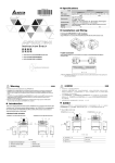
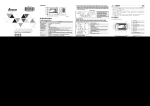
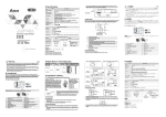
 Specifications
□
Model
□
DVP10EC00 3
Item
Power supply voltage
□
DVP14EC00 3
DVP16EC00 3
100 ~ 240V AC (-15% ~ 10%), 50/60Hz ± 5%
DVP-EC3 starts to run when the power supply rises to 95 ~ 100V AC and stops
when the power supply drops to 70V AC. It continues to run for 10ms after the
power supply is cut off.
2A/250V AC
9VA
Operation
Power supply fuse
Power consumption
DC24V Supply Current
Power supply protection
100mA
DC24V output short circuit protection
1,500V AC (Primary-secondary), 1,500V AC (Primary-PE), 500V AC
(Secondary-PE)
> 5MΩ at 500V DC (between all I/O points and earth)
ESD: 8KV Air Discharge
EFT: Power Line: 2KV, Digital I/O: 1KV, Analog & Communication I/O: 250V
RS: 26MHz ~ 1GHz, 10V/m
The diameter of grounding wire shall not be less than that of L, N terminal of the
power supply. (When many PLCs are in use at the same time, please make sure
every PLC is properly grounded.)
Operation: 0°C ~ 55°C (temperature), 50 ~ 95% (humidity), Pollution degree2
Storage: -25°C ~ 70°C (temperature), 5 ~ 95% (humidity)
International standards: IEC61131-2, IEC 68-2-6 (TEST Fc)/ IEC61131-2 & IEC
68-2-27 (TEST Ea)
Voltage withstand
Insulation resistance
Noise immunity
Earth
Operation/storage
Vibration/shock
resistance
RS-485 communication
mode
Weight (g)
Not supported
Not supported
Supported
R: 192g; T: 180g
R: 202g; T: 185g
R: 212g; T: 190g
1. The input voltage should be 100 ~ 240VAC. The power supply should be connected to L and N terminals.
Please note that wiring AC110V or AC220V to +24V output terminal or digital input points will result in
serious damage on it.
2. Use 1.6mm wire (or longer) for the grounding of it.
3. The power shutdown of less than 10ms will not affect the operation of it. However, power shutdown time
that is too long or the drop of power supply voltage will stop the running of it, and all outputs will go “OFF”.
When the power supply turns normal again, DVP-EC3 will automatically return to its operation. (Please be
aware of the latched auxiliary relays and registers inside DVP-EC3 when programming.)
4. For max. output of the +24V power supply output terminal for each model, please refer to the electrical
specification table. DO NOT connect other external power supplies to this terminal. Every input point
requires 5 ~ 7mA to drive (e.g. 16 input points will require 80 ~ 112mA to drive). The +24V input on DVPEC3 is only for digital input points; other external loads are not suggested.
5V
Digital Input
Input type
DC (SINK or SOURCE)
Input current
產品簡介
感謝您採用台達 DVP-EC3 系列可程式控制器。DVP-EC3 系列目前提供 10 ~ 16 點數的主機。為了確保能夠正確
地安裝及操作可程式邏輯控制器,請在裝機之前,詳細閱讀本使用手冊,並請妥善保存及交由該機器的使用者。
X2
2. 0A
L
產品外觀及各部介紹
電源、運行及錯誤指示燈
輸入點指標
直接固定孔
N
COM 2
通訊口 (R S - 48 5 )
100~240VAC
直流電源輸出
Safety Wiring
+24V 24G S/ S X0 X1 X2 X3 X4 X5 X6 X7 D+ D- SG
CO M2
輸入 / 輸出點指示燈
POWER
RUN
Since DVP-EC3 controls many devices, actions of any device may affect actions of other devices, and the
breakdown of any one device may cause the breakdown of the entire auto-control system and danger.
Therefore, we suggest you wire a protection circuit at the power supply input terminal, as shown in the figure
below.
○
○
○
○
○
○
○
○
24V DC 5mA
On → Off, < 5V DC
Reaction time
(Conversion sampling
time)
X1
DC/DC
Off → On, > 15V DC
Action level
X0
繁體中文
DVP-ES 系列相容,詳細說明請見 DVP-PLC 應用技術手冊【程式篇】,選購之周邊裝置詳細說明請見該產品
隨機使用說明書。
本機為開放型 (OPEN TYPE) 機殼,因此使用者使用本機時,必須將之安裝於具防塵、防潮及免於電擊∕衝
擊意外之外殼配線箱內。另必須具備保護措施(如:特殊之工具或鑰匙才可打開)防止非維護人員操作或意
外衝擊本體,造成危險及損壞。
交流輸入電源不可連接於輸入∕出信號端,否則可能造成嚴重損壞,請在上電之前再次確認電源配線。請勿
在上電時觸摸任何端子。本體上之接地端子 務必正確的接地,可提高產品抗雜訊能力。
+2 4V 24G S/S
Input Point
Input point type
注意事項
本使用說明書提供給使用者電氣規格、功能規格、安裝配線之相關注意事項。其他詳細之程式設計及指令與
Approx. 10ms (0 ~ 20ms adjustable in D1020)
Output Point
ERROR
機種型號
交流電源輸入
8DI-DC / 8DO-R
L
輸出點指標
1
AC power supply load
2
Power supply circuit protection fuse (3A)
3
POWER indicator
4
Emergency stop: This button can cut off the system
power supply when accidental emergency takes place
5
Breaker
6
DVP-EC3 (main processing unit)
7
Earth resistance: < 100Ω
8
Power supply: 100 ~ 240V AC, 50/60Hz
程式通訊口
DVP1 6EC
N
C OM 1
( RS - 2 32 C )
CO M1
C0 Y0 Y1 Y2 Y3 C1 Y4 Y5 Y6 Y7
D IN
D IN
軌固定扣
固定式輸出 / 入端子
尺寸規格
+24V 24G S/S X0
X1
X2 X3
X4
軌槽 ( 3 5 mm )
直接固定孔
X5 X6 X7 D+ D- SG
COM2
IN
0 1 2 3 4 5 6 7
PO WE R
Output point type
Relay-R
Current specification
2A/1 point (5A/COM)
0.5A/1 point (2A/COM)
< 250V AC, 30V DC
5 ~ 30V DC
(UP, ZP must work wit external
auxiliary power supply 24V DC -15%
~ +20%, rated consumption approx.
1mA/point)
Voltage specification
75VA (inductive)
Maximum load
Warning
ENGLISH
wiring. The program design and applicable instructions for DVP-EC3 are the same as those applicable for DVP-ES
series. For detailed information, please refer to “DVP-PLC Application Manual: Programming”. For details of the
optional peripheral, please refer to the instruction sheet enclosed in it.
◎
dust, humidity, electric shock and vibration. The enclosure should prevent non-maintenance staff from operating the
device (e.g. key or specific tools are required for operating the enclosure) in case danger and damage on the device
may occur.
◎
Thank you for choosing Delta DVP-EC3 series programmable logic controller. DVP-EC3 currently offers 10-16
I/O points. To ensure proper installation, operation and maintenance, please read this instruction sheet carefully
and provide users with this instruction sheet before installing DVP-EC3.
C OM 2 C om mun ica tion
p ort (RS- 48 5 )
+24 V24 G S/ S X 0 X 1 X 2 X3 X 4 X5 X 6 X 7
D + D - SG
COM2
D C p ow e r s u pp ly o u tpu t
I/O p oin t in dica to rs
POWE R
R UN
ER ROR
M od el n a me
DVP1 6EC
8DI-DC / 8DO-R
C OM 1 C om mu n ica tion
por t (RS-23 2C)
COM1
A C p ow e r s u pp ly in put
X2
X4
X5
Y1
Y2
Y3
24V D C
X0
X1
X2
X3
X4
X5
Y0
Y1
Y2
UP
ZP
Y3
X3
X4
X5
X6
N
X0
X1
X7
Y0
Y1
Y2
Y3
C1
Y4
X1
X2
+24V 24G S/S X0
D VP14EC 00T3 (8DI-DC / 6DO-T)
X3
X4
X5
X6
X7
UP
ZP
Y0
Y1
Y2
Y3
Y4
+24V
24VDC
Y5
(SOURCE mode)
Y5
X0
X4
X5
X6
X7
D+
D-
SG
X1
Y0
Y1
Y2
Y3
C1
Y4
Y5
Y6
Y7
Below is an example. For detailed point configuration, please refer to specifications of each model:
X1
X2
X3
X4
X5
X6
X7
D+
D-
SG
Y0
Y1
Y2
Y3
Y4
Y5
Y6
Y7
X2
DVP16EC00R3 (8DI-DC / 8DO-R)
+24V 24G S/S
X0
DVP16EC00T3 (8DI-DC / 8DO- R)
UP
ZP
◎ Relay (R) Output Circuit Wiring
○ Flywheel diode: To extend the life span of contact
○ Emergency stop: Uses external switch
Uses 5 ~ 10A fuse at the shared terminal of
○ Fuse:
output contacts to protect the output circuit
○ Varistor: To reduce the interference on AC load
○ Empty terminal: Not in use
○ DC power supply
○ Neon indicator
○ AC power supply
○ Incandescent light (resistive load)
1
1. Use the 12-24 AWG single-core bare wire or the multi-core wire for the I/O wiring, and please use 60/75°C
copper conductor only. The twisting power of the screw for the DVP-EC3 terminal is 3.80 kg-cm (3.30
lb-in) .
2
3
2. DO NOT wire empty terminal. DO NOT place the input signal wire and output power wire in the same
wiring circuit.
4
5
6
C 0 Y0 Y1 Y 2 Y 3 C 1 Y 4 Y 5 Y 6 Y 7
3.2
O utp ut points In d ic a tio n
D IN r ail (35m m)
D ir ec t m ou ntin g ho le
D IN rail c lip
Mounting & Installation
7
Please install PLC in an enclosure with sufficient space around it to allow heat dissipation. For heat
dissipation, make sure to provide a minimum clearance of 50mm between the unit and all sides of the cabinet.
(See the figure.)
8
9
○
F ix ed I/O te r min als
Dimensions
10
◎ Transistor (T) Output Circuit Wiring
Manually exclusive output: Uses external circuit and
forms an interlock, together with DVP-EC3 internal
program, to ensure safety protection in case of any
unexpected errors.
○ DC power supply
○ Emergency stop
○ Circuit protection fuse
The output of the transistor model is “open
If Y0/Y1 is set to pulse output, the output
○ collector”.
current has to be 0.05 ~ 0.5A to ensure normal
1
+24V 24G S/S X0 X1
X2 X3
X4 X5 X6 X7 D+ D- SG
COM2
PO WE R
RUN
E RRO R
IN
0 1 2 3 4 5 6 7
How to screw: Please use M4 screw according to the dimension of the product.
OUT
0 1 2 3 4 5 6 7
How to install DIN rail: PLC can be secured to a cabinet by using the 35mm DIN rail. When mounting PLC to
DIN rail, be sure to use the end bracket to stop any side-to-side movement of it and reduce the change of
wires being loosen. A small retaining clip is at the bottom of it. To secure PLC to DIN rail, place the clip onto
the rail and gently push it up. To remove it, pull the retaining clip down and gently remove it from DIN rail.
99 m m
90m m
DVP16EC
8DI-DC / 8DO-R
COM1
A C 1 00 ~2 4 0V
I NP U T
L
N
C0
Y0 Y1 Y2
Y3 C1 Y4
Y5 Y6 Y7
3.3
9 0.5 m m
95 m m
4 8.5 m m
C0
Y0 Y1 Y2 Y3 C1 Y4
Y5 Y6
Y7
4 8.5 m m
Wiring Notes
Specification & Wiring of Power Supply
The power supply input for DVP-EC3 model is AC input. When operating DVP-EC3, please make sure that:
電氣規格
機種
DVP10EC00□3
DVP14EC00□3
DVP16EC00□3
項目
電源電壓
100 ~ 240V AC (-15% ~ 10%), 50/60Hz ± 5%
當電源緩升至 95 ~ 100V AC 時,DVP-EC3 開始動作,當電源緩降至 70V AC 時,DVP-EC3
動作規格
會停止動作。電源瞬間斷電 10ms 以內繼續運行。
電源保險絲容量 2A/250V AC
消耗電力
9VA
DC24V 供應電流 100mA
電源保護
DC24V 輸出具短路保護
絕緣阻抗
X3
C0
X1
突波電壓耐受量
S/S
X0
DVP16EC00R3/T3
+24V 24G S/S
+5V
24G
DC Signal IN
3. DO NOT drop tiny metallic conductor into DVP-EC3 while screwing and wiring
L
S/ S
DVP14EC00R3/T3
C0
◎
+5 V
+24 V
+24V 24G S/S
N
95 m m
24 G
X3
COM1
A C 1 00 ~2 4 0V
I NP U T
9 0.5 m m
DVP10EC00T3 (6DI- DC / 4DO- T)
Y0
8DI-DC / 8DO-R
L
(SINK mode)
X1
C0
P OW ER , R U N & ER RO R in dic a tors
D ir ec t m oun ting ho le
X0
99 m m
DVP16EC
→ On 30us, On → Off 100us
DVP10EC00R3/T3
Product Profile & Outline
Inpu t po ints Ind ic atio n
Off
OUT
0 1 2 3 4 5 6 7
Input Point Loop Equivalent Circuit & Wiring
DC Signal IN
X2
+24V 24G S/S X0 X1
DVP14EC00R3 (8DI-DC / 6DO-R)
is correctly grounded in order
Introduction
Approx .10ms
D VP 10EC 00R3 (6DI -DC / 4D O-R)
DO NOT connect the input AC power supply to any of the I/O terminals; otherwise serious damage may occur. Check
all the wiring again before switching on the power. Make sure the ground terminal
to prevent electromagnetic interference.
◎
I/O Terminal Layout
+24V 24G S/S
DVP-EC3 series PLC is an OPEN TYPE device and therefore should be installed in an enclosure free of airborne
E RRO R
90m m
The input signal of the input point is the DC power DC input. There are two types of DC type wiring: SINK and
SOURCE, defined as follows:
Installation & Wiring
3.1
RUN
I/O Point Wiring
15W/1 point (Resistive)
90W (resistive)
Reaction time
This instruction sheet provides only information on the electrical specification, general functions, installation and
Transistor-T
2
3
4
雜訊免疫力
接地
操作/儲存環境
耐振動/衝擊
RS-485 通訊模式
重量(約,g)
Manually exclusive output: Uses external circuit and
5
unexpected errors.
5MΩ
以上(所有輸出/入點對地之間 500V DC)
ESD: 8KV Air Discharge
EFT: Power Line: 2KV, Digital I/O: 1KV, Analog & Communication I/O: 250V
RS: 26MHz ~ 1GHz, 10V/m
接地配線之線徑不得小於電源端 L, N 之線徑(多台 PLC 同時使用時,請務必單點接地)
操作:0°C ~ 55°C(溫度),50 ~ 95%(濕度)污染等級 2
儲存:-25°C ~ 70°C (溫度),5 ~ 95%(濕度)
國際標準規範 IEC61131-2, IEC 68-2-6 (TEST Fc)/IEC61131-2 & IEC 68-2-27 (TEST Ea)
不支援
不支援
支援
R:192g;T:180g
R:202g;T:185g
R:212g;T:190g
輸入點電氣規格
輸入點類型
數位輸入
輸入形式
直流(SINK 或 SOURCE)
輸入電流
24VDC,5mA
Off → On,15V DC 以上
動作位準
On → Off,5V DC 以下
反應時間
(轉換取樣時間) 約 10ms(由 D1020 及可作 0 ~ 20ms 的調整)
輸出點電氣規格
輸出點形式
繼電器-R
電晶體-T
電流規格
2A/1 點(5A/COM)
0.5A/1 點(2A/COM)
電壓規格
operation of the model.
an interlock, together with DVP-EC3 internal
○ forms
program, to ensure safety protection in case of any
1,500V AC (Primary-secondary)
1,500V AC (Primary-PE)
500V AC (Secondary-PE)
最大負載
反應時間
250V AC, 30V DC
以下
(電感性)
(電阻性)
約 10ms
75VA
90W
5~30VDC
必須外加輔助電源 24V DC -15% ~ +20%
額定消耗約 1mA/點)
15W/1 點(電阻性)
Off → On 30us,On → Off 100us
(UP, ZP
安裝及配線
3.1
◎
24VDC
直流形式
(DC Signal IN)
SINK 模式
DVP10EC00R3/T3
X2
+24V 24G S/S X0 X1
DVP10EC00R3 (6DI-DC / 4DO-R)
◎
X3
X4
X5
+24V 24G
S/S
X0
X1
X2
X3
X4
X5
Y0
Y1
Y2
项目
电源电压
动作规格
电源保险丝容量
消耗电力
DC24V 供应电流
电源保护
突波电压耐受量
绝缘阻抗
S/S
X0
UP
Y0
Y1
Y2
Y3
X1
X2
X3
X4
X5
X6
X7
ZP
Y3
X1
DVP14EC00R3/T3
+24V 24G S/S
X0
+24V
DVP14EC00R3 (8DI-DC / 6DO-R)
+24V 24G S/S
X0
C0
Y0
X1
X2
直流形式
(DC Signal IN)
SOURCE 模式
Y1
Y2
Y3
C1
Y4
X3
X4
X5
X6
X7
UP
ZP
Y0
Y1
Y2
Y3
Y4
Y5
Y5
X1
X2
X3
X4
X5
X6
X7
D+
D-
SG
DVP14EC00T3 (8DI- DC / 6DO-T)
◎
24VDC
S/S
X0
DVP16EC00R3/T3
+24V 24G S/S
X1
X0
X0
C0
Y0
Y1
Y2
Y3
C1
Y4
Y5
Y6
Y7
X1
X2
X3
X4
X5
X6
X7
D+
D-
SG
○ 突波吸收二極體:可增加接點壽命
○ 緊急停止:使用外部開關
保險絲:使用 5 ~ 10A 的保險絲容量於輸出接點的共用
○ 點,保護輸出點回路。
○ 突波吸收器:可減少交流負載上的雜訊
○ 空端子:不使用
○ 直流電源供給
○ 指示燈:氖燈
○ 交流電源供給
○ 白熾燈(電阻性負載)
DVP16EC00T3 (8DI-DC / 8DO- R)
UP
ZP
Y0
Y1
Y2
Y3
Y4
Y5
Y6
1
Y7
輸出/入配線端請使用 12-24 AWG 單蕊祼線或多蕊線,並請使用 60/75°C 銅導線。DVP-EC3 端子鏍絲扭
力為 3.80 kg-cm (3.30 Ib-in)。
2. 空端子請勿配線。輸入點信號線與輸出點等動力線請勿置於同一線糟內。
3. 鎖螺絲及配線時請避免微小的金屬導體掉入 DVP-EC3 內部。
2
1.
3.2
3
4
盤內安裝
5
6
安裝 PLC 時,請裝配於封閉式之控制箱內,其周圍應保持一定之空間,以確保散熱功能正常(如圖所示)。
7
8
9
互斥輸出:利用外部電路形成互鎖,配合 DVP-EC3 內
○ 部程式,確保任何異常突發狀況發生時,均有安全的保
護措施。
10
直接鎖鏍絲方式:請依產品外型尺寸並使用 M4 鏍絲。
DIN 鋁軌安裝方法:適合 35mm 之 DIN 鋁軌,主機欲掛上鋁軌時,先將 PLC 下方之固定塑膠片壓入,再將
PLC 由上方掛上再往下壓即可。欲取下 PLC 時,主機背面下之固定塑膠片,以一字形起子插入凹槽,向上
撐開即可,該固定機構塑膠片為保持型,因此該固定片撐開後便不會彈回去,當所有的固定片撐開後,再將
主機往上外方取出。
◎ 實用之電晶體輸出回路配線
○ 直流電源供應
○ 緊急停止
○ 電路回路保護用保險絲
2
3
○
電源端規格及配線
1.
2.
3.
4.
○
5
電源輸入為交流輸入,在使用上應注意下列事項:
交流電源輸入電壓 (100 ~ 240V AC),電源請接於 L、N 兩端,如果將 AC110V 或 AC220V 接至+24V 輸出
端或數位輸入點端,將損壞 DVP-EC3,請使用者特別注意。
主機之接地端使用 1.6mm 以上之電線接地。
當停電時間低於 10ms 時,DVP-EC3 不受影響繼續運轉,當停電時間過長或電源電壓下降將使其停止運轉,
輸出全部 Off,當電源恢復正常時,DVP-EC3 亦自動回復運轉。(DVP-EC3 內部具有停電保持的輔助繼電
器及暫存器,使用者在作程式設計規劃時應特別注意使用。)
+24V 電源供應輸出端,各點數機種最大輸出請詳見電氣規格表,請勿將其他的外部電源連接至此端子。每
個輸入點驅動必須 5 ~ 7mA,若以 16 點輸入計算,大約需 80 ~ 112mA,DVP-EC3 系列+24V 輸出僅提供
給數位輸入點使用,不建議應用於其他外部負載。
+24V 24G S/S
5V
X0
X1
注意事項
2.0A
N
由於 DVP-EC3 控制許多裝置,任一裝置的動作可能都會影響其他裝置的動作,因此任一裝置的故障都可能會
造成整個自動控制系統失控,甚至造成危險。所以在電源端輸入回路,建議配置如下的保護回路:
○1 交流電源負載
○2 電源回路保護用保險絲(3A)
○3 電源指示燈
○4 緊急停止:為預防突發狀況發生,設置緊急停
止按鈕,可在狀況發生時,切斷系統電源
○5 斷路器
○6 DVP-EC3 本體
○7 接地阻抗 100Ω 以下
○8 交流電源供應:100 ~ 240VAC, 50/60Hz
◎
电源、运行及错误指示灯
C OM 2 通讯口 RS- 4 85
(
直流电源输出
+ 24V 24 G S / S X 0 X 1 X 2 X 3 X 4 X5 X 6 X 7
输入/输出点指示灯
POWE R
R UN
ER ROR
机种型号
交流电源输入
输出点指标
程序通讯口
DVP1 6EC
8DI-DC / 8DO-R
L
C OM 1
( RS - 232 C )
COM1
N
C 0 Y0 Y 1 Y2 Y 3 C 1 Y4
Y5
DC24V
输出具短路保护
1,500V AC (Primary-secondary); 1,500V AC (Primary-PE); 500V AC (Secondary-PE)
5MΩ
以上(所有输出⁄入点对地之间 500V DC)
+24V 24G S/S
ESD: 8KV Air Discharge
EFT: Power Line: 2KV, Digital I/O: 1KV, Analog & Communication I/O: 250V
RS: 26MHz ~ 1GHz, 10V/m
5V
输出点电气规格
继电器-R
2A/1 点 (5A/COM)
输出点形式
电流规格
电压规格
250V AC, 30V DC
(UP, ZP 必须外加辅助电源
额定消耗约 点)
15W/1 点(电阻性)
Off → On 30us,On → Off 100us
(电感性)
(电阻性)
约 10 ms
最大负载
反应时间
晶体管-T
点 (2A/COM)
0.5A/1
5 ~ 30V DC
24V DC -15% ~ +20%
1mA/
以下
75VA
90W
D IN
轨固定扣
3.1
◎
安全配線回路
X1
輸入∕輸出點之配線
输入点的接入信号为直流电源 DC 输入,DC 型式共有两种接法:SINK 及 SOURCE,其定义如下:
◎ 输入点回路等效电路配线
X2
◎
Y0
轨槽( 35 mm )
+5V
24VDC
X3
X4
X5
Y1
Y2
Y3
+24V 24G
S/S
X0
X1
X2
X3
X4
X5
Y0
Y1
Y2
24G
S/S
X0
D VP 10 EC 00T3 (6DI-DC / 4D O-T)
DVP10EC00R3 (6DI-DC / 4DO-R)
C0
N
由于 DVP-EC3 控制许多装置,任一装置的动作可能都会影响其它装置的动作,因此任一装置的故障都可能会
造成整个自动控制系统失控,甚至造成危险。所以在电源端输入回路,建议配置如下的保护回路:
○1 交流电源负载
○2 电源回路保护用保险丝 (3A)
○3 电源指示灯
○4 紧急停止:为预防突发状况发生,设置紧急停
止按钮,可在状况发生时,切断系统电源
○5 断路器
6
○ DVP PLC 本体
○7 接地阻抗 100Ω 以下
○8 交流电源供应:100 ~ 240V AC, 50/60Hz
直流形式
(DC Signal IN)
SINK 模式
DVP10EC00R3/T3
X0
UP
ZP
Y3
X1
DVP14EC00R3/T3
+24V 24G S/S
X0
X1
X5
X6
C0
Y0
Y1
Y2
Y3
C1
Y4
X1
X2
X2
X3
X3
X4
X4
X5
X6
X7
Y0
Y1
Y2
Y3
Y4
+24V
X7
直流形式
模式
DVP14EC00R3 (8DI-DC / 6DO-R)
X0
Y5
(DC Signal IN)
SOURCE
UP
◎
ZP
X0
X1
X1
X3
X4
X5
X6
X7
D+
D-
SG
Y0
Y1
Y2
Y3
C1
Y4
Y5
Y6
Y7
X2
+24V 24G S/S X0 X1
DVP16EC00T3 (8DI-DC / 8DO-R)
X3
X4
X5
X6
X7
D+
D-
SG
Y0
Y1
Y2
Y3
Y4
Y5
Y6
Y7
C0
)
X2
UP
ZP
以下为举例说明,详细点数配置请见各机种:
◎ 实用之继电器输出回路配线
○ 突波吸收二极管:可增加接点寿命
○ 紧急停止:使用外部开关
保险丝:使用 5 ~ 10A 的保险丝容量于输出接点的共享
○ 点,保护输出点回路。
○ 突波吸收器:可减少交流负载上的噪声
○ 空端子:不使用
○ 直流电源供给
○ 指示灯:氖灯
○ 交流电源供给
○ 白炽灯(电阻性负载)
1
2
輸出/入配線端請使用 12-24 AWG 單蕊祼線或多蕊線,並请使用 60/75°C 铜导线。DVP-EC3 端子鏍絲扭
力為 3.80 kg-cm (3.30 Ib-in)。
2. 空端子请勿配线。输入点信号线与输出点等动力线请勿置于同一线糟内。
3. 锁螺丝及配线时请避免微小的金属导体掉入 DVP-EC3 内部。
3
4
5
盤內安裝
6
安装 PLC 时,请装配于封闭式的控制箱内,其周围应保持一定的空间,以确保散热功能正常(如图所示)。
7
8
9
◎ 实用之晶体管输出回路配线
X1
X2 X3
X4
直接锁镙丝方式:请依产品外型尺寸并使用 M4 镙丝。
DIN 铝轨的安装方法:适合 35mm 的 DIN 铝轨,主机欲挂上铝轨时,先将 PLC 下方的固定塑料片压入,再
将 PLC 由上方挂上再往下压即可。欲取下 PLC 时,主机背面下的固定塑料片,用一字形起子插入凹槽,向
上撑开即可,该固定机构塑料片为保持型,因此该固定片撑开后便不会弹回去,当所有的固定片撑开后,再
将主机往上外方取出。
X5 X6 X7 D+ D- SG
COM2
IN
PO WE R
RUN
E RRO R
0 1 2 3 4 5 6 7
OUT
0 1 2 3 4 5 6 7
99 m m
90m m
8DI-DC / 8DO-R
COM1
A C 1 00 ~2 4 0V
I NP U T
L
N
C0
Y0 Y1 Y2 Y3 C1 Y4
Y5 Y6
Y7
3.3
9 0.5 m m
95 m m
4 8.5 m m
+5V
S/S
X0
Y5
DVP16EC00R3/T3
+24V 24G S/S
24VDC
24G
注意事項
电源端规格及配线
互斥输出:利用外部电路形成互锁,配合 DVP-EC3 内
○ 部程序,确保任何异常突发状况发生时,均有安全的保
护措施。
10
+24V 24G S/S X0
X2
+24V
端子輸入∕輸出配置
+24V 24G S/S
X1
100~240VAC
直接固定孔
固定式输出 /入端子
尺寸規格
L
安裝及配線
X0
DC/DC
2.0A
接地配线的线径不得小于电源端 L, N 之线径(多台 PLC 同时使用时,请务必单点接地)
操作:0°C ~ 55°C(温度),50 ~ 95%(湿度) 污染等级 2
储存:-25°C ~ 70°C (温度),5 ~ 95%(湿度)
国际标准规范 IEC61131-2, IEC 68-2-6 (TEST Fc)/IEC61131-2 & IEC 68-2-27 (TEST
Ea)
不支援
不支援
支援
R:192g;T:180g
R:202g;T:185g
R:212g;T:190g
输入点电气规格
输入点类型
数字输入
输入形式
直流(SINK 或 SOURCE)
输入电流
24V DC 5mA
Off → On,15V DC 以上
动作位准
On → Off,5V DC 以下
反应时间
(转换取样时间) 约 10ms(由 D1020 可作 0 ~ 20ms 的调整)
3.2
Y6 Y7
DVP16EC
輸入點回路等效電路配線
100mA
1.
D + D - SG
COM2
輸入∕輸出點之配線
輸入點之入力信號為直流電源 DC 輸入,DC 型式共有兩種接法:SINK 及 SOURCE,其定義如下:
2A/250V AC
DVP16EC00R3 (8DI-DC / 8DO- R)
输入点指标
直接固定孔
□
DVP16EC00 3
DVP14EC00T3 (8DI- DC / 6DO-T)
產品外觀及各部介紹
D IN
□
DVP14EC00 3
9VA
耐振动/冲击
RS-485 通讯模式
重量(约,g)
產品簡介
安全配線回路
□3
当电源缓升至 95 ~ 100V AC 时,DVP-EC3 开始动作,当电源缓降至 70V AC 时,
DVP-EC3 停止动作。电源瞬间断电 10ms 以内继续运行。
接地
操作/储存环境
+24V 24G S/S
感谢您采用台达 DVP-EC3 系列可编程控制器。DVP-EC3 系列目前提供 10 ~ 16 点数的主机。为了确保能够正确
地安装及操作可编程逻辑控制器,请在装机之前,详细阅读本使用手册,并请妥善保存及交由该机器的使用者。
100~240VAC
简体中文
本使用说明书提供给使用者电气规格、功能规格、安装配线的相关注意事项。其它详细的程序设计及指令与
DVP-ES 系列兼容,详细说明请见 DVP-PLC 应用技术手册【程序篇】,选购的周边装置详细说明请见该产品
随机使用说明书。
本机为开放型 (OPEN TYPE) 机壳,因此使用者使用本机时,必须将其安装于具防尘、防潮及免于电击/
冲击意外的外壳配线箱内。另必须具备保护措施(如:特殊的工具或钥匙才可打开)防止非维护人员操作或
意外冲击本体,造成危险及损坏。
交流输入电源不可连接于输入/出信号端,否则可能造成严重损坏,请在上电之前再次确认电源配线。请勿
在上电时触摸任何端子。本体上的接地端子 务必正确的接地,可提高产品抗噪声能力。
X2
DC/DC
L
因電晶體模組輸出均為開集極輸出 (Open
Collector),若 Y0/Y1 設定為脈波串輸出,為確保電晶
體模組能夠動作正常,其輸出提升電阻,必須維持輸
出電流介於 0.05 ~ 0.5A 之間。
互斥輸出:利用外部電路形成互鎖,配合 DVP-EC3
內部程式,確保任何異常突發狀況發生時,均有安全
的保護措施。
4
注意事項
DVP-EC3
DVP10EC00
1
3.3
1.
100 ~ 240V AC (-15% ~ 10%), 50/60Hz ± 5%
噪声免疫力
以下為舉例說明,詳細點數配置請見各機種:
◎ 實用之繼電器輸出回路配線
DVP16EC00R3 (8DI-DC / 8DO-R)
+24V 24G S/S
+5V
24G
电源输入为交流输入,在使用上应注意下列事项:
交流电源输入电压(100 ~ 240V AC),电源请接于 L、N 两端,如果将 AC110V 或 AC220V 接至+24V 输出
端或数字输入点端,将损坏 DVP-EC3,请使用者特别注意。
2. 主机的接地端使用 1.6mm 以上的电线接地。
3. 当停电时间低于 10ms 时,DVP-EC3 不受影响继续运转,当停电时间过长或电源电压下降将使 DVP-EC3
停止运转,输出全部 Off,当电源恢复正常时,DVP-EC3 亦自动恢复运转。(DVP-EC3 内部具有停电保持
的辅助继电器及寄存器,使用者在作程序设计规划时应特别注意使用。)
4. +24V 电源供应输出端,各点数机种最大输出请详见电气规格表,请勿将其它的外部电源连接至此端子。
每个输入点驱动必须 5 ~ 7mA,若以 16 点输入计算,大约需 80 ~ 112mA,DVP-EC3 系列+24V 输出仅
提供给数字输入点使用,不建议应用于其它外部负载。
DVP-EC3
机种
24G
D VP 10EC 00T3 (6DI-DC / 4D O-T)
C0
電氣規格
+5V
+24V
端子輸入∕輸出配置
○ 直流电源供应
○ 紧急停止
○ 电路回路保护用保险丝
1
2
3
因晶体管模块输出均为开集极输出 (Open Collector),
Y0/Y1 设定为脉冲串输出,为确保晶体管模块能够
○ 若动作正常,其输出提升电阻,必须维持输出电流介于
4
之间。
互斥输出:利用外部电路形成互锁,配合 DVP-EC3 内
护措施。
0.05 ~ 0.5A
○ 部程序,确保任何异常突发状况发生时,均有安全的保
5