1
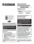
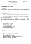
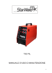
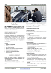
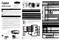
2.2
Product Profile and Outline
FUNCTION SPECIFICATION
3
7
3.1
Function Specification
1-phase Input
10
Item
1 Input
1
High-speed Counter
Module
2
Max. Number of Connecting
Units
8
3
Instruction Sheet
5
7
3
6
This is an OPEN TYPE PLC. The PLC should be kept in an enclosure away from airborne
4. Status Indicator (Power, Run and ERROR)
5. DIN rail clip
6. Terminal
7. Mounting hole
8. Terminal layout
or damage the PLC.
Do NOT connect the AC main circuit power supply to any of the input/output terminals, or it
may damage the PLC. Check all the wiring prior to power up.
2
INTRODUCTION
2.1
Model Name Explanation and Peripherals
1. Power
: Power LED. When external +24V power is applied, it will be ON.
2. L.V.
: Low voltage LED. When external power supply is lower than 19V, it will be ON.
3. UP
: Count up LED
: Count down LED
5. ψA
: When input point A is ON, it will light.
6. ψB
: When input point B is ON, it will light.
module could accept 200KHz pulse from external counter. It uses instruction FROM/TO to
9. YH0, YH1
: When output points YH0 and YH1 are ON, it will light.
1. Please use O-type or Y-type terminals for I/O wiring terminals. The
specification for the terminals is as shown on the left. Tighten PLC
Below 6.2
32-bit mode, can be designated by CR. The controlled registers are written by instruction TO
To suit M3.5 screw terminals
via MPU. When wiring, connect 24V, A24+, B24+, P24+, D24+, A12+, B12+, A5+, B5+, P5+
and D5+ to positive potential. In the same way, 0V, A24-, B24-, P24-, D24-, A12-, B12-, A5-,
terminal screws to a torque of 5 to 8 kg-cm (4.3~6.9 in-lbs).
Input signal source could be 1-phase or 2-phase encoder and voltage level could be 5V, 12V
External Wiring
and 24V. Besides, it also provides two terminals, PRESET and DISABLE. When terminal
PNP output encoder
“count” operation is disabled.
Shielded wire
OUT
A12+
A5+
OA
AB24+
B phase
Shielded wire
OUT
B12+
B5+
OB
Z phase
Nameplate Explanation
B-
Shielded wire
OUT
P+24
P+5
PRESET
Barcode, serial number and version
+24V
Model type
HC: High-speed counter module
4
D+24
2.2K
0.68K
YH0+
2.2K
YH0-
4.7K
HW LW
4.7K
YH1+
0.68K
4.7K
YH1-
4.7K
#0
0.68K
Filter
+24V
0V
#3
+24V
序號 Serial Number
DVP-01HC High-speed Counter Module
CR No.
0.68K
0.5 A 5VDC~30VDC 1~10KHz
01HC- H0T4350001
+5V
0V
External Power
Production place (Taoyuan)
Serial number of version
Production Model
H415E
Content
R
Model type
Count
#1 H 415F ╳ R/W up/down mode
setting
#2 H 4160 ╳ R/W Ring length
Setting Range
System used, read only, DVP-01HC model code=H’0120
Setting range: 0-1, factory setting K0
1-phase 1 input(Software): count up/down mode setting,
count up: K0, count down:K1
16-bit: factory setting is K65,536.
Example:
DC/DC
M0
EH MPU
0V
connection
wire
DTO
+24V
External Power
Count up
DC 12V to 24V
K0
K2
K200
K1
198
199
0
1
1
0
199
198
Count down
Production series
Production week
Production year (2004)
CONTROLLED REGISTER (CR)
4.7K
START
5VDC 12VDC 24VDC 1~200KHz
+24V
for EH series MPU
Shielded wire
1. Operation: 0℃~55℃(Temperature), 50~95%(Humidity), pollution degree 2
2. Storage: -25℃~70℃(Temperature), 5~95% (Humidity)
Standard: IEC1131-2, IEC 68-2-6 (TEST Fc) / IEC1131-2 & IEC 68-2-27 (TEST
Ea)
All places between terminals and ground comply with the spec.
Vibration/Shock
immunity
Antistatic spec.
DIS-
DC5V, 12V, 24V
Product Series
Channel number
DISABLE
24VDC 3W MAX.
Model and Serial Number Explanation
Model
COME
PRE-
D+5
VX.XX
Other Specification
Operation/Storage
4.7K
A24+
A phase
value is equal to the setting, the corresponding output point will activate. The transistors of
output points are independent and isolated.
YH0YH1-
Environmental specifications
01HC High-speed Counter Module
“PRE” is on, the data in CR#10 and CR#11 will be sent to CR#20 and CR#21. That also means
Model Name
Input power supply spec.
Input spec.
Output module spec.
3.2
3. Use copper conductor only, 60℃.
There are two outputs, YH0 and YH1, in hardware input module of DVP-01HC. When counter
5V TO 30VDC, 0.5A
The module number it connects to MPU from closest to the farthest is from 0 to
7. 8 modules is the max and it won’t occupy any digital I/O.
multi-wire cable or conduit.
B5-, P5- and D5- should be connected to negative potential.
current value of counter will be changed to be factory setting. When terminal “DIS” is on,
Output
Connect to DVP-PLC
MPU in Series
2. I/O signal wires or power supply should not run through the same
Below 6.2
t1: rise/fall time≦0.8us
t2: On/Off pulse width≧2.5us
t3: phase difference between A phase and B
phase ≧1us
PRESET input: input pulse width≧50us
DISABLE input: input pulse width≧50us
Output
Form
Range
Output
Signal
Wiring
executing itself after setting CR.
50KHz
There is three count modes: count up/down ((2-phase input for AB phase),
1-phase 2 inputs and 1-phase 1 input.)
Comparison
Method
: PRESET LED. When external terminal PRE is ON, it will light.
100KHz
32-bit mode: -2,147,483648~+2,147,483,647
16-bit mode: 0~65,536 (upper limit can be set by CR#2,3)
Two comparison values are available and correspond to two outputs, YH0 and
YH1, respectively. When count value is equal to settings, the output will be ON. It
adopts hardware circuit comparison and output settings with real-time handle.
YH0+
YH0+: output point YH0, transistor: Collector
YH1+
YH0-: output point YH0, transistor: Emitter
YH1+: output point YH1, transistor: Collector
YH1-: output point YH1, transistor: Emitter
Count
Specification
: DISABLE LED. When external terminal DIS is ON, it will light.
200KHz
A: A Phase
B: B Phase
P: Preset
D: Disable
t3
Count Mode
4. DOWN
2.3
t2
t3
8. DIS
The different counter modes, such as single-phase mode, two phases mode, 16-bit mode or
t2
LED Display
7. PRE
register is 16-bit) in each module. 32 bits data consists of two continuous CRs and allow
200KHz
t1
Waveform
Thank you for choosing DELTA’s PLC DVP series. DVP-01HC high-speed counter input
read/write the data in module via EH MPU. There are 33 Controlled Registers (CR, each
200KHz
t1
9. Extension port to connect extension module/unit 10. RS-485 communication port
dust, humidity, electric shock risk and vibration. Also, it is equipped with protective methods
such as some special tools or keys to open the enclosure, in order to prevent hazard to users
Terminals [A24+], [B24+]: DC24V ±10 %
Terminals P24+], [D24+]: DC12V ~24V ±10 %
Terminals [A12+], [B12+]: DC12V ±10 %
Terminals [A5+], [B5+], [P5+], [D5+]: DC5V ±10 %
Choose only one suitable voltage level for positive
pole of each signal.
Max. Count
Frequency
Input
Signal
Latched
Make sure that power is OFF before wiring.
2. Mounting wire to connect extension module/extension unit
3. Model name
Communication
Address
Please carefully read this instruction thoroughly prior to use the DVP-01HC.
1. DIN rail track (35mm)
Four Times
Frequency
8 units; (All I/O points are not occupied. There can be 8 special extension units at
most connected to EH series.)
Voltage
Level
Unit: mm
WARNING
1
2-phase (A, B) Input
Normal
Double
Frequency
Frequency
DC24V(-15% ~ +20%), Current consumption 140±30mA
Power is supplied from PLC or external power supply.
Power Supply
Attribute
DVP-01HC
9
4
2 Inputs
Make sure the positive/negative pole of 01HC input terminal wiring is correct when using NPN
encoder.
Start-up current for 01HC is IPEAK=0.8A and general working current is IMAX=0.2A(input voltage
is +24V).
Write K200 into first extension module CR#2 and
CR#3 (i.e. CR#3 = 0, CR #2 = 200). Setting
range: K2 to K65,536.
When ring length is set to K200, The count value
will be as shown on the left.
Count up: when count value reaches 199, the
next count value will be 0.
Count down: when count value reaches 0, the
next count value will be 199.
Setting notices:
1. It must write with 32-bit.
2. It only can be write-in when writing value is greater or equal to current count value.
3. It only can be set when counter stops counting and count mode is 16-bit.
#4
H4162 ╳ R/W
instruction
Instruction, factory setting: K0
CR#4
b0
‘0’(Off)
‘1’ (On)
Count is disabled
Count is enabled
YH0 output is
b1
YH0 output is enabled
disabled
YH1 output is
b2
YH1output is enabled
disabled
YH0 and YH1 affect
YH0 and YH1
each other (they
b3
activate
cannot be ON/OFF
independently
simultaneously)
b4
Preset disabled
Preset is enabled
b5~b7
Reserved
b8
Not used
Clear error flag
b9
Not used
Clear YH0 output
b10
Not used
Clear YH1 output
b11
Not used
YH0 output setting
b12
Not used
YH1 output setting
b13~b15
Reserved
1. When b0 is set to 1 and terminal “DIS” is off, count
is enabled.
2. When b1 is set to 1, YH0 (hardware comparison
output) output is enabled.
3. When b2 is set to 1, YH1 (hardware comparison
output) output is enabled.
4. When b3 is set to 1, YH0 and YH1 affect each
other (they cannot be ON/OFF simultaneously). In
other words, when YH0=ON, YH1 must be OFF
and when YH0=OFF, YH1 must be ON. When
b3=0, YH0 and YH1 activate independently.
5. When b4=0, terminal “PRE” is disabled.
6. When b8=1, all error flags (CR#29) will be cleared.
7. When b9=1, YH0 output will be cleared to be OFF.
8. When b10=1, YH1 output will be cleared to be
OFF.
9. When b11=1, YH0 output will be ON.
10.When b12=1, YH1 output will be ON.
Setting notes:
1. After setting CR#4, b8~b12 will be cleared to 0.
2. It needs to set to disable count(b0=0) before setting count mode (CR#5).
When current value of counter = comparison value, output
YH0/YH1 will be ON and hold. User can clear output point by
using b9 and b10 of CR#4.
If count value = comparison value by using PRESET or
instruction TO, corresponding output YH0 or YH1 will be OFF. In
other case that count value = comparison value does not use
PRESET or instruction TO, corresponding output YH0 or YH1 will
be ON.
#16~ #19
32 bits
K0
K2
K4
K6
2-phase 2 inputs
Normal frequency
Double frequency
Four times frequency
1-phase 2 inputs
1-phase 1 input
YH0
16 bits
K1
K3
K5
K7
Count mode
32 bits
16 bits
K8
K9
K10
K11
#27 H4179 ○
CR#27
b0
b1
b2
b3
Note1: count up/down control is controlled by external input control.
Note2: count up/down control is controlled by internal control register(CR#1).
b5
0
b6
upper limit
+2,147,483,647
When it is 32-bit mode, the count range is -2,147,483,648 2,147,483,647. When overflow event is occurred, count value will
be changed from upper limit to lower limit or from lower limit to
upper limit. And upper limit is +2,147,483,647 and lower limit is
-2,147,483,648.
b7~ b15
Internal controlled register count
up/down control
K0
CR#1
A input
On (count down )
count up
count down
pulse of count down
B input
1
2
2
#6 ~ #9
1
count value
1
2
3
3
3
2
1
0
2.
0
#15 #14 H416C ╳ R/W
Four times frequency (K4, K5)
A input
A input
B input
B input
count value
0 1
2 3 4
3 2 1 0
count value
YH0 comparison
value
YH1 comparison
value
3.
01 2 3 4 5 67
76 5 4 3 21
YH1
b5
b4
CR#27
b4
b5
b6
b7
‘0’(Off)
PRE input is Off
DIS input is Off
YH0 output is Off
YH1 output is Off
System version
Communication
address
Baud Rate
Setting
applied to HC at this time or power is applied after EH MPU completing detecting extension
module, the connection will fail. Therefore, power wiring and power supply timing should be
as following.
Function code: 03H: read register data. 06H: write one WORD data into register. 10H: write
Power supply
85~264VAC
AC/DC
L N G
2. Open extension port of EH MPU and connect to HC extension unit with cable. There is no
connection order for EH MPU to connect extension unit, mix connection is allowed.
the circuit between YH0+, YH0- and YH1+, YH1-. There is a Zener Diode that is connected
between YH0+, YH0- and YH1+, YH1- in HC. If the positive/negative pole is wrong, it may
AC power input
0V
t1:1~2 seconds
+24V_INT
01HC
t1
+24V_EXT
+24V 24G
t2:1~3 seconds
t2
+24V_INT
Timing analysis
When power supply for HC is +24V_INT:
t5>t3, power is ON and the connection of HC
extension unit is normal.
When power supply for HC is +24V_EXT:
Because start time (t2) of external power supply
for HC extension module is unknown, user must
make sure that t2+t4 < t1+t5, otherwise HC
extension module cannot be detected by MPU.
complete initialling HC
(supply from +24_INT)
t3:0.5~1 seconds
t3
complete initialling HC
(supply from +24_EXT)
t4:0.5~1 seconds
t4
MPU starts to detect
extension unit
t5:2 seconds
t5
7. The maximum special extension modules number for EH MPU connects is 8 special
extension modules. After power is ON, EH will save module codes of connected special
modules in D1320~D1327 in order. The module code of 01HC is H’0120. It indicates
communication is OK when H’0120 is displayed in the corresponding special D register by
using HPP02 or other monitor software.
Troubleshooting
Judge the errors by the indicators on the front panel. When errors occurred on DVP PLC,
please check:
☼ “POWER” LED
The “POWER” LED at the front of HC extension module will be lit (in green) if the power
is on. If the indicator is not on when power up, please remove the wiring on terminals
+24V. Once the indicator lights after this, it means that the 24V DC power supply of the
PLC is overloaded.
Please do not use the DC power supply from the +24V terminals,
but use a DC24V power supply instead.
☼ L.V. LED
The “L.V.” LED at the front of HC extension module will be lit if input voltage is not
enough. The extension module won’t active at this time.
6
RELATIVE INSTRUCTIONS
API
78
D
FROM
Program
Example
Read Special Module CR Data
P
: number of special module (m1=0~7).
read.
: address for saving reading data.
Instruction
Explanation
: CR number of special module that will be
: data number for reading once.
Writing special module #0 of CR#24 into D0 and special module #0 of CR#25 into D1. only
write two data once (n=2).
X10
FROM
API
79
D
Instruction
Explanation
3. The power supply of HC extension unit must be external +24VDC power supply.
4. Before power up, check if the load circuit of output points YH0 and YH1 is correct, especially
+24V
EH MPU
TRIAL RUN & TROUBLESHOOTING
1. Make sure that the power of MPU and extension unit is OFF before wiring.
+24V_EXT
+24V input
Hexadecimal, display current software version, such as version
1.0A will be displayed as H’010A.
RS-485 communication address, range set: 01~255, factory
default value: K1
Baud rate setting: 4800,9600,19200bps,38400 bps,57600 bps,
115200 bps. ASCII mode data format is always 7Bit, even bit,
and 1 stop bit (7 E 1). RTU mode data format is always 8Bit,
even bit , and 1 stop bit ( 8 E 1)
b0: 4800 bps(bit/sec.), b1: 9600 bps(bit/sec.) (default value)
b2: 19200 bps(bit/sec.), b3: 38400 bps(bit/sec.)
b 4: 57600 bps(bit/sec.), b 5: 115200 bps(bit/sec.)
b6~b14: reserved, b15: ASCII / RTU mode switch
Communication protocol can be Modbus ASCII mode and RTU mode. For ASCII mode, data
Power supply timing
Power wiring
Data register that is used to save all error status. Refer to
table below.
Baud rate could be 4800, 9600, 19200, 38400 and 57600bps.
cause unexpected result.
YH1-
6. After power up MPU, it will start to detect extension module. If no external +24VDC power is
‘1’(On)
PRE input is On
DIS input is On
YH0 output is On
YH1 output is On
MPU connects to HC extension module
Factory setting for counter (#10: Lower word / #11: Upper word),
factory setting: K0
Setting notes: in 16-bit mode, CR#11 will be cleared to 0 when
writing factory setting.
YH0 output comparison value (#12: Lower word / #13: Upper
word), factory setting: K32,767.
Setting notes: in 16-bit mode, CR#13 will be cleared to 0 when
writing YH0 comparison value.
YH1 output comparison value (#14: Lower word / #15: Upper
word), (factory setting: K32,767).
Setting notes: in 16-bit mode, CR#15 will be cleared to 0 when
writing YH1 comparison value.
YH0-
YH1-
damage internal circuit.
The indication of count up/down and terminal status
‘1’(On)
Count up
Count down
A input is on
B input is on
5
DC 5~24VDC
5. Before power up, check if A phase or B phase connects to correct voltage level. (there are
‘1’(On)
Setting value > current
value
Setting value = current
value
Setting value < current
value
multiple WORDs into register.
Reserved
#11 #10 H4168 ╳ R/W Factory setting
#13 #12 H416A ╳ R/W
b6
‘0’(Off)
Setting value≦
current value
Setting value≠
current value
Setting value≧
current value
(8 E 1).
A input
0
Action status
CR#26
format is 7Bits, even, 1 stop bit (7 E 1). For RTU mode, data format is 8Bits, even, 1 stop bit
Double frequency (K2, K3)
YH0-
b9, b10 SET
using RS-485.
1.
2-phase 2 inputs (K0~K5)
Normal frequency (K0, K1)
count value
current value
of counter CR#4
CR#0~CR#34: The corresponding addresses are H 415E-H 4180 for user to read/write by
pulse of count up
count
value
count
value
‘1’(On)
Setting value >
current value
Setting value =
current value
Setting value <
current value
1-phase 2 inputs (K6~K7)
1-phase 2 inputs counter (K6, K7)
B input
count up
count down
#32 H417E ○ R/W
K1
A input
R
load
DC 5~24VDC
Reserved
CR number that is designated by instruction FROM/TO exceeds the usage range
Overflow indication, When count-up value exceeds upper limit(upper limit is CR#2 and #3
in 16-bit mode and it is K2,147,483,647 in 32-bit mode)
Overflow indication, When count-down value is less than lower limit(lower limit is 0 in
16-bit mode and it is K-2,147,483,648 in 32-bit mode)
Reserved
#31 H417D ○ R/W
-2,147,483,648
lower limit
A input
Off ( count up )
B input
b9, b10 SET
YH0+ YH1+
Comparison
value
Error Status
#30 H417C ○
Setting notes:
1. It only can be written when count is disabled (bit 0 of CR#4 is 0).
2. After writing, it will initial controlled registers as follows: CR#1: 0. CR#2, 3: 65,536. CR#10: 0. CR#12, 13:
32,767. CR#14, 15: 32,767. CR#20, 21: 0. CR#22, 23: 0. CR#24, 25: 0.
1-phase 1 input (K8~K11)
External input count up/down control
(K8~K9)
R
‘0’(Off)
A input is off
B input is off
CR#29
b0~ b3
b4
count length
CR#3, #2
32-bit mode
current value
of counterCR#4
Load
three voltage level: +24, +12V and +5V) If +24V signal connects to +5V input terminal, it may
#29 H417B ╳ R/W Error status
16-bit mode
When it is 16-bit mode, the count values are all positive value and its
range is 0~65,536. When overflow event is occurred, count value will
be changed from upper limit to 0 or from 0 to upper limit. The upper
limit is set by CR#3 and CR #2.
b1
b0
CR#5 settings
Count Up/Down is controlled
by Hardware (Note 1)
Count Up/Down is controlled
by software (Note 2)
‘0’(Off)
Setting value≦
current value
Setting value≠
current value
Setting value≧
current value
b2
CR#5 settings
Comparison
value
YH0+ YH1+
Current value of counter (#20: Lower word / #21: Upper word),
factory setting is K0.
Setting notes:
Current value of
it must write with 32-bit.
#21 #20 H4172 ╳ R/W
counter
In 16-bit mode, value that is written must be less than ring
length (CR#2).
In 16-bit mode, CR#21 will be cleared to 0 when writing into
current value of counter.
Max. count value (#22: Lower word / #23: Upper word), factory
#23 #22 H4174 ╳ R/W Max. count value
setting is K0.
Min. count value (#24: Lower word / #25: Upper word), factory
#25 #24 H4176 ╳ R/W Min. count value
setting is K0.
#26 H4178 ╳ R Comparison result Comparison result
Count mode K0~K11, factory setting is K0
Count mode
current value
of counter
Reserved
CR#26
#5 H4163 ╳ R/W Count mode setting
current value
of counter
Program
Example
TO
K0
K24
D0
K2
Special Module CR Data Write In
P
: number of special module (m1=0~7).
: CR number of special module that will be
wrote in.
: data to write in CR.
: data number to write in once.
Using 32-bit instruction DTO to write D11 and D10 into special module#0 of CR#3 and CR#2.
only write a data once (n=1).
X11
DTO
K0
K2
D10
K1