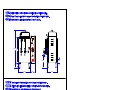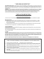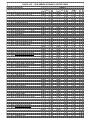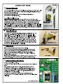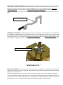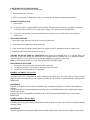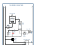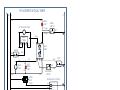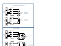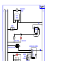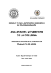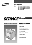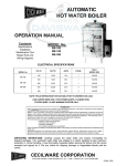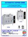
1
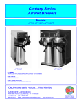
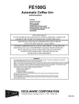
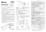
ELECTRICAL SPECIFICATIONS
Amps
Kilowatts
3
1
Heater
Heater 1 Phase 3 Phase
Phase Element Phase Element (3) wire (4) wire
Model No.
Volts
FE75-N
CL75-N
CH75-N
120/240
7
G031A (1)
6
G024A (1)
29
15
120/208
5.3
G031A (1)
4.5
G024A (1)
26
12
120/240
8
G013A (1)
8
G026A (1)
34
20
120/208
6
G013A (1)
6
G026A (1)
29
17
120/240
7
G031A (1)
8
G026A (1)
29
20
120/208
5.3
G031A (1)
6
G026A (1)
26
17
220
6.7
G013A (1)
-
-
31
-
120/240
10
G011A (2)
10
G018A (2)
42
24
120/208
7.5
G031A (1)
7.5
G018A (2)
38
22
120/240
-
-
15
G011A (3)
-
37
120/208
-
-
11.3
G011A (3)
-
33
FE100-N
CH100-N
CL100-N
CL100-N EXPORT
FE200-N
CL200-N
FE300-N
Export Voltages: 220V, 380V, 440V are available.
RECOMMENDED WIRE SIZE FOR FIELD-WIRING URNS
Model No.
Wire Size
3 Phase
1 Phase
FE75-N CL75-N CH75-N CL100-N
(2) 10 AWG + GND
(3) 10 AWG + GND
CL100-N EXPORT
(2) 10 AWG + GND
-
FE100-N CH100-N
(2) 8 AWG + GND
(3) 10 AWG + GND
FE200-N CL200-N
(2) 6 AWG + GND
(3) 8 AWG + GND
-
(3) 8 AWG + GND
FE300-N
Neutral and Ground Wires # 14 AWG min.
Note: Field wiring must be suitable for 75° C. Use copper wire only for power supply connections.
GROUNDING: ON ALL URNS, CONNECT A GROUND WIRE TO GROUNDING LUG TO COMPLY WITH
LOCAL ELECTRICAL CODES (14 AWG MIN. 75° C)
WARNING LABEL NN85A
NN85A
POWER
STOP
BREW
29.1 19.3
BLEND
9
8
OF
F
10
7
6
1
5
4
3
2
CAUTION
HOT SURFACES
3.5
2.5
10.1
NN10A
4.0
16.0
5.4
14.0
POWER
STOP
BREW
BLEND
29.1
19.3
9
8
OF
F
10
7
6
1
5
4
3
2
CAUTION
HOT SURFACES
3.5
NN10A
2.5
10.1
4.0
28.0
5.4
14.0
POWER
STOP
BLEND
BREW
31.2
9
8
OF
F
10
1/2 BREW
7
6
1
5
4
3
2
21.2
CAUTION
HOT SURFACES
3.5
2.5
10.1
NN10A
4.0
32.0
5.4
16.0
POWER
STOP
BREW
34.5
BLEND
9
8
OF
F
10
7
6
1
5
4
3
2
23.4
CAUTION
HOT SURFACES
3.5
NN10A
2.5
9.1
4.0
36.1
5.4
18.0
** UNPACKING AND INSPECTION **
UNPACKING INSTRUCTIONS: Carefully unpack urn and inspect immediately for shipping damage. Your automatic coffee urn was
shipped in a carton designed to give it maximum protection in normal handling. It was thoroughly inspected before leaving the
factory and the carrier accepted and signed for it. File any claims for shipping damage or irregularities directly with the carrier, not
with the company.
ASSEMBLY: The four legs, faucets, and vent cap drain are packed separately with urn. Install legs by tilting urn on its side and
screwing legs into urn leg supports until hand tight. Carefully right unit and install in its permanent location, being sure to leave at
least 6" on right side of urn for access to controls. Level urn by adjusting legs. Then attach faucets and install vent cap drain.
Cover(s) are shipped with knob(s) on inside to prevent damage. Simply unscrew and reverse knob(s) and hardware. Your urn
comes with one brew basket and an introductory filter pack. Additional Cecilware filters are available from your dealer.
** INSTALLATION INSTRUCTIONS **
FOR QUALIFIED SERVICE PERSONS ONLY
CAUTION: DO NOT TURN THERMOSTAT ON UNTIL ALL INSTALLATION INSTRUCTIONS HAVE BEEN FOLLOWED.
Water Inlet Connection:
This equipment is to be installed to comply with the applicable Federal, State, or local plumbing codes having jurisdiction. In addition:
1. A quick disconnect water connection or enough extra coiled tubing (at least 2x the depth of the unit) so that the machine can be
moved for cleaning underneath.
2. An approved back flow prevention device, such as a double check valve to be installed between the machine and the water supply.
The automatic coffee urn is equipped with a ¼" Flare Water Inlet Fitting which is located on the back of the unit..
HIGHLY RECOMMENDED:
A WATER SHUT-OFF VALVE and A WATER FILTER, preferably a combination Charcoal/ Phosphate Filter, to remove odors and inhibit
lime and scale build up in the machine.
Note: In areas with extremely hard water, a water softener must be installed in order to prevent a malfunctioning of the equipment and in
order not to void the warranty.
TO PRIME:
CAUTION: THERMOSTAT MUST BE IN THE "OFF" position. Turn on water supply and electrical power to urn and wait until water
is visible in center gauge glass (left-hand gauge glass on 3-gallon single urns). Then turn thermostat knob to 10; thermostat pilot
light shows heater is on. Urn jacket will continue to fill automatically until water reaches the proper level. When indicator on dial
thermometer approaches the "W" in BREW zone, 197°-203°F (92°-95°C), urn is ready to brew coffee. In high altitude locations (at
least 5000 ft, above sea level), thermostat may have to be lowered to prevent boiling.
NOTE: FOLLOW THE ABOVE INSTRUCTIONS FOR INITIAL PRIMING AND AFTER DRAINING URN FOR SERVICING.
** CORRECT PROCEDURES FOR BREWING COFFEE AS RECOMMENDED BY THE COFFEE BREWING CENTER **
1.
2.
3.
Use fresh urn grind or drip grind coffee . . . spread evenly on filter for proper extraction.
Urn should be connected to cold water supply and water heated to 197°-203°F (92°-95°C) before brewing coffee.
While brewing, leave cover on urn to preserve aroma and prevent excessive steaming. Total contact time for urn
grind should be approximately 4-6 minutes.
4. Remove grounds and filter as soon as coffee has dripped through. Never pour coffee back through spent grounds.
5a. Urns with automatic agitator (FE series), blend coffee automatically at end of brewing cycle. Press and hold
agitator ON switch for additional blending.
5b. If urn has a manual agitator (CL series), press and hold agitator ON switch for 15 seconds after brewing cycle to
blend coffee.
5c. Hold coffee at 185°-190°F (85°-88°C) (about 8 on thermostat.) Brewed coffee should not be held for longer than
one (1) hour and should never be reheated.
PARTS LIST - FE-N SERIES AUTOMATIC COFFEE URNS
ITEM PART # DESCRIPTION
QUANTITY
FE75-N
FE75-N
DUAL
BREW
CL75-N
CH75-N
1
1
1
1
FE100-N FE100-N CL100-N CH100-N FE200-N CL200-N
DUAL
DUAL
BREW
BREW
1
1
1
1
1
1
FE300-N
1
B157A
TERMINAL BLOCK 4 WIRE
2
C036A
CONTACTOR, 3 POLE, 50 AMP - (240V)
1
2
CG12A
CONTACTOR, 3 POLE, 50 AMP - 120V
1
1
1
1
1
1
1
1
1
1
1
3
C395A
FUSE 6A SC-6
1
1
1
1
1
1
1
1
1
1
1
4
C396A
FUSEHOLDER, SC-6
1
1
1
1
1
1
1
1
1
1
1
5
C511A
AIR PUMP, AGITATOR (120V ONLY)
1
1
1
1
1
1
1
1
1
5
C512A
AIR PUMP, AGITATOR (220V)
6
CD318
WATER INLET VALVE (120V ONLY), .70 GPM
6
CD319
WATER INLET VALVE (240V) , .70 GPM
6
CD417
WATER INLET VALVE (120V ONLY), .35 GPM
6
CD418
WATER INLET VALVE (240V) , .35 GPM
1
1
1
1
1
1
1
1
6
CD423
WATER INLET VALVE (120V ONLY), .50 GPM
6
CD424
WATER INLET VALVE (240V) , .50 GPM
7
CH362
WIRING HARNESS
7
CH387
WIRING HARNESS (MECH. TIMER)
8
D001B
SIGHT GLASS ASSEMBLY (COFFEE)
8
D020B
SIGHT GLASS ASSEMBLY (COFFEE)
8
D031B
SIGHT GLASS ASSEMBLY (COFFEE)
9
D017Q
FAUCET, SHANK ASSEMBLY (COFFEE)
1
1
1
1
2
2
2
10
D022Q
FAUCET, SHANK, VALVE ASSEMBLY (WATER)
1
1
1
1
1
1
11
D024A
SIGHT GLASS ASSEMBLY (WATER)
1
1
1
1
1
11
D032A
SIGHT GLASS ASSEMBLY (WATER)
12
E000A
WATER PUMP (120V ONLY)
1
1
1
1
12
E070A
WATER PUMP (240V)
13
E009A
OVERFLOW FITTING W/ NUT
1
1
1
1
14
E039Q
COMPLETE SPRAY ARM ASSY W/ BYPASS
1
1
1
1
1
1
1
1
1
1
1
2
1
2
1
1
1
1
2
2
1
1
3
3
2
2
2
2
1
1
1
1
1
1
1
1
1
1
1
1
1
1
1
1
1
1
1
1
1
2
1
1
1
1
1
1
1
1
1
1
1
14
E045Q
COMPLETE SPRAY ARM ASSY W/ BYPASS
14
EO55Q
COMPLETE SPRAY ARM ASSY W/ BYPASS
1
1
15
G011A
HEATER ELEMENT 5KW 240V 1PH
2
2
3
16
G013A
HEATER ELEMENT 8KW 240V 1PH
17
G031A
HEATER ELEMENT 7KW 240V 1PH
1
1
1
1
18
H429Q
TUBE, OVERFLOW
1
1
1
19
K491B
HOSE NUT ASSEMBLY (BRITISH THREAD)
1
1
1
20
H416A
WATER INLET TUBE
1
21
K808A
RETAINER MOUNTING BLOCK
22
K810Q
23
L007A
24
L154A
TIMER, MECHANICAL (0 - 15 MINUTES)
25
L205A
TIMER, SINGLE (120V)
25
L210A
TIMER, SINGLE (240V)
25
L214A
TIMER, DUAL (120V)
25
L216A
TIMER, DUAL (240V)
1
1
1
1
1
1
1
1
1
1
1
1
1
1
1
1
1
1
1
1
1
1
1
1
1
2
2
2
2
3
3
3
3
3
3
3
LEVEL SENSOR, DUAL PROBE
1
1
1
1
1
1
1
1
1
1
1
THERMOMETER, BREW DIAL
1
1
1
1
1
1
1
1
1
1
1
1
1
1
1
1
1
1
1
1
1
1
1
1
26
L155A
ROCKER SWITCH, POWER ON-OFF
1
1
1
1
1
1
1
1
1
1
1
27
L238A
DELAY TIMER-SOLID STATE (120V)
1
1
1
1
1
1
1
1
1
1
1
27
L253A
DELAY TIMER-SOLID STATE (240V)
28
L780A
THERMOSTAT 25A, URNS
1
1
1
1
1
1
1
1
1
1
1
29
L584A
SWITCH, PUSHBUTTON
3
4
3
4
30
L775A
DUAL LEVEL CONTROL HI-LO (120V)
1
1
1
1
30
L776A
DUAL LEVEL CONTROL HI-LO (220V ONLY)
1
1
4
1
1
1
3
1
1
31
M005S
LEGS (4" ADJ) (4 PER BAG)
1
1
1
1
1
1
1
1
1
1
1
32
M008A
KNOB THERMOSTAT
1
1
1
1
1
1
1
1
1
1
1
33
M016A
THERMOSTAT BEZEL
1
1
1
1
1
1
1
1
1
1
1
34
M027A
KNOB, URN COVER
1
1
1
1
2
2
2
2
2
2
2
35
M326A
WATER INLET HOSE 3/8 x 5/8 x 8" (IN FEET)
1
1
1
1
1
1
1
1
1
1
1
36
M461A
SILICONE GROMMET 12mm
3
3
3
3
3
3
3
3
3
3
3
37
M462A
SILICONE GROMMET 15mm
38
M876A
BLUE BUTTON (BLEND)
1
1
1
1
1
1
1
1
1
39
M877A
GREEN BUTTON (BREW)
2
2
2
2
40
MA15A
COPPER GASKET, TEFLON FILLED
6
6
6
6
7
7
7
7
41
Q027Q
LINER ASSY & COVER (FE75/ FE100)
1
1
1
1
2
2
2
2
41
Q094Q
LINER (FE300)
41
Q204Q
LINER ASSY & COVER (FE200)
42
UB17A
SIGHT GLASS RETAINER
2
2
2
2
3
3
3
3
43
V002A
BREW BASKET, FE75/ FE100
1
1
1
1
1
1
1
1
43
V003A
BREW BASKET, FE200
43
V081A
BREW BASKET, FE300
44
32004
INDICATOR LIGHT W/ RED LENS
2
2
7
7
2
2
3
3
1
1
7
2
3
1
2
3
2
3
3
2
SOLID-STATE TIMER ADJUSTMENT: A factory pre-set electronic solid-state timer controls the volume of water for each
brew cycle. If more or less water is desired, follow these instructions:
Turn knob of timer clockwise to increase volume of water or counterclockwise to decrease it. Run through a complete
brew cycle after each adjustment. Since timer cannot be readjusted in mid-cycle, simply push cycle stop switch at bottom
right of side box if water gets too high. If maximum setting of timer fails to deliver enough water, check water pump and
spray head and follow instructions under maintenance.
SINGLE TIMER
L205A
DUAL TIMER
L214A
MECHANICAL TIMER ADJUSTMENT (ALL CL's & CH's): The factory pre-set mechanical timer can be adjusted for more
or less water by following these instructions:
Remove timer knob and loosen lock nut holding stop pin. To increase volume of water, rotate stop pin clockwise. To
decrease, rotate counterclockwise. Tighten lock nut and replace knob.
MANUAL TIMER
L154A
SPRAY ARM BY-PASS ADJUSTMENT (ALL Urns ): Adjustable bypass allows proper brew extraction even with variations
caused by soft or treated water. If bypass requires adjustment to correct for local water conditions, proceed as follows:
Position spray head over center of coffee liner and press BREW switch. Turn by-pass adjustment screw clockwise to
decrease by-pass flow (for stronger coffee) or counter-clockwise to increase by-pass flow (for weaker coffee).
At end of brewing cycle, note volume of water in coffee liner. Readjust timer if necessary to obtain the correct volume of
water.
BY-PASS ADJUSTMENT
THERMOSTAT ADJUSTMENT: To adjust temperature of water in urn jacket 197°-203°F (92-95°C), turn thermostat knob
to 10 (maximum clockwise position). Pull off knob and insert a small screwdriver into adjusting screw in center of shaft
when temperature on dial thermometer approaches the "W" in the word BREW. Slowly rotate screw clockwise until
thermostat pilot light goes out. Turning screw clockwise lowers temperature and turning counter-clockwise raises it. Apply
a sealer (glyptol or fingernail polish) to screw after adjustment has been made.
THERMOSTAT ADJUSTMENT
** MAINTENANCE TIPS **
SPRAY ARM ASSEMBLY: The new improved spray head system was designed to facilitate easier cleaning and
maintenance. The swivel valve has a larger flow opening and the spray head cap is equipped with a stainless steel disc,
used to control the flow of water.
When ordering replacement parts, be sure to order the correct disc and spray cap for each urn, as shown in Illustration.
To prevent lime buildup, especially in hard water areas, remove and clean spray head cap and spray head disc frequently. To
clean swivel valve loosen nut and remove spray arm assembly from urn. Remove sediment by inserting a pipe cleaner
through small hole in valve. If maximum setting of timer fails to deliver enough water, check water pump.
CAUTION: DISCONNECT POWER BEFORE ATTEMPTING ANY ELECTRICAL REPAIRS.
IF WATER FAILS TO HEAT:
1. Check line fuse or circuit breaker. Replace or reset if necessary.
2. Make sure thermostat is in ON position. If thermostat pilot light does not come on, replace thermostat. (Refer to
instructions below.) If pilot light is on, measure continuity between terminals l and 2 of thermostat, and between terminals 3
and 4. If a resistance is measured, replace thermostat.
3. If thermostat is okay, check wiring and repair if necessary: if wiring is okay, check heater resistance; if high or infinite,
replace as follows:
REPLACING HEATER:
1. Shut off power and disconnect water supply at elbow. Drain urn.
2.
Remove one coffee gauge glass, faucet, shank, and liner.
3.
Tilt urn and disconnect wires to heater.
4.
Remove socket head screw and heater flange and lift heater out.
5.
Install new heater and reassemble urn.
6.
Repeat priming instructions on page 2. CAUTION: DO NOT TURN ON THERMOSTAT UNTIL URN IS PRIMED.
REPLACING THERMOSTAT (All Models):
Thermostat is located in side box of urn. Lift off side box door to gain access to thermostat; then follow instructions above.
1. Shut off power, disconnect water supply, and drain urn by opening hot water faucet. When faucet stops running you are
ready to remove the thermostat bulb.
2.
Remove thermostat knob and two screws holding thermostat in place.
3.
Disconnect wires from thermostat.
4.
Pull out thermostat bulb.
5.
Install new thermostat, push in the new thermostat bulb. Tighten compression nut on thermostat fitting to prevent leaking
6.
Repeat priming instructions. CAUTION: DO NOT TURN ON THERMOSTAT UNTIL URN IS PRIMED.
IF WATER FROM COLD WATER SUPPLY LINE DOES NOT ENTER URN:
1.
Check water supply to external shut-off valve.
2.
Check fuse on rear of side box and replace if necessary.
3.
If water supply and fuse are okay, remove fuse and lift off side box door. exposing terminal block and electrical wiring.
4.
Check dual probe liquid level controller. (see component tests)
REPLACING SOLENOID:
1.
Shut off water supply, remove fuse, and lift off side box door.
2.
Disconnect wires from solenoid: then remove flare nut and unscrew solenoid valve from bracket.
3.
Install new solenoid and reinstall fuse and side box door.
4.
If necessary, follow priming instructions.
IF WATER RUNS OUT AT OVERFLOW DRAIN:
1. Make sure urn is level and overflow tube is vertical.
2.
Remove fuse from rear of side box.
3. If water continues to flow, solenoid valve is dirty or not seating properly. Replace solenoid as described above.
NO WATER FROM SPRAY HEAD:
1.
Check fuse first.
2a. For all urns except CL's: Depress BREW switch and release. If switch remains lit, water pump is probably not operating.
Lift off side box door and check if fan on water pump is rotating. If not, replace pump as described below.
2b.
For CL urns: Turn brew timer knob clockwise. Replace timer if it does not go on. If timer goes on but pump doesn't,
replace pump.
REPLACING WATER PUMP:
1. Shut off water supply and remove fuse. Drain urn to level of water faucet.
2. Lift off side box door and disconnect the two pump wires.
3. Loosen union fittings on pump and remove pump from urn (Refer to page 15, Installation & Removal of Water Pump.)
4. Replace pump and follow priming instructions on page 2.
CHECKING SOLID-STATE TIMER (ALL URNS EXCEPT CL's): Press and hold BREW switch for 10 seconds. Brew cycle
should start. If water stops coming from spray head as soon as BREW switch is released, timer is not operating. Replace it.
(Instructions below.) If no water comes from spray head when BREW switch is pressed, replace switch.
NOTE: To check mechanical timer on CL urns, refer to NO WATER FROM SPRAY HEAD.
REPLACING SOLID-STATE TIMER:
1. Remove fuse, lift off side box door, and remove timer from bracket.
2. Carefully note locations of colored wires on timer board, then remove wires.
3. Replace timer and reassemble unit in reverse order.
BLENDING - AUTOMATIC TYPE (ALL FE):
OPERATION:
The agitator pump circuit is programmed to operate immediately after brewing cycle. The circuit pumps air through the coffee
gauge glass(es) into the coffee liner(s). The complete cycle takes about 20 seconds. For additional blending, simply press the
BLEND switch.
MAINTENANCE:
If agitation is not sufficient to blend coffee, check flexible tubing , and glasses and fittings, for possible air leaks. Replace as
necessary.
If agitator pump does not operate immediately after brewing cycle or when BLEND switch is pressed, replace agitator pump or
solid state agitator timer.
If agitator pump comes on immediately after brewing cycle, but does not operate when BLEND switch is pressed, replace
BLEND switch.
BLENDING - MANUAL TYPE (CL URNS):
OPERATION:
Immediately after brewing cycle, depress BLEND switch and hold for about 20 seconds. Your coffee will be completely blended
and ready to serve.
MAINTENANCE:
If agitator pump does not operate when BLEND switch is pressed, replace switch, if pump still does not operate, replace pump.
WARNING - These steps involve working with
very hot water.
Cleaning the Cecilware
Automatic Coffee Urn....
To ensure the highest quality, best tasting coffee, your
urn must be cleaned daily after the last batch. Regular
cleaning and preventive maintenance is essential in
keeping your coffee urn looking and working like new.
CAUTION - Do not use cleansers, bleach liquids,
powders or any other substance containing chlorine.
These products promote corrosion and will pit the
stainless steel. USE OF THESE PRODUCTS
WILL VOID THE WARRANTY.
WARNING - These steps involve working with very
hot water.
1. Drain the urn; then run a brew cycle of hot water.
After spraying hot water into the liner, thoroughly
brush the liner with a long handled brush.
2. Drain the water and repeat step one. Run another
brew cycle. Brush the liner and drain.
3. Wash the wire brew baskets with urn cleaner and
rinse thoroughly.
Coffee urns must have a special scouring once a
week. To scour the urn:
1. Be sure urn is full of water at max. brewing
temperature.
2. Fill the liner with several gallons of water and,
depending on urn size, add at least 1 1/2 to 3
ounces of coffee urn cleaning compound. Set the
thermostat to high (NO. 10), then run a brew
cycle of hot water.
3. Allow solution to remain in the liner for
approximately 30 minutes.
4. Scrub the inside of both the liner and the cover
with a long handled brush.
5. Drain the cleaning solution from the liner. Rinse by
running several brew cycles with the sprayhead
centered over the liner. Be sure to drain the rinse
water between cycles.
6.Thoroughly clean the faucets.
WARNING - Never remove the faucet when the
liner has water or coffee in it. Switch OFF the
power to the unit at the circuit breaker. Turn
off the water line running to the urn.
Use a long, thin gauge glass brush to clean the
coffee gauge glass. Use the same brush to
clean the fitting at the bottom of the liner and
the pipe connected to the coffee faucet.
FAUCET HANDLE
BONNET
SEAT CUP
FAUCET BODY
FE-N SERIES W/ SINGLE TIMER
GND
L1
L2
AIR AGITATOR PUMP
Gray
DELAY
TIMER
Yel
BLEND
Wht
Blue
SINGLE
TIMER
NC Blue
BREW
PUMP
Yel
NC
BREW
LIGHT
NO
Yel
Wht
Wht
Wht
STOP
Red
Yel
Yel
BREW
SWITCH
WATER
INLET
VALVE
Red
WATER LEVEL CONTROL
RED
WHT
BLU
YEL
WATER
LEVEL
PROBES
1 FILL
2 AC-1L
3 AC-2N
4 L-LEVEL
5 H-LEVEL
6 COMMON
LED
WATER
GND
THERMOSTAT
CONTACTOR
FUSE
L2 (N FOR 120V)
POWER SWITCH
L1
GND
FE-N SERIES WIRING DIAGRAM
NE249
SH 1 OF 3
FE-N SERIES W/ DUAL TIMER
L1
GND L2
Wht
Wht
BREW
LIGHT
AIR AGITATOR PUMP
Purple
BREW
SWITCH
NO
Purple
Gray
DELAY
TIMER
Yel
BLEND
Wht
Blue
DUAL
TIMER
NC Blue
BREW
PUMP
Yel
Wht
NC
HALF
BREW
LIGHT
NO
Yel
Wht
Wht
STOP
Red
Yel
Yel
HALF BREW
SWITCH
WATER
INLET
VALVE
Red
WATER LEVEL CONTROL
RED
WHT
BLU
YEL
WATER
LEVEL
PROBES
1 FILL
2 AC-1L
3 AC-2N
4 L-LEVEL
5 H-LEVEL
6 COMMON
LED
WATER
GND
THERMOSTAT
CONTACTOR
FUSE
L2 (N FOR 120V)
POWER SWITCH
L1
GND
FE-N SERIES WIRING DIAGRAM
NE249
SH 2 OF 3
TERMINAL
BLOCK
L1 L2 L3 N
2
3
CONTACTOR
1
TERMINAL
BLOCK
L1 L2 L3 N
3 GALLON - SINGLES & TWINS
CONTACTOR
3 PHASE
HEATER
G026A (8 KW)
G024A (6 KW)
1 PHASE
HEATER
G013A (8 KW)
G031A (7 KW)
TERMINAL
BLOCK
L1 L2 L3 N
CONTACTOR
3
2
1
2
3
CONTACTOR
1
TERMINAL
BLOCK
L1 L2 L3 N
6 GALLON TWINS
3 PHASE
HEATER
3 PHASE HEATERS
G018A (5 KW EACH)
1 PHASE
HEATER
1 PHASE HEATERS
G011A (5 KW EACH)
TERMINAL
BLOCK
L1 L2 L3 N
9 GALLON TWINS
CONTACTOR
FE-N SERIES WIRING DIAGRAM
1 PHASE HEATERS
G011A (5 KW EACH)
15 KW, 3 PHASE
NE249
SH 3 OF 3
G
AIR AGITATOR
PUMP
L2
L1
DELAY
TIMER
NO
BLEND
1
NC
BREW PUMP
2
TIMER
1 2
BREW LIGHT
WATER LEVEL CONTROL
WATER INLET VALVE
RED
WHT
BLU
YEL
WATER
LEVEL
PROBES
1 FILL
2 AC-1L
3 AC-2N
4 L-LEVEL
5 H-LEVEL
6 COMMON
LED
WATER
GND
THERMOSTAT
ON-OFF
CONTACTOR
POWER SWITCH
FUSE
GND
L2 (N FOR 120V)
CL-N & CH-NSERIES URNS
CECILWARE CORPORATION
L1