Transcript
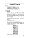
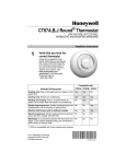
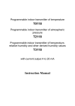
Y Function Specifications Item http://www.delta.com.tw/industrialautomation/ Specifications Control Method I/O Processing Method Extension Digital I/O Module Execution Speed Instruction Sheet Program Language Warning 3 3 3 3 3 3 3 Please read this instruction carefully before use. DOP series Extension Digital I/O Module should be used with DOP-AE series HMI product. Ensure to switch off the power before wiring. Please install this DOP series Extension Digital I/O Module in an enclosure free of airborne dust, humidity, electric shock and vibration. The enclosure should prevent non-maintenance staff from operating the device (e.g. key or specific tools are required for opening the enclosure) in case danger and damage on the device may occur. DO NOT connect input AC power supply to any of the I/O terminals; otherwise serious damage may occur. Check all the wiring again before switching on the power. DO NOT touch any internal circuit in 1 minute after the power is switched off. Do NOT touch any terminal when the power is switched on. Program Capacity Commands Step Relay (Latched) General Step Point Auxiliary Relay Timer Make sure the ground terminal is correctly grounded in order to prevent electromagnetic interference. DO NOT place any heavy objects on the connection port of DOP series Extension Digital I/O Module. Doing so may damage the product. - EXIO (2) 14 (3) R (4) Pointer Index Register AE (5) (1) Product Name DOP: Delta Operation Panel (2) Series EXIO: Extension Digital I/O (3) Input / Output Point 14: 8 input points / 6 output points 28: 16 input points / 12 output points (4) Output Contact Type R: Relay (5) Applicable HMI Series AE: DOP-AE Series HMI Constant Commands + Ladder Diagram + SFC 999 Steps Basic commands: 32 (including the STL commands) [ Installation & Wiring 4.1 Wiring 2 1. Please use the 28-16 AWG (1.5mm ) single-core bare wire (Solid type) or the multi-core wire (Stranded type) for the I/O wiring. The stripped length of Step commands included 22-16AWG Application commands: 59 terminal is 4.5lb-in. Please refer to the specifications of the terminal shown 2. DO NOT place the I/O signal wires and power supply wire in the same General 1280 Points 4.2 Caution Latched 256 Points M512 ~ M767 Environment General Latched 64 Points 63 Points 1 Points 112 Points 16 Points 32bit 13 Points General Latched P 408 Points 192 Points 64 Points T0~T63 (100 ms time base) T64~T126 (10 ms time base) T127 (1 ms time base) C0 ~ C111 C112 ~ C127 C235,C236,C237,C238,C241,C242, C244,C246,C247,C249,C251,C252, C254 (all of them are latched type) D0 ~ D407 D408 ~ D599 P0 ~ P63 2 E, F 16bit: -32768 ~ +32767 32bit: -2147483648 ~ +2147483647 16bit: 0000 ~ FFFF 32bit: 00000000 ~ FFFFFFFF Decimal K Hexadecim al H Monitor / Debug wiring duct. 1. DO NOT install the Extension Digital I/O Module in a place subjected to corrosive or flammable gases, liquids, or airborne dust or metallic particles. 2. DO NOT install the Extension Digital I/O Module in a location high temperature and high humidity (where temperature and humidity will exceed specification). 3. DO NOT install the Extension Digital I/O Module in a location where vibration and shock will exceed specification. Wiring Note 1. Please avoid any conductive debris and tiny metal material enter the Extension Digital I/O Module when screwing and wiring. 2. Allow a minimum space of 50mm between the Extension Digital I/O Module and other control devices, and keep the Extension Digital I/O Module away from the high-voltage lines or any power equipment. I/O check, system execution timeout check, invalid command check, program check and password settings Program execution time display, bit / word, device settings 4.3 Input Point Wiring There are two types of DC inputs, SINK and SOURCE, and they are defined as follows: Sink = (common port for current input S/S) Item / Model Name 3 1 4 Noise Immunity Ambient Temperature / Humidity 2 Vibration / Shock 1. Connection Port Weight 2. Direct Mounting Hole 3. Input / Output Terminals Input Type Input Voltage 1.3 Model Name Active Level Input / Output Input Unit Output Unit Point Type Point Type Response Time X0 Sinking DOP-EXIO14RAE DOP-EXIO28RAE 0.25W 0.5W RS: Frequency: 80MHz ~ 1GHz, 1.4GHz ~ 2.0GHz, Test level 10V/m CS: Frequency: 0.15MHz ~ 80MHz, Test level 10V (HMI power port & I/O line) ESD: Air discharge ±8KV EFT: ±1.5KV (HMI power port) ±1KV (I/O line) Surge: ±2KV (HMI power port) Operation: 0°C ~ 50°C (Temperature), 10 ~ 90% (Humidity), Storage: -40°C ~ 85°C (Temperature), 10 ~ 90% (Humidity) IEC 61131-2 Compliant 5Hz≦f<9Hz = Continuous: 1.75mm / Occasional: 3.5mm 9Hz≦f≦150Hz = Continuous: 0.5g / Occasional: 1.0g X, Y, Z directions for 10 times Approx. 95.5g Approx. 116g DC (SINK or SOURCE) 24VDC (5mA) Off→On, above 16VDC On→Off, below 14.4VDC S/S X0 5VDC, 1A (supplied by HMI) Sourcing Wiring DC Signal IN Input point loop equivalent circuit Wiring loop +24V 24VDC 0V SINK +5V SINK mode S/S +24V OV X0 24VDC S/S X0 X1 X2 Sink Type DC Signal IN Input point loop equivalent circuit Wiring loop +24V Input Point Electric Specifications 4. Nameplate Source = (common port for current output S/S) S/S Electrical Specifications Power Supply Voltage Power Consumption in the figure on the left. < 1.5mm M0 ~ M511, M768 ~ M999, 744 points; M1000 ~ M1279, 280 points*1 E/F the wire should be 6-7mm, and the torque specification of the screw for the Built-in EEPROM *1: M1000, M1001, M1002, M1003, M1020, M1021, M1022, M1067, M10068, and M1161 are the special auxiliary relays (special M). 1.2 Product Outline Power Basic command (30 us) Immediate refresh command available only with I/O of the MPU Application command (30 ~ hundreds us) S10 ~ S127 Self Diagnosis / Protection Z Model Name Batch I/O (refresh) Counter Data Register DOP (1) Stored program, cyclic scan system 100,000 times (3A 250VAC/30VDC) 6,000 times (5A 250VAC/30VDC) Electrical Life Remark 128 Points Digital X Introduction 1.1 Model Explanation Output Point Electric Specifications 24VDC 0V SOURCE +5V SOURCE mode +24V S/S Approx. 10ms X0 0V S/S X0 X1 X2 24VDC Source Type Output Point Electric Specifications DOP-EXIO14RAE DOP-EXIO28RAE 8 5VDC, supplied by HMI 6 Relay Output Type Current Specifications Voltage Specifications 12 Relay Maximum Loading DC Type Sink or Source 16 Response Time Mechanical Life Relay-R 1.5A / 1 Point (5A/COM) 250VAC, below 30VDC 75VA (Inductive) 90 W (Resistive) Approx. 10 ms 2 × 10⁷ times (without load) NOTE 1) The content of this instruction sheet may be revised without prior notice. Please consult our distributors or download the most updated version at http://www.delta.com.tw/industrialautomation.