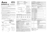
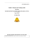
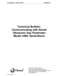
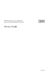
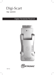
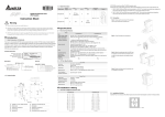
1
2007-01-10 Control Registers 1.3 External Wiring 1mA PT100 Shielding cable *1 5011651800-P2E0 http://www.delta.com.tw/industrialautomation/ DVP04PT-H2 CH1 CR RS-485 # Parameter Latched address L+ LI- Temperature Measurement Module FG Instruction Sheet PT100 Shielding cable *1 ○ R/W CH1 average time L+ ○ R/W CH2 average time L- #4 H’4068 ○ R/W CH3 average time #5 H’4069 ○ R/W CH4 average time #6 H’406A ╳ R Average °C temp. measured at CH1 #7 H’406B ╳ R Average °C temp. measured at CH2 +15V #8 H’406C ╳ R Average °C temp. measured at CH3 AG -15V #9 H’406D ╳ R Average °C temp. measured at CH4 9 Do NOT touch any terminal when the power is switched on. 9 Make sure the ground termnial 9 Use wires with resistance when connect the platinum resistance thermister (RTD) to PLC. is correctly grounded in order to prevent electromagnetic interference. 9 Keep the wire as short as possible between RTD and PLC and the power wire as far away as possible from I/O wire to prevent interference. Introduction 0V DC/DC Converter #10 ~ #11 *1: Wiring for analog input should adopt cables of PT100 temperature sensor or double shielding cable and should be separated from other power cables that may cause interference. Please use 3 wires for PT100. *2: Terminal FG is the ground location for noise suppression. *3: Please connect the terminal on both the power module and DVP04PT-H2 to the system earth point and ground the system contact or connect it to the cover of power distribution cabinet. . Note: DO NOT wire empty terminal sensors (PT100 3-WIRE 100Ω 3850 PPM/°C (DIN 43760 JIS C1604-1989)) and convert them into 14-bit digital signals. Besides, through FROM/TO instructions in DVP-EH2 MPU program, DVP04PT-H2 is able to read and write the data in the module. There are 49 16-bit control registers (CR) in DVP04PT-H2. DVP04PT-H2 displays temperatures in Celsius (resolution: 0.1°C) and Fahrenheit (resolution: 0.18°F). Nameplate Explanation 2.1. Functions Temperature measurement (04PT) module 24 VDC (20.4VDC ~ 28.8VDC) (-15% ~ +20%) Analog output channel 4 channels/module types Current excitation 24Vdc 2.5W Range of input P T100 Analog I/O module spec ification 14 B ITS B a r c o d e , s e r i a l N o . , Ve r s i o n VX.X X temperature 04 PT-H20 T6 500 001 Range of digital MADE I N XXXXX X Production No. H: For EH series MPU H2: For EH2 series MPU Production week Production year (2006) Production plant (Taoyuan) Model type XA: Mixed analog I/O AD: Analog input HC: High-speed counter input DA: Analog output PT: Temperature measurement (PT-100) PU: Single-axis position control TC: Temperature measurement (thermocouple) Version No. Model name 1.2 Product Profile (Indicators, Terminal Block, I//O Terminals) -200 ~ 600 LFG Range of settings in CH1 ~ CH4: K1 ~ K20 Default = K10 Average Celsius temperature measured at CH1 ~ CH4. Unit: 0.1°C ╳ R #13 H’4071 ╳ R Average °F temp. measured at CH2 #14 H’4072 ╳ R Average °F temp. measured at CH3 #15 H’4073 ╳ R Average °F temp. measured at CH4 Average Fahrenheit temperature measured at CH1 ~ CH4. Unit: 0.1°F Reserved #18 H’4076 ╳ R Present °C temp. measured at CH1 #19 H’4077 ╳ R Present °C temp. measured at CH2 #20 H’4078 ╳ R Present °C temp. measured at CH3 #21 H’4079 ╳ R Present °C temp. measured at CH4 Present Celsius temperature measured at CH1 ~ CH4. Unit: 0.1°C Reserved #24 H’407C ╳ R Present °F temp. measured at CH1 #25 H’407D ╳ R Present °F temp. measured at CH2 #26 H’407E ╳ R Present °F temp. measured at CH3 H’407F ╳ R Present °F temp. measured at CH4 Present Fahrenheit temperature measured at CH1 ~ CH4. Unit: 0.1°F Reserved #30 H’4082 ╳ Error status Register for storing all error status. See the table of error status for more information. #31 H’4083 ○ R/W Communication address setting For setting RS-485 communication address. Range: 01 ~ 255 Default = K1 Communication speed (Baud Rate) setting For setting up communication speed: 4,800/9,600/19,200/38,400/57,600/115,200 bps ASCII data format: 7-bit, Even bit, 1 stop bit (7, E, 1) RTU data format: 8-bit, Even bit, 1 stop bit (8, E, 1) Default = H’0002 b0: 4,800 bps b1: 9,600 bps (default) b2: 19,200 bps b3: 38,400 bps b4: 57,600 bps b5: 115,200 bps b6 ~ b13: reserved b14: High/low bit exchange of CRC checksum (only valid in RTU mode) b15: Switch between ASCII/RTU modes; 0 = ASCII mode (default) Overall accuracy R ±0.5% when in full scale (25°C, 77°F) ±1% when in full scale within the range of 0 ~ 55°C, 32 ~ 131°F Response time 200 ms × the number of channels Isolation Isolation between digital area and analog area. No isolation among channels. Digital data format 13 significant bits out of 16 bits are available; in 2’s complement. Average function Yes; available for setting up in CR#2 ~ CR#5; range: K1 ~ K20 Self-diagnosis Upper and lower bound detection/channel Protection circuit for too long period of time may cause damage on internal circuit. The current #32 H’4084 ○ R/W The voltage output is protected by short circuit. Please also be aware that being short b15 b14 b13 b12 b11 b10 b9 output can be open circuit. ERR LED ASCII/RTU mode. Communication mode (RS-485) Communication speed: 4,800/9,600/19,200/38,400/57,600 /115,200 bps ASCII data format: 7-bit, Even bit, 1 stop bit (7, E, 1) RTU data format: 8-bit, Even bit, 1 stop bit (8, E, 1) FG IL- CH 3 L+ FG H’4085 ○ R/W #34 H’4086 ○ Returning to default setting The modules are numbered from 0 to 7 automatically by their distance from MPU. No. 0 is the closest to MPU and No. 7 is the furthest. Maximum 8 modules are allowed to connect to MPU and will not occupy any digital I/O points. L+ I- CH 4 #33 RS-485 cannot be used when connected to PLC MPU. When connected to DVP-PLC MPU in series L- 2.2. Others Max. rated power consumption 24 VDC (20.4VDC ~ 28.8VDC) (-15% ~ +20%), 2.5W supplied by external power Environment Operation/storage Vibration/shock immunity Operation: 0°C ~ 55°C (temperature); 50 ~ 95% (humidity); pollution degree 2 Storage: -40°C ~ 70°C (temperature); 5 ~ 95% (humidity) International standard: IEC1131-2, IEC 68-2-6 (TEST Fc)/IEC1131-2 & IEC 68-2-27 (TEST Ea) b0 Set up by the system. DVP04PT-H2 = H’6402 #28 ~ #29 L- DIN rail clip b1 14 bits (0.18) I/O terminals Mounting port for extension unit/module b2 14 bits (0.1) I- CH 2 L+ POWER, ERROR, A/D indicator Mounting hole b3 0.5Ω or less I- CH 1 Model name Terminals b4 Output impedance L+ Connection port for extension unit/module 6 7 8 9 b5 Resolution D+ DIN rail (35mm) H’4070 -328 ~ 1112 Power Supply 1 2 3 4 5 b6 #27 D- RS-485 0V Unit: mm 1mA b7 K-3,280 ~ K11,120 24V 8 #12 #22 ~ #23 3-WIRE PT100Ω 3850 PPM/°C (DIN 43760 JIS C1604-1989) b8 K-2,000 ~ K6,000 conversion Model/Serial No. Explanation Fahrenheit (°F) Power supply voltage Applicable sensor Delta PLC model name Power input specification Celsius (°C) b9 Reserved Average °F temp. measured at CH1 #16 ~ #17 Specifications Thank you for choosing Delta’s DVP series. DVP04PT-H2 is able to receive 4 points of platinum temperature Points (input + output) 5V Earth (100 or less) 1.1 Model Explanation & Peripherals DVP series AG 24+ b15 b14 b13 b12 b11 b10 Reserved AG *3 System grounding Model name H’4067 Terminal of power module DO NOT connect input AC power supply to any of the I/O terminals; otherwise serious damage may occur. Check all the wiring again before switching on the power. R H’4066 *2 DVP04PT-H2 is an OPEN-TYPE device and therefore should be installed in an enclosure free of airborne dust, humidity, electric shock and vibration. The enclosure should prevent non-maintenance staff from operating the device (e.g. key or specific tools are required to open the enclosure) in case danger and damages on the device may occur. ○ #3 I- 9 Switch off the power before wiring. H’4064 #1 #2 FG 9 Please read this instruction sheet carefully before use. 9 #0 1mA CH4 Warning 9 AG Register content Description #35 ~ #48 R Firmware version CH4 b8 b7 CH3 b6 b5 b4 CH2 b3 b2 b1 CH1 Take the setting of CH1 for example: 1. b0 is reserved. 2. b1 is reserved. 3. When b2 is set as 1, all the settings will return to default settings. ERR LED definition: default of b12 ~ b15 = 1111 1. b12 corresponds to CH1. When b12 = 1 or the scale exceeds the range, ERR LED will flash. 2. b13 corresponds to CH2. When b13 = 1 or the scale exceeds the range, ERR LED will flash. 3. b14 corresponds to CH3. When b14 = 1 or the scale exceeds the range, ERR LED will flash. 4. b15 corresponds to CH4. When b15 = 1 or the scale exceeds the range, ERR LED will flash. Displaying the current firmware version in hex; e.g. version 1.0A is indicated as H’010A For system use Symbols ○: latched (when written in through RS-485 communication) ╳: non-latched R: Able to read data by FROM instruction or RS-485 communication W: Able to write data by TO instruction or RS-485 communication Explanations: 1. CR#0: Model name. The user can read the model name from the program and see if the extension module exists. b0 Fahrenheit temperature measurement mode 2. CR#1, CR#10, CR#11, CR#16, CR#17, CR#22, CR#23, CR#28 and CR#29 are reserved. 3. CR#2 ~ CR#5: The times to average the temperatures measured at CH1 ~ CH4. Range: K1 ~ K20. Default = API 79 D TO Digital output K10. Please note that the average times set in CR#2 ~ CR#5 need to be written in only once. +11,120 Instruction Explanation 4. CR#6 ~ CR#9: The average Celsius temperature measured at CH1 ~ CH4 obtained from the average time settings in CR#2 ~ CR#5. For example, if the average time is set as 10, the content in CR#6 ~ CR#9 will be the +5,560 average of the most recent 10 temperature signals in Celsius at CH1 ~ CH4. Program Example Measured temperature input 5. CR#12 ~ CR#15: The average Fahrenheit temperature measured at CH1 ~ CH4 obtained from the average time -328 F Trial Operation & Troubleshooting 8. CR #30: Error status (see the table below): Hardware malfunction Abnormal digital range Incorrect average times setting Instruction error K4(H’4) K8(H’8) b7 0 b6 0 b5 0 b4 0 b3 0 b2 0 b1 0 b0 1 0 0 0 0 0 0 1 0 0 0 0 0 0 0 0 1 1 0 0 0 0 0 0 0 0 0 0 1 1 0 0 0 0 0 0 0 0 0 K64(H’40) 0 1 0 0 0 0 0 0 K128(H’80) 1 0 0 0 0 0 0 0 reserved Note: Each error status is determined by the corresponding bit (b0 ~ b7) and there may be more than 2 errors occurring at the same time. 0 = normal; 1 = error D10 K1 : The No. of special modules connected to PLC MPU. No. 0 is the module closest to te 2. : CR#. CR (control register) is the 49 16-bit memories built in the special module, numbered in decimal as #0 ~ #48. All operation status and settings of the special module are contained in the CR. 1. When the module is powered for the first time, POWER LED will be on and ERROR LED will be on for 3. 0.5 second. After this, A/D LED will start to flash. FROM/TO instruction is for reading/writing 1 CR at a time. DFROM/DTO instruction is for reading/writing 2 CRs at a time. 2. When the power supply is normal, POWER LED will be on and ERROR LED should be off. When the Hi gh er 16 -b it power supply is less than 19.5V, ERROR LED will keep being on until the power supply goes higher CR #10 than 19.5V. 4. 3. When series connected with PLC MPU, the RUN LED on the MPU will be on and A/D LED will flash. 4. When controlled by RS485, RS-485 LED on the module will flash after receiving the RS-485 instruction. ERROR LED will flash. Remarks Program Example 9. CR#31: The setting of RS-485 communication address. Range: 01 ~ 255. Default = K1. K0 K0 D0 K1 TO K0 K2 D10 K4 FROM K0 K6 D20 K4 FROM K0 K12 D24 K4 FROM K0 K18 D30 K4 FROM K0 K24 D34 K4 M1002 10. CR#32: The setting of RS-485 communication speed. b0: 4,800bps; b1: 9,600bps (default); b2: 19,200bps; b3: CR #9 Designated CR = H ' 6402 D0 (only valid in RTU mode); b15: switching between ASCII mode and RTU mode. Designated device Designated CR D0 CR #5 D0 CR #5 D1 D2 CR #6 CR #7 D1 D2 CR #6 CR #7 D3 D4 CR #8 CR #9 D3 D4 CR #8 CR #9 D5 CR #10 D5 CR #10 16-bit instruction when n=6 38,400bps; b4: 57,600bps; b5: 115,200bps; b6 ~ b13: reserved; b14: high/low bit exchange of CRC checksum De sig na ted CR nu mbe r Number of groups “n” to be transmitted: n = 2 in 16-bit instructions and n = 1 in 32-bit Designated device 5. When the input or output value exceeds the upper bound or falls below the lower bound after conversion, FROM L owe r 1 6- bi t instructions mean the same. M1000 32-bit instruction when n=3 M1083 for switching instruction modes in EH2 series models 11. CR#33: b0 ~ b11: For returning the CR settings to default settings. b12 ~ b15: ERR LED definition. Default: b12 ~ b15 = 1111. 1. When M1083 = Off, during the execution of FROM/TO instruction, all external or internal interruption subroutines will be forbidden. The interruptions are allowed only after FROM/TO instruction finishes its execution. FROM/TO instruction can also be used in an interruption 12. CR#34: Firmware version of the model. 13. CR#35 ~ CR#48: Parameters for system use. RS-485 communication. When using RS-485, the user has to separate the module with MPU first. a. Communication baud rate: 4,800/9,600/19,200/38,400/57,600/115,200 bps. Modbus ASCII/RTU communication protocol: ASCII data format (7-bit, Even bit, 1 stop bit (7, E, 1)); RTU subroutine. 2. END 14. CR#0 ~ CR#34: The corresponding parameter address H’4064 ~ H’4086 are for users to read/write data by b. K6 any I/O points. LED Display 0 0 K16(H’10) K32(H’20) K0 MPU. Maximum 8 modules are allowed to connected to a PLC MPU and they will not occupy 7. CR #24 ~ CR #27: Displaying the present temperature in Fahrenheit at CH1 ~ CH4 K2(H’2) : Number of data to be written at a time Operand rules 1. b15 ~ b8 : Data to be written into CR DTO 6. CR #18 ~ CR #21: Displaying the present temperature in Celsius at CH1 ~ CH4 Content K1(H’1) : CR# in special module to be written X0 -3,280 the average of the most recent 10 temperature signals in Fahrenheit at CH1 ~ CH4. : No. of special module (m1 = 0 ~ 7) Use 32-bit instruction DTO to write the content in D11 and D10 into CR#7 and CR#6 of special module No. 0. Only 1 group of data is written in at a time (n = 1). +1,112 F settings in CR#2 ~ CR#5. For example, if the average time is set as 10, the content in CR#12 ~ CR#15 will be Error status Abnormal power supply Scale exceeds the range or wiring to empty external contact Incorrect mode setting OFFSET/GAIN error Write CR data into special module P When M1083 = On and an interruption signal occurs during the execution of FROM/TO instruction, the interruption will be processed first (with a 100us delay) and the execution of Read the model name from K0 and see if it is DVP04PT-H2: H’6402 FROM/TO will be stopped. After the interruption subroutine finishes its execution, the Set the average times in CH1 ~ CH4 as D10 ~ D13. program will jump to the next instructio of FROM/TO. FROM/TO cannot be used in an If D0 = H’6402, read the average temperature (°C) measured in CH1 ~ CH4 from CR#6 ~ CR#9 and store the 4 interruption subroutine. data in D20 ~ D23. Read the average temperature (°F) measured in CH1 ~ CH4 from CR#12 ~ CR#15 and store the 4 data in D24~ data format (8-bit, Even bit,1 stop bit (8, E, 1)). D27. c. Function: H’03 (read register data); H’06 (write 1 word datum into register); H’10 (write many word data into register). Read the average temperature (°C) measured in CH1 ~ CH4 from CR#18 ~ CR#21and store the 4 data in D30~ D33. d. Latched CR should be written by RS-485 communication to stay latched. CR will not be latched if written by MPU through TO/DTO instruction. Read the average temperature (°F) measured in CH1 ~ CH4 from CR#24 ~ CR#27 and store the 4 data in D34~ D37. Relevant Instructions Temperature/Digital Curve API 78 Celsius temperature measurement mode Digital output D FROM Read CR data in special modules P +6000 Instruction Explanation +3000 +600 C -2000 : CR# in special module to be read : Device for storing read data : Number of data to be read at a time Read CR#24 of special module No. 0 into D0 and CR#25 into D1. Only 2 groups of data are read at a time (n = 2). Measured temperature input -200 C : No. of special module (m1 = 0 ~ 7) Program Example X0 FROM K0 K24 D0 K2 The content of this instruction sheet may be revised without prior notice. Please consult our distributors or download the most updated version at http://www.delta.com.tw/industrialautomation