1
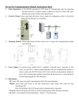
2007-10-12 5011642701-DNT1 DeviceNet Communication Module (CME-DN01) Instruction Sheet DeviceNet is a trademark of the Open DeviceNet Vendor Association, Inc. Please thoroughly read and understand the following contents to ensure correct use before operation. The content of this instruction sheet may be revised without prior notice. Please consult our distributors or download the most updated version at http://www.delta.com.tw/industrialautomation Dimensions Panel Appearance and Dimensions 3 4 250K 500K ADD1 ADD2 BAUD 14.3 [0.57] 59.7 [2.35] 125K 5 NETM OD SP CME-DN01 2 57.3 [2.26] A. 72.2 [2.84] 1 35.8 [1.41] 3.5 [0.14] UNIT: mm(inch) 1. For RS-485 connection to VFD-E 2. Communication port for connecting DeviceNet network 3. Address selector 4. Baud rate selector 5. Three LED status indicators for monitor B. UNIT: mm(inch) STEP 1 Wiring and Settings STEP 2 Refer to following diagram for details. MAC address Date Rate 125K 1: Reserved 2: EV 3: GND 4: SG5: SG+ 6: Reserved 7: Reserved 8: Reserved 250K 500K ADD1 ADD2 BAUD NET MOD SP CME-DN01 V+ Setting baud rate 0 CAN-H Empty CAN-L pin V- D. Setting MAC addresses: use decimal system. BAUD Switch Value 0 1 2 Other C. Baud Rate 125K 250K 500K NOT used ADD1 ADD2 Mounting Method Step1 and step2 show how to mount this communication module onto VFD-E. The dimension in the following is for your reference. Power Supply No external power is needed. Power is supplied via RS-485 port that is connected to VFD-E. An 8 pins RJ-45 cable, which is packed together with this communication module, is used to connect the RS-485 port between VFD-E and this communication module for power. This communication module will perform the function once it is connected. Refer to the following paragraph for LED indications. E. LEDs Display 1. SP: Green LED means in normal condition, Red LED means abnormal condition. 2. Module: Green blinking LED means no I/O data transmission, Green steady LED means I/O data transmission OK. Red LED blinking or steady LED means module communication is abnormal. 3. Network: Green LED means DeviceNet communication is normal, Red LED means abnormal. NOTE Please download the auto EDS generator and user manual at http://www.delta.com.tw/industrialautomation/ DeviceNet 通訊模組(CME-DN01)說明書 DeviceNet 是 ODVA(Open Device Vendor Association) 的註冊商標。 請詳細閱讀下列說明後才使用本產品,以確保使用安全。 由於產品精益求精,當內容規格有所修正時,請洽詢代理商或至台達網站 (http://www.delta.com.tw/ch/product/em/em_main.asp)下載最新版本。 A. 面板尺寸外觀 3 尺寸 4 250K NE TM OD SP CME-DN01 2 57.3 [2.26] 500K AD D1 ADD2 B AUD 14.3 [0.57] 59.7 [2.35] 125K 5 72.2 [2.84] 1 35.8 [1.41] 3.5 [0.14] UNIT: mm(inch) 1. 2. 3. 4. 5. 與 VFD-E 系列連接的 RS-485 通訊接口 連接 DeviceNet 通訊網路接口 位址的選擇開關 鮑率的選擇開關 三個狀態顯示燈以顯示目前此通訊模組運行狀態 B. 接線 UNIT: mm(inch) 步驟 1 步驟 2 MAC address Date Rate 125K 1: Reserved 2: EV 3: GND 4: SG5: SG+ 6: Reserved 7: Reserved 8: Reserved 250K 500K ADD1 ADD2 BAUD NET MOD SP CME-DN01 V+ 設定傳輸速率 0 CAN-H Empty CAN-L pin V- 設定 MAC 位址: 請用十進位設定。 BAUD Switch Value 0 1 2 Other Baud Rate 125K 250K 500K NOT used D. 電源供應 不需額外的電源。電源是由連接至變頻器 (VFD-E)的 RS-485 所提供。CME-DN01 包裝盒內的八支腳 RJ-45 通訊線是用來 連接變頻器的 RS-485 與 CME-DN01 以供應電源。一旦連接 完成,CME-DN01 即可操作。 E. 燈號指示 ADD1 ADD2 C. 安裝方式 步驟 1 及步驟 2 顯示如何將此通訊模組安裝至 VFD-E 變頻 器。附上尺寸供您參考。 1. SP:綠燈表 VFD 系列通訊正常,紅燈表異常。 2. Module:綠燈閃爍表無 I/O data 傳輸;綠燈則表有 I/O data 傳輸。紅燈閃爍及亮紅燈則表此通訊模組模組異常。 3. Network:綠燈表 DeviceNet 通訊正常,紅燈表異常。 NOTE 請至台達網站下載 DeviceNet EDS file 產生器及其使用手冊 http://www.delta.com.tw/ch/product/em/em_main.asp