1
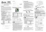
2007-10-12 5011644101-PDT1 Profibus Communication Module (CME-PD01) Instruction Sheet Profibus is a registered trademark of Profibus International. Please thoroughly read and understand the following contents to ensure correct use before operation. The content of this instruction sheet may be revised without prior notice. Please consult our distributors or download the most updated version at http://www.delta.com.tw/industrialautomation A. Panel Appearance Address Switches C. NET LED SP LED Baud Rate 9600 RTU 8, N, 2 Freq. Source Command Source NET SP ADDH ADDL Parameters Setting in VFD-E CME-P D01 D. RS-485 (RJ45) 1: Reserved 2: EV 3: GND 4: SG5: SG+ 6: Reserved 7: Reserved 8: Reserved VFD-E Pr.09.01=1 Pr.09.04=3 Pr.02.00=3 Pr.02.01=3 Power Supply The power of CME-PD01 is supplied from VFD-E. Please connect VFD-E to CME-PD01 by using 8 pins RJ-45 cable, which is packed together with CME-PD01. After connection is completed, CME-PD01 is powered whenever power is applied to VFD-E. E. PROFIBUS Address Profibus-DP Interface (DB9) 1. 2. 3. 4. 5. 6. CME-PD01 has two rotary s select the PROFIBUS address. The set value via 2 address switches, ADDH and ADDL, is in HEX format. ADDH sets the upper 4 bits, and ADDL sets the lower 4 bits of the PROFIBUS address. Address Meaning 1..0x7D 0 or 0x7E..0xFE Valid PROFIBUS address Invalid PROFIBUS address Dimensions NOTE 72.2 [2.84] AD DH A DDL NE T S P CME-P B01 Please download the GSD file and user manual at http://www.delta.com.tw/industrialautomation/ 57.3 [2.26] 59.7 [2.35] 3.6 [0.14] B. SP LED: Indicating the connection status between VFD-E and CME-PD01. NET LED: Indicating the connection status between CME-PD01 and PROFIBUS-DP. Address Switches: Setting the address of CME-PD01 on PROFIBUS-DP network. RS-485 Interface (RJ45): Connecting to VFD-E, and supply power to CME-PD01. PROFIBUS-DP Interface (DB9): 9-PIN connector that connects to PROFIBUS-DP network. Extended Socket: 4-PIN socket that connects to PROFIBUS-DP network. 34.8 [1.37] 3.5 [0.14] Profibus 通訊模組(CME-PD01)說明書 Profibus 為 Profibus international 註冊商標。 請詳細閱讀下列說明後才使用本產品,以確保使用安全。 由於產品精益求精,當內容規格有所修正時,請洽詢代理商或至台達網站 (http://www.delta.com.tw/ch/product/em/em_main.asp)下載最新版本。 A. 面板外觀 Address Switches NET LED SP LED C. Baud Rate 9600 RTU 8, N, 2 Freq. Source Command Source NET SP ADDH ADDL VFD-E 通訊參數的設定 CME-P D01 D. RS-485 (RJ45) 1: Reserved 2: EV 3: GND 4: SG5: SG+ 6: Reserved 7: Reserved 8: Reserved VFD-E Pr.09.01=1 Pr.09.04=3 Pr.02.00=3 Pr.02.01=3 電源供應 CME-PD01 電源由所連接之變頻器所供給,使用標準通訊傳 輸線(附於包裝盒內,連接 RJ-45,8pins) 連接變頻器和 CME-PD01,當變頻器上電後,電源即可輸入 CME-PD01。 E. 位址設定鈕 Profibus-DP Interface (DB9) 1. 2. 3. 4. 5. 6. 外觀尺寸 CME-PD01 提供兩個可旋轉之位址設定鈕來設定,其在 PROFIBUS-DP 網路上的通信位址。兩個旋鈕包括:ADDH 與 ADDL,ADDH 用來設定高 4 位元的通信位址,ADDL 用 來設定低 4 位元的通信位址,並採用 16 進制。 通信位址 說明 1..0x7D 有效的 PROFIBUS 位址 0 或 0x7E..0xFE 無效的 PROFIBUS 位址 NOTE 72.2 [2.84] AD DH AD DL N ET SP CME-P B01 請至台達網站下載 GSD 檔案及其使用手冊 http://www.delta.com.tw/ch/product/em/em_main.asp 57.3 [2.26] 59.7 [2.35] 3.6 [0.14] B. SP LED:變頻器與 CME-PD01 連接狀態指示 NET LED:CME-PD01 與 PROFIBUS-DP 連接狀態 指示 位址設定鈕:設定 CME-PD01 在 PROFIBUS-DP 網路上的通信位址 RS-485 通訊口 (RJ-45):與 VFD-E 系列變頻器連 接並經由此 port 提供電源給 CME-PD01 PROFIBUS-DP 介面 (DB9):用於連接 PROFIBUS-DP 網路 並連插座:使用 4-PIN socket 連接 PROFIBUS-DP 網路 34.8 [1.37] UNIT: mm(inch)