1
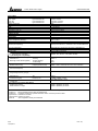
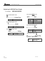
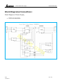
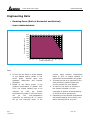
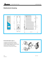
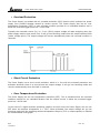
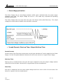
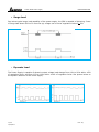
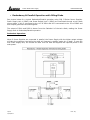
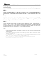
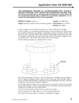
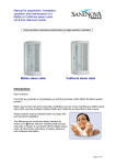
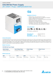
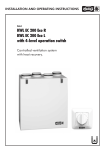
Switch Mode Power Supply DRP024V060W1BA 60W 1Phase CliQ ll DIN Rail Features: Ease of wire connection to terminals Comes with detachable connectors Overload, Overvoltage & Thermal protection Efficiency > 89% Power boost 150% for 3 seconds Expected life time: 10 years Redundancy: Yes (with external ORing diode) RoHS & IP20 compliant Meet Energy Star Level 5 3 years warranty DRP024V060W1BA Summary The new CliQ II DRP024V060W1BA is the latest offering from one of the world’s largest power supply manufacturers - Delta. The product offers a nominal output voltage of 24 V, a wide temperature range from -20°C to +80°C and a minimum holdup time of 20 ms. The state-of-the-art design is made to withstand harsh industrial environments. The rugged, ultra-compact metal case is shock and vibration resistant according to IEC60068-2. 1/13 1/10/2011 The 60 watts DIN Rail power supply provides overvoltage, overload and thermal protection. Due to the wide input voltage range from 85 to 264 VAC, the Delta’s CliQ II power supply is worldwide usable. It also comes with multiple output terminals for fast wiring and easy installation. Rev: 00, Switch Mode Power Supply DRP024V060W1BA Technical Data 60W1Ph Input Data (1) Nominal input voltage and frequency Voltage range Frequency Range Nominal current Inrush current limitation. I2t (+25°C) typ. Mains buffering at nominal load (typ.) Turn-on time Internal fuse Recommended backup fuse: Power circuit-breaker characteristic Leakage current Energy Star Level 100-240VAC / 50-60Hz 85-264VAC (120 – 375 VDC) 47-63Hz 1.5A max @115VAC, 1.0A max @230VAC < 35A @ 230VAC > 20ms @ 115VAC, > 125ms @ 230VAC < 3.0sec. T 3.15 AH / 250V 6A, 10A or 16A : B < 1mA V Output Data (2) Nominal output voltage UN / tolerance Setting range of the output voltage Nominal current De-rating above +50°C Startup with capacitive loads Max. power dissipation idling / nominal load approx. Efficiency Residual ripple / peak switching (20 MHz) (at nominal values) Can be connected in parallel for redundancy and increased capacity Surge voltage protection against internal surge voltages 24VDC±2% 24-28VDC 2.5A > 50°C (2.5% / °C) Max 8,000µF at 25°C 7.4W > 89% typical. < 50mV / < 150mVpp. YES with ORing Diode or Redundancy module YES Certification/Standards Electrical equipment of machines Safety transformers for switched-mode power supply units Electrical safety (of information technology equipment) Industrial Control Equipment Electronic equipment for use in electrical power Installations Safety entry low voltage Safe isolation Protection against electric shock Protection against shock currents, basic requirements for protective separation in electrical equipment Limitation of mains harmonic currents 2/13 1/10/2011 IEC60204-1 (overvoltage category III) TUV BAUART to EN60950-1, UL/C-UL recognized to UL60950-1, CSA C22.2 No. 60950-1, CB scheme to IEC60950-1 UL / C-UL Listed UL508 and CSA C22.2 No. 107.1-01, CSA to CSA C22.2 No.107.1-01 (file no. 181564) EN50178 / IEC62103 PELV (EN60204), SELV (EN60950) DIN.VDE 0100-410 DIN 57100-410 VDE 0106-101 DIN57100-410 Rev: 00, Switch Mode Power Supply General Data Isolation voltage: Input / output Input / PE output / PE Degree of protection Class of protection MTBF Type of housing Dimensions (L / W / H ) Weight STATUS Indicator LED (6) DC OUTPUT OK Climatic Data Ambient temperature (Operating) Ambient temperature (Storage) Humidity at 25°C, non-condensing type test/routine test type test/routine test type test/routine test Vibration (Non-Operating) DRP024V060W1BA 4 KVAC / 3 KVAC 1.5 KVAC / 1.5 KVAC 1.5 KVAC / 500 VAC IP20 Class I with PE connection > 1,000,000hrs. Aluminium (AI5052) 121mmx32mmx125mm 0.37Kg YES (GREEN LED) -20°C to 80°C (> 50°C de-rating) -25°C to 85°C < 95% RH 10Hz to 500Hz @ 30 m/ S2 (3G peak); displacement of 0.35mm; 60min per axis for all X, Y, Z direction. in acc. with IEC 68000-2-6. Shock (in all directions) Pollution degree Climatic class In conformance with EMC guideline 89/336/EEC and low voltage directive 73/23/EEC EMC (electromagnetic compatibility) Immunity to interference according to EN 61000-6-2 EN 61000-4-2 1) Housing Discharge of static electricity (ESD) Contact discharge: Air Discharge: EN 61000-4-3 1) Housing Radiate Field Immunity Frequency/Field intensity: EN 61000-4-4 1) Fast transients (Burst): 30G (300m/S2) in all directions according to IEC60068-2-27 2 according to EN50178 3K3 according to EN 60721 2KV3) / 2KV4) (Level 3) EN 61000-4-5 1) Surge voltage Immunity (Surge): EN 61000-4-6 1) I/O: Conducted Immunity Frequency / Uo: EN 61000-4-11 2) Voltage dips Noise emission according to EN 61000-6-3 Emitted radio interface Radio interference voltage DINRAIL 1AC / 24V DC / 2.5A (EOE11010248) LEVEL 4 8 KV 15 KV LEVEL 3 80MHz - 1GHz / 10V/M with 1kHz tone / 80% modulation 2KV4) Level 3 0.15MHz - 80MHz / 10Vrms. Input: Main Buffering > 20ms. EN55011 (EN55022) CLASS B5 EN55011 (EN55022) CLASS B5 EN55011 corresponds to CISPR11 / EN55022 corresponds to CISPR22 / EN 61000 corresponds to IEC 61000 1) Criterion A: Normal operating behavior within the defined limits. 2) Criterion B: Temporary impairment to operational behavior that is corrected by the device itself. 3) Symmetrical: Conductor to conductor. 4) Asymmetrical: Conductor to ground. 5) Class B: Area of application industry and residential. 3/13 1/10/2011 Rev: 00, Switch Mode Power Supply DRP024V060W1BA Numbering for DIN Rail Power Supply For example: DRP024V060W1BA XX X XXXX XXXX X XX XX X XXXX XXXX X XX XX………………….Product Type XXXX……………Watt DR DinRail XX X XXXX XXXX X XX X………………….Model P Power Supply XX X XXXX XXXX X XX XXXX………………….Voltage 024V 24 Voltage 060W 120W 240W 480W 60 Watt 120 Watt 240 Watt 480 Watt XX X XXXX XXXX X XX X………………….Phase 1 3 1 Phase 3 Phase XX X XXXX XXXX X XX XX………………….Variation (Eg, Customer, material,Etc.) BA 4/13 1/10/2011 Delta standard – metal case Rev: 00, Switch Mode Power Supply DRP024V060W1BA Block Diagrams/Connections: Block Diagram of Power Supply, DRP024V060W1BA 5/13 1/10/2011 Rev: 00, Switch Mode Power Supply DRP024V060W1BA Engineering Data Derating Curve (Both of Horizontal and Vertical) o Model: DRP024V060W1BA 110% Percentage of Max Load (%) 100% 90% 80% 70% 60% 50% 40% 30% 20% 10% 0% -20 -10 0 10 20 30 40 50 Ambient Temperature (C) 60 70 80 Note: 1. Do not use the device in areas outside of the shaded portion shown in the above graph. Internal parts may gradually deteriorate and become damaged. 2. Based on the above graph, if the ambient temperature is greater than 50°C, the output capacity has to be reduced by 2.5% per Celsius temperature increase. If not, the device will go into over-temperature protection by switching off i.e. device will go into bouncing mode. It will 6/13 1/10/2011 recover when ambient temperature drops to 50°C or output capacity is reduced as recommended in the graph. 3. If the device has to be mounted in any other direction, please contact your service provider for more details. 4. In order for the device to function in the manner intended, it is also necessary to observe a lateral spacing of 2cm from other equipments. 5. Depending on the ambient temperature and output capacity of the device, the device housing can be very hot! Rev: 00, Switch Mode Power Supply DRP024V060W1BA Mechanical drawing Device description (Fig. 1) (1) (2) (3) (4) (5) Input terminal block connector Output terminal block connector DC voltage adjustment potentiometer DC OK control LED (green) Universal mounting rail system 7/13 1/10/2011 Rev: 00, Switch Mode Power Supply DRP024V060W1BA Overload Protection The Power Supply is provided with an overload protection (OLP) function which protects the power supply from possible damage caused by excess current. The Power Supply also has an over temperature protection (OTP) in case overload condition persists for an extended duration and is below the overload trigger point but > 100% load. Typically the overload current (IOL) is > ISURGE (150%) output voltage will start dropping when the power supply reaches max power limit. It will go into bouncing mode when the output reaches UVLO (under voltage point). The output voltage will recover automatically when the overload condition is removed. Short Circuit Protection The Power Supply has a short circuit protection which is in line with the overload protection and activates whenever there is a short across the output voltage. It will go into bouncing mode and recovers automatically when the fault is removed. Over Temperature Protection The Power Supply has an over temperature protection (OTP). This is activated when the overload condition persists for an extended duration and the output current is below the overload trigger point but >100% load. In the event of a higher ambient operating condition at 100% load, the Power Supply will run into OTP when the ambient temperature is > 55°C. When activated, the output voltage will go into bouncing mode until the operating ambient temperature drops to 50°C or output capacity is reduced as recommended in the graph. 8/13 1/10/2011 Rev: 00, Switch Mode Power Supply DRP024V060W1BA Overvoltage protection The Power Supply has an overvoltage protection (OVP) and is activated when the power supply feedback circuit fails. The output voltage will not be > 35V under any Line/Load and operating ambient temperature. The Power Supply does not shut down but goes into Hiccup mode (Auto-Recovery). The output voltage will recover back to 24VDC once the fault is removed. Inrush Current, Start-up Time, Output Hold-up Time Inrush Current, Inrush current is the first surge current seen on the input side when AC input is applied to the Power Supply. It is the first pulse captured. See below for the Inrush current in a typical Power Supply. Start-up Time, Start-up time is measured from the point AC input is applied to the point output voltage reaches within 90% of its set value. See below for a typical start-up time characteristic. Rise Time, Rise time is measured from the point output voltage rises from 10% to 90% of its set value. See below for a typical rise time measurement. 9/13 1/10/2011 Rev: 00, Switch Mode Power Supply DRP024V060W1BA Hold-up Time, Hold time is the time when the AC input collapses and o/p voltage retains regulation for a certain period of time is called as hold up time. See in the picture below a typical hold up time characteristic of a power supply. The hold time is measured until the output voltage remains in regulation hence it measured until the output voltage reaches minimum regulation -2% of its set value. Output Voltage Adjust The 24VDC connection is made using the "+" and "–" screw connections. At the time of delivery, the output voltage is 24VDC. The output voltage can be set from 24 to 28VDC on the potentiometer seen as Adjust on the front panel of each power supply. 10/13 1/10/2011 Rev: 00, Switch Mode Power Supply DRP024V060W1BA Surge Load See below typical surge load capability of the power supply, the PSU is capable of delivering 3 secs of Surge load about 150% of IO max the o/p voltage can be out of regulation limits of + 5%. Dynamic Load The Power Supply is capable of dynamic output voltage load change from 10% to 90% within ±5% of regulation limits, and from 0% to 100% within ±10% of regulation limits. See picture below on the dynamic behavior of the Power Supply. 11/13 1/10/2011 Rev: 00, Switch Mode Power Supply DRP024V060W1BA Redundancy & Parallel Operation with ORing Diode See picture below for a typical Redundant/Parallel operation using CliQ II Series Power Supplies. Power Supply Unit 1 (PSU1) and Power Supply Unit 2 (PSU2) are connected through a twin diode where Anode 1 (A1) is connected to the +Ve of PSU1 and A2 is connected to the +Ve of PSU2 and both output ground are shorted together. The output of PSU1 and PSU2 is drawn from the Cathode K of the twin diode, making the Power Supply work in Redundant/Parallel operation. Redundant Operation: When 2 Power Supplies are connected in parallel, the Power Supply with the higher output voltage will take the maximum load while the other will operate in standby mode (at no load). In case the first Power Supply fails, the second will take over the load and supplies the required power to the end system. 12/13 1/10/2011 Rev: 00, Switch Mode Power Supply DRP024V060W1BA Parallel Operation: When 2 Power Supplies are connected in parallel, they can share the load if the following steps are taken. Step 1: Measure the output voltages at no load from A1 to Ground i.e. VA1 to Ground of PSU1 and VA2 to Ground of PSU2. If the voltages are not the same, follow Step 2. If they are the same, skip to Step 3. Step 2: Adjust the output voltages, with the help of VR on the Power Supply front panel market as ADJUST, to the same level. For e.g. if PSU1 is measuring 24.15Vdc and PSU2 is measuring 24.25Vdc, adjust the output voltage of one to be the same as the other. Step 3: Connect the Power Supply to the end system load and measure the output voltages from A1 to Ground i.e. VA1 to Ground of PSU1 and VA2 to Ground of PSU2. Ensure that the output voltages are the same even after the 2 Power Supplies are connected to load. If not, adjust them with the VR available on the front panel. A tolerance of +/-25mV would be acceptable. Note: 1. If the output voltage of any Power Supply is higher, it will take the initial load and share the maximum load. 2. If the output voltages are the same, then an equal load current sharing between the 2 Power Supplies can be achieved. 3. The ORing diode must be of an appropriate rating. The rating must be at least 4 times of the output load current and at least reverse voltage rating of 20Vrr. 4. The use of a heat sink is advised to ensure the ORing Diode does not overheat. 5. Recommended Redundancy Module: DRR-20A 13/13 1/10/2011 Rev: 00,