1
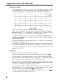
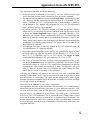
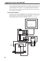
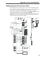
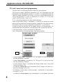
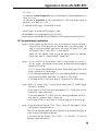
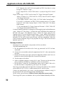
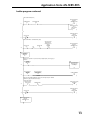
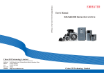
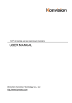
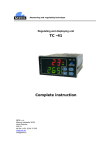
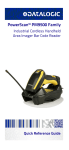
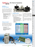
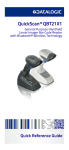
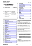
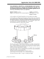
Application Note AN-SERV-005
THIS INFORMATION PROVIDED BY AUTOMATIONDIRECT.COM TECHNICAL
SUPPORT IS SUPPLIED "AS IS", WITHOUT ANY GUARANTEE OF ANY KIND. These
documents are provided by our technical support department to assist others. We
do not guarantee that the data is suitable for your particular application, nor we
assume any responsibility for them in your application.
PRODUCT FAMILY: SureServo
Number: AN-SERV-005
Subject: Sureservo position with incremental position Date issued: Nov-18-2007
Revision: First edition
In this example we will control the position of a rotary table that test widgets.
In this example, we will determine the kinematics of the movement, the sizing of the
servo motor and discuss some design considerations and we will show how to wire
the servo drive to the PLC DL06. We will show the detailed wiring of the drive, the
PLC program code and the servo drive parameter values; at the end we suggest actions
to tune the servo. The control will be done with a C-more panel
See the following diagram to understand the concept.
Device
The rotary table rotates 18 steps in only one direction to complete a total revolution,
that is, rotates 20 degrees in the circle per each step; every time the table stops, a
device is loaded into the table by operators, do some adjustments and then, when the
conditions are set, the new motion is initiated.
Let’s assume that the motion of every step occurs in 3 seconds. In this case, the total
time for the 18 steps is 3x18= 54 seconds; The rest of the time is the time allowed for
loading the air brakes into the rotating table.
The time to load and unload the devices is about 25 seconds.
Friction torque on the rotary table is 10 N-m, obtained empirically
The inertia of the rotary table is 130 Kg-m2 including the widgets.
j: ml/App notes/AN-SERV-005
1
Application Note AN-SERV-005
Kinematic studies
Let’s consider one motion in the time of 3 seconds. We will consider a speed
trapezoidal profile of 1.25 second acceleration, 0.5 second constant speed and 1.25
seconds for deceleration. See the planned motion trapezoidal profile below:
What is the maximum speed that the rotary table will develop?
If the angle is 20 degrees, then the maximum speed on the trapezoidal profile is
determined by 20/1.75 = 11.428 deg/s or 11.428/360 = 0.03175 rev/s or 1.905 rpm
or even in in radians, 11.428/360*2*π= 0.19945 rad/s approximately.
The speed is really very slow: Let’s estimate that the servo motor could run up to a
rated speed to 3000 rpm. We will do later some calculations to define the proper
motor to be used here.
If the rotary table rotates at the maximum speed of 1.905 rpm, the ratio could be up
to 3000 rpm /1.905 rpm = 1574:1
A selection of a gearhead with a bigger ratio, will be useful to increase the torque
to the load and also reduce the reflected inertia and reach a inertia ratio close to the
ideal ratio in the range 10:1 or smaller. However, practical gear head sizes do not
go above a ratio 512 :1.
Dynamics
Let’s do some torque calculations to size the motor.
The dynamic torque will be given by the well known formula Tm -Tr = Jxdω/dt.
The static torque is given by the frictions in the gear reducer and the rotary table.
We know that the inertia of the rotary table is 130 Kg-m2 ; it is important to check
that the dynamical forces will be below the available motor torque.
For this specific case, we do not know for now the inertia of the motor and the gear
reducer at this time. We will calculate the torque needed to move the rotary table
and then we will decide what motor and gear head to use.
The acceleration dω/dt is calculated by knowing that the ramp to go to the
maximum speed is 1.25 second, per the figure above, and the maximum speed is
0.19945 rad/s; that is, the acceleration dω/dt is 0.15956 rad/s2.
The dynamic torque on the rotary table shaft while accelerating is then T = Jxdω/dt
= 130 [Kg-m2]x0.17453 [rad/s2]= 20.74 [N-m].
2
Application Note AN-SERV-005
Let’s add the friction torque: If 10 N-m is considered on the load side, we will have
a total torque during acceleration, of 30.74 N-m.
The result when decelerating is -20.74 + 10 N-m = -10.74 [N-m].
Let’s select a right angle gear head from Neugart USA, type PLS70, that has at least
a torque output of 37 N-m, with the ratio 8:1 with some margin.
There is a trade off between the higher ratio and the torque available. In this case,
the torque on the motor side would be 37/8= 4.625 [N-m] at efficiency of 100%.
This takes us to a large motor, such is the SVM-210.
Let’s increase the ratio to make it 64:1. In this case would be 37/64 = 0.578 N-m.
The motor would be SVL-202. This motor SVL-202 has a rated torque of 0.64 N-m.
Notice that, if the reducer is selected with a ratio of about 120 :1 or more, the motor
will go to higher speeds with lower power (or equivalent torque). This exercise is
left to the reader.
The corresponding 20 degrees will correspond to 20x64 degrees or 1280 degrees,
that corresponds to approximately 12890/360= 3 revolutions and 5555 fractions of
a revolution. This is the angle to move for one step.
This can be treated as an increment, which is constant. Notice that there is an small
error due to approximation on the completion of one table revolution (3.5555
revolutions x18 steps=63.998 revs and not 64 revolutions).
In this assumption, the 200 Watt sureservo motor could do the job, if the efficiency
were 100%, which is not the case. We may adjust the motor, if necessary, after redoing calculations to include the inertias.
In this case we could have an available continuous torque of 0.64 [N-m]x32x0.94
(efficiency)=38.5 [N-m], slightly above the the gearbox rated torque of 37 [N-m].
For this specific case, we the inertia of the motor is 0.18x10⁻⁴ Kg-m2 and the gear
reducer inertia is 0.000102x10⁻⁴ kg-m2.
Let’s now calculate the inertia referred to the motor side:
Motor inertia
= 0.180 x10⁻⁴ kg-m2
Gear inertia
= 0.0001 x10⁻⁴ kg-m2
Coupling (estimated)
= 0.050 x 10⁻⁴ kg-m2
Rotary table inertia/ratio2=
= 130/642
Total inertia referred to motor
= 317.38 x10⁻⁴ kg-m2
= 317.61x10⁻⁴ Kg-m2
The acceleration referred to the motor side is 10.212 rad/s2 (0.15956 rad/s2x64).
The dynamic torque on the motor side is T = Jxdω/dt/η = 0.3243 [N-m].
Let’s add the friction torque: If 10 N-m is considered on the load side, we will have
a friction torque on the motor side of 10/64/0.92 = 0.1698 [N-m] and the total
torque during acceleration, is 0.4941N-m (on the load side is 31.624 N-m).
The result when decelerating is -0.3243 +0.1698 N-m = -0.1545 [N-m]. On the
load side is -9.888 N-m. Note that the addition of the motor and gearhead inertia
was not significant in this case.
The motor torque when at steady speed is 0.1698 [N-m], referred to the motor side,
which is insignificant in this example. The load side reflect to 10.867 N-m./
3
Application Note AN-SERV-005
The maximum speed that the servomotor will run will be 1.905x64 = 121.92 rpm.
A load torque/time chart is shown below:
Control criteria
The next step will be to define the PLC control.
See the figure below to follow the explanation on the next description:
PBA1 - PBA2
20 degrees
Home sensor
Loading point
PBB1 - PBB2
Unloading point
Touch panel for operation
There are 2 operators that are loading and unloading the pieces; they have a button
close to the panel to authorize the next move, when the air brake has been loaded
or unloaded,respectively. This is a touch panel of the type C-more .
The pushbuttons are activated by the operators, for safety reasons, to give the
permissive to start the next step cycle
It is necessary to have a means to return to Home, in case there is a power shutdown
during the operation, to define the proper initial position.
The operation mode will be incremental mode with registers (Pr) Parameter P1-01
should be 101. There are other options not described here.
By the requirements of the control, the PLC and the panel should know at any time
the step that the table is located. This can be done with a simple counter, as
explained later.
4
Application Note AN-SERV-005
The sequence of operation will be the following:
A - When the control is powered up, first the PLC turns on and this will, by logic
and a contactor, turn on the the servo drive, then the servo is enabled.
B - The operator should generate a command to Search Home, with the digital input
DI2, arbitrarily defined, from the panel; the parameter P2-11 should be 127; the
servo is enabled with DI1. The Home position is determined by a proximity
sensor located in DI3, defined with parameter P2-12 as 124. The mechanical
zero is different from the sensor position.
C - A position counter CT0, arbitrarily defined, will keep the position number.
When the PLC is energized, the counter should be reset and the count will be
0. When the Home completed output signal is generated (defined as DO3
arbitrarily), the counter CT0 will increment the count to 1. This would allow the
operators to load the untested piece (and unload the tested one, if there is one
there) and for safety reasons, they should press pushbuttons to acknowledge the
completion of the loading and unloading. This is one criteria. The code can be
done differently if desired.
D - The operators are ready in about 25 seconds or less. Let’s define the input of
these pushbuttons X7, arbitrarily defined.
E - When both acknowledgements occur, the PLC can generate the trigger to move
the rotary table one step, The increment will be defined in P1-15 and P1-16,
being P1-15 3 revolutions and P1-16 5555 counts. The trigger to move
command will be defined in DI5, with parameter P2-13 set as 108.
F - The servo will execute the move and then, when completed the move, it will
turn on the At position output, that arbitrarily will be D04. The counter CT0 will
increment the count to 2 with this. This would allow the operators to load the
untested piece (and unload the tested one, if there). The operators are again
ready in about 25 seconds. They may complete the actions before this time.
Notice that this action is the same as the sequence C.
And then the sequence will continue on the same way until a complete table
rotation has been done. At this time, the counter can be reset. It might exist an offset
due to the errors in calculations. The step 9 will be incremented in other slightly
different increment to compensate the offset errors caused by calculation and keep
the 18 steps exactly at 360 degrees.
The cycle can be repeated as many times as necessary.
Let’s expand on the errors of the calculation. The total counts for a complete rotary
table revolution are 64 revolutions when there is a gear reducer of ratio 64:1; also,
we have seen that every move will be done with 3 revolutions and 5555 counts.
Let’s see what is the addition of all the moves: 3x18 steps gives 54 revolutions;
0.5555x18 gives 9.999 revolutions. That is, at the end of the 18 steps, there is a total
of 63.999 revolutions and then an error of 64 -63.9999 or 0.0001 revolutions. This
can be compensated in several ways, and one of them is to add another increment
in any of the steps, to reach exactly 64 revolutions when the rotary table makes one
complete revolution.
5
Application Note AN-SERV-005
That is, on step 9 we will add an increment of 3 revolutions and 5556 counts, this
can be selected with a position select 0 PLC output digital output to change in this
case the parameters P1-17 and P1-18, using a digital; input on the servo drive.
There is no need to use MODBUS communications here with this control criteria,
even though this is other option.
General control diagram
The control system can be comprised of the Sureservo drive, the PLC and the
accessories such as the thumbs pushbuttons (to acknowledge that the operators are
with the hands free), the home sensor, a proximity switch etc.
See the following diagram to see the relationship among the various devices.
Touch screen panel
PLC DL06
ZIP link
230 Volt, single phase
Rotary table
Home sensor
Operator’s
pushbuttons
servomotor
6
Servo Drive
Application Note AN-SERV-005
Wiring between PLC and servo drive
See on diagram below the selection of the functions and the corresponding outputs:
The C-more panel has been selected to start the system as well as generate the
Home search. The operators acknowledgement and the stop are hardwired.
X2 will receive the signal from the servo drive to report Home completed and X3
will receive the signal from the servo drive to report At position.
Additionally, the home sensor will be wired directly to the digital input DI3. In the
diagram below are shown the control connections between the drive and the PLC,
necessary to make the system work as required.
MCCB
Servo Drive
MC
230 VAC
Single phase
or Three phase
50/60 Hz
R
S
T
L1
L2
D0-06DD1
CN1
+V
C2
Y10
Internally
Supplied
12Vdc
VCC
Servo power
C3
User
supplied
24 VDC
CN2
V-REF
GND
T-REF
GND
PULL HI
VDD
Internally
Supplied
24 VDC
CN1
COM+
COMY11 Servo Enable 101
Y12 Home search 127
Home sensor +
Y14 Pos select 0 111
Y15
Trigger
108
C0
SVC-PFL-0X0
Power
Cable Set
P
D
C
U
V
W
FG
Servo
Motor
Encoder
A
/A
B
/B
Z
/Z
+5V
GND
SVC-EFL-010
Encoder
Cable Set
DI1DI2DI3DI4DI5CN1
DI6DI7DI8-
X5
Servo ready
X1
At Zero speed
X2 Home completed
X3
At Position
X4
Fault
CN1
CN1
DO1+
DO1DO2+
DO2DO3+
DO3DO4+
DO4DO5+
DO5-
CN3
(FG)
X6
Power ON
PBA1 PBA2 PBB1 PBB2
X7
E-STOP
X12
PORT 2
TOUCH PANEL
7
Application Note AN-SERV-005
PLC and C-more touch panel programming
The servo drive has to be programmed to follow the criteria defined.
The maximum speed is defined on parameter P1-55; the acceleration time and
deceleration time defined on parameters P1-34 and P1-35 are defined based on this
speed. the speed is defined in units of rpm. In this case I would recommend to use
122 on the parameter P1-55 and 1.25 seconds on P1-34 and P1-35. P1-36 can be
set to 10 or 20 to make a slight s-curve.
P1-47 is the configuration for the Home search procedure.
When the parameter setting is completed, it is necessary to remove the control
power of the servo drive for a couple of seconds, to allow the saving the parameters
into the drive (This is true for any parameter marked with 3 in user manual).
In order to check that the drive has the proper setting on all the parameters, we
recommend to print the parameters with the help of the Sureservo Pro software.
A list of parameters is shown at the end of this document.
The C-more panel has the following objets (See the figure below) :
C113
C114
- A button Search home, associated to C113. The signal C113 will turn on every
time the pushbutton is touched.
- A button Start indexing, associated to C114. The signal C114 will turn on every
time the pushbutton is touched.
- A numeric display “Step #”, associated to the memory V1000, which is the current
value of the counter CT0,
- An indicator of Power ON or not, associated to the PLC output Y10. Power On is
true when the output Y10 is ON.
-An indicator of “Servo ready” or Servo not ready”, associated to X5. Servo ready is
true when X5 is ON.
- An indicator of At zero speed or not, associated to X1. At zero Speed is true when
8
Application Note AN-SERV-005
X1 is ON.
- An indicator of Home completed or not, associated to X2. Home completed is true
when X2 is ON.
- An indicator of At position or not, associated to X3. The servo output signal At
position is true when X3 is ON.
- 5 indicators of the stages, associated to S0 to S6.
The next step is to create the PLC program code.
We decided to use stage programming in this case.
See on the next section details of the code that will be programmed into the PLC.
PLC programming explanation
Stage 0 - At PLC power up: The first PLC scan or the return to Stage 0 will load a
value of K0 to CTA0 (Basically the counter counts are reset to zero). As
long as no jumps to other stages occur, this stage will keep C0-C17 and
PLC outputs Y10-Y17 reset. This is a safety feature.
When X6 (The selector switch to give the signal power ON) becomes
TRUE, then, there is a jump to Stage 1 "Power ON"
Stage 1- At start we SET Y10 "Servo Power" and Y11"Servo Enable" (Y10 and Y 11
turn on). Stage 1 will monitor various inputs to determine where program
control will JUMP to.
IF C113 (Search Home button on the touch screen panel) goes TRUE, then
there is a jump to S2 "Home Stage"
IF X2 (Homing completed) AND C114 (Start indexing button on the touch
screen panel) are TRUE, then there is a jump to S3 "Run Stage"
IF X12(Stop All PB) is FALSE then there is a jump to ISG 0 "Initial Stage"
Stage 2-When S2 "Home Stage" is active the on delay timer T5 (Home Trigger
Duration) is enabled.
IF the stage S2 is TRUE AND the timer done bit T5 is FALSE, then turn on
Output Y12 "Home Command".
IF the timer done bit T5 is TRUE AND X2 (Homing completed) are TRUE ,
then there is a jump to Stage 1 "Power up"
IF X12 (Stop All PB) is FALSE, there is a jump to Stage ISG 0 "Initial Stage".
Stage 3-IF the count on the counter CT0 is CTA0 = 9, then SET the output Y14 (Turn
ON Position Command Select 0).
This will call Position 2 from the Servo. Position 2 has the offset necessary to
make an exact 360 degree revolution.
IF the count on the counter CT0 is CTA0 < > 9, then RST Y14 (Turn off
Position Command Select 0) .
9
Application Note AN-SERV-005
IF X7 (Operator Start) AND X1(At zero speed) are TRUE, then there is a jump
to Stage S4 "Advance 1 stage"
IF X12 (Stop All PB) is FALSE THEN there is a jump to Stage ISG 0 "Initial
Stage".
Stage 4-IF the stage S4 is TRUE start the timer T6 " Trigger Command Duration".
When S4 "Power On" is TRUE AND T6 is FALSE, then SET the PLC output
Y16 "Trigger Command".
IF CT0 "Index Counter" is TRUE, THEN, OUT C20 "Index Counter Reset".
IF S4 AND X3 (At Position) are TRUE, THEN increment count in CT0 "Index
Counter",IF C20 "Index Counter Reset" is TRUE, THEN, RST CT0 (Resets
index counter).
IF the timer done bit T6 "Trigger Command Duration" is TRUE, THEN RST
Y16 "Trigger Command"(Turn OFF Y16).
In normal Indexing Operation, the program will be toggling back and forth between
stage 1 (Power On), then Stage 3, to check the count and define the increment to
be used and stage 4. This represents Stage 1 "Power ON Stage" going thru the
Operator signal X7 to start the force to go to Stage 3. Stage 3 defines the increment
and then jumps to Stage 4. When in Stage 4, the output Y16 is active for the time
defined in T6, the actual Servo signal to move, and move completion. When the
move has been confirmed, Stage 4 will jump back to Stage 1 and wait for the next
operator signal on X7.
Startup procedures
The program has to be tested in conjunction with the servo drive.
The recommended steps are:
a - Test the operation of the drive with a basic jog command. No PLC has been
connected
b - Connect the servo enable and test the operation of the PLC, when connected to
the drive
c -Connect all the other servo inputs and test the operation of home search. You can
monitor the servo with the help of the Sureservo Pro software.
d - Test the outputs of the drive.
e - Make a complete sequence, running the 18 steps. The count at the end of one
rotary revolution should be 64 revolutions on the Sureservo drive..
f - Tune the drive, if necessary. The load/motor inertias ratio is about 1700 in this
case but the motor is not performing too sharp in this example.
The tuning can be done with the help of the SureServo Pro software: The standard
white cable SVC-PCCFG-CBL is used to connect the PC with the servo.
Create a new configuration, give a name, reset the parameters to default, setting 10
on parameter P2-08, and use the parameters defined earlier:
For this action, go to the menu Utilities>Current config>Print current config.
The tuning of the system can be done with any of the methods offered by the drive.
10
Application Note AN-SERV-005
The task here is to move the load without overshoots, from the home position to all
the positions. In this case, only one position tuning may be needed because the
other positions are basically the same movement.
Finally, document all the project for future troubleshooting and housekeeping,.
Also, create an operating manual for the operators, that do not have to understand
all the details, but they have to understand what makes every action they may
generate. Finally, make backups of the programs.
The servo should be connected to the load in normal condition.The first attempt to
tune the system might result in a behavior as that shown in the figure below. This is
an extreme case.The target of the tuning should result in a behavior similar to as
the following figure:
11
Application Note AN-SERV-005
Ladder program
ISG
Initial Stage after PLC
powerup.
INITIAL STAGE
S0
At first scan, reset Index Counter to "0". Accomplished by LD K0 to CTA0.
_FirstScan
SP0
LD
2
K0
Initial Stage after PLC
powerup.
INITIAL STAGE
S0
OUT
Step position
CTA0
As long as Initial Stage ( ISG 0 ) is active, keep Coils and Outputs "Reset"
Latches when
SureServo is at Zero
Speed ( X1 ).
Mov Started Coil
C0
C17
RST
Initial Stage after PLC
powerup.
INITIAL STAGE
S0
3
This is the external
contactor supplying
power to SureServo.
SERVO POWER
Y10
Y17
RST
External Control Power
or System Power input.
MCR
X6
STOP ALL PB
X12
4
Control Power is Active,
POWER ON
S1
JMP
SG
Control Power is Active,
POWER ON
S1
This rung turns on Y0 ( the contactor providing power to the SureServo drive ) and Y1
(Servo Enable signal to DI 1 on drive).
Control Power is Active,
POWER ON
S1
6
This is the external
contactor supplying
power to SureServo.
SERVO POWER
Y10
SET
This is the signal to
Digital Input 1 on
SureServo
SERVO ENABLE
Y11
SET
Starts the HOME STAGE (SG 2), which initiates and monitors the Homing Sequence of
the SureServo.
This is the signal to
Digital Input 2 on
SureServo ( Home
Trigger ).
HOME PB
C113
7
12
Homing Sequence
operation
HOME STG
S2
JMP
Application Note AN-SERV-005
Ladder program continued
Starts the RUN STAGE ( SG2 )
HOMING CMPLT
X2
This stage defines the
increment
INCREMENT STG
S3
JMP
START INDEX PB
C114
8
Resets Index Counter
(CT 0 )
Index Cntr Rst
C20
SET
Initial Stage after PLC
powerup.
INITIAL STAGE
S0
JMP
STOP ALL PB
X12
9
Starts the ADVANCE 1 STATION STAGE ( SG 4)
STOP ALL PB
X12
C10
Operator Start
X7
This is the signal to
Digital Input 2 on
SureServo ( Home
Trigger ).
HOME PB
C113
10
This stage defines the
increment
INCREMENT STG
S3
JMP
SG
Homing Sequence
operation
HOME STG
S2
Sends 0.3 sec signal from Y2 ( Home Command ) to Digital Input #2 ( Home Trigger ) on
SureServo.
Homing Sequence
operation
HOME STG
S2
TMR
Home Trigger Signal
duration ( 0.3 sec )
Home Trig Dur
T5
12
K3
Homing Sequence
operation
HOME STG
S2
Home Trigger Signal
duration ( 0.3 sec )
Home Trig Dur
T5
13
HOME COMMAND
Y12
OUT
When X2 is true( HOMING COMPLETE, signal comes from Digital Output 3 - HOMING
COMPLETE ). Stage will JUMP back to Stage 1.
Home Trigger Signal
duration ( 0.3 sec )
Home Trig Dur
T5
14
STOP ALL PB
X12
15
HOMING CMPLT
X2
Control Power is Active,
POWER ON
S1
JMP
Initial Stage after PLC
powerup.
INITIAL STAGE
S0
JMP
SG
This stage defines the
increment
INCREMENT STG
S3
13
Application Note AN-SERV-005
Ladder program continued
This rung monitors the value in Counter 0 ( CT 0 ), and when equal to 9, activates Y4,
which sends signal to Digital Input 4 on SureServo. This selects Position 2 Command
(P1.17 ,1.18 and P2.37 ). This Position Command has the calculated OFFSET value that
makes sure the Load ( Index Table ) will move a full 360 degrees.
Step position
CTA0
K9
17
Step position
CTA0
K9
18
Digital Input 4 on
SureServo
POS CMD SLCT 0
Y14
SET
Digital Input 4 on
SureServo
POS CMD SLCT 0
Y14
RST
Operator PB'S must both be made for the duration of 0.5 seconds in this example.
Operator Start
X7
Digital Output 2 from
SureServo triggers this
input that the SureServo
is stopped.
AT ZERO SPEED
X1
19
This stage defines the
increment
INCREMENT STG
S3
Advance 1 station
ADV 1 STG
S4
JMP
Resets Index Counter
(CT 0 )
Index Cntr Rst
C20
RST
20
Initial Stage after PLC
powerup.
INITIAL STAGE
S0
JMP
STOP ALL PB
X12
21
SG
Advance 1 station
ADV 1 STG
S4
TMR
ADVANCE 1 STATION
TIMER
ADV 1 STA TMR
T6
Advance 1 station
ADV 1 STG
S4
23
K3
Advance 1 station
ADV 1 STG
S4
24
18 station Index Table
Counter.
INDEX CNTR
CT0
25
14
ADVANCE 1 STATION
TIMER
ADV 1 STA TMR
T6
Digital Input 5 on
SureServo
TRIGGER COMMAND
Y16
OUT
Resets Index Counter
(CT 0 )
Index Cntr Rst
C20
OUT
Application Note AN-SERV-005
Ladder program continued
11/19/2007
06
Advance 1 station
ADV 1 STG
S4
Digital Output 4 from
SureServo triggers this
input that the SureServo
is "At Position".
AT POSITION
X3
CNT
18 station Index Table
Counter.
INDEX CNTR
CT0
26
Resets Index Counter
(CT 0 )
Index Cntr Rst
C20
Advance 1 station
ADV 1 STG
S4
27
STOP ALL PB
X12
28
29
revision serv 005
K18
ADVANCE 1 STATION
TIMER
ADV 1 STA TMR
T6
Digital Output 2 from
SureServo triggers this
input that the SureServo
is stopped.
AT ZERO SPEED
X1
Digital Output 4 from
SureServo triggers this
input that the SureServo
is "At Position".
AT POSITION
X3
Control Power is Active,
POWER ON
S1
JMP
Initial Stage after PLC
powerup.
INITIAL STAGE
S0
JMP
END
9
Application Note AN-SERV-005
Automation Direct SureServo PRO Drives Configuration Report
Report Generated: 10/9/2007 6:38:41 PM
Config Name: AN-SERV-005 Servo Config.ssc
Motor Code: 11
Rev: 2.001
Parameter
---------
-----
P0.00 - Software Version
2001
P0.01 - Drive Fault Code
0
P0.02 - Drive Status (Front panel display)
0
P0.03 - Analog Monitor Outputs
1
P0.04 - Status Monitor 1
0
P0.05 - Status Monitor
0
P0.06 - Status Monitor 3
0
P0.07 - Status Monitor 4
0
P0.08 - Status Monitor 5
0
P1.00 - External Pulse Input Type
2
P1.01 - Control Mode and Output Direction
1
P1.02 - Speed and Torque Limit
0
P1.03 - Output Polarity Setting
0
P1.04 - Analog Monitor Output Scaling 1 (CH1)
100
P1.05 - Analog Monitor Output Scaling 2 (CH2)
100
P1.06 - Analog Velocity Command Low-pass Filter
0
P1.07 - Analog Torque Command Low-pass Filter
0
P1.08 - Position Command Low-pass Filter
0
P1.09 - Preset Velocity Command / Limit 1
100
P1.10 - Preset Velocity Command / Limit 2
200
P1.11 - Preset Velocity Command / Limit 3
300
P1.12 - Preset Torque Command / Limit 1
100
P1.13 - Preset Torque Command / Limit 2
100
P1.14 - Preset Torque Command / Limit 3
100
P1.15 - Position 1 Command (Revolutions)
P1.16 - Position 1 Command (Counts)
P1.17 - Position 2 Command (Revolutions)
P1.18 - Position 2 Command (Counts)
16
Value
3
5555
3
5556
P1.19 - Position 3 Command (Revolutions)
0
P1.20 - Position 3 Command (Counts)
0
P1.21 - Position 4 Command (Revolutions)
0
Application Note AN-SERV-005
P1.22 - Position 4 Command (Counts)
0
P1.23 - Position 5 Command (Revolutions)
0
P1.24 - Position 5 Command (Counts)
0
P1.25 - Position 6 Command (Revolutions)
0
P1.26 - Position 6 Command (Counts)
0
P1.27 - Position 7 Command (Revolutions)
0
P1.28 - Position 7 Command (Counts)
0
P1.29 - Position 8 Command (Revolutions)
0
P1.30 - Position 8 Command (Counts)
0
P1.31 - Motor Code
11
P1.32 - Motor Stop Mode Selection
0
P1.33 - Position Control Mode (Internal Indexer)
1
P1.34 - Acceleration Time (Internal Indexer)
1250
P1.35 - Deceleration Time (Internal Indexer)
1250
P1.36 - Accel / Decel S-Curve
10
P1.37 - Inertia Mismatch Ratio
1761
P1.38 - Zero Speed Output Threshold
10
P1.39 - Target Speed Output Threshold
3000
P1.40 - Max Analog Velocity Cmd or Velocity Limit
3000
P1.41 - Max Analog Torque Cmd or Torque Limit
100
P1.42 - On Delay Time of Electromagnetic Brake
20
P1.43 - Off Delay Time of Electromagnetic Brake
20
P1.44 - Electronic Gear Numerator 1
1
P1.45 - Electronic Gear Denominator
1
P1.46 - Encoder Output Scaling Factor
1
P1.47 - Homing Mode
222
P1.48 - Homing Speed 1 Fast Search Speed
60
P1.49 - Homing Speed 2 Creep Speed
30
P1.50 - Home Position Offset (Revolutions)
-3
P1.51 - Home Position Offset (Counts)
0
P1.52 - Regenerative Resistor Value
40
P1.53 - Regenerative Resistor Capacity
60
P1.54 - In Position Window
100
P1.55 - Maximum Speed Limit
122
P2.00 - Proportional Position Loop Gain (KPP)
P2.01 - Position Loop Gain Boost
P2.02 - Position Feed Forward Gain (KFF)
P2.03 - Smoothing Constant of Position Feed Forward Gain
35
100
5000
5
17
Application Note AN-SERV-005
P2.04 - Velocity Loop Proportional Gain (KVP)
500
P2.05 - Velocity Loop Gain Boost
100
P2.06 - Velocity Loop Integral Compensation (KVI)
100
P2.07 - Velocity Feed Forward Gain (KVF)
0
P2.08 - Factory Defaults and Security
0
P2.09 - Bounce Filter
2
P2.10 - Digital Input Terminal 1 (DI1)
101
P2.11 - Digital Input Terminal 2 (DI2)
127
P2.12 - Digital Input Terminal 3 (DI3)
124
P2.13 - Digital Input Terminal 4 (DI4)
111
P2.14 - Digital Input Terminal 5 (DI5)
0
P2.15 - Digital Input Terminal 6 (DI6)
108
P2.16 - Digital Input Terminal 7 (DI7)
0
P2.17 - Digital Input Terminal 8 (DI8)
0
P2.18 - Digital Output Terminal 1 (DO1)
101
P2.19 - Digital Output Terminal 2 (DO2)
103
P2.20 - Digital Output Terminal 3 (DO3)
109
P2.21 - Digital Output Terminal 4 (DO4)
105
P2.22 - Digital Output Terminal 5 (DO5)
107
P2.23 - Notch Filter (Resonance Suppression)
P2.24 - Notch Filter Attenuation (Resonance Suppression)
0
P2.25 - Low-pass Filter (Resonance Suppression)
2
P2.26 - External Anti-Interference Gain
0
P2.27 - Gain Boost Control
0
P2.28 - Gain Boost Switching Time
P2.29 - Gain Boost Switching Condition
P2.30 - Auxiliary Function
P2.31 - Auto and Easy Tuning Mode Response Level
10
10000
0
68
P2.32 - Tuning Mode
4
P2.33 - Reserved
0
P2.34 - Overspeed Fault Threshold
P2.35 - Position Deviation Fault Window
18
1000
5000
30000
P2.36 - Position 1 Velocity
122
P2.37 - Position 2 Velocity
122
P2.38 - Position 3 Velocity
1000
P2.39 - Position 4 Velocity
1000
P2.40 - Position 5 Velocity
1000
P2.41 - Position 6 Velocity
1000
Application Note AN-SERV-005
P2.42 - Position 7 Velocity
1000
P2.43 - Position 8 Velocity
1000
P2.44 - Digital Output Mode
0
P2.45 - Index Mode Output Signal Delay Time
1
P2.46 - Index Mode Stations
6
P2.47 - Position Deviation Clear Delay Time
0
P2.48 - Backlash Compensation (Index Mode)
0
P2.49 - Jitter Suppression
0
P2.50 - Clear Position Mode
0
P2.51 - Servo Enable Command
0
P2.52 - Dwell Time 1 - Auto Index Mode
0
P2.53 - Dwell Time 2 - Auto Index Mode
0
P2.54 - Dwell Time 3 - Auto Index Mode
0
P2.55 - Dwell Time 4 - Auto Index Mode
0
P2.56 - Dwell Time 5 - Auto Index Mode
0
P2.57 - Dwell Time 6 - Auto Index Mode
0
P2.58 - Dwell Time 7 - Auto Index Mode
0
P2.59 - Dwell Time 8 - Auto Index Mode
0
P2.60 - Electronic Gear Numerator 2
1
P2.61 - Electronic Gear Numerator 3
1
P2.62 - Electronic Gear Numerator 4
1
P2.63 - Velocity and Position Deviation Scaling Factor
0
P3.00 - Communication Address
2
P3.01 - Transmission Speed
3
P3.02 - Communication Protocol
8
P3.03 - Communication Fault Action
0
P3.04 - Communication Watchdog Time Out
0
P3.05 - Communication Selection
0
P3.06 - Reserved
0
P3.07 - Communication Response Delay Time
0
P4.00 - Fault Record - Most recent (N)
14
P4.01 - Fault Record (N-1)
14
P4.02 - Fault Record (N-2)
9
P4.03 - Fault Record (N-3)
9
P4.04 - Fault Record (N-4)
9
P4.05 - JOG Function
160
P4.06 - Force Outputs Command
0
P4.07 - Input Status
5
19
Application Note AN-SERV-005
P4.08 - Reserved
P4.09 - Output Status
20
8
11
P4.22 - Analog Velocity Input Offset
0
P4.23 - Analog Torque Input Offset
0