1
Dell™ PowerEdge™
M905, M805, M605,
and M600 Systems
Information Update
信息更新
Mise à jour des informations
Informationsaktualisierung
アップデート情報
정보 갱신본
Actualización de información
Dell™ PowerEdge™
M905, M805, M605,
and M600 Systems
Information Update
Notes and Cautions
NOTE: A NOTE indicates important information that helps you make better use
of your computer.
CAUTION: A CAUTION indicates potential damage to hardware or loss of data
if instructions are not followed.
___________________
Information in this document is subject to change without notice.
© 2008 – 2009 Dell Inc. All rights reserved.
Reproduction of these materials in any manner whatsoever without the written permission of Dell Inc.
is strictly forbidden.
Trademarks used in this text: Dell, the DELL logo, PowerEdge, PowerConnect, and OpenManage
are trademarks of Dell Inc.
Other trademarks and trade names may be used in this document to refer to either the entities claiming
the marks and names or their products. Dell Inc. disclaims any proprietary interest in trademarks and
trade names other than its own.
January 2009
P/N P879C
Rev A03
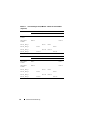
PowerEdge M905 and M805 Blades –
I/O Module Port Mapping
The following tables correct portions of Table 1-12 in the "About Your
System" section of your Hardware Owner’s Manual.
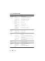
Table 1-1.
I/O Module Port Assignments - Full-Height Blades
Blade 1
I/O Module
A1
B1
C1
C2
B2
A2
Integrated LOM1
Port 1
Port 1
Integrated LOM2
Port 9
Port 9
Mezz1_Fab_C
Port 1
Mezz2_Fab_B
Port 1
Port 1
Mezz3_Fab_C
Port 1
Port 9
Mezz4_Fab_B
Port 9
Port 9
Blade 4
Port 9
I/O Module
A1
B1
C1
C2
B2
A2
Integrated LOM1
Port 4
Port 4
Integrated LOM2
Port 12
Port 12
Mezz1_Fab_C
Mezz2_Fab_B
Port 4
Port 4
Mezz3_Fab_C
Mezz4_Fab_B
Port 4
Port 4
Port 12
Port 12
Port 12
Port 12
Information Update
3
Table 1-1.
I/O Module Port Assignments - Full-Height Blades (continued)
Blade 6
I/O Module
A1
B1
C1
C2
B2
A2
Integrated LOM1 Port 6
Port 6
Integrated LOM2 Port 14
Port 14
Mezz1_Fab_C
Port 6
Mezz2_Fab_B
Port 6
Port 6
Mezz3_Fab_C
Port 6
Port 14
Mezz4_Fab_B
Port 14
Port 14
Blade 8
Port 14
I/O Module
A1
B1
C1
C2
B2
A2
Integrated LOM1 Port 8
Port 8
Integrated LOM2 Port 16
Port 16
Mezz1_Fab_C
Mezz2_Fab_B
Port 8
Port 8
Mezz3_Fab_C
Mezz4_Fab_B
Port 8
Port 8
Port 16
Port 16
Port 16
Port 16
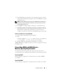
PowerEdge™ M905 and M805 Blades –
Dell™ OpenManage™ Version Requirements
The PowerEdge M905 and M805 blades require OpenManage systems
management software version 5.4.3 or later.
NOTE: OpenManage version 5.4.3 does not support PowerEdge M600
or M605 blades.
4
Information Update
PowerEdge M905 and M805 Blades –
CMC Firmware Requirements
PowerEdge M905 and M805 blades require CMC firmware version 1.2 or
later. If you add these blades to an M1000e enclosure with CMC firmware
older than version 1.2, the new blade will not power on.
NOTE: See the latest Dell Chassis Management Controller User's Guide at
support.dell.com for complete instructions on how to configure and operate
the CMC module.
Updating the CMC Firmware
Downloading the CMC Firmware
Before beginning the firmware update, download the latest firmware version
from the support.dell.com website, and save it to your local system.
The following software components are included with your CMC firmware
package:
•
Compiled CMC firmware code and data
•
Web-based interface, JPEG, and other user interface data files
•
Default configuration files
Use the Firmware Update page to update the CMC firmware to the latest
revision.
NOTE: See the latest Dell Chassis Management Controller User's Guide at
support.dell.com for complete instructions on how to configure and operate
the CMC module.
NOTE: The firmware update, by default, will retain the current CMC settings.
During the update process, you have the option to reset the CMC configuration
settings back to the factory default settings.
Information Update
5
Updating Firmware in a Redundant CMC Configuration
CAUTION: In a redundant CMC configuration, you must update CMC firmware
on both modules. Failure to do so may cause unexpected behavior during a CMC
failover or failback. Use the following procedure for redundant CMC deployments.
1 Locate the secondary or standby CMC by using the RACADM getsysinfo
command, or by using the Chassis Summary page in the Web-based
interface. The status indicator will be solid blue on the primary or active
CMC module and off on the standby or secondary CMC.
2 Update the firmware on the standby CMC first. See "Updating the CMC
Firmware Using the Web-based Interface" or "Updating the CMC
Firmware Using RACADM."
3 Verify that the secondary or standby CMC’s firmware is at the requested
level with the getsysinfo command or through the Web-based interface.
4 After the standby CMC has rebooted, update the firmware on the active
or primary CMC. Allow 10 minutes for the standby CMC to boot.
See "Updating the CMC Firmware Using the Web-based Interface"
or "Updating the CMC Firmware Using RACADM."
5 Verify that the active or primary CMC firmware is at the requested level
using the getsysinfo command or through the Web-based interface.
6 Once both CMCs are updated to the same firmware revision, use the
cmcchangeover command to reset the CMC in the left slot as primary.
Updating the CMC Firmware Using the Web-based Interface
1 Log in to the Web-based interface. See "Logging in to the CMC Using
the Web-Based Interface" in your M1000e Configuration Guide.
2 Click Chassis in the system tree.
3 Click the Update tab. The Updatable Components page appears.
4 On the Updatable Components page, click the CMC name.
The Firmware Update page appears.
6
Information Update
5 In the Value field, type the path on your management station or shared
network where the firmware image file resides, or click Browse to navigate
to the file location.
NOTE: The default CMC firmware image name is firmimg.cmc and the filename
should not be changed. Keep different firmware revisions separated as the file
name will always be the same.
6 Click Update. A dialog box appears asking you to confirm the action.
7 Click Yes to continue. The firmware transfer process will begin and the
status will display the message "Firmware Update in Progress." Once the
CMC update is complete, the CMC will be reset. Once the reset is
complete, you will need to refresh the User Interface page to log in again.
Updating the CMC Firmware Using RACADM
1 Open a CMC command line console and log in.
2 Type:
racadm fwupdate -g -u -a <TFTP server IP address>
-d <filepath> -m <cmc-active|cmc-standby>
See the latest Dell Chassis Management Controller User's Guide at
support.dell.com for complete instructions on how to configure and operate
the CMC module.
PowerEdge M905 and M805 Blades –
Memory Sparing Requirements
The following information updates the memory sparing subsections in
your Hardware Owner’s Manual and these blades’ system information labels.
PowerEdge M905
Memory sparing is supported if 24 identical memory modules (DIMMs)
are installed.
PowerEdge M805
Memory sparing is supported if 16 identical memory modules are installed.
Information Update
7
New Mezzanine Cards
Your blade now supports the following additional mezzanine cards:
•
Broadcom 57710 10Gb Ethernet card
•
Emulex LPe1205-M FC8 card
•
QLogic QME2572 FC8 card
NOTE: CMC firmware version 1.3 is required to support FC8 mezzanine cards
and I/O modules.
For information on installing a mezzanine card, see "Installing System
Components" in your Hardware Owner’s Manual. For detailed information
on configuring a particular card, see the card’s documentation on
support.dell.com.
New I/O Modules
Your system now supports the following additional I/O modules:
•
Dell PowerConnect™ M8024 10Gb Ethernet switch module
•
Mellanox M2401G Infiniband switch module
•
Brocade M5424 FC8 module
NOTE: CMC firmware version 1.3 is required to support FC8 mezzanine cards
and I/O modules.
These modules are hot-pluggable, and may be installed in Fabric B or
Fabric C. (The M8024 Ethernet switch module may also be installed in
Fabric A, but will only operate at 1 Gb in this Fabric.) For general information
on installing I/O modules, see "I/O Modules" in your Hardware Owner’s
Manual.
8
Information Update
PowerConnect M8024 10 Gb Ethernet Switch I/O Module
The PowerConnect M8024 switch module incorporates two option bays
that support the following modules:
•
A 10 Gb Ethernet module with four optical SFP+ connectors
•
A 10 Gb Ethernet module with three copper CX4 uplinks
The modules can be used in any combination and are sold separately.
You can initially configure the switch using either of two methods:
•
Connect an external management system to the switch using an optional
USB type-A form factor serial cable, and configure the switch using a
terminal application.
•
Use the iKVM CMC console (“17th blade”) and the connect switch-n
CMC CLI command. For more information, see the CMC user’s guide.
Once an IP address is assigned to the management VLAN or interface and
the switch is connected to a management network, both Telnet and http are
available through the network.
Information Update
9
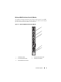
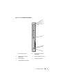
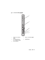
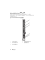
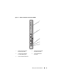
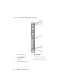
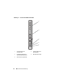
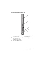
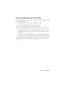
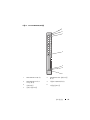
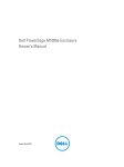
Figure 1-1.
PowerConnect M8024 Switch Module
1
2
3
4
5
10
1
optional module with four SFP+
ports
2
optional module with three CX4 ports
3
serial connector for optional
USB type-A form-factor cable
4
module power indicator
5
status/identification indicator
Information Update
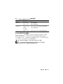
Mellanox M2401G Infiniband Switch I/O Module
The Mellanox M2401G Infiniband switch I/O module includes 24 4x DDR
Infiniband ports. Eight ports are external uplink ports, while 16 internal ports
provide connectivity to the blades in the enclosure.
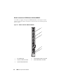
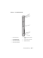
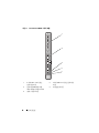
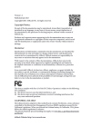
Figure 1-2. Mellanox M2401G Infiniband Switch Module
1
2
3
4
5
1
Infiniband ports (8)
2
port link status indicators (8)
3
port activity indicators (8)
4
module power indicator
5
status/identification indicator
Information Update
11
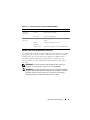
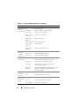
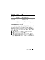
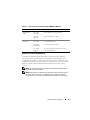
Table 1-2.
Mellanox M2401G Infiniband Switch Indicators
Indicator
Pattern
Description
Link indicator
Green, on
Physical link established
Green, off
No physical link present
Activity indicator Amber, on
Valid logical link to Infiniband network
established
Amber, blinking
Data transfer is occurring
Amber, off
No logical link to Infiniband network
Brocade M5424 FC8 I/O Module
The Brocade M5424 I/O module includes eight external autosensing Fibre
Channel ports (four ports are enabled in the standard configuration and four
additional ports may be enabled as an optional upgrade), 16 internal ports,
and one serial port with an RJ-45 connector. The external Fibre Channel ports
operate at 8 Gb/sec, 4 Gb/sec, or 2 Gb/sec.
NOTE: CMC firmware version 1.3 is required to support FC8 mezzanine cards
and I/O modules.
NOTE: This Fibre Channel switch module includes Short Wave Small Form Factor
Pluggable (SFP) optical transceivers. To ensure proper functionality, use only SFPs
provided with this module.
12
Information Update
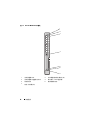
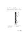
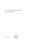
Figure 1-3. Brocade M5424 FC8 I/O Module
1
2
3
4
5
6
7
1
Fibre Channel port (8)
2
Fibre Channel port status
indicator (8)
3
Fibre Channel port speed
indicator (8)
4
serial port (RJ-45 connector)
5
status indicator
6
module power indicator
7
status/identification indicator
Information Update
13
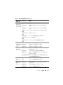
Table 1-3.
Brocade M5424 FC8 I/O Module
Indicator Type Pattern
Description
Fibre Channel Off
port status
Amber on
indicator
Green on
No signal carrier
Online, but no activity
Green
blinking slowly
Online but segmented
Green
blinking quickly
Internal loopback
Green flickering
I/O activity on port
Amber
blinking slowly
Port disabled
Amber
blinking rapidly
Error or fault with port
Fibre Channel Off
port speed
Green on
indicator
Amber on
Module status Off
indicator
Green on
2 Gb link established
4 Gb link established
8 Gb link established
Module is off or enclosure power is off.
All ports are ready for use.
Amber on
Module is booting being reset, or ports are offline.
Green/amber
blinking
Diagnostic message is in error log,
or environmental range is exceeded.
Module power Off
indicator
Green
Status/
Blue on
identification
Blue off
indicator
Amber flashing
14
Signal present but not online
Information Update
Power to the module is off.
Module has power.
Primary module in a stack, if applicable
Secondary module in a stack
Fault condition in module
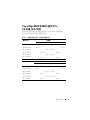
Dell™ PowerEdge™ M905、
M805、M605 和 M600 系统
信息更新
注和警告
注:“注”表示可以帮助您更好地使用计算机的重要信息。
小心:“小心”表示如果不遵循说明,就有可能损坏硬件或
导致数据丢失。
____________________
本说明文件中的信息如有更改,恕不另行通知。
© 2008-2009 Dell Inc. 版权所有,翻印必究。
未经 Dell Inc. 书面许可,严禁以任何形式复制这些材料。
本文中使用的商标:Dell、DELL 徽标、PowerEdge、PowerConnect 和 OpenManage
是 Dell Inc. 的商标。
本说明文件中述及的其它商标和产品名称是指拥有相应商标和产品名称的公司或其制造的
产品。Dell Inc. 对本公司的商标和产品名称之外的其它商标和产品名称不拥有任何专有权。
2009 年 1 月
P/N P879C
Rev. A03
PowerEdge M905 和 M805 刀片 —
I/O 模块端口映射
下表更正了《硬件用户手册》“关于系统”章节中表 1-12 的部分内容。
表 1-1. I/O 模块端口分配 - 全高刀片
刀片 1
I/O 模块
A1
B1
C1
C2
B2
A2
集成 LOM1
端口 1
端口 1
集成 LOM2
端口 9
端口 9
Mezz1_Fab_C
端口 1
Mezz2_Fab_B
端口 1
端口 1
Mezz3_Fab_C
端口 1
端口 9
Mezz4_Fab_B
端口 9
端口 9
刀片 4
端口 9
I/O 模块
A1
B1
C1
C2
B2
A2
集成 LOM1
端口 4
端口 4
集成 LOM2
端口 12
端口 12
Mezz1_Fab_C
Mezz2_Fab_B
端口 4
端口 4
Mezz3_Fab_C
Mezz4_Fab_B
端口 4
端口 4
端口 12 端口 12
端口 12
端口 12
信息更新
17
表 1-1. I/O 模块端口分配 - 全高刀片 (续)
刀片 6
I/O 模块
A1
B1
C1
C2
B2
A2
集成 LOM1
端口 6
端口 6
集成 LOM2
端口 14
端口 14
Mezz1_Fab_C
端口 6
Mezz2_Fab_B
端口 6
端口 6
Mezz3_Fab_C
端口 6
端口 14 端口 14
Mezz4_Fab_B
端口 14
刀片 8
端口 14
I/O 模块
A1
B1
C1
C2
B2
A2
集成 LOM1
端口 8
端口 8
集成 LOM2
端口 16
端口 16
Mezz1_Fab_C
Mezz2_Fab_B
端口 8
端口 8
Mezz3_Fab_C
Mezz4_Fab_B
端口 8
端口 8
端口 16 端口 16
端口 16
端口 16
PowerEdge™ M905 和 M805 刀片 –
Dell™ OpenManage™ 版要求
PowerEdge M905 和 M805 刀片要求使用 5.4.3 版或更高版本的
OpenManage 系统管理软件。
注:OpenManage 5.4.3 版不支持 PowerEdge M600 或 M605 刀片。
18
信息更新
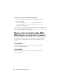
PowerEdge M905 和 M805 刀片 —
CMC 固件要求
PowerEdge M905 和 M805 刀片要求 CMC 固件为 1.2 版或更高版本。
如果您将这些刀片装在 CMC 固件低于版本 1.2 的 M1000e 机壳上,
新刀片将无法通电。
注:请参阅 support.dell.com 上的最新《Dell 机箱管理控制器用户指南》
以了解有关如何配置和操作 CMC 模块的完整说明。
更新 CMC 固件
下载 CMC 固件
在开始固件更新之前,从 support.dell.com Web 站点下载最新的固件
版本,并保存到您的本地系统。
CMC 固件包包含以下软件组件:
•
编译的 CMC 固件代码和数据
•
基于 Web 的界面、JPEG 和其它用户界面数据文件
•
默认配置文件
使用 Firmware Update(固件更新)页面,将 CMC 固件更新为最新
版本。
注:请参阅位于 support.dell.com 的最新《Dell 机箱管理控制器用户指南》
以了解有关如何配置和操作 CMC 模块的完整说明。
注:默认情况下,固件更新会保留当前的 CMC 设置。更新过程中,
可以选择将 CMC 配置设置重设为出厂默认设置。
更新冗余 CMC 配置中的固件
小心:在冗余 CMC 配置中,必须更新两个模块的 CMC 固件。否则可能会
导致在 CMC 故障转移或故障回复期间出现意外行为。使用以下步骤进行冗
余 CMC 部署。
1 使用 RACADM getsysinfo 命令或使用 Chassis Summary(机箱摘要)
页面(位于基于 Web 的界面中)查找次级或备用 CMC。可以看到主
CMC 或活动 CMC 模块的状态指示灯呈纯蓝色,备用 CMC 或次级
CMC 的指示灯不亮。
2 首先更新备用 CMC 上的固件。请参阅“使用基于 Web 的界面更新
CMC 固件”或“使用 RACADM 更新 CMC 固件”。
信息更新
19
3 使用 getsysinfo 命令或通过基于 Web 的界面验证次级 CMC 或备用
CMC 的固件已达到所要求的水准。
4 重新引导备用 CMC 后,更新活动或主 CMC 上的固件。请留出 10 分
钟引导备用 CMC。
请参阅“使用基于 Web 的界面更新 CMC 固件”或“使用 RACADM
更新 CMC 固件”。
5 使用 getsysinfo 命令或通过基于 Web 的界面验证活动 CMC 或主 CMC
的固件已达到所要求的水准。
6 一旦两个 CMC 都更新为相同的固件修订版本,使用 cmcchangeover
命令将左插槽中的 CMC 重设为主 CMC。
使用基于 Web 的界面更新 CMC 固件
1 登录到基于 Web 的界面。请参阅 M1000e《 配置指南》中的“使用基
于 Web 的界面登录到 CMC” 。
2 单击系统树中的 Chassis(机箱)。
3 单击 Update(更新)选项卡。此时将会显示 Updatable Components
(可更新组件)页。
4 在 Updatable Components(可更新组件)页面上,单击 CMC name
(CMC 名称)。显示 Firmware Update(固件更新)页面。
5 在 Value(值)字段中键入固件映像文件驻留的管理站或共享网络的
路径,或单击 Browse(浏览)导航到文件位置。
注:默认 CMC 固件映像名称为 firmimg.cmc,且文件名不可更改。
由于文件名始终相同,所以必须分开保存不同的固件版本。
6 单击 Update (更新)。显示一个对话框,要求您确认刚才的操作。
7 单击 Yes(是)继续。固件传输过程将开始,显示的状态消息为
“Firmware Update in Progress”(正在更新固件)。CMC 更新一旦
完成,将重设 CMC。重设完成后,将需要刷新 User Interface
(用户界面)页面以再次登录。
20
信息更新
使用 RACADM 更新 CMC 固件
1 打开 CMC 命令行控制台并登录。
2 键入:
racadm fwupdate -g -u -a <TFTP 服务器 IP 地址 > -d
< 文件路径 > -m <cmc-active|cmc-standby>
请参阅 support.dell.com 上的最新《Dell 机箱管理控制器用户指南》
以了解有关如何配置和操作 CMC 模块的完整说明。
PowerEdge M905 和 M805 刀片— 内存备用要求
以下信息是对《硬件用户手册》中的内存备用小节以及这些刀片的系统信
息标签的更新。
PowerEdge M905
如果已安装了 24 个完全相同的内存模块 (DIMM) ,则可支持内存备用。
PowerEdge M805
如果已安装了 16 个完全相同的内存模块,则可支持内存备用。
新夹层卡
您的刀片目前支持以下附加的夹层卡:
•
Broadcom 57710 10Gb 以太网卡
•
Emulex LPe1205-M FC8 卡
•
QLogic QME2572 FC8 卡
注:需要 CMC 固件版本 1.3 才能支持 FC8 夹层卡和 I/O 模块。
有关夹层卡的信息,请参阅《硬件用户手册》中的“安装系统组件”。
有关配置特定卡的详情,请参阅 support.dell.com 上该卡的说明文件。
信息更新
21
新 I/O 模块
您的系统现在支持以下附加 I/O 模块:
•
Dell PowerConnect™ M8024 10Gb 以太网交换机模块
•
Mellanox M2401G Infiniband 交换机模块
•
Brocade M5424 FC8 模块
注:需要 CMC 固件版本 1.3 才能支持 FC8 夹层卡和 I/O 模块。
这些模块可以热插拔,并且可安装到结构 B 或结构 C 中。(M8024 以太
网交换机模块还可以安装到结构 A 中,但在此结构中将只能以 1 Gb 速度
运转。)有关安装 I/O 模块的一般信息,请参阅《硬件用户手册》
中的“I/O 模块”。
PowerConnect M8024 10 Gb 以太网交换机 I/O 模块
PowerConnect M8024 交换机模块整合了两个可选的托架支持以下模块:
•
带有四个光学 SFP+ 连接器的 10 Gb 以太网模块
•
带有三个铜缆 CX4 上行链路的 10 Gb 以太网模块
这些模块可任意组合使用,并且单独销售。
可以使用以下两种方法中的任一种初始配置交换机:
•
使用可选的 USB A 类外形尺寸串行电缆将外部管理系统连接至交
换机,然后使用终端应用程序配置该交换机。
•
使用 iKVM CMC 控制台(“第 17 个刀片”)和 connect switch-n
CMC CLI 命令。有关详情,请参阅 CMC user's guide(CMC 用户
指南)。
一旦将 IP 地址分配给管理 VLAN 或接口并且交换机连接至管理网络后,
Telnet 和 http 均通过该网络可用。
22
信息更新
图 1-1. PowerConnect M8024 交换机模块
1
2
3
4
5
1
带有四个 SFP+ 端口的可
选模块
2
带有三个 CX4 端口的可选模块
3
用于可选的 USB A 类外
型尺寸电缆的串行连接器
4
模块电源指示灯
5
状态 / 标识指示灯
信息更新
23
Mellanox M2401G Infiniband 交换机 I/O 模块
Mellanox M2401G Infiniband 交换机 I/O 模块包括 24 个 4x DDR
Infiniband 端口。其中 8 个是外部上行链路端口,另外 16 个内部端口可连
接到硬盘柜中的刀片。
图 1-2. Mellanox M2401G Infiniband 交换机模块
1
2
3
4
5
1
Infiniband 端口 (8)
2
端口链接状态指示灯 (8)
3
端口活动指示灯 (8)
4
模块电源指示灯
5
状态 / 标识指示灯
24
信息更新
表 1-2. Mellanox M2401G Infiniband 交换机指示灯
指示灯
显示方式
说明
链接指示灯
绿色,亮起
已建立物理链接
绿色,不亮
没有建立物理链接
琥珀色,亮起
已建立与 Infiniband 网络有效的逻辑链接
琥珀色、
正在闪烁
正在进行数据传输
琥珀色,不亮
没有建立与 Infiniband 网络的逻辑连接
活动指示灯
Brocade M5424 FC8 I/O 模块
Brocade M5424 I/O 模块包括八个外部自动感应的光纤信道端口(标准
配置中启用四个端口,而另四个端口可作为可选的升级端口来启用)、
16 个内部端口以及一个使用 RJ-45 连接器的串行端口。外部光纤信道端口
以 8 Gb/ 秒、4 Gb/ 秒或 2 Gb/ 秒的速度运转。
注:需要 CMC 固件版本 1.3 才能支持 FC8 夹层卡和 I/O 模块。
注:此光纤信道交换机模块包含短波小型可插拔 (SFP) 光学收发器。
为了确保正常工作,请仅使用此模块附带的 SFP。
信息更新
25
图 1-3. Brocade M5424 FC8 I/O 模块
1
2
3
4
5
6
7
1
光纤信道端口 (8)
2
光纤信道端口状态指示灯 (8)
3
光纤信道端口速度指示灯 (8)
4
串行端口(RJ-45 连接器)
5
状态指示灯
6
模块电源指示灯
7
状态 / 标识指示灯
26
信息更新
表 1-3. Brocade M5424 FC8 I/O 模块
指示灯类型
显示方式
说明
光纤信道端口
状态指示灯
不亮
无信号载体
琥珀色亮起
信号出现但未联机
绿色亮起
联机,但无活动
绿色缓慢闪烁
联机但已分段
绿色快速闪烁
内部环回
绿色闪烁
端口上有 I/O 活动
琥珀色缓慢
闪烁
端口已禁用
琥珀色快速
闪烁
端口错误或故障
不亮
2 Gb 链接已建立
绿色亮起
4 Gb 链接已建立
琥珀色亮起
8 Gb 链接已建立
不亮
模块关闭或机壳电源关闭。
绿色亮起
所有端口均已准备就绪。
琥珀色亮起
模块正在引导重设,或端口脱机。
绿色 / 琥珀
色闪烁
错误日志中的诊断消息,或超出环境范围。
模块电源指
示灯
不亮
模块电源关闭。
绿色
模块已通电。
状态 /
标识指示灯
蓝色亮起
堆栈中的主要模块 (如果可用)
蓝色熄灭
堆栈中的备用模块
琥珀色闪烁
模块出现故障
光纤信道端口
状态指示灯
模块状态指
示灯
信息更新
27
28
信息更新
Systèmes Dell™ PowerEdge™
M905, M805, M605 et M600
Mise à jour
des informations
Remarques et précautions
REMARQUE : Une REMARQUE indique des informations importantes qui peuvent
vous aider à mieux utiliser votre ordinateur.
PRÉCAUTION : Une PRÉCAUTION indique un risque de dommage matériel
ou de perte de données en cas de non-respect des instructions.
____________________
Les informations contenues dans ce document sont sujettes à modification sans préavis.
© 2008-2009 Dell Inc. Tous droits réservés.
La reproduction de ce document de quelque manière que ce soit sans l'autorisation écrite de Dell Inc.
est strictement interdite.
Marques mentionnées dans ce document : Dell, le logo DELL, PowerEdge, PowerConnect
et OpenManage sont des marques de Dell Inc.
D'autres marques commerciales et noms de marque peuvent être mentionnés dans ce document
pour faire référence aux entités se réclamant de ces marques et de ces noms ou de leurs produits.
Dell Inc. décline tout intérêt dans l'utilisation des marques déposées et des noms de marque ne lui
appartenant pas.
Janvier 2009
N/P P879C
Rév. A03
Serveurs lames PowerEdge M905 et M805 –
Mappage des ports de module d'E/S
Les tableaux suivants corrigent les parties du tableau 1-12 de la section “About
Your System (Présentation du système)” du document Hardware Owner’s
Manual (Manuel du propriétaire).
Tableau 1-1.
Affectation par port des modules d'E/S - Serveurs lames pleine hauteur
Serveur lame 1
Module d'E/S
A1
B1
C1
C2
B2
A2
Carte LOM1 intégrée
Port 1
Port 1
Carte LOM2 intégrée
Port 9
Port 9
Carte Mezz1_circuit_C
Port 1
Carte Mezz2_circuit_B
Port 1
Port 1
Carte Mezz3_circuit_C
Port 1
Port 9
Carte Mezz4_circuit_B
Port 9
Port 9
Serveur lame 4
Port 9
Module d'E/S
A1
B1
C1
C2
B2
A2
Carte LOM1 intégrée
Port 4
Port 4
Carte LOM2 intégrée
Port 12
Port 12
Carte Mezz1_circuit_C
Carte Mezz2_circuit_B
Port 4
Port 4
Carte Mezz3_circuit_C
Carte Mezz4_circuit_B
Port 4
Port 4
Port 12
Port 12
Port 12
Port 12
Mise à jour des informations
31
Tableau 1-1.
(suite)
Affectation par port des modules d'E/S - Serveurs lames pleine hauteur
Serveur lame 6
Module d'E/S
A1
B1
C1
C2
B2
A2
Carte LOM1 intégrée
Port 6
Port 6
Carte LOM2 intégrée
Port 14
Port 14
Carte Mezz1_circuit_C
Port 6
Carte Mezz2_circuit_B
Port 6
Port 6
Carte Mezz3_circuit_C
Port 6
Port 14
Carte Mezz4_circuit_B
Port 14
Port 14
Serveur lame 8
Port 14
Module d'E/S
A1
B1
C1
C2
B2
A2
Carte LOM1 intégrée
Port 8
Port 8
Carte LOM2 intégrée
Port 16
Port 16
Carte Mezz1_circuit_C
Carte Mezz2_circuit_B
Port 8
Port 8
Carte Mezz3_circuit_C
Carte Mezz4_circuit_B
Port 8
Port 8
Port 16
Port 16
Port 16
Port 16
Configuration de Dell™ OpenManage™ pour
les serveurs lames PowerEdge™ M905 et M805
Les serveurs lames PowerEdge M905 et M805 requièrent le logiciel de gestion
de systèmes OpenManage 5.4.3 ou version ultérieure.
REMARQUE : OpenManage version 5.4.3 ne prend pas en charge les serveurs
lames PowerEdge M600 et M605.
32
Mise à jour des informations
Micrologiciel CMC requis pour les serveurs
lames PowerEdge M905 et M805
Les serveurs lames PowerEdge M905 et M805 requièrent le micrologiciel
CMC 1.2 ou version ultérieure. Si vous installez ces serveurs lames dans
une baie M1000e et utilisez une version du micrologiciel CMC antérieure
à la version 1.2, ils ne démarreront pas.
REMARQUE : Pour des instructions complètes concernant la configuration et
l'utilisation du module CMC, reportez-vous au document Dell Chassis Management
Controller User's Guide (Contrôleur de gestion de châssis Dell - Guide d'utilisation)
le plus récent disponible sur le site support.dell.com.
Mise à jour du micrologiciel CMC
Téléchargement du micrologiciel CMC
Avant de procéder à la mise à jour du micrologiciel, téléchargez-en la dernière
version à partir du site support.dell.com et enregistrez-la sur le système local.
Le package du micrologiciel CMC se compose des éléments suivants :
•
Code compilé et données du micrologiciel CMC
•
Fichiers de données de l'interface Web, JPEG et des autres interfaces
utilisateur
•
Fichiers de configuration par défaut
Pour installer la dernière version du micrologiciel CMC, accédez à la page
Firmware Update (Mise à jour du micrologiciel).
REMARQUE : Pour des instructions complètes concernant la configuration et
l'utilisation du module CMC, reportez-vous au document Dell Chassis Management
Controller User's Guide (Contrôleur de gestion de châssis Dell - Guide d'utilisation)
le plus récent disponible sur le site support.dell.com.
REMARQUE : Par défaut, la mise à jour du micrologiciel ne modifie pas les
paramètres courants du module CMC. Au cours de la mise à jour, vous pouvez
réinitialiser les paramètres de configuration du module CMC afin de rétablir
les valeurs par défaut définies en usine.
Mise à jour des informations
33
Mise à jour du micrologiciel dans une configuration composée de modules CMC
redondants
PRÉCAUTION : Dans une configuration de modules CMC redondants, vous devez
mettre à jour le micrologiciel CMC des deux modules. Sinon, le système risque de
se comporter de façon imprévisible lors d'un basculement ou d'une restauration
impliquant les modules CMC. Pour les déploiements de modules CMC redondants,
procédez comme suit :
1 Identifiez le module CMC secondaire (de secours) à l'aide de la
commande RACADM getsysinfo ou de la page Chassis Summary
(Récapitulatif du châssis) de l'interface Web. Le voyant d'état du
module CMC principal ou actif est bleu fixe, tandis que celui du module
de secours ou d'attente est éteint.
2 Mettez tout d'abord le micrologiciel à jour sur le module CMC de secours.
Voir les sections “Mise à jour du micrologiciel du module CMC via
l'interface Web” ou “Mise à jour du micrologiciel du module CMC à l'aide
de RACADM”.
3 Vérifiez que le module de secours exécute la version du micrologiciel
requise. Pour ce faire, vous pouvez utiliser la commande getsysinfo ou
l'interface Web.
4 Après le redémarrage du module CMC secondaire, mettez le micrologiciel
à jour sur le module CMC principal (actif). Patientez environ 10 minutes
pour que le démarrage du module CMC de secours soit entièrement
terminé.
Voir les sections “Mise à jour du micrologiciel du module CMC via
l'interface Web” ou “Mise à jour du micrologiciel du module CMC à l'aide
de RACADM”.
5 Vérifiez que le module actif (principal) exécute la version du micrologiciel
requise. Pour ce faire, vous pouvez utiliser la commande getsysinfo ou
l'interface Web.
6 Une fois le micrologiciel des deux modules CMC à jour, utilisez la
commande cmcchangeover pour redéfinir le module CMC installé
dans le logement de gauche en tant que module principal.
34
Mise à jour des informations
Mise à jour du micrologiciel du module CMC via l'interface Web
1 Ouvrez une session sur le module CMC par l'intermédiaire de l'interface
Web. Reportez-vous à la section “Logging in to the CMC Using the WebBased Interface” (Ouverture de session sur le module CMC à l'aide
de l'interface Web) du document Configuration Guide (Guide de
configuration) du M1000e.
2 Sélectionnez Chassis (Châssis) dans l'arborescence.
3 Cliquez sur l'onglet Update (Mise à jour). La page Updatable
Components (Composants actualisables) s'affiche.
4 Dans cette page, cliquez sur le nom du module CMC. La page Firmware
Update (Mise à jour du micrologiciel) s'affiche.
5 Dans le champ Value (Valeur), tapez le chemin d'accès de la station de
gestion ou du réseau partagé contenant le fichier image du micrologiciel
ou cliquez sur Browse (Parcourir) pour accéder à l'emplacement approprié.
REMARQUE : Par défaut, le fichier contenant l'image du micrologiciel du
module CMC se nomme firmimg.cmc. Ce nom ne doit pas être modifié. Placez
les différentes révisions de micrologiciel dans des répertoires distincts étant donné
que le nom du fichier sera toujours le même.
6 Cliquez sur Update (Mise à jour). Une boîte de dialogue vous demande
de confirmer l'opération.
7 Cliquez sur Yes (Oui) pour continuer. La procédure de transmission
du micrologiciel démarre et le message “Firmware Update in Progress”
(Mise à niveau du micrologiciel en cours) est affiché. À l'issue de la mise
à jour du module CMC, celui-ci est automatiquement réinitialisé.
À la fin de la réinitialisation, actualisez la page de l'interface utilisateur,
puis rouvrez une session.
Mise à jour des informations
35
Mise à jour du micrologiciel du module CMC à l'aide de RACADM
1 Ouvrez une console de ligne de commande sur le module CMC et ouvrez
une session.
2 Tapez :
racadm fwupdate -g -u -a <adresse IP du serveur
TFTP> -d <chemin du fichier> -m <cmc-active|cmcstandby>
Pour des instructions complètes concernant la configuration et l'utilisation
du module CMC, reportez-vous au document Dell Chassis Management
Controller User's Guide (Contrôleur de gestion de châssis Dell - Guide
d'utilisation) le plus récent disponible sur le site support.dell.com.
Configuration de la mémoire de réserve sur
les serveurs lames PowerEdge M905 et M805
Les informations suivantes remplacent les sous-sections du Hardware Owner’s
Manual (Manuel du propriétaire) relatives à la mémoire de réserve sur les
systèmes PowerEdge M905 et M805 ainsi qu'à leur étiquette d'information
système.
PowerEdge M905
La mémoire de réserve est prise en charge si 24 barrettes de mémoire (DIMM)
identiques sont installées.
PowerEdge M805
La mémoire de réserve est prise en charge si 16 barrettes de mémoire (DIMM)
identiques sont installées.
36
Mise à jour des informations
Prise en charge de nouvelles cartes mezzanines
Le serveur lame prend désormais en charge les cartes mezzanines suivantes :
•
Carte Ethernet Broadcom 57710 10 Gb
•
Carte Emulex LPe1205-M pour réseau FC8
•
Carte QLogic QME2572 pour réseau FC8
REMARQUE : Les cartes mezzanines et les modules d'E/S pour réseau FC8 ne sont
pris en charge qu'avec la version 1.3 du micrologiciel CMC.
Pour plus d'informations sur l'installation d'une carte mezzanine, reportez-vous
à la section “Installing System Components” (Installation des composants du
système) du document Hardware Owner’s Manual (Manuel du propriétaire).
Pour obtenir des informations détaillées sur la configuration d'une carte
particulière, reportez-vous à la documentation de la carte sur le site
support.dell.com.
Prise en charge de nouveaux modules d'E/S
Le système prend désormais en charge les modules d'E/S suivants :
•
Module commutateur Ethernet Dell PowerConnect™ M8024 10 Gb
•
Module commutateur Mellanox M2401G Infiniband
•
Module Brocade M5424 pour réseau FC8
REMARQUE : Les cartes mezzanines et les modules d'E/S pour réseau FC8 ne sont
pris en charge qu'avec la version 1.3 du micrologiciel CMC.
Ces modules sont enfichables à chaud. Vous pouvez les installer dans la
structure B ou C. (Vous pouvez installer le module commutateur Ethernet
M8024 dans la structure A, mais celui-ci ne fonctionnera qu'à 1 Gb.) Pour
obtenir des informations générales sur l'installation des modules d'E/S, reportezvous à la section “I/O Modules” (Modules d'E/S) du document Hardware
Owner’s Manual (Manuel du propriétaire).
Mise à jour des informations
37
Module commutateur d'E/S Ethernet PowerConnect M8024 10 Gb
Ce module commutateur comporte deux baies optionnelles qui peuvent
accueillir les modules suivants :
•
Un module Ethernet 10 Gb équipé de deux connecteurs SFP+ optiques
•
Un module Ethernet 10 Gb équipé de trois liaisons sortantes cuivre
(CX4)
Ces modules sont vendus séparément et vous pouvez les utiliser dans n'importe
quelle combinaison.
Vous pouvez effectuer la configuration initiale du commutateur en procédant
de l'une des manières suivantes :
•
En connectant un système de gestion externe à l'aide d'un câble série USB
de type A optionnel, puis en configurant le commutateur à l'aide d'une
application de terminal.
•
En utilisant la console iKVM du module CMC (“17ème lame”) et
la commande CLI connect switch-n du module CMC. Pour plus
d'informations, reportez-vous au guide de l'utilisateur du module CMC.
Une fois qu'une adresse IP est affectée au réseau VLAN de gestion ou
que l'interface et le commutateur sont connectés à un réseau de gestion,
les protocoles Telnet et http sont disponibles via le réseau.
38
Mise à jour des informations
Figure 1-1. Module commutateur PowerConnect M8024
1
2
3
4
5
1
module optionnel équipé
de quatre ports SFP+
2
module optionnel équipé
de quatre ports CX4
3
connecteur série destiné
au câble USB de type A
4
voyant d'alimentation
du module
5
voyant d'état/d'identification
Mise à jour des informations
39
Module commutateur d'E/S Mellanox Infiniband M2401G
Ce module est équipé de 24 ports 4x DDR Infiniband, soit huit ports sortants
externes et 16 ports internes assurant les connexions aux serveurs lames présents
dans le châssis.
Figure 1-2.
Module commutateur Mellanox M2401G
1
2
3
4
5
40
1
port Infiniband (8)
2
voyant d'état de la liaison du port (8)
3
voyant d'activité des ports (8)
4
voyant d'alimentation du module
5
voyant d'état/d'identification
Mise à jour des informations
Tableau 1-2.
Voyants du module commutateur Mellanox M2401G
Voyant
Code
Description
Voyant de
connexion
Vert fixe
Liaison physique établie
Vert, éteint
Pas de liaison physique
Orange fixe
Liaison logique valide vers réseau Infiniband
établie
Orange,
clignotant
Transfert des données en cours
Orange, éteint
Pas de liaison logique vers le réseau Infiniband
Voyant
d'activité
Module d'E/S Brocade M5424 pour réseau FC8
Ce module comprend huit ports Fibre Channel externes à détection automatique. Quatre ports sont activés dans la configuration standard ; il est possible
d'effectuer une mise à niveau pour activer quatre ports supplémentaires.
Ce module comprend également 16 ports internes et un port série avec
connecteur RJ-45. Les ports Fibre Channel fonctionnent à 8 Gb/s, 4 Gb/s
ou 2 Gb/s.
REMARQUE : Les cartes mezzanines et les modules E/S pour réseau FC8
ne sont pris en charge qu'avec la version 1.3 du micrologiciel CMC.
REMARQUE : Ce module commutateur Fibre Channel comprend des émetteursrécepteurs optiques SFP (Short Wave Small Form Factor Pluggable, composant
enfichable compact à ondes courtes). Pour qu'il fonctionne correctement,
utilisez uniquement les composants SFP fournis avec ce dernier.
Mise à jour des informations
41
Figure 1-3.
Module d'E/S Brocade M5424 pour réseau FC8
1
2
3
4
5
6
7
42
1
port Fibre Channel (8)
2
voyant d'état des ports
Fibre Channel (8)
3
voyant de débit des ports
Fibre Channel (8)
4
port série (connecteur RJ-45)
5
voyant d'état
6
voyant d'alimentation du module
7
voyant d'état/d'identification
Mise à jour des informations
Tableau 1-3.
Module d'E/S Brocade M5424 pour réseau FC8
Type de voyant
Code
Voyant d'état du Éteint
port Fibre
Orange fixe
Channel
Vert fixe
Description
Aucun signal
Signal présent, mais pas en ligne
En ligne, mais inactif
Vert, clignotement lent
En ligne, mais connexion fragmentée
Vert, clignotement rapide
Boucle de rappel interne
Vert scintillant
E/S en cours sur le port
Orange, clignote- Port désactivé
ment lent
Orange, clignote- Erreur ou panne du port
ment rapide
Voyant de débit Éteint
du port Fibre
Vert fixe
Channel
Orange fixe
Voyant d'état du Éteint
module
Vert fixe
Voyant
d'alimentation
du module
Liaison à 2 Gb établie
Liaison à 4 Gb établie
Liaison à 8 Gb établie
Module éteint ou châssis hors tension
Tous les ports sont prêts
Orange fixe
Le module est en cours de démarrage ou
de réinitialisation, ou bien tous les ports
sont hors ligne
Vert/orange
clignotant
Message de diagnostic dans le journal des erreurs
ou conditions environnementales non conformes
aux limites acceptables
Éteint
Module hors tension
Vert
Module sous tension
Voyant d'état/
Bleu fixe
d'identification
Le module principal est membre d'une pile,
le cas échéant
Bleu éteint
Le module secondaire est membre d'une pile
Orange
clignotant
Panne détectée sur le module
Mise à jour des informations
43
44
Mise à jour des informations
Dell™ PowerEdge™-Systeme
M905, M805, M605 und M600
Informationsaktualisierung
Anmerkungen und Vorsichtshinweise
ANMERKUNG: Eine ANMERKUNG macht auf wichtige Informationen
aufmerksam, mit denen Sie das System besser einsetzen können.
VORSICHT: Ein VORSICHTSHINWEIS macht auf Gefahrenquellen aufmerksam,
die Hardwareschäden oder Datenverlust zur Folge haben können, wenn
die Anweisungen nicht befolgt werden.
____________________
Irrtümer und technische Änderungen vorbehalten.
© 2008-2009 Dell Inc. Alle Rechte vorbehalten.
Die Vervielfältigung oder Wiedergabe dieser Materialien in jeglicher Weise ohne vorherige schriftliche
Genehmigung von Dell Inc. sind strengstens untersagt.
In diesem Text verwendete Marken: Dell, das DELL Logo, PowerEdge, PowerConnect und OpenManage
sind Marken von Dell Inc.
Alle anderen in dieser Dokumentation genannten Marken und Handelsbezeichnungen sind Eigentum
der entsprechenden Hersteller und Firmen. Dell Inc. erhebt keinen Anspruch auf Besitzrechte an
Marken und Handelsbezeichnungen mit Ausnahme der eigenen.
Januar 2009
Teilenr. P879C
Rev. A03
PowerEdge-Blademodule M905 und M805 –
Port-Zuordnungen von E/A-Modulen
Die folgenden Tabellen ersetzen Teile von Tabelle 1-12 im Abschnitt
„Wissenswertes zum System“ des Hardware-Benutzerhandbuchs.
Tabelle 1-1.
Port-Zuordnungen der E/A-Module – Blades mit voller Bauhöhe
Blade 1
E/A-Modul
A1
B1
C1
C2
B2
A2
Integriertes LOM1
Port 1
Port 1
Integriertes LOM2
Port 9
Port 9
Mezz1_Fab_C
Port 1
Mezz2_Fab_B
Port 1
Port 1
Mezz3_Fab_C
Port 1
Port 9
Mezz4_Fab_B
Port 9
Port 9
Blade 4
Port 9
E/A-Modul
A1
B1
C1
C2
B2
A2
Integriertes LOM1
Port 4
Port 4
Integriertes LOM2
Port 12
Port 12
Mezz1_Fab_C
Mezz2_Fab_B
Port 4
Port 4
Mezz3_Fab_C
Mezz4_Fab_B
Port 4
Port 4
Port 12
Port 12
Port 12
Port 12
Informationsaktualisierung
47
Tabelle 1-1. Port-Zuordnungen der E/A-Module – Blades mit voller Bauhöhe
(fortgesetzt)
Blade 6
E/A-Modul
A1
B1
C1
C2
B2
A2
Integriertes
LOM1
Port 6
Port 6
Integriertes
LOM2
Port 14
Port 14
Mezz1_Fab_C
Port 6
Mezz2_Fab_B
Port 6
Port 6
Mezz3_Fab_C
Port 6
Port 14
Mezz4_Fab_B
Port 14
Port 14
Blade 8
Port 14
E/A-Modul
A1
B1
C1
C2
B2
A2
Integriertes
LOM1
Port 8
Port 8
Integriertes
LOM2
Port 16
Port 16
Mezz1_Fab_C
Mezz2_Fab_B
Port 8
Port 8
Mezz3_Fab_C
Mezz4_Fab_B
48
Port 8
Port 8
Port 16
Port 16
Informationsaktualisierung
Port 16
Port 16
PowerEdge™-Blademodule M905 und M805 –
Versionsmindestanforderungen für
Dell™ OpenManage™
Die PowerEdge-Blademodule M905 und M805 benötigen die Systemverwaltungssoftware OpenManage Version 5.4.3 oder höher.
ANMERKUNG: OpenManage Version 5.4.3 unterstützt keine Blades
vom Typ PowerEdge M600 oder M605.
PowerEdge-Blademodule M905 und M805 –
CMC-Firmware-Mindestanforderungen
Die PowerEdge-Blademodule M905 und M805 benötigen die CMCFirmwareversion 1.2 oder höher. Wenn Sie ein solches Blade in ein M1000eGehäuse einsetzen, dessen CMC-Firmware älter als Version 1.2 ist, lässt
sich das neue Blade nicht einschalten.
ANMERKUNG: Die vollständige Konfigurations- und Betriebsanleitung für das
CMC-Modul finden Sie im Dell Chassis Management Controller User's Guide
(Benutzerhandbuch zum Dell Chassis Management Controller) auf
support.dell.com.
CMC-Firmware aktualisieren
Herunterladen der CMC-Firmware
Bevor Sie mit der Firmwareaktualisierung beginnen, laden Sie die aktuelle
Firmwareversion von der Website support.dell.com herunter und speichern
sie auf Ihrem lokalen System.
Die folgenden Software-Komponenten sind in Ihrem CMC-Firmware-Paket
enthalten:
•
Kompilierte CMC-Firmware-Codes und -Daten
•
Webbasierte Benutzerschnittstelle, JPEG und andere
Benutzeroberflächen-Datendateien
•
Standardeinstellungskonfigurationsdateien
Informationsaktualisierung
49
Verwenden Sie die Seite Firmware-Aktualisierung, um die CMC-Firmware
auf die neueste Version zu aktualisieren.
ANMERKUNG: Die vollständige Konfigurations- und Betriebsanleitung für
das CMC-Modul finden Sie im Dell Chassis Management Controller User's
Guide (Benutzerhandbuch zum Dell Chassis Management Controller) auf
support.dell.com.
ANMERKUNG: Bei der Firmwareaktualisierung werden die aktuellen
Einstellungen des CMC-Moduls standardmäßig beibehalten. Während
des Aktualisierungsvorgangs haben Sie die Möglichkeit, die CMC-Konfigurationseinstellungen auf die werkseitigen Voreinstellungen zurückzusetzen.
Firmwareaktualisierung bei redundanten CMC-Konfigurationen
VORSICHTSHINWEIS: In einer redundanten CMC-Konfiguration müssen Sie
die CMC-Firmware auf beiden Modulen aktualisieren. Geschieht dies nicht,
so besteht die Gefahr, dass es bei einem CMC-Failover oder -Failback zu
unerwartetem Verhalten kommt. Gehen Sie wie folgt vor, um die Firmware
bei redundanten CMC-Installationen zu aktualisieren.
1 Machen Sie das sekundäre CMC_Modul (DSTandby-Modul) mithilfe
des Befehls RACADM getsysinfo oder über die Seite Chassis Summary
der webbasierten Schnittstelle ausfindig. Optisch erkennen Sie es daran,
dass die Statusanzeige beim primären (aktiven) CMC-Modul stetig blau
leuchtet, während sie beim sekundären (Standby-)Modul ausgeschaltet ist.
2 Aktualisieren Sie als Erstes die Firmware des Standby-Moduls.
Siehe „Aktualisieren der CMC-Firmware mittels der webbasierten
Benutzerschnittstelle“ oder „Aktualisieren der CMC-Firmware über
RACADM“.
3 Überprüfen Sie mit dem Befehl getsysinfo oder über die webbasierte
Benutzerschnittstelle, dass sich die Firmware des sekundären (Standby)Moduls auf dem neuen Versionsstand befindet.
4 Nachdem das Standby-CMC-Modul neu gestartet ist, aktualisieren Sie die
Firmware des primären (aktiven) CMC-Moduls. Warten Sie 10 Minuten,
damit das Standby-CMC-Modul neu starten kann.
Siehe „Aktualisieren der CMC-Firmware mittels der webbasierten
Benutzerschnittstelle“ oder „Aktualisieren der CMC-Firmware über
RACADM“.
50
Informationsaktualisierung
5 Überprüfen Sie mit dem Befehl getsysinfo oder über die webbasierte
Benutzerschnittstelle, dass sich die Firmware des primären Moduls
auf dem neuen Versionsstand befindet.
6 Nachdem beide CMC-Module auf dieselbe Firmwareversion aktualisiert
wurden, setzen Sie das CMC-Modul im linken Schacht mit dem Befehl
cmcchangeover zurück, damit es den Status als primäres Modul erhält.
Aktualisieren der CMC-Firmware mittels der webbasierten Benutzerschnittstelle
1 Melden Sie sich an der webbasierten CMC-Benutzerschnittstelle an.
Siehe „Logging in to the CMC Using the Web-Based Interface“
(Anmelden beim CMC über die webbasierte Schnittstelle) im M1000e
Configuration Guide (Konfigurationshandbuch).
2 Klicken Sie in der Systemstruktur auf Chassis (Gehäuse).
3 Klicken Sie auf die Registerkarte Update (Aktualisieren). Die Seite
Updatable Components (Aktualisierbare Komponenten) wird angezeigt.
4 Klicken Sie auf der Seite Updatable Components (Aktualisierbare
Komponenten) auf den Namen des CMC-Moduls. Die Seite Firmware
Update (Firmwareaktualisierung) wird eingeblendet.
5 Geben Sie im Feld Value (Wert) den Pfad zum Verzeichnis auf der
Verwaltungsstation oder gemeinsamen Netzwerkordner an, in dem
sich die Firmware-Imagedatei befindet, oder klicken Sie auf Browse
(Durchsuchen), und navigieren Sie zum Speicherort der Datei.
ANMERKUNG: Der Name der CMC-Firmware-Imagedatei ist firmimg.cmc.
Dieser Name darf nicht geändert werden. Speichern Sie die verschiedenen
Firmwareversionen an verschiedenen Orten, da der Dateiname immer derselbe ist.
6 Klicken Sie auf Update (Aktualisieren). Daraufhin werden Sie über
ein Dialogfeld aufgefordert, die Aktion zu bestätigen.
7 Klicken Sie auf Yes (Ja), um fortzufahren. Die Übertragung der Firmware
beginnt, und es wird die Statusmeldung „Firmware Update in Progress“
(Firmware wird aktualisiert) angezeigt. Nach Abschluss der CMCAktualisierung wird das CMC-Modul zurückgesetzt. Nachdem das CMCModul zurückgesetzt wurde, müssen Sie die Seite User Interface
(Benutzeroberfläche) aktualisieren und sich dann erneut anmelden.
Informationsaktualisierung
51
Aktualisieren der CMC-Firmware über RACADM
1 Öffnen Sie die CMC-Befehlszeilenkonsole, und melden Sie sich an.
2 Geben Sie Folgendes ein:
racadm fwupdate -g -u -a <TFTP-Server-IP-Adresse>
-d <Dateipfad> -m <CMC-aktiv|CMC-Standby>
Die vollständige Konfigurations- und Betriebsanleitung für das CMC-Modul
finden Sie im Dell Chassis Management Controller User's Guide (Benutzerhandbuch zum Dell Chassis Management Controller) auf support.dell.com.
PowerEdge-Blademodule M905 und M805 –
Mindestanforderungen für die Speicherredundanz
Die folgenden Informationen aktualisieren die Teilabschnitte zur Speicherredundanz im Hardware-Benutzerhandbuch sowie die SysteminformationsEtiketten dieser Blademodule.
PowerEdge M905
Speicherredundanz wird unterstützt, wenn 24 baugleiche Speichermodule
(DIMMs) installiert sind.
PowerEdge M805
Speicherredundanz wird unterstützt, wenn 16 baugleiche Speichermodule
installiert sind.
Neue Zusatzkarten
Das Blademodul unterstützt jetzt zusätzlich die folgenden Zusatzkarten:
•
Broadcom 57710 10-Gb Ethernet-Karte
•
Emulex LPe1205-M FC8-Karte
•
QLogic QME2572 FC8-Karte
ANMERKUNG: Für die Unterstützung von FC8-Zusatzkarten und E/A-Modulen
ist die CMC-Firmwareversion 1.3 erforderlich.
Informationen zum Installieren einer Zusatzkarte finden Sie unter
„Installieren von Systemkomponenten“ im Hardware-Benutzerhandbuch.
Ausführliche Informationen zum Konfigurieren bestimmter Karten finden
Sie in der Dokumenation zur Karte unter support.dell.com.
52
Informationsaktualisierung
Neue E/A-Module
Das System unterstützt jetzt die folgenden E/A-Module:
•
Dell PowerConnect™ M8024 10-Gb-Ethernet-Switchmodul
•
Mellanox M2401G Infiniband-Switch-Modul
•
Brocade M5424 FC8-Modul
ANMERKUNG: Für die Unterstützung von FC8-Zusatzkarten und E/A-Modulen
ist die CMC-Firmwareversion 1.3 erforderlich.
Diese Module sind hot-plug-fähig und können in Stuktur B oder Struktur C
installiert werden. (Das M8024 Ethernet-Switch-Modul kann zwar auch in
Struktur A installiert werden, es arbeitet dann jedoch nur mit 1 Gb in dieser
Struktur.) Allgemeine Informationen zum Installieren von E/A-Modulen
finden Sie unter „E/A-Module“ im Hardware-Benutzerhandbuch.
PowerConnect M8024 10-Gb-Ethernet-Switch-E/A-Modul
Das PowerConnect M8024-Switch-Modul verfügt über zwei Erweiterungsschächte, in die die folgenden Module installiert werden können:
•
Ein 10-Gb-Ethernet-Modul mit vier optischen SFP+-Anschlüssen
•
Ein 10-Gb-Ethernetmodul mit drei CX4-Kupfer-Uplinks
Die Module können in beliebiger Kombination verwendet werden und
sind separat erhältlich.
Sie können eines der beiden folgenden Verfahren für die Erstkonfiguration
des Switch-Moduls auswählen:
•
Schließen Sie ein externes Verwaltungssystem über ein optionales serielles
USB-Kabel Typ A an das Switch-Modul an, und konfigurieren Sie das
Switch-Modul mit einer Terminal-Anwendung.
•
Verwenden Sie die iKVM CMC-Konsole („17. Blade“) und den CMC
CLI-Befehl connect switch-n. Weitere Informationen finden Sie im
CMC-Benutzerhandbuch.
Nachdem dem Verwaltungs-VLAN oder der Schnittstelle eine IP-Adresse
zugewiesen wurde und das Switch-Modul an ein Verwaltungsnetzwerk
angeschlossen sind, stehen Telnet und http über das Netzwerk zur Verfügung.
Informationsaktualisierung
53
Abbildung 1-1. PowerConnect M8024-Switch-Modul
1
2
3
4
5
54
1
Optionales Modul mit
vier SFP+-Ports
2
Optionales Modul mit
drei CX4-Ports
3
Serieller Anschluss für ein
optionales USB-Kabel Typ A
4
Modulbetriebsanzeige
5
Status-/Erkennungsanzeige
Informationsaktualisierung
Mellanox M2401G Infiniband Switch-E/A-Modul
Das Mellanox M2401G Infiniband-Switch-E/A-Modul verfügt über 24 4x
DDR Infiniband-Ports. 8 Ports sind externe Uplink-Ports, und 16 interne
Ports ermöglichen die Verbindung zu den Blademodulen im Gehäuse.
Abbildung 1-2. Mellanox M2401G Infiniband-Switch-Modul
1
2
3
4
5
1
Infiniband-Ports (8)
2
Verbindungsstatusanzeige
der Ports (8)
3
Aktivitätsanzeige der Ports (8)
4
Modulbetriebsanzeige
5
Status-/Erkennungsanzeige
Informationsaktualisierung
55
Tabelle 1-2. Mellanox M2401G Infiniband-Switch-Anzeigen
Anzeige
Muster
Verbindungsanzeige Grün, an
Aktivitätsanzeige
Beschreibung
Physische Verbindung besteht
Grün, aus
Keine physische Verbindung vorhanden
Gelb, an
Gültige logische Verbindung zum InfinibandNetzwerk besteht
Gelb, blinkend Daten werden übertragen
Gelb, aus
Keine logische Verbindung zum InfinibandNetzwerk
Brocade M5424 FC8-E/A-Modul
Das Brocade M5424 E/A-Modul verfügt über acht externe Fibre-ChannelPorts mit automatischer Erkennung (davon sind vier Ports in der Standardkonfiguration aktiviert, und vier weitere Ports können als optionales Upgrade
aktiviert werden), 16 interne Ports und einen seriellen Port mit RJ-45Anschluss. Die externen Fibre-Channel-Ports werden mit 8 Gb/s, 4 Gb/s
oder 2 Gb/s betrieben.
ANMERKUNG: Für die Unterstützung von FC8-Zusatzkarten und E/A-Modulen
ist die CMC-Firmwareversion 1.3 erforderlich.
ANMERKUNG: Dieses Fibre-Channel-Switchmodul ist mit optischen SFPTransceivern (Short Wave Small Form Factor Pluggable) ausgestattet. Um eine
ordnungsgemäße Funktion zu gewährleisten, dürfen nur die mit diesem Modul
ausgelieferten SFPs verwendet werden.
56
Informationsaktualisierung
Abbildung 1-3. Brocade M5424 FC8-E/A-Modul
1
2
3
4
5
6
7
1
Fibre-Channel-Port (8)
2
Statusanzeige für Fibre-ChannelPort (8)
3
Geschwindigkeitsanzeige
für Fibre-Channel-Port (8)
4
Serieller Port (RJ-45-Anschluss)
5
Status-/Erkennungsanzeige
6
Modulbetriebsanzeige
7
Status-/Erkennungsanzeige
Informationsaktualisierung
57
Tabelle 1-3. Mellanox M2401G Infiniband-Switch-Anzeigen
Anzeigetyp
Muster
Statusanzeige Aus
für FibreGelb stetig
Channel-Port
Grün stetig
Beschreibung
Kein Signalträger
Signal vorhanden, aber nicht online
Online, aber keine Aktivität
Grün, langsam
blinkend
Online, aber segmentiert
Grün, schnell
blinkend
Interner Loopback
Grün flackernd
E/A-Aktivität am Port
Gelb, langsam
blinkend
Port deaktiviert
Gelb, schnell
blinkend
Fehler oder Defekt am Port
Anzeige für
Aus
Datenrate
Grün stetig
am FibreChannel-Port Gelb stetig
2-Gb-Verbindung hergestellt
ModulAus
Statusanzeige
Modul ist ausgeschaltet, oder
Gehäusestromversorgung ist ausgeschaltet.
58
8-Gb-Verbindung hergestellt
Grün stetig
Alle Ports sind zur Verwendung bereit.
Gelb stetig
Modul wird gestartet oder zurückgesetzt,
oder die Ports sind offline.
Grün/Gelb
blinkend
Diagnosemeldung im Fehlerprotokoll, oder Wert
für Umgebungsbedingung außerhalb des
zulässigen Bereichs
Modul-Strom- Aus
versorgungsGrün
anzeige
Status/
Erkennungsanzeige
4-Gb-Verbindung hergestellt
Modul wird nicht mit Strom versorgt.
Modul wird mit Strom versorgt.
Blau, stetig
Primäres Modul in einem Stack, falls zutreffend
Blau, aus
Sekundäres Modul in einem Stack
Gelb, blinkend
Fehlerzustand im Modul
Informationsaktualisierung
Dell™ PowerEdge™
M905/M805/M605/M600
システム
アップデート情報
メモおよび注意
メモ:コンピュータを使いやすくするための重要な情報を説明し
ています。
注意 : 手順に従わない場合は、ハードウェアの損傷やデータの損
失の可能性があることを示しています。
____________________
本書の内容は予告なく変更されることがあります。
© 2008-2009 すべての著作権は Dell Inc. にあります。
Dell Inc. の書面による許可のない複製は、いかなる形態においても厳重に禁じられてい
ます。
本書に使用されている商標:Dell、DELL ロゴ、PowerEdge、PowerConnect および
OpenManage は Dell Inc. の商標です。
商標または製品の権利を主張する事業体を表すためにその他の商標および社名が使用され
ていることがあります。それらの商標や会社名は、一切 Dell Inc. に帰属するものではあり
ません。
2009 年 1 月
P/N P879C
Rev. A03
PowerEdge M905/M805 ブレード – I/O モジュー
ルポートのマッピング
『ハードウェアオーナーズマニュアル』の「お使いのシステムについて」
に記載されている表 1-12 の一部訂正を以下の表に示します。
表 1-1 I/O モジュールポートの割り当て - フルハイトブレード
ブレード 1
I/O モジュール
A1
B1
C1
C2
B2
A2
内蔵 LOM1
ポート 1
ポート 1
内蔵 LOM2
ポート 9
ポート 9
ポート 1
Mezz1_Fab_C
ポート 1
ポート 1
Mezz2_Fab_B
ポート 1
ポート 9
Mezz3_Fab_C
ポート 9
ポート 9
Mezz4_Fab_B
ブレード 4
ポート 9
I/O モジュール
A1
B1
C1
C2
B2
A2
内蔵 LOM1
ポート 4
ポート 4
内蔵 LOM2
ポート 12
ポート 12
ポート 4
Mezz1_Fab_C
Mezz2_Fab_B
ポート 4
ポート 4
ポート 12 ポート 12
Mezz3_Fab_C
Mezz4_Fab_B
ポート 4
ポート 12
ポート 12
アップデート情報
61
表 1-1 I/O モジュールポートの割り当て - フルハイトブレード(続き)
ブレード 6
I/O モジュール
A1
B1
C1
C2
B2
A2
内蔵 LOM1
ポート 6
ポート 6
内蔵 LOM2
ポート 14
ポート 14
ポート 6
Mezz1_Fab_C
ポート 6
ポート 6
Mezz2_Fab_B
ポート 6
ポート 14 ポート 14
Mezz3_Fab_C
ポート 14
Mezz4_Fab_B
ブレード 8
ポート 14
I/O モジュール
A1
B1
C1
C2
B2
A2
内蔵 LOM1
ポート 8
ポート 8
内蔵 LOM2
ポート 16
ポート 16
ポート 8
Mezz1_Fab_C
Mezz2_Fab_B
ポート 8
ポート 8
ポート 16 ポート 16
Mezz3_Fab_C
Mezz4_Fab_B
ポート 8
ポート 16
ポート 16
PowerEdge™ M905/M805 ブレード – Dell™
OpenManage™ のバージョンの要件
PowerEdge M905/M805 ブレードでは、バージョン 5.4.3 以降の
OpenManage システム管理ソフトウェアが必要です。
メモ:OpenManage バージョン 5.4.3 は PowerEdge M600/M605 ブレードをサ
ポートしていません。
62
アップデート情報
PowerEdge M905/M805 ブレード – CMC ファー
ムウェアの要件
PowerEdge M905/M805 ブレードでは、バージョン 1.2 以降の CMC
ファームウェアが必要です。バージョン 1.2 よりも古い CMC ファーム
ウェアがインストールされている M1000e エンクロージャにこれらの
ブレードを追加すると、新しいブレードの電源が入らなくなります。
メモ:CMC モジュールの設定と操作の詳細については、support.dell.com
で最新の Dell Chassis Management Controller の『ユーザーズガイド』を参照
してください。
CMC ファームウェアのアップデート
CMC ファームウェアのダウンロード
ファームウェアのアップデートを開始する前に、デルサポートサイト
support.dell.com から最新のファームウェアバージョンをダウン
ロードし、ローカルシステムに保存します。
CMC ファームウェアパッケージには、次のソフトウェアコンポーネン
トが含まれています。
•
コンパイルされた CMC ファームウェアコードとデータ
•
ウェブベースのインタフェース、JPEG、およびその他のユーザーイ
ンタフェースのデータファイル
•
デフォルト構成ファイル
Firmware Update(ファームウェアのアップデート)ページを使用
して、CMC ファームウェアを最新のリビジョンにアップデートします。
メモ:CMC モジュールの設定と操作の詳細については、support.dell.com
で最新の Dell Chassis Management Controller の『ユーザーズガイド』を参照
してください。
メモ:ファームウェアのアップデートは、デフォルトでは、現在の CMC
設定を保持するように設定されています。アップデート処理中に、CMC 構
成設定を工場出荷時のデフォルト設定にリセットするオプションがあり
ます。
アップデート情報
63
冗長 CMC 構成におけるファームウェアのアップデート
注意 : 冗長 CMC 構成では、両方のモジュールで CMC ファームウェアの
アップデートを行う必要があります。これを行わないと、CMC のフェイル
オーバーまたはフェイルバック中に予期せぬ動作を引き起こす原因になり
ます。冗長 CMC の導入は、次の手順で行ってください。
1 RACADM getsysinfo コマンドを使用するか、またはウェブベース
のインタフェースで Chassis Summary(シャーシサマリ)ページ
を使用して、セカンダリまたはスタンバイ CMC の位置を確認し
ます。ステータスインジケータは、プライマリまたはアクティブ
CMC モジュール上では青色に点灯し、スタンバイまたはセカンダリ
CMC 上では消灯しています。
2 スタンバイ CMC のファームウェアを最初にアップデートします。
「ウェブベースのインタフェースを使用した CMC ファームウェアの
アップデート」または「RACADM を使用した CMC ファームウェア
のアップデート」を参照してください。
3 セカンダリまたはスタンバイ CMC のファームウェアが、
getsysinfo コマンドまたはウェブベースのインタフェースで要求し
たレベルになっていることを確認します。
4 スタンバイ CMC が再起動したら、アクティブまたはプライマリ
CMC のファームウェアをアップデートします。スタンバイ CMC が
起動するまで、10 分ほど待機してください。
「ウェブベースのインタフェースを使用した CMC ファームウェアの
アップデート」または「RACADM を使用した CMC ファームウェア
のアップデート」を参照してください。
5 アクティブまたはプライマリ CMC のファームウェアが、
getsysinfo コマンドまたはウェブベースのインタフェースで要求し
たレベルになっていることを確認します。
6 両方の CMC のファームウェアが同じリビジョンにアップデートされ
たら、cmcchangeover コマンドを使用して、左スロット内の CMC
をプライマリにリセットします。
64
アップデート情報
ウェブベースのインタフェースを使用した CMC ファームウェアのアップ
デート
1 ウェブベースのインタフェースにログインします。M1000e『設定ガ
イド』の「ウェブベースのインタフェースを使用した CMC へのログ
イン」を参照してください。
2 システムツリーで Chassis(シャーシ)をクリックします。
3 Update(アップデート)タブをクリックします。Updatable
Components(アップデート可能なコンポーネント)ページが表示
されます。
4 Updatable Components(アップデート可能なコンポーネント)
ページで、CMC 名をクリックします。Firmware Update(ファー
ムウェアのアップデート)ページが表示されます。
5 ファームウェアイメージファイルが保存されている管理ステーショ
ンまたは共有ネットワークへのパスを Value(値)フィールドに入
力するか、または Browse(参照)をクリックしてファイルの場所
へ移動します。
メモ:CMC ファームウェアイメージのデフォルト名は firmimg.cmc です。
ファイル名は変更しないでください。ファイル名が常に同じであるため、
リビジョンの異なるファームウェアは必ず別の場所に保管しておいてくだ
さい。
6 Update(アップデート)をクリックします。操作の確認を求めるダ
イアログボックスが表示されます。
7 Yes(はい)をクリックして続行します。ファームウェアの転送処理
が開始し、ステータスに "Firmware Update in Progress"(ファーム
ウェアのアップデートが進行中)というメッセージが表示されます。
CMC のアップデートが完了すると、CMC がリセットされます。
リセットが完了したら、User Interface(ユーザーインタフェース)
ページを更新してから、再度ログインする必要があります。
アップデート情報
65
RACADM を使用した CMC ファームウェアのアップデート
1 CMC コマンドラインコンソールを開き、ログインします。
2 次のように入力します。
racadm fwupdate -g -u -a <TFTP サーバーの
IP アドレス > -d < ファイルパス > -m <cmc-active|cmcstandby>
CMC モジュールの設定と操作の詳細については、support.dell.com
で最新の Dell Chassis Management Controller の『ユーザーズガイド』
を参照してください。
PowerEdge M905/M805 ブレード – メモリスペ
アリングの要件
以下は、『ハードウェアオーナーズマニュアル』に記載されているメモ
リスペアリングの項、およびこれらのブレードのシステム情報ラベルの
アップデート情報です。
PowerEdge M905
メモリスペアリングは、24 枚の同一のメモリモジュール(DIMM)
が取り付けられている場合にサポートされます。
PowerEdge M805
メモリスペアリングは、16 枚の同一のメモリモジュールが取り付けら
れている場合にサポートされます。
66
アップデート情報
新しいメザニンカード
お使いのブレードでは、以下のメザニンカードが新たにサポートされる
ようになりました。
•
Broadcom 57710 10Gb イーサネットカード
•
Emulex LPe1205-M FC8 カード
•
QLogic QME2572 FC8 カード
メモ:FC8 メザニンカードと I/O モジュールをサポートするには、
CMC ファームウェアバージョン 1.3 が必要です。
メザニンカードのインストールについては、『ハードウェアオーナーズ
マニュアル』の「システム部品の取り付け」を参照してください。特定
のカードを設定するための詳細情報は、support.dell.com でカードの
マニュアルを参照してください。
新しい I/O モジュール
お使いのシステムでは、以下の I/O モジュールが新たにサポートされる
ようになりました。
•
Dell PowerConnect™ M8024 10Gb イーサネットスイッチモ
ジュール
•
Mellanox M2401G Infiniband スイッチモジュール
•
Brocade M5424 FC8 モジュール
メモ:FC8 メザニンカードと I/O モジュールをサポートするには、
CMC ファームウェアバージョン 1.3 が必要です。
これらのモジュールはホットプラグ対応で、ファブリック B または
ファブリック C に取り付けることができます (M8024 イーサネットス
イッチモジュールはファブリック A に取り付けることもできますが、
このファブリックでは動作速度が 1 Gb に限定されます)。I/O モジュー
ルの取り付けに関する一般的な情報は、『ハードウェアオーナーズマ
ニュアル』の「I/O モジュール」を参照してください。
アップデート情報
67
PowerConnect M8024 10 Gb イーサネットスイッチ I/O モジュール
PowerConnect M8024 スイッチモジュールには、以下のモジュールを
サポートする 2 つのオプションベイが備わっています。
•
オプティカル SFP+ コネクタを 4 個を備えた 10 Gb イーサネットモ
ジュール
•
3 つの銅線 CX4 アップリンクを備えた 10 Gb イーサネットモ
ジュール
これらのモジュールは別売で、どんな組み合わせでも使用できます。
次の 2 つの方法のいずれかを用いてスイッチの初期設定を行います。
•
オプションの USB タイプ A フォームファクターシリアルケーブルを
使用して外付け管理システムをスイッチに接続し、ターミナルアプ
リケーションを使用してスイッチを設定する。
•
iKVM CMC コンソール(「17 番目のブレード」)と connect
switch-n CMC CLI コマンドを使用する。詳細については、
CMC の『ユーザーズガイド』を参照してください。
管理 VLAN またはインタフェースに IP アドレスが設定され、スイッチ
が管理ネットワークに接続されると、Telnet と http の両方がネット
ワーク経由で使用できるようになります。
68
アップデート情報
図 1-1. PowerConnect M8024 スイッチモジュール
1
2
3
4
5
1
SFP+ ポートを 4 個備えたオプ
ションのモジュール
2
CX4 ポートを 3 個備えたオプ
ションのモジュール
3
オプションの USB タイプ A
フォームファクターケー
ブル用のシリアルコネクタ
4
モジュール電源インジケータ
5
ステータス / 識別インジケータ
アップデート情報
69
Mellanox M2401G Infiniband スイッチの I/O モジュール
Mellanox M2401G Infiniband スイッチ I/O モジュールには、4x DDR
Infiniband ポートが 24 個あります。8 個が外部アップリンクポートで、
16 個の内部ポートが、エンクロージャ内のブレードに対する接続を提
供します。
図 1-2. Mellanox M2401G Infiniband スイッチモジュール
1
2
3
4
5
1
Infiniband ポート(8)
2
ポートリンクステータスインジ
ケータ(8)
3
ポートアクティビティ
インジケータ(8)
4
モジュール電源インジケータ
5
ステータス / 識別インジケータ
70
アップデート情報
表 1-2 Mellanox M2401G Infiniband スイッチのインジケータ
インジケータ
パターン
説明
リンクイン
ジケータ
緑色の点灯
物理リンクが確立されています。
緑色の消灯
物理リンクがありません。
黄色の点灯
Infiniband ネットワークへの有効な論理リン
クが確立されています。
黄色の点滅
データ転送が行われています。
黄色の消灯
Infiniband ネットワークへの論理リンクがあ
りません。
アクティビティ
インジケータ
Brocade M5424 FC8 I/O モジュール
Brocade M5424 I/O モジュールには、外部自動認識ファイバーチャネル
ポート 8 個(4 個は標準構成で有効になっており、4 個の追加ポートは
オプションのアップグレードとして有効にできます)
、内部ポート
16 個、および RJ-45 コネクタ付きのシリアルポート 1 個が装備されて
います。外部ファイバーチャネルポートは、8Gb/ 秒、4Gb/ 秒、または
2Gb/ 秒で動作します。
メモ:FC8 メザニンカードと I/O モジュールをサポートするには、
CMC ファームウェアバージョン 1.3 が必要です。
メモ:このファイバーチャネルスイッチモジュールには、短波 SFP
(Small Form Factor Pluggable)オプティカルトランシーバが搭載されてい
ます。正常な動作を確保するために、このモジュールに付属の SFP のみを
使用してください。
アップデート情報
71
図 1-3. Brocade M5424 FC8 I/O モジュール
1
2
3
4
5
6
7
1
ファイバーチャネルポート(8) 2
3
ファイバーチャネルポー
ト速度インジケータ(8)
4
5
ステータスインジケータ
6
7
ステータス / 識別インジケータ
72
アップデート情報
ファイバーチャネルポートス
テータスインジケータ(8)
シリアルポート
(RJ-45 コネクタ)
モジュール電源インジケータ
表 1-3 Brocade M5424 FC8 I/O モジュール
インジケー
タのタイプ
パターン
ファイバー
消灯
チャネルポー 黄色の点灯
トステータス
インジケータ
緑色の点灯
説明
信号キャリアなし。
信号はありますが、オンラインではありま
せん。
オンラインですが、アクティビティがありま
せん。
緑色にゆっくり
点滅
オンラインですがセグメント化されています。
緑色にすばやく
点滅
内部ループバック。
緑色の点滅
ポートで I/O 処理が行われています。
黄色にゆっくり
点滅
ポートが無効です。
黄色にすばやく
点滅
ポートにエラーまたは障害があります。
消灯
ファイバー
チャネルポー 緑色の点灯
ト速度インジ
黄色の点灯
ケータ
2 Gb のリンクが確立しています。
モジュールス 消灯
テータスイン
ジケータ
緑色の点灯
モジュールの電源またはエンクロージャの電源が
切れています。
黄色の点灯
モジュールが起動中、リセット中、またはポート
がオフラインです。
4 Gb のリンクが確立しています。
8 Gb のリンクが確立しています。
すべてのポートが使用できる状態です。
緑色 / 黄色の点滅 エラーログに診断メッセージが表示されました。
または環境範囲を超えました。
モジュール電 消灯
源インジケ
緑色
ータ
ステータス /
識別インジ
ケータ
モジュールへの電源が切れています。
モジュールに電源が入っています。
青色の点灯
該当する場合は、スタック内のプライマリモ
ジュール。
青色の消灯
スタック内のセカンダリモジュール。
黄色の点滅
モジュールに障害があります。
アップデート情報
73
74
アップデート情報
Dell™ PowerEdge™ M905,
M805, M605 및 M600 시스템
정보 갱신본
tp.fm Page 68 Wednesday, February 4, 2009 1:56 PM
주 및 주의
주: "주"는 컴퓨터를 보다 효율적으로 사용하는 데 도움을 주는 중요 정보를 제
공합니다.
주의: 주의는 지침을 준수하지 않으면 하드웨어 손상이나 데이터 손실의 위험
이 있음을 알려 줍니다.
____________________
이 문서의 정보는 사전 통보 없이 변경될 수 있습니다.
© 2008-2009 Dell Inc. 저작권 본사 소유.
Dell Inc.의 서면 승인 없이 어떠한 경우에도 무단 복제하는 것을 엄격히 금합니다.
본 설명서에 사용된 상표: Dell, DELL 로고, PowerEdge, PowerConnect 및 OpenManage
는 Dell Inc.의 상표입니다.
본 문서에서 특정 회사의 표시나 제품 이름을 지칭하기 위해 기타 상표나 상호를 사용할 수도
있습니다. Dell Inc.는 자사가 소유하고 있는 것 이외에 기타 모든 상표 및 상호에 대한 어떠한
소유권도 없습니다.
2009 년 1 월
P/N P879C
Rev. A03
PowerEdge M905 및 M805 블레이드 –
I/O 모듈 포트 매핑
다음 표는 하드웨어 소유자 설명서의 " 시스템 정보 " 항목에 있는
표 1-12 부분에 대한 정정 내용입니다 .
표 1-1. I/O 모듈 포트 지정 - 전체 높이 블레이드
블레이드 1
I/O 모듈
A1
B1
C1
C2
B2
A2
내장형 LOM1
포트 1
포트 1
내장형 LOM2
포트 9
포트 9
Mezz1_Fab_C
포트 1
Mezz2_Fab_B
포트 1
포트 1
Mezz3_Fab_C
포트 1
포트 9
Mezz4_Fab_B
포트 9
포트 9
블레이드 4
포트 9
I/O 모듈
A1
B1
C1
C2
B2
A2
내장형 LOM1
포트 4
포트 4
내장형 LOM2
포트 12
포트 12
Mezz1_Fab_C
Mezz2_Fab_B
포트 4
포트 4
Mezz3_Fab_C
Mezz4_Fab_B
포트 4
포트 4
포트 12 포트 12
포트 12
포트 12
정보 갱신본
77
표 1-1. I/O 모듈 포트 지정 - 전체 높이 블레이드 ( 계속 )
블레이드 6
I/O 모듈
A1
B1
C1
C2
B2
A2
내장형 LOM1
포트 6
포트 6
내장형 LOM2
포트 14
포트 14
Mezz1_Fab_C
포트 6
Mezz2_Fab_B
포트 6
포트 6
Mezz3_Fab_C
포트 6
포트 14 포트 14
Mezz4_Fab_B
포트 14
블레이드 8
포트 14
I/O 모듈
A1
B1
C1
C2
B2
A2
내장형 LOM1
포트 8
포트 8
내장형 LOM2
포트 16
포트 16
Mezz1_Fab_C
Mezz2_Fab_B
포트 8
포트 8
Mezz3_Fab_C
Mezz4_Fab_B
포트 8
포트 8
포트 16 포트 16
포트 16
포트 16
PowerEdge™ M905 및 M805 블레이드 –
Dell™ OpenManage™ 버전 요구사항
PowerEdge M905 및 M805 블레이드에는 OpenManage 시스템 관리 소프트
웨어 버전 5.4.3 이상이 필요합니다 .
주 : OpenManage 버전 5.4.3 은 PowerEdge M600 또는 M605 블레이드를 지원하
지 않습니다 .
78
정보 갱신본
PowerEdge M905 및 M805 블레이드 –
CMC 펌웨어 요구사항
PowerEdge M905 및 M805 블레이드에는 CMC 펌웨어 버전 1.2 이상이 필
요합니다 . CMC 펌웨어가 1.2 보다 이전 버전인 M1000e 인클로저에 이러
한 블레이드를 추가할 경우 새 블레이드의 전원이 켜지지 않습니다 .
주 : CMC 모듈 구성 및 작동 방법에 대한 지침은 최신 Dell 섀시 관리 컨트롤러
사용 설명서 (support.dell.com) 를 참조하십시오 .
CMC 펌웨어 업데이트
CMC 펌웨어 다운로드
펌웨어 업데이트를 시작하기 전에 support.dell.com 웹 사이트에서 최신 펌
웨어 버전을 다운로드하여 로컬 시스템에 저장하십시오 .
다음 소프트웨어 구성요소는 CMC 펌웨어 패키지와 함께 제공됩니다 .
•
컴파일된 CMC 펌웨어 코드 및 데이터
•
웹 기반 인터페이스 , JPEG 및 기타 사용자 인터페이스 데이터 파일
•
기본 구성 파일
Firmware Update( 펌웨어 업데이트 ) 페이지에서 CMC 펌웨어를 최신 버
전으로 업데이트하십시오 .
주 : CMC 모듈 구성 및 작동 방법에 대한 지침은 최신 Dell 섀시 관리 컨트롤러
사용 설명서 (support.dell.com) 를 참조하십시오 .
주 : 기본적으로 펌웨어 업데이트는 현재 CMC 설정을 그대로 유지합니다 .
업데이트 과정 중에 CMC 구성 설정을 출하 시 기본 설정으로 재설정할 수 있
습니다 .
정보 갱신본
79
중복 CMC 구성의 펌웨어 업데이트
주의 : 중복 CMC 구성에서는 두 모듈에서 CMC 펌웨어를 업데이트해야 합
니다 . 이렇게 하지 않으면 CMC 장애 조치 또는 장애 복구 도중 예기치 않은
동작이 발생할 수 있습니다 . 다음 절차를 수행하여 중복 CMC 를 배포하십
시오 .
1 RACADM getsysinfo 명령어를 사용하거나 섀시 요약 페이지 ( 웹 기반
인터페이스에 있음 ) 를 사용하여 보조 또는 대기 CMC 를 찾습니다 .
상태 표시등은 기본 또는 활성 CMC 모듈에서는 청색으로 나타나고
대기 또는 보조 CMC 에서는 꺼집니다 .
2 먼저 대기 CMC에서 펌웨어를 업데이트합니다. "웹 기반 인터페이스를
사용하여 CMC 펌웨어 업데이트 " 또는 "RACADM 을 사용하여 CMC
펌웨어 업데이트 " 를 참조하십시오 .
3 보조 또는 대기 CMC 펌웨어가 getsysinfo 명령어 또는 웹 기반 인터페
이스를 통해 요청된 수준에 있는지 확인합니다 .
4 대기 CMC 가 재부팅된 후 , 활성 또는 기본 CMC 의 펌웨어를 업데이트
합니다 . 대기 CMC 의 부팅 시간을 10 분으로 허용합니다 .
" 웹 기반 인터페이스를 사용하여 CMC 펌웨어 업데이트 " 또는
"RACADM 을 사용하여 CMC 펌웨어 업데이트 " 를 참조하십시오 .
5 활성 또는 기본 CMC 펌웨어가 getsysinfo 명령어 또는 웹 기반 인터페
이스를 통해 요청된 수준에 있는지 확인합니다 .
6 CMC 가 모두 동일한 펌웨어 버전으로 업데이트되면 cmcchangeover
명령어를 사용하여 왼쪽 슬롯의 CMC 를 기본으로 재설정합니다 .
웹 기반 인터페이스를 사용하여 CMC 펌웨어 업데이트
1 웹 기반 인터페이스에 로그인합니다 . M1000e 구성 설명서의
" 웹 기반 인터페이스를 사용하여 CMC 로그인 " 을 참조하십시오 .
2 시스템 트리에서 Chassis ( 섀시 ) 를 클릭합니다 .
3 Update ( 업데이트 ) 탭을 클릭합니다 . Updatable Components
( 업데이트 가능한 구성 요소 ) 페이지가 나타납니다 .
4 Updatable Components (업데이트 가능한 구성요소) 페이지에서 CMC
이름을 클릭합니다 . Firmware Update ( 펌웨어 업데이트 ) 페이지가 나
타납니다 .
80
정보 갱신본
5 Value ( 값 ) 필드에서 관리 스테이션 또는 펌웨어 이미지 파일이 있는 공
유 네트워크의 경로를 입력하거나 Browse ( 찾아보기 ) 를 클릭하여 파
일 위치를 탐색합니다 .
주 : 기본 CMC 펌웨어 이미지 이름은 firmimg.cmc 이며 파일 이름은 변경할 수
없습니다 . 파일 이름은 항상 동일하므로 다른 펌웨어 버전을 보관하십시오 .
6 Update (업데이트)를 클릭합니다. 작업을 확인하라는 대화상자가 표시
됩니다 .
7 Yes ( 예 ) 를 클릭하여 계속 진행합니다 . 펌웨어 전송 프로세스가 시작되
고 , 상태가 " 펌웨어 업데이트가 진행 중입니다 ." 라는 메시지를 표시합
니다 . CMC 업데이트가 완료되면 CMC 가 재설정됩니다 . 재설정이 완
료되면 User Interface ( 사용자 인터페이스 ) 페이지를 새로 고친 후 다
시 로그인해야 합니다 .
RACADM 을 사용하여 CMC 펌웨어 업데이트
1 CMC 명령줄 콘솔을 열고 로그인합니다 .
2 다음과 같이 입력하십시오 .
racadm fwupdate -g -u -a <TFTP server IP address>
-d <filepath> -m <cmc-active|cmc-standby>
CMC 모듈 구성 및 작동 방법에 대한 지침은 최신 Dell 섀시 관리 컨트롤러
사용 설명서 (support.dell.com) 를 참조하십시오 .
PowerEdge M905 및 M805 블레이드 –
메모리 배분 요구사항
다음 정보는 하드웨어 소유자 설명서 및 이러한 블레이드 시스템 정보 레
이블의 메모리 배분 부절을 갱신한 것입니다 .
PowerEdge M905
24 개의 동일한 메모리 모듈 (DIMM) 이 설치된 경우 메모리 배분이 지원
됩니다 .
PowerEdge M805
16 개의 동일한 메모리 모듈이 설치된 경우 메모리 배분이 지원됩니다 .
정보 갱신본
81
새 중간 카드
블레이드는 다음과 같은 추가 중간 카드를 지원합니다 .
•
Broadcom 57710 10Gb Ethernet 카드
•
Emulex LPe1205-M FC8 카드
•
QLogic QME2572 FC8 카드
주 : FC8 중간 카드 및 I/O 모듈을 지원하려면 CMC 펌웨어 버전 1.3 이 필요합
니다 .
중간 카드 설치에 대한 자세한 내용은 하드웨어 소유자 설명서의 " 시스템
구성요소 설치 " 부분을 참조하십시오 . 특정 카드 구성에 대한 자세한 내
용은 support.dell.com 에서 카드 설명서를 참조하십시오 .
새 I/O 모듈
시스템은 다음과 같은 추가 I/O 모듈을 지원합니다 .
•
Dell PowerConnect™ M8024 10Gb Ethernet 스위치 모듈
•
Mellanox M2401G Infiniband 스위치 모듈
•
Brocade M5424 FC8 모듈
주 : FC8 중간 카드 및 I/O 모듈을 지원하려면 CMC 펌웨어 버전 1.3 이 필요합
니다 .
이러한 모듈은 단축 연결 가능하며 패브릭 B 또는 패브릭 C 에 설치될 수
있습니다 . M8024 Ethernet 스위치 모듈도 패브릭 A 에 설치될 수 있지만
이 패브릭의 1Gb 에서만 작동합니다 . I/O 모듈 설치에 대한 자세한 내용은
하드웨어 소유자 설명서의 "I/O 모듈 " 을 참조하십시오 .
82
정보 갱신본
PowerConnect M8024 10Gb Ethernet 스위치 I/O 모듈
PowerConnect M8024 스위치 모듈은 다음과 같은 모듈을 지원하는 2 개의
옵션 베이를 통합합니다 .
•
4 개의 광학 SFP+ 커넥터가 있는 10Gb Ethernet 모듈
•
3 개의 동 CX4 업링크가 있는 10Gb Ethernet 모듈
모듈은 조합으로 사용될 수 있으며 별도로 판매됩니다 .
다음 두 가지 방법 중 하나를 사용하여 스위치를 초기 구성할 수 있습니다 .
•
선택사양 USB 유형 A 폼 팩터 직렬 케이블을 사용하여 외부 관리 시스
템을 스위치에 연결하고 , 터미널 응용프로그램을 사용하여 스위치를
구성합니다 .
•
iKVM CMC 콘솔 ("17 번째 블레이드 ") 및 connect switch-n CMC CLI 명
령을 사용합니다 . 자세한 내용은 CMC 사용 설명서를 참조하십시오 .
IP 주소가 관리 VLAN 또는 인터페이스에 지정되고 스위치가 관리 네트워
크에 연결된 경우 , 네트워크를 통해 텔넷과 http 를 모두 사용할 수 있습
니다 .
정보 갱신본
83
그림 1-1.
PowerConnect M8024 스위치 모듈
1
2
3
4
5
1
4 개의 SFP+ 포트가 있는
선택사양 모듈
2
3 개의 CX4 포트가 있는 선택사양
모듈
3
선택사양 USB 유형 A 폼
팩터 케이블용 직렬 커넥터
4
모듈 전원 표시등
5
상태 / 식별 표시등
84
정보 갱신본
Mellanox M2401G Infiniband 스위치 I/O 모듈
Mellanox M2401G Infiniband 스위치 I/O 모듈에는 24 개의 4x DDR
Infiniband 포트가 포함되어 있습니다 . 8 개의 포트는 외부 업링크 포트이
고 16 개의 내부 포트는 인클로저의 블레이드에 연결하는 데 사용됩니다 .
그림 1-2.
Mellanox M2401G Infiniband 스위치 모듈
1
2
3
4
5
1
Infiniband 포트 (8 개 )
2
포트 링크 상태 표시등 (8 개 )
3
포트 작동 표시등 (8 개 )
4
모듈 전원 표시등
5
상태 / 식별 표시등
정보 갱신본
85
표 1-2. Mellanox M2401G Infiniband 스위치 표시등
표시등
패턴
설명
연결 표시등
녹색으로 켜짐
실제 링크가 설정됨
녹색으로 꺼짐
실제 링크가 현재 없음
호박색으로 켜짐
Infiniband 네트워크에 대한 유효
한 논리 링크가 설정됨
황색으로 깜박임
데이터 전송 발생
호박색으로 꺼짐
Infiniband 네트워크에 대한 논리
링크가 없음
작동 표시등
Brocade M5424 FC8 I/O 모듈
Brocade M5424 I/O 모듈에는 외장형 자동 감지 Fibre Channel 포트 8 개
(4 개 포트는 표준 구성에서 사용 , 4 개 포트는 업그레이드 옵션으로
사용 ), 내장형 포트 16 개 및 RJ-45 커넥터 직렬 포트 1 개가 포함되어 있습
니다 . 외장형 Fibre Channel 포트는 8Gb/sec, 4Gb/sec 또는 2Gb/sec 에서 작
동합니다 .
주 : FC8 중간 카드 및 I/O 모듈을 지원하려면 CMC 펌웨어 버전 1.3 이 필요합
니다 .
주 : 이 Fibre Channel 스위치 모듈에는 단파 SFP (Small Form Factor Pluggable)
광학 송수신기가 포함되어 있습니다 . 정상적인 작동을 위해서는 이 모듈과
함께 제공되는 SFP 만 사용하십시오 .
86
정보 갱신본
그림 1-3.
Brocade M5424 FC8 I/O 모듈
1
2
3
4
5
6
7
1
Fibre Channel 포트 (8 개 )
2
Fibre Channel 포트 상태 표시등
(8 개 )
3
Fibre Channel 포트 속도
표시등 (8 개 )
4
직렬 포트 (RJ-45 커넥터 )
5
상태 표시등
6
모듈 전원 표시등
7
상태 / 식별 표시등
정보 갱신본
87
표 1-3. Brocade M5424 FC8 I/O 모듈
표시등 종류
패턴
Fibre Channel 꺼짐
포트 상태
호박색으로 켜짐
표시등
녹색으로 켜짐
설명
신호 캐리어 없음
신호가 있지만 온라인 상태가 아님
온라인 상태이지만 작동 안함
녹색으로 천천히
깜박임
온라인 상태이지만 분할됨
녹색으로 천천히
깜박임
내부 루프백
녹색으로 깜박임
포트에서 I/O 작동
호박색으로 천천
히 깜박임
포트 비활성화
호박색으로 빠
르게 깜박임
포트에 오류 또는 장애 발생
Fibre Channel 꺼짐
포트 속도
녹색으로 켜짐
표시등
호박색으로 켜짐
2Gb 링크 설치
모듈 상태
표시등
꺼짐
모듈이 꺼져 있거나 인클로저가 꺼져
있습니다 .
녹색으로 켜짐
모든 포트가 사용할 준비가 되었습니다 .
호박색으로 켜짐
모듈이 부팅 재설정 중이거나 포트가 오프라
인 상태입니다 .
녹색 / 황색 깜
박임
진단 메시지에 오류 로그가 있거나 환경 범
위가 초과되었습니다 .
모듈 전원
표시등
꺼짐
모듈의 전원이 꺼져 있습니다 .
녹색
모듈이 켜져 있습니다 .
상태 / 식별
표시등
청색으로 켜짐
스택의 주 모듈 ( 해당하는 경우 )
청색으로 꺼짐
스택의 보조 모듈
호박색으로 깜
박임
모듈에 장애가 발생했습니다 .
88
정보 갱신본
4Gb 링크 설치
8Gb 링크 설치
Sistemas Dell™ PowerEdge™
M905, M805, M605 y M600
Actualización
de información
Notas y precauciones
NOTA: Una NOTA proporciona información importante que le ayudará a utilizar
mejor el ordenador.
PRECAUCIÓN: Un mensaje de PRECAUCIÓN indica la posibilidad de daños
en el hardware o la pérdida de datos si no se siguen las instrucciones.
____________________
La información contenida en este documento puede modificarse sin previo aviso.
© 2008-2009 Dell Inc. Todos los derechos reservados.
Queda estrictamente prohibida la reproducción de este material en cualquier forma sin la autorización
por escrito de Dell Inc.
Marcas comerciales utilizadas en este texto: Dell, el logotipo de DELL, PowerEdge, PowerConnect
y OpenManage son marcas comerciales de Dell Inc.
Otras marcas y otros nombres comerciales pueden utilizarse en este documento para hacer referencia
a las entidades que los poseen o a sus productos. Dell Inc. renuncia a cualquier interés sobre la
propiedad de marcas y nombres comerciales que no sean los suyos.
Enero de 2009
N/P P879C
Rev. A03
Módulos de alta densidad PowerEdge M905
y M805: Asignación de puertos de los módulos
de E/S
Las tablas siguientes constituyen una corrección de partes de la tabla 1-12
que figura en la sección “Información sobre el sistema” del Manual del
propietario del hardware.
Tabla 1-1. Asignaciones de puertos de los módulos de E/S: Módulos de alta densidad
de altura completa
Módulo de alta
densidad 1
Módulo de E/S
A1
B1
C1
C2
B2
A2
LOM1 integrada
Puerto 1
Puerto 1
LOM2 integrada
Puerto 9
Puerto 9
Mezz1_Fab_C
Puerto 1 Puerto 1
Mezz2_Fab_B
Puerto 1
Mezz3_Fab_C
Puerto 1
Puerto 9 Puerto 9
Mezz4_Fab_B
Puerto 9
Módulo de alta
densidad 4
Puerto 9
Módulo de E/S
A1
B1
C1
C2
B2
A2
LOM1 integrada
Puerto 4
Puerto 4
LOM2 integrada
Puerto 12
Puerto 12
Mezz1_Fab_C
Mezz2_Fab_B
Puerto 4 Puerto 4
Puerto 4
Mezz3_Fab_C
Mezz4_Fab_B
Puerto 4
Puerto 12 Puerto 12
Puerto 12
Puerto 12
Actualización de información
91
Tabla 1-1. Asignaciones de puertos de los módulos de E/S: Módulos de alta densidad
de altura completa (continuación)
Módulo de alta
densidad 6
Módulo de E/S
A1
B1
C1
C2
B2
A2
LOM1 integrada
Puerto 6
Puerto 6
LOM2 integrada
Puerto 14
Puerto 14
Mezz1_Fab_C
Puerto 6 Puerto 6
Mezz2_Fab_B
Puerto 6
Mezz3_Fab_C
Puerto 6
Puerto 14 Puerto 14
Mezz4_Fab_B
Puerto 14
Módulo de alta
densidad 8
Puerto 14
Módulo de E/S
A1
B1
C1
C2
B2
A2
LOM1 integrada
Puerto 8
Puerto 8
LOM2 integrada
Puerto 16
Puerto 16
Mezz1_Fab_C
Mezz2_Fab_B
Puerto 8 Puerto 8
Puerto 8
Mezz3_Fab_C
Mezz4_Fab_B
Puerto 8
Puerto 16 Puerto 16
Puerto 16
Puerto 16
Módulos de alta densidad PowerEdge™ M905
y M805: Requisitos de la versión de Dell™
OpenManage™
Los módulos de alta densidad PowerEdge M905 y M805 requieren
la versión 5.4.3 o posterior del software de administración de sistemas
OpenManage.
NOTA: OpenManage versión 5.4.3 no admite los módulos de alta densidad
PowerEdge M600 ni M605.
92
Actualización de información
Módulos de alta densidad PowerEdge M905
y M805: Requisitos de firmware de la CMC
Los módulos de alta densidad PowerEdge M905 y M805 requieren la
versión 1.2 o posterior del firmware de la CMC. Si añade estos módulos
de alta densidad a un alojamiento M1000e con una versión del firmware
de la CMC anterior a 1.2, el módulo de alta densidad nuevo no se encenderá.
NOTA: Consulte la guía del usuario de la controladora de administración del chasis
más reciente en support.dell.com para obtener instrucciones completas sobre
cómo configurar y utilizar el módulo CMC.
Actualización del firmware de la CMC
Descarga del firmware de la CMC
Antes de empezar la actualización del firmware, descargue la última versión
del firmware desde la página web support.dell.com y guárdela en el sistema
local.
En el paquete de firmware de la CMC se incluyen los componentes
de software siguientes:
•
Datos y código de firmware compilado de la CMC
•
La interfaz basada en web, archivos JPEG y otros archivos de datos
de la interfaz de usuario
•
Archivos de configuración predeterminados
Utilice la página Firmware Update (Actualización del firmware) para
actualizar el firmware de la CMC con la última revisión.
NOTA: Consulte la guía del usuario de la controladora de administración del chasis
más reciente en support.dell.com para obtener instrucciones completas sobre
cómo configurar y utilizar el módulo CMC.
NOTA: De manera predeterminada, la actualización del firmware mantendrá
la configuración actual de la CMC. Durante el proceso de actualización, tiene
la posibilidad de restablecer los valores de configuración de la CMC a la
configuración predeterminada de fábrica.
Actualización de información
93
Actualización del firmware en una configuración con una CMC redundante
PRECAUCIÓN: En una configuración con una CMC redundante, debe actualizar
el firmware de la CMC en ambos módulos. En caso contrario, se puede producir
un comportamiento inesperado durante una sustitución o recuperación tras error
de la CMC. Utilice el procedimiento siguiente para implantar la CMC redundante.
1 Localice la CMC secundaria o de reserva con el comando getsysinfo o
mediante la página Chassis Summary (Resumen de chasis) de la interfaz
basada en web. El indicador de estado emitirá una luz azul fija en el
módulo CMC principal o activo, pero permanecerá apagado en la CMC
secundaria o de reserva.
2 Actualice primero el firmware en la CMC de reserva. Consulte
“Actualización del firmware de la CMC mediante la interfaz basada en
web” o “Actualización del firmware de la CMC mediante RACADM”.
3 Verifique que el firmware de la CMC secundaria o de reserva se encuentre
en el nivel solicitado con el comando getsysinfo o mediante la interfaz
basada en web.
4 Una vez que se haya reiniciado la CMC de reserva, actualice el firmware
de la CMC principal o activa. Deje que pasen 10 minutos para que se
inicie la CMC de reserva.
Consulte “Actualización del firmware de la CMC mediante la interfaz
basada en web” o “Actualización del firmware de la CMC mediante
RACADM”.
5 Verifique que el firmware de la CMC principal o activa se encuentre en
el nivel solicitado con el comando getsysinfo o mediante la interfaz basada
en web.
6 Una vez que se hayan actualizado las dos CMC con la misma revisión del
firmware, utilice el comando cmcchangeover para restablecer la CMC de la
ranura izquierda como principal.
94
Actualización de información
Actualización del firmware de la CMC mediante la interfaz basada en web
1 Inicie sesión en la interfaz basada en web. Consulte la sección “Inicio
de sesión en la CMC mediante la interfaz basada en web” en la guía
de configuración de M1000e.
2 Haga clic en Chassis (Chasis) en el árbol del sistema.
3 Haga clic en la ficha Update (Actualizar). Aparece la página Updatable
Components (Componentes actualizables).
4 En la página Updatable Components (Componentes actualizables),
haga clic en el nombre de la CMC. Aparece la página Firmware Update
(Actualización del firmware).
5 En el campo Value (Valor), escriba la ruta de la estación de administración
o red compartida donde se encuentra el archivo de imagen del firmware,
o bien haga clic en Browse (Examinar) para ir a la ubicación del archivo.
NOTA: El nombre predeterminado de la imagen del firmware de la CMC es
firmimg.cmc y no se debería modificar. Mantenga separadas las distintas
revisiones del firmware puesto que siempre tendrán el mismo nombre de archivo.
6 Haga clic en Update (Actualizar). Aparece un cuadro de diálogo que
le solicita que confirme la acción.
7 Haga clic en Yes (Sí) para continuar. El proceso de transferencia del
firmware se iniciará y el indicador de estado mostrará el mensaje
“Firmware Update in Progress” (Hay una actualización de firmware en
curso). Una vez finalizada la actualización de la CMC, ésta se reinicia.
Cuando se haya reiniciado, deberá actualizar la página User Interface
(Interfaz de usuario) para volver a iniciar sesión.
Actualización de información
95
Actualización del firmware de la CMC mediante RACADM
1 Abra una consola de línea de comandos de la CMC e inicie sesión.
2 Escriba lo siguiente:
racadm fwupdate -g -u -a <dirección IP del
servidor TFTP> -d <ruta de archivo> -m <cmcactive|cmc-standby>
Consulte la guía del usuario de la controladora de administración del chasis
más reciente en support.dell.com para obtener instrucciones completas sobre
cómo configurar y utilizar el módulo CMC.
Módulos de alta densidad PowerEdge M905 y
M805: Requisitos de sustitución de la memoria
La información siguiente es una actualización de los apartados relativos a la
sustitución de memoria incluidos en el Manual del propietario del hardware
y de las etiquetas de información del sistema de estos módulos de alta
densidad.
PowerEdge M905
Se admite la sustitución de memoria si hay instalados 24 módulos
de memoria (DIMM) idénticos.
PowerEdge M805
Se admite la sustitución de memoria si hay instalados 16 módulos
de memoria idénticos.
96
Actualización de información
Nuevas tarjetas intermedias
Ahora el módulo de alta densidad admite las tarjetas intermedias adicionales
siguientes:
•
Tarjeta Broadcom 57710 10Gb Ethernet
•
Tarjeta Emulex LPe1205-M FC8
•
Tarjeta QLogic QME2572 FC8
NOTA: Se requiere la versión 1.3 del firmware de la CMC para admitir tarjetas
intermedias FC8 y módulos de E/S.
Para obtener información sobre cómo instalar una tarjeta intermedia,
consulte la sección relativa a la instalación de los componentes del sistema
en el Manual del propietario del hardware. Para obtener información detallada
sobre cómo configurar una tarjeta específica, consulte la documentación
de la tarjeta en support.dell.com.
Nuevos módulos de E/S
Ahora el sistema admite los módulos de E/S adicionales siguientes:
•
Módulo de conmutador Dell PowerConnect™ M8024 10Gb Ethernet
•
Módulo de conmutador Infiniband Mellanox M2401G
•
Módulo Brocade M5424 FC8
NOTA: Se requiere la versión 1.3 del firmware de la CMC para admitir tarjetas
intermedias FC8 y módulos de E/S.
Estos módulos son de acoplamiento activo y se pueden instalar en la red
Fabric B o C. Asimismo, el módulo de conmutador M8024 Ethernet se
puede instalar en la red Fabric A, pero sólo funcionará a 1 Gb en esta red.
Para obtener información general sobre cómo instalar los módulos de E/S,
consulte la sección relativa a los módulos de E/S en el Manual del propietario
del hardware.
Actualización de información
97
Módulo de E/S del conmutador PowerConnect M8024 10Gb Ethernet
El módulo de conmutador PowerConnect M8024 incorpora dos compartimientos opcionales que admiten los módulos siguientes:
•
Un módulo 10Gb Ethernet con cuatro conectores SFP+ ópticos
•
Un módulo 10Gb Ethernet con tres enlaces ascendentes CX4 de cobre
Los módulos se pueden utilizar en cualquier combinación y se venden
por separado.
Puede configurar por primera vez el conmutador con uno de los dos métodos
siguientes:
•
Conecte un sistema de administración externo al conmutador mediante
un cable serie de factor de forma de tipo A USB opcional y configure
el conmutador mediante una aplicación de terminal.
•
Utilice la consola CMC iKVM (“módulo de alta densidad 17”) y el
comando de la CLI de la CMC connect switch-n. Para obtener más
información, consulte la guía del usuario de la CMC.
Una vez que se ha asignado una dirección IP a la interfaz o VLAN de
administración y el conmutador se ha conectado a una red de administración,
Telnet y http están disponibles en la red.
98
Actualización de información
Ilustración 1-1.
Módulo de conmutador PowerConnect M8024
1
2
3
4
5
1
Módulo opcional con
cuatro puertos SFP+
2
Módulo opcional con
tres puertos CX4
3
Conector serie para el cable
de factor de forma de tipo A
USB opcional
4
Indicador de alimentación
del módulo
5
Indicador de estado/identificación
Actualización de información
99
Módulo de E/S del conmutador Infiniband M2401G de Mellanox
El módulo de E/S del conmutador Infiniband Mellanox M2401G incluye
24 puertos Infiniband DDR 4x. Ocho son puertos de enlace ascendente
externos, mientras que dieciséis puertos internos proporcionan conectividad
a los módulos de alta densidad del alojamiento.
Ilustración 1-2.
Módulo de conmutador Infiniband Mellanox M2401G
1
2
3
4
5
100
1
Puertos Infiniband (8)
2
Indicadores de estado del enlace
del puerto (8)
3
Indicadores de actividad
del puerto (8)
4
Indicador de alimentación
del módulo
5
Indicador de estado/identificación
Actualización de información
Tabla 1-2.
Indicadores del conmutador Infiniband M2401G de Mellanox
Indicador
Patrón
Descripción
Indicador de
enlace
Luz verde
encendida
Se ha establecido un enlace físico.
Luz verde
apagada
No hay ningún enlace físico.
Luz ámbar
encendida
Se ha establecido un enlace lógico válido
con la red Infiniband.
Luz ámbar
parpadeante
Se están transfiriendo datos.
Luz ámbar
apagada
No se ha establecido ningún enlace lógico
con la red Infiniband.
Indicador de
actividad
Módulo de E/S Brocade M5424 FC8
El módulo de E/S Brocade M5424 incluye ocho puertos Fibre Channel
externos de detección automática (cuatro puertos están activados en la
configuración estándar y se pueden activar cuatro puertos adicionales como
ampliación opcional), 16 puertos internos y un puerto serie con un conector
RJ-45. Los puertos Fibre Channel externos funcionan a 8 Gb/s, 4 Gb/s
o 2 Gb/s.
NOTA: Se requiere la versión 1.3 del firmware de la CMC para admitir tarjetas
intermedias FC8 y módulos de E/S.
NOTA: Este módulo de conmutador Fibre Channel incluye transceptores ópticos
SFP (factor de forma pequeño conectable) de onda corta. Para garantizar el
funcionamiento correcto, utilice únicamente los SFP incluidos con este módulo.
Actualización de información
101
Ilustración 1-3.
Módulo de E/S Brocade M5424 FC8
1
2
3
4
5
6
7
102
1
Puerto Fibre Channel (8)
2
Indicador de estado del puerto
Fibre Channel (8)
3
Indicador de velocidad
del puerto Fibre Channel (8)
4
Puerto serie (conector RJ-45)
5
Indicador de estado
6
Indicador de alimentación
del módulo
7
Indicador de estado/identificación
Actualización de información
Tabla 1-3.
Módulo de E/S Brocade M5424 FC8
Tipo de
indicador
Patrón
Descripción
Indicador de
estado del
puerto Fibre
Channel
Apagado
No hay portador de señal.
Luz ámbar
encendida
Hay señal, pero no está conectado.
Luz verde
encendida
Está conectado, pero sin actividad.
Luz verde con
parpadeo lento
Está conectado, pero segmentado.
Luz verde con
parpadeo rápido
Bucle de retorno interno.
Luz verde
parpadeante
Hay actividad de E/S en el puerto.
Luz ámbar con
parpadeo lento
El puerto está desactivado.
Luz ámbar con
parpadeo rápido
Se ha producido un error o fallo en el puerto.
Actualización de información
103
Tabla 1-3.
Módulo de E/S Brocade M5424 FC8 (continuación)
Tipo de
indicador
Patrón
Descripción
Indicador de
velocidad del
puerto Fibre
Channel
Apagado
Se ha establecido un enlace de 2 Gb.
Luz verde
encendida
Se ha establecido un enlace de 4 Gb.
Luz ámbar
encendida
Se ha establecido un enlace de 8 Gb.
Indicador
de estado
del módulo
Apagado
El módulo o alojamiento está apagado.
Luz verde
encendida
Todos los puertos están listos para ser utilizados.
Luz ámbar
encendida
El módulo se está reiniciando o los puertos están
desconectados.
Luz verde/ámbar Hay un mensaje de diagnóstico en el registro
parpadeante
de errores o se ha superado el intervalo ambiental.
Indicador de
alimentación
del módulo
Apagado
El módulo está apagado.
Verde
El módulo recibe alimentación.
Indicador de Luz azul
El módulo principal se encuentra en una pila,
estado/
encendida
si procede.
identificación Luz azul apagada El módulo secundario se encuentra en una pila.
Luz ámbar
parpadeante
104
Se ha producido una condición de error en
el módulo.
Actualización de información