1
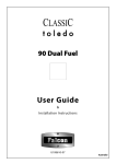
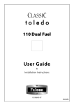
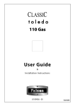
Owner’s
Manual
COOKERHOODS
CHIMNEY TYPE
CANOPY TYPE
CONTENTS
2
3
3
3
4
4
4
4
5
5
6
7
7
8
www.defy.co.za
Chimney Type
Wall Mounting
Option 1 – Recirculated Air
Option 2 – Outside Venting
Electrical Installation
Controls
Operation
Caution
Canopy Type
Cupboard Installation
Wall Mounting
Optional Rear or Top Venting
Installation
Operation
Maintenance
CHIMNEY TYPE
CAUTION
The exhaust air from the chimney hood must not be discharged into a flue or chimney
which is used for exhausting the fumes from other appliances burning gas or fuels.
Please ensure that the regulations concerning the discharge of exhaust air have been
fulfilled.
(SABS IE C60335-2-31)
All models have the ability to either re-circulate the filtered air back into the kitchen,
or to exhaust the filtered air through an outside wall or chimney pipe.
Decide on which option best suits you before commencing with the installation.
WALL MOUNTING
•
•
•
•
•
•
Remove the aluminium grease filters (perforated plates) from the base of the
hood.
The hood must be mounted directly over the cooking area. The minimum distance
between the cooking surface and the underside of the hood must be 650 mm. for
electric cookers and 750 mm. for gas burners.
Hold the body of the hood in position against the wall and mark the two keyhole
and two retaining hole positions.
Drill and fix four rawl plugs at the marked positions.
Screw suitable mounting screws into the wall at the two marked keyhole
positions.
Attach the spigot to the flange using the self tapping screws supplied.
OPTION 1 – RECIRCULATED AIR
•
•
•
•
•
Fit the T-piece to the spigot.
Fit the larger of the two chimney pieces to the main body using the four M4
screws supplied.
Lift and hang the hood and chimney assembly on the two keyhole mounting
screws.
Fit and tighten two suitable retainer screws ensuring all the while that the hood is
level.
Use the mounting bracket as a template and mark the hole positions. Drill and
attach the mounting bracket to the wall at the marked positions. Reposition the top
chimney piece so that the side holes correspond with the holes in the bracket. Fix
with two self tapping screws.
OPTION 2 – OUTSIDE VENTING
•
•
•
•
•
Do not fit the T-piece to the spigot.
Instead connect a 125 mm. diameter flexible duct straight onto the spigot flange.
Ensure that the duct vents to the outside air.
To prevent the risk of fire, do not discharge the exhaust air into a flue from other
appliances burning gas or fuel.
Fit the hood and chimney assembly as described in option 1
ELECTRICAL INSTALLATION
Connect the appliance to a 15A 230V 50 Hz earthed wall socket.
Switch off the power at the mains in the event of a fault or when cleaning the
appliance.
CONTROLS
These at located at the left front corner under the hood.
3
2
FAN
1
HOB LIGHT
OPERATION
•
•
•
•
•
Switch on the chimney hood prior to cooking.
Select the fan speed you would require depending on the type of cooking being
done.
3 for high extraction level, 2 for medium and 1 for low.
If required, you can illuminate the cooking area by switching the hood lights on.
Leave the hood running for a short period after the cooking has been completed to
clear any smoke and odours.
CAUTION
•
•
There should be adequate ventilation of the room when the chimney hood is used
at the same time as appliances using gas or other fuels.
Do not flambé under the chimney hood
CANOPY TYPE
CUPBOARD INSTALLATION
With this type of installation, (and if the rear vent is not used), the venting hole at the
top of the unit must be clear.
Remove the perforated plate underneath the unit by loosening the knurled-headed
screws on either side.
Drill four suitably spaced 5mm. diameter holes through the top of the Cooker hood.
Use these holes as a template to mark the bottom of the cupboard.
Drill four holes of 5mm diameter through the bottom of the cupboard.
Cut a hole in the in the bottom of the cupboard for the power cord to pass through.
Attach the unit to the cupboard using four 25mm long M4 screws and nuts.
Replace the perforated plate.
Plug into a 220V 50Hz earthed wall socket.
The Cooker hood is now ready for use.
WALL MOUNTING
Remove the filters so that the interior of the cooker hood and the
keyhole slots are exposed.
Hold the cooker hood in position against the wall and with a pencil
mark out the location of the keyhole slots on the wall.
Using a masonry bit, drill a hole at the top of each marked slot.
Insert a rawl plug into each hole.
Using pan-head screws with a head diameter slightly smaller than the
bottom opening of the keyhole slot, insert the screws part way into the
rawl plugs.
Leave about 5 mm of the screws proud of the wall to clear the locking
tabs
Position the keyhole slots over the screw heads and hang the cooker
hood from the screws
Tighten the screws.
To prevent the accidental lifting of the cooker hood, flatten the upright
locking tabs, adjacent to each slot.
This will prevent the cooker hood from being accidentally bumped off
the screws.
5 mm
WALL
All models can re-circulate air or vent it through an outside wall. Select the venting
mode before installing the cooker hood.
OPTIONAL REAR OR TOP VENTING INSTALLATION
When using the external venting mode, ensure that there is adequate ventilation of the
room when the Hood is used above a gas or fuel burning appliance.
Exhaust air must not be directed into a flue or chimney which is also used to extract
fumes from a gas or fuel burning appliance.
Because there is little demand for the external venting feature, we have not supplied
the necessary kit (flexible ducting and spigots) with the cooker hood. Advice is
available from: A.I.E. (PTY) LTD. P.O. BOX 490. MORNINGSIDE. 2057. TEL.
(011) 908-2544. They will be pleased to help you.
OPERATION
•
•
•
•
Switch on the Cooker hood fan as soon as cooking commences and leave it
running for about 15 minutes after the cooking is finished. This will clear the
kitchen of any excess smoke and odours.
Choose the fan speed to give the extraction level needed for the cooking
conditions. (Note: Gemini Cooker hoods have independent dual controls for left
and right hand sides)
The indicator light will illuminate when the Hood is switched on. An independent
switch operates the hob illumination light.
Important: Never flambé under the Cooker hood as an open flame could
cause a fire hazard.
MAINTENANCE
•
•
•
•
•
•
•
The Grease filter is located immediately above the perforated plate and is held in
place by metal strips.
The Grease filter must be washed every month in a solution of lukewarm water
and washing liquid to remove accumulated grease and fats. Allow the filter to dry
and re-fit it.
Replace the Grease filter by a new one when washing is no longer effective.
Replace the carbon filter by a new one when odour absorption is no longer
effective. Carbon filters can be removed by gently turning them anti-clockwise. (
as seen from the bottom ) Depending on usage the life span of Carbon filters is
approximately 2 years.
For Gas hobs, it is recommended that the Fibre filter be replaced by an
Aluminium one.
Replacement Carbon, Grease and Aluminium filters are available as spare parts
from DEFY SERVICE CENTRES country wide or by mail order.
Filters will have a longer life if they are cleaned regularly.
Important: An excessively saturated filter could become a fire hazard if not
cleaned regularly
TO MAINTAIN THE EFFECTIVENESS OF THE COOKER HOOD IT IS
ESSENTIAL THAT FILTERS BE CLEANED REGULARLY AND REPLACED
BY NEW ONES WHEN NECESSARY.