1
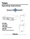
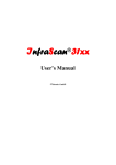
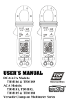
® ® A SUBSIDIARY OF C&D TECHNOLOGIES Single Output USQ 20A Models OBSOLETE PRODUCT High-Density, Quarter-Brick 20 Amp, DC/DC Converters Contact Factory for Replacement Model Features Standard, 1.45" x 2.28" x 0.40" quarter-brick package and pinout Outstanding thermal-derating Output current: to 20 Amps Outputs Voltages: 1.2/1.5/1.8/2.5/3.3/5/12/15/18/24V Input voltage ranges: 36-75V (48V nom.) 18-36V (24V nom.) Synchronous rectification yields high efficiency (to 91%) and stable no-load operation On/Off control, trim and sense functions Fully isolated, 1500Vdc guaranteed Fully I/O protected; Thermal shutdown UL1950/EN60950 (BASIC insulation) approvals Qual tested; HALT tested; EMI compliant For low-voltage, high-current power . . . in the smallest space . . . over the widest temperature range . . . call on DATEL’s USQ Series 20 Amp "quarter bricks." Occupying the industry-standard package (1.45" x 2.28" x 0.40") and pinout, USQ’s house their fully-synchronous, forward design topology in a "two-board" assembly crowned with a heat-sink-compatible aluminum baseplate. This combination of outstanding thermal and electrical efficiencies endows USQ’s with industry-leading, thermalderating performance. The 1.8VOUT model, for example, delivers its full 20 Amps up to +55°C with a mere 200 lfm air flow. USQ’s achieve all the performance metrics required for contemporary, on-board power processing: high isolation (1500Vdc), superior efficiency (to 91%), tight regulation (to ±0.05% max. line and load), low noise (to 50mVp-p), quick step response (200µsec), and an array of protection features. I/O protection includes input undervoltage lockout and reverse-polarity protection, as well as output overvoltage protection, current limiting, short-circuit protection, and thermal shutdown. The USQ functionality suite includes remote on/off control (positive or negative polarity), output trim (+10/–20%), and output sense functions. All USQ DC/DC’s are designed to meet the BASIC insulation requirements of UL1950 and EN60950, and all 48 Volt models will carry the CE mark. Safety certifications, as well as EMC compliance testing and qualification testing (including HALT) have been successfully completed. Contact DATEL for copies of the latest reports. +SENSE (7) +VOUT (8) +VIN (3) SWITCH CONTROL –VOUT (4) –VIN (1) –SENSE (5) PWM CONTROLLER REMOTE ON/OFF CONTROL* (2) INPUT UNDERVOLTAGE, INPUT OVERVOLTAGE, AND OUTPUT OVERVOLTAGE COMPARATORS OPTO ISOLATION REFERENCE & ERROR AMP VOUT TRIM (6) * Can be ordered with positive (standard) or negative (optional) polarity. Figure 1. Simplified Schematic DATEL, Inc., Mansfield, MA 02048 (USA) · Tel: (508)339-3000, (800)233-2765 Fax: (508)339-6356 · Email: [email protected] · Internet: www.datel.com USQ Series 20A, SINGLE OUTPUT DC/DC CONVERTERS Performance Specifications and Ordering Guide ➀ Input Output R/N (mVp-p) ➂ Load ➃ VIN Nom. (Volts) ➄ Range (Volts) ➄ IIN ➅ (Amps) Efficiency Package (Case, Pinout) ±0.05% ±0.05% ±0.05% ±0.05% ±0.05% ±0.05% ±0.05% ±0.05% ±0.05% ±0.05% ±0.05% ±0.05% ±0.05% ±0.05% ±0.05% ±0.05% ±0.01% 48 48 48 48 48 24 48 24 24 48 24 48 24 48 24 48 48 36-75 36-75 36-75 36-75 36-75 18-36 36-75 18-36 18-36 36-75 18-36 36-75 18-36 36-75 18-36 36-75 36-75 0.63/0.87 0.75/1.03 0.88/1.23 1.18/1.62 1.54/2.1 5.07/6.21 2.33/3.13 4.95/6.60 4.61/6.08 2.30/2.41 4.65/6.14 2.30/2.42 5.05/6.17 2.30/2.42 5.05/6.17 2.27/3.18 2.27/3.03 80% 85% 85% 87% 89% 90% 90% 87.5% 90% 90% 91% 91% 91% 91% 92% 92% 94.5% C33, P32 C33, P32 C33, P32 C33, P32 C33, P32 C33, P32 C33, P32 C33, P32 C33, P32 C33, P32 C33, P32 C33, P32 C33, P32 C33, P32 C33, P32 C33, P32 C33, P32 Regulation (Max.) Model VOUT ➁ (Volts) IOUT (Amps) Typ. Max. Line USQ-1.2/20-D48 USQ-1.5/20-D48 USQ-1.8/20-D48 USQ-2.5/20-D48 USQ-3.3/20-D48 USQ-5/20-D24 USQ-5/20-D48 USQ-6.5/16-D24 ➆ USQ-12/8.3-D24 ➇ USQ-12/8.3-D48 ➇ USQ-15/6.7-D24 USQ-15/6.7-D48 USQ-18/5.6-D24 USQ-18/5.6-D48 USQ-24/4.2-D24 USQ-24/4.2-D48 USQ-48/2.1-D48 ➆ 1.2 1.5 1.8 2.5 3.3 5 5 6.5 12 12 15 15 18 18 24 24 48 20 20 20 20 20 20 20 16 8.3 8.3 6.7 6.7 5.6 5.6 4.2 4.2 2.1 25 40 50 60 70 90 90 90 135 120 140 145 145 145 115 115 115 50 65 80 75 85 125 125 125 150 140 155 175 175 175 130 130 200 ±0.05% ±0.05% ±0.05% ±0.05% ±0.05% ±0.05% ±0.05% ±0.05% ±0.05% ±0.05% ±0.05% ±0.05% ±0.05% ±0.05% ±0.05% ±0.05% ±0.01% OBSOLETE PRODUCT Contact Factory for Replacement Model ➀ Typical at TA = +25°C under nominal line voltage and full-load conditions, unless otherwise noted. All models are tested and specified with external output capacitors (1µF ceramic in parallel with 10µF tantalum). ➁ Contact DATEL for fixed output voltages (such as 2, 6.5, –5.2V) or higher output currents (such as 12V @ 12.5A) other than those listed. ➂ Ripple/Noise (R/N) is tested/specified over a 20MHz bandwidth. Output noise may be further reduced with the installation of additional external output filtering. See I/O Filtering, Input Ripple Current, and Output Noise for details. ➃ The load-regulation specs apply over the 0-100% range. All models in the USQ Series have no minimum-load requirements and will regulate within spec under no-load conditions (with perhaps a slight increase in ripple/noise). Additionally, 1.2V, 1.5V, 1.8V, 2.5V and 5V models are unconditionally stable, including start-up and short-circuit-shutdown situations, with capacitive loads up to 25,000µF. The 12V,15V,18V and 24V models are unconditionally stable with capacitive loads up to 470µF at full load. ➄ Contact DATEL for VIN ranges other than those listed. ➅ The two listed dc currents are for the following conditions: full load/nominal input voltage and full load/low line voltage. The latter is usually the worst-case condition for input current. ➆ Contact DATEL for availability and further information on these models. ➇ These models are discontinued. Refer to DATEL's ULQ and UVQ series for alternate models. PA R T N U M B E R S T R U C T U R E U SQ - 3.3 / 20 - D48 N D Negative Trim: Contact DATEL Output Configuration: U = Unipolar/Single Remote On/Off Control Polarity: Add "P" for positive polarity (pin 2 open = converter on) Add "N" for negative polarity (pin 2 open = converter off) Quarter-Brick Package Nominal Output Voltage: 1.2/1.5/1.8/2.5/3.3/5/12/15/18/24 Volts Maximum Rated Output Current in Amps Input Voltage Range: D48 = 36-75 Volts (48V nominal) D24 = 18-36 Volts (24V nominal) M E C H A N I C A L S P E C I F I C AT I O N S 2.28 (57.91) A 2.28 (57.91) BAR CODE AND SERIAL NUMBER APPLIED TO THIS SURFACE. MODEL NUMBER ON OPPOSITE SURFACE. 0.40 MAX. (10.16) PINS 1-3, 5-7: 0.040 ±0.001 (1.016 ±0.025) PINS 4, 8: 0.062 ±0.001 (1.575 ±0.025) 2.00 (50.80) A 1.860 (47.24) A 3 0.300 (7.62) 4 5 6 7 1.45 (36.83) 2 Case C33 (4) 0.170 DIA. #M3 THD. THRU WITH 0.090 THREAD RELIEF 1.03 1.45 (26.16) (36.83) OPEN-FRAME, CAST ALUMINUM CASE B 0.600 (15.24) 1.03 (26.16) 1 Optional Heat Sink 0.15 MIN (3.81) B B B STANDOFF 0.015 (0.38) 1.860 (47.24) 8 BOTTOM VIEW DIMENSIONS ARE IN INCHES (MM) ➀ DATEL conforms to industry-standard quarter-brick pinout (see Figure 20). ➁ A "baseplate only" model with a maximum height of 0.375" (9.53mm) is 0.600 (15.24) 4 EQ. SP. @ 0.150 (3.81) I/O Connections Pin Function P32 1 –Input 2 Remote On/Off* 3 +Input 4 –Output 5 –Sense 6 Output Trim 7 +Sense 8 +Output * The Remote On/Off can be provided with either positive (standard) or negative (optional) polarity. available with the addition of an "H" suffix. Contact DATEL. 2 0.140 DIA. (3.56) (4 PLACES) * MATERIAL: BLACK ANODIZED ALUMINUM 0.10 (2.54) * USQ SERIES HEATSINKS ARE AVAILABLE IN 3 HEIGHTS: 0.25 (6.35), 0.50 (12.70) AND 1.00 (25.4) Heat Sink Ordering Information Heat Sink Height 0.25 inches (6.35mm) 0.50 inches (12.70mm) 1.00 inches (25.40mm) DATEL Part Number HS-QB25 HS-QB50 HS-QB100 All heat sinks include 4 mounting screws and a thermal pad. If using heatsinks other than DATEL's HS-QB series, the screw length should accomodate the 0.090 thread relief. USQ Models 20A, SINGLE OUTPUT DC/DC CONVERTERS Performance/Functional Specifications Typical @ TA = +25°C under nominal line voltage and full-load conditions, unless noted. Output (Continued) (1) Overvoltage Protection: 1.5VOUT 1.8VOUT 2.5VOUT 3.3VOUT 5VOUT 12VOUT 15VOUT 18VOUT 24VOUT Input Input Voltage Range: D24 Models D48 Models 18-36 Volts (24V nominal) 36-75 Volts (48V nominal) Overvoltage Shutdown None (3) Start-Up Threshold: D24 Models D48 Models 15.5-18 Volts (16.5V typical) 28.5-32 Volts (30V typical) (4) Dynamic Characteristics Undervoltage Shutdown: (4) D24 Models D48 Models Input Current: Normal Operating Conditions Inrush Transient Standby Mode: Off, UV, Thermal Shutdown 14.5-16.5 Volts (15.5V typical) 26.5-29.5 Volts (28.3V typical) Dynamic Load Response (11) See Ordering Guide 0.05A2 sec maximum Start-Up Time: (4) (12) VIN to VOUT On/Off to VOUT Calculated MTBF: 1 minute duration, 5A maximum Remote On/Off Control (Pin 2): (6) Positive Logic ("P" Suffix Models) No load Maximum Capacitive Loading (7) 25,000µF VOUT Accuracy (Full Load): Initial Temperature Coefficient Extreme (8) ±1% maximum ±0.02% per °C ±3% VOUT Trim Range (9) +10%, –20% Remote Sense Compensation (4) +10% Ripple/Noise (20MHz BW) See Ordering Guide Line/Load Regulation See Ordering Guide Efficiency See Ordering Guide Isolation Voltage: Input-to-Output Input-to-Case Output-to-Case 1500Vdc minimum 1500Vdc minimum 1500Vdc minimum Isolation Resistance 100MΩ Isolation Capacitance 650pF Current Limit Inception (90% VOUT) (10) 1.2VOUT 1.5, 1.8, 2.5, 3.3, 5VOUT 12VOUT 15VOUT 18VOUT 24VOUT 22-30 Amps (26A typical) 22-29 Amps (26A typical) 9.2-10.5 Amps (9.9A typical) 7.6-8.9 Amps (8.25A typical) 6-7.75 Amps (6.5A typical) 4.8-6 Amps (5.5A typical) Short Circuit: (4) Current Duration Hiccup Continuous (4) (14) Model and air flow dependent To +110°C (baseplate) (4) (14) +110°C +115-122°C, +118°C typical. Physical Output Minimum Loading >2.5 million hours (13) Baseplate Temperature: Maximum Allowable Thermal Shutdown On = open, open collector or 2.5-5V applied. IIN = 150µA max. Off = pulled low to 0-0.8V IIN = 800µA max. On = pulled low to 0-0.8V IIN = 800µA max. Off = open, open collector or 2.5-5V applied. IIN = 150µA max. Negative Logic ("N" Suffix Models) (11) Operating Temperature (Ambient): Without Derating With Derating Pi (0.01µF - 1.5µH - 3.3µF) Pi (0.01µF - 4.7µH - 3.3µF) (3) 5msec typical, 8msec maximum 5msec typical, 8msec maximum Environmental 5mAp-p Internal Input Filter Type: D24 Models D48 Models See Dynamic Load Response under Technical Notes Switching Frequency 3mA Input Reflected Ripple Current (5) Reverse-Polarity Protection Magnetic feedback 2.2 Volts 2.7 Volts 3.8 Volts 4.9 Volts 6.4 Volts 15 Volts 20 Volts 22.5 Volts 30 Volts (4) Dimensions 1.45" x 2.28" x 0.40" (36.8 x 57.9 x 10.2mm) Case Material Cast aluminum Baseplate Material Aluminum Shielding Neither the aluminum case nor baseplate are connected to a package pin Pin Material Brass, solder coated Weight: 1.52 ounces (43 grams) Primary-to-Secondary Insulation Level Basic (1) (2) (3) (4) (5) (6) (7) (8) (9) (10) (11) (12) (13) (14) 3 All models are tested and specified with external output capacitors (1µF ceramic in parallel with 10µF tantalum), unless otherwise noted. These converters have no minimum-load require ments and will effectively regulate under no-load conditions. Contact DATEL for input voltage ranges (18-36V, 24V nominal) other than those listed. See Absolute Maximum Ratings for allowable input voltages. See Technical Notes/Performance Curves for additional explanations and details. Input Ripple Current is tested/specified over a 5-20MHz bandwidth with an external 33µF input capacitor and a simulated source impedance of 220µF and 12µH. See I/O Filtering, Input Ripple Current and Output Noise for details. The 24V input models can benefit by increasing the 33µF external input capacitance to 100µF, if the application has a high source impedance. The On/Off Control is designed to be driven with open-collector (or equivalent) logic or the application of appropriate voltages (referenced to –Input (pin 1)). See Remote On/Off Control for more details. USQ Series DC/DC converters are unconditionally stable, including start-up and short-circuitshutdown situations, with capacitive loads up to 25,000µF (470µF for 12V, 15V, 18V and 24V models at full load). Extreme Accuracy refers to the accuracy of either trimmed or untrimmed output voltages over all normal operating ranges and combinations of input voltage, output load and temperature. See Output Trimming for detailed trim equations. The Current-Limit Inception point is the output current level at which the USQ’s power-limiting circuitry drops the output voltage 10% from its initial value. See Output Current Limiting and Short-Circuit Protection for more details. See Dynamic Load Response under Technical Notes for detailed results including switching frequencies. DATEL has performed extensive evaluations of Dynamic Load Response. In addi tion to the 10µF || 1µF external capacitors, specifications are also given for 220µF || 1µF external output capacitors for quick comparison purposes. For the Start-Up Time specifications, output settling is defined by the output voltage having reached ±1% of its final value. MTBF’s are calculated using Telcordia (Bellcore) Method 1 Case 3, ground fixed conditions, +40°C case temperature, and full-load conditions. Contact DATEL for demonstrated life-test data. All models are fully operational and meet published specifications, including "cold start," at –40°C. USQ Series 20A, SINGLE OUTPUT DC/DC CONVERTERS impedance as highly inductive source impedance can affect system stability. In Figure 2, CBUS and LBUS simulate a typical dc voltage bus. Your specific system configuration may necessitate additional considerations. Absolute Maximum Ratings Input Voltage: Continuous: Transient (100msec) 24V models 39 Volts 50 Volts 48V models 81 Volts 100 Volts Input Reverse-Polarity Protection Input Current must be <5A. 1 minute duration. Fusing recommended. Output Current Current limited. Devices can withstand an indefinite output short circuit. On/Off Control (Pin 2) Max. Voltages Referenced to –Input (pin 1) –0.3 to +7 Volts Storage Temperature –40 to +125°C Lead Temperature (Soldering, 10 sec.) +300°C In critical applications, output ripple/noise (also referred to as periodic and random deviations or PARD) can be reduced below specified limits using filtering techniques, the simplest of which is the installation of additional external output capacitors. Output capacitors function as true filter elements and should be selected for bulk capacitance, low ESR, and appropriate frequency response. In Figure 3, the two copper strips simulate real-world pcb impedances between the power supply and its load. Scope measurements should be made using BNC connectors or the probe ground should be less than ½ inch and soldered directly to the fixture. These are stress ratings. Exposure of devices to any of these conditions may adversely affect long-term reliability. Proper operation under conditions other than those listed in the Performance/Functional Specifications Table is not implied, nor recommended. All external capacitors should have appropriate voltage ratings and be located as close to the converter as possible. Temperature variations for all relevant parameters should be taken into consideration. OS-CONTM organic semiconductor capacitors (www.sanyo.com) can be especially effective for further reduction of ripple/noise. TECHNICAL NOTES The most effective combination of external I/O capacitors will be a function of line voltage and source impedance, as well as particular load and layout conditions. Our Applications Engineers can recommend potential solutions and discuss the possibility of our modifying a given device’s internal filtering to meet your specific requirements. Contact our Applications Engineering Group for additional details. Removal of Soldered USQ's from PCB's Should removal of the USQ from its soldered connection be needed, it is very important to thoroughly de-solder the pins using solder wicks or de-soldering tools. At no time should any prying or leverage be used to remove boards that have not been properly de-soldered first. Input Source Impedance USQ converters must be driven from a low ac-impedance input source. The DC/DC’s performance and stability can be compromised by the use of highly inductive source impedances. The input circuit shown in Figure 2 is a practical solution that can be used to minimize the effects of inductance in the input traces. For optimum performance, components should be mounted close to the DC/DC converter. The 24V models can benefit by increasing the 33µF external input capacitors to 100µF, if the application has a high source impedance. +SENSE +OUTPUT –OUTPUT CBUS RLOAD COPPER STRIP Figure 3. Measuring Output Ripple/Noise (PARD) Input Overvoltage Shutdown +INPUT Standard USQ DC/DC converters do not feature overvoltage shutdown. They are equipped with this function, however. Many of our customers need their devices to withstand brief input surges to 100V without shutting down. Consequently, we disabled the function. Please contact us if you would like it enabled, at any voltage, for your application. CIN – 1 SCOPE C1 = 1µF CERAMIC C2 = 10µF TANTALUM LOAD 2-3 INCHES (51-76mm) FROM MODULE LBUS + VIN 3 C2 4 5 –SENSE All models in the USQ Series are tested/specified for input ripple current (also called input reflected ripple current) and output noise using the circuits and layout shown in Figures 2 and 3. CURRENT PROBE COPPER STRIP 8 C1 I/O Filtering, Input Ripple Current, and Output Noise TO OSCILLOSCOPE 7 –INPUT CIN = 33µF, ESR < 700mΩ @ 100kHz CBUS = 220µF, ESR < 100mΩ @ 100kHz LBUS = 12µH Start-Up Threshold and Undervoltage Shutdown Under normal start-up conditions, the USQ Series will not begin to regulate properly until the ramping input voltage exceeds the Start-Up Threshold. Once operating, devices will turn off when the applied voltage drops below the Undervoltage Shutdown point. Devices will remain off as long as the undervoltage condition continues. Units will automatically re-start when the applied voltage is brought back above the Start-Up Threshold. The hysteresis built into this function avoids an indeterminate on/off condition at a single input voltage. See Performance/Functional Specifications table for actual limits. Figure 2. Measuring Input Ripple Current External input capacitors (CIN in Figure 2) serve primarily as energy-storage elements. They should be selected for bulk capacitance (at appropriate frequencies), low ESR, and high rms-ripple-current ratings. The switching nature of DC/DC converters requires that dc voltage sources have low ac 4 USQ Models 20A, SINGLE OUTPUT DC/DC CONVERTERS of 5 to 15 milliseconds, the PWM will restart, causing the output voltages to begin ramping to their appropriate values. If the short-circuit condition persists, another shutdown cycle will be initiated. This on/off cycling is referred to as “hiccup” mode. The hiccup cycling reduces the average output current, thereby preventing internal temperatures from rising to excessive levels. The USQ is capable of enduring an indefinite short circuit output condition. Start-Up Time The VIN to VOUT Start-Up Time is the interval between the point at which a ramping input voltage crosses the Start-Up Threshold voltage and the point at which the fully loaded output voltage enters and remains within it specified ±1% accuracy band. Actual measured times will vary with input source impedance, external input capacitance, and the slew rate and final value of the input voltage as it appears to the converter.The On/Off to VOUT Start-Up Time assumes the converter is turned off via the Remote On/Off Control with the nominal input voltage already applied. The specification defines the interval between the point at which the converter is turned on (released) and the point at which the fully loaded output voltage enters and remains within its specified ±1% accuracy band. Thermal Shutdown USQ converters are equipped with thermal-shutdown circuitry. If the internal temperature of the DC/DC converter rises above the designed operating temperature (See Performance Specifications), a precision temperature sensor will power down the unit. When the internal temperature decreases below the threshold of the temperature sensor, the unit will self start. On/Off Control Output Overvoltage Protection The primary-side, Remote On/Off Control function (pin 2) can be specified to operate with either positive or negative polarity. Positive-polarity devices ("P" suffix) are enabled when pin 2 is left open or is pulled high (+2.5-5V applied with respect to –Input, pin 1, IIN < 150µA typical). Positive-polarity devices are disabled when pin 2 is pulled low (0-0.8V with respect to –Input, IIN < 800µA. Negative-polarity devices are off when pin 2 is high/open and on when pin 2 is pulled low. See Figure 4. The output voltage is monitored for an overvoltage condition via magnetic coupling to the primary side. If the output voltage rises to a fault condition, which could be damaging to the load circuitry (see Performance Specifications), the sensing circuitry will power down the PWM controller causing the output voltage to decrease. Following a time-out period the PWM will restart, causing the output voltage to ramp to its appropriate value. If the fault condition persists, and the output voltages again climb to excessive levels, the overvoltage circuitry will initiate another shutdown cycle. This on/off cycling is referred to as "hiccup" mode. 3 EQUIVALENT CIRCUIT FOR POSITIVE AND NEGATIVE LOGIC MODELS +5V +INPUT Input Reverse-Polarity Protection 200k If the input-voltage polarity is accidentally reversed, an internal diode will become forward biased and likely draw excessive current from the power source. If the source is not current limited (<5A) nor the circuit appropriately fused, it could cause permanent damage to the converter. 2 ON/OFF CONTROL CONTROL 200k 1 REF Input Fusing –INPUT Certain applications and/or safety agencies may require the installation of fuses at the inputs of power conversion components. Fuses should also be used if the possibility of a sustained, non-current-limited, input-voltage polarity reversal exists. For DATEL USQ Series DC/DC Converters, slow-blow fuses are recommended with values no greater than the following: Figure 4. Driving the Remote On/Off Control Pin Dynamic control of the remote on/off function is best accomplished with a mechanical relay or an open-collector/open-drain drive circuit (optically isolated if appropriate). The drive circuit should be able to sink appropriate current (see Performance Specifications) when activated and withstand appropriate voltage when deactivated. VOUT Range 1.2VOUT Models 1.5VOUT Models 1.8VOUT Models 2.5VOUT Models 3.3VOUT Models 5 to 24VOUT Models Current Limiting When power demands from the output falls within the current limit inception range for the rated output current, the DC/DC converter will go into a current limiting mode. In this condition the output voltage will decrease proportionately with increases in output current, thereby maintaining a somewhat constant power dissipation. This is commonly referred to as power limiting. Current limit inception is defined as the point where the full-power output voltage falls below the specified tolerance. If the load current being drawn from the converter is significant enough, the unit will go into a short circuit condition. See “Short Circuit Condition.” Fuse Value -D48 1.5 Amps 2.5 Amps 3 Amps 3.5 Amps 4 Amps 6 Amps Fuse Value -D24 — — — — — 10 Amps See Performance Specifications for Input Current and Inrush Transient limits. Trimming Output Voltage USQ converters have a trim capability (pin 6) that enables users to adjust the output voltage from +10% to –20% (refer to the trim equations and trim graphs that follow). Adjustments to the output voltage can be accomplished with a single fixed resistor as shown in Figures 5 and 6. A single fixed resistor can increase or decrease the output voltage depending on its connection. Resistors should be located close to the converter and have TCR's less than 100ppm/°C to minimize sensitivity to changes in temperature. If the trim function is not used, leave the trim pin open. Short Circuit Condition When a converter is in current limit mode the output voltages will drop as the output current demand increases. If the output voltage drops too low, the magnetically coupled voltage used to develop primary side voltages will also drop, thereby shutting down the PWM controller. Following a time-out period 5 USQ Series 20A, SINGLE OUTPUT DC/DC CONVERTERS Standard USQ's have a "positive trim" where a single resistor connected from the Trim pin (pin 6) to the +Sense (pin 7) will increase the output voltage. A resistor connected from the Trim Pin (pin 6) to the –Sense (pin 5) will decrease the output voltage. DATEL also offers a "negative trim" function (D suffix added to the part number). Contact DATEL for information on negative trim devices. Trim Equations USQ-1.2/20-D48 RT UP (kΩ) = RT UP (kΩ) = RT UP (kΩ) = RT UP (kΩ) = 2 ON/OFF CONTROL TRIM +INPUT 6.23(VO – 1.226) VO – 1.5 7.44(VO – 1.226) VO – 1.8 10(VO – 1.226) RT UP (kΩ) = –OUTPUT +OUTPUT +SENSE 2 ON/OFF CONTROL TRIM RT UP (kΩ) = 8 13.3(VO – 1.226) VO – 3.3 20.4(VO – 1.226) VO – 5 +INPUT 7.64 1.5 – VO –10.2 –10.2 RTDOWN (kΩ) = 9.12 1.8 – VO –10.2 RTDOWN (kΩ) = 12.26 2.5 – VO –10.2 –10.2 RTDOWN (kΩ) = 16.31 3.3 – VO –10.2 –10.2 RTDOWN (kΩ) = 25.01 5 – VO –10.2 USQ-12/8.3-D24, -D48 7 6 RT UP (kΩ) = LOAD 49.6(VO – 1.226) VO – 12 –10.2 RTDOWN (kΩ) = 60.45 12 – VO –10.2 USQ-15/6.7-D24, -D48 5 4 RT UP (kΩ) = 62.9(VO – 1.226) VO – 15 –OUTPUT –10.2 RTDOWN (kΩ) = 76.56 15 – VO –10.2 USQ-18/5.6-D24, -D48 75.5(VO – 1.226) VO – 18 –10.2 RTDOWN (kΩ) = 92.9 18 – VO –10.2 USQ-24/4.2-D24, -D48 8 7 RT UP (kΩ) = 6 LOAD 101(VO – 1.226) VO – 24 –10.2 RTDOWN (kΩ) = 124.2 24 – VO –10.2 Note: Resistor values are in kΩ. Adjustment accuracy is subject to resistor tolerances and factory-adjusted output accuracy. VO = desired output voltage. RTRIM DOWN –SENSE 3 RTDOWN (kΩ) = USQ-5/20-D24, -D48 RT UP (kΩ) = –INPUT –10.2 –10.2 VO – 2.5 Figure 5. Trim Connections To Increase Output Voltages Using Fixed Resistors 1 –1.413 RTRIM UP –SENSE 3 1.037 1.2 – VO USQ-3.3/20-D48 The Trim pin (pin 6) is a relatively high impedance node that can be susceptible to noise pickup when connected to long conductors in noisy environments. In such cases, a 0.22µF capacitor can be added to reduce this long lead effect. +SENSE RTDOWN (kΩ) = USQ-2.5/20-D48 (VOUT at pins) x (IOUT) ≤ rated output power –INPUT –1.413 USQ-1.8/20-D48 Temperature/power derating is based on maximum output current and voltage at the converter's output pins. Use of the trim and sense functions can cause output voltages to increase, thereby increasing output power beyond the USQ's specified rating, or cause output voltages to climb into the output overvoltage region. Therefore: +OUTPUT VO – 1.2 USQ-1.5/20-D48 Trim adjustments greater than the specified +10%/–20% can have an adverse affect on the converter’s performance and are not recommended. Excessive voltage differences between VOUT and Sense, in conjunction with trim adjustment of the output voltage, can cause the overvoltage protection circuitry to activate (see Performance Specifications for overvoltage limits). 1 1.308(VO – 0.793) 5 4 Figure 6. Trim Connections To Decrease Output Voltages Using Fixed Resistors 6 USQ Models 20A, SINGLE OUTPUT DC/DC CONVERTERS Trim-Up Resistance vs. Percentage Increase in Output Voltage 1 x 10⁶ 1 x 10⁷ 1 x 10⁶ RESISTANCE RESISTANCE 1 x 10⁵ 1 x 10⁵ 1 x 10⁴ 1 x10⁴ 1 x10³ 0 1 2 3 4 5 6 7 8 9 1 x10³ 10 0 1 2 3 VOUT INCREASE (%) 4 5 6 7 8 9 10 9 10 9 10 VOUT INCREASE (%) Figure 8. USQ-1.5 Trim-Up Resistance vs. % Increase VOUT Figure 7. USQ-1.2 Trim-Up Resistance vs. % Increase VOUT 1 x 10⁶ 1 x 10⁶ RESISTANCE 1 x 10⁷ RESISTANCE 1 x 10⁷ 1 x 10⁵ 1 x10⁴ 1 x 10⁵ 0 1 2 3 4 5 6 7 8 9 1 x10⁴ 10 0 1 2 3 VOUT INCREASE (%) 4 5 6 7 8 VOUT INCREASE (%) Figure 10. USQ-2.5 Trim-Up Resistance vs. % Increase VOUT Figure 9. USQ-1.8 Trim-Up Resistance vs. % Increase VOUT 1 x 10⁸ 1 x 10⁶ 1 x 10⁷ RESISTANCE RESISTANCE 1 x 10⁷ 1 x 10⁵ 1 x10⁴ 1 x 10⁶ 0 1 2 3 4 5 6 7 8 9 1 x10⁵ 10 VOUT INCREASE (%) 0 1 2 3 4 5 6 7 8 VOUT INCREASE (%) Figure 12. USQ-5 Trim-Up Resistance vs. % Increase VOUT Figure 11. USQ-3.3 Trim-Up Resistance vs. % Increase VOUT 7 USQ Series 20A, SINGLE OUTPUT DC/DC CONVERTERS Trim-Up Resistance vs. Percentage Increase in Output Voltage 1 x 10⁸ 1 x 10⁷ 1 x 10⁷ RESISTANCE 1 RESISTANCE x 108 1 x 10⁶ 1 x10⁵ 1 x 10⁶ 0 1 2 3 4 5 6 7 8 9 1 x10⁵ 10 0 1 2 3 VOUT INCREASE (%) 5 6 7 8 9 10 9 10 18 20 Figure 14. USQ-15 Trim-Up Resistance vs. % Increase VOUT Figure 13. USQ-12 Trim-Up Resistance vs. % Increase VOUT 1 4 VOUT INCREASE (%) x 108 1 1 x 107 x 108 RESISTANCE RESISTANCE 1 x 10⁷ 1 x 10⁶ 1 x10⁵ 1 x 10⁶ 0 1 2 3 4 5 6 7 8 9 1 x10⁵ 10 0 1 2 3 VOUT INCREASE (%) 4 5 6 7 8 VOUT INCREASE (%) Figure 15. USQ-18 Trim-Up Resistance vs. % Increase VOUT Figure 16. USQ-24 Trim-Up Resistance vs. % Increase VOUT Trim-Down Resistance vs. Percentage Decrease in Output Voltage 1 x 10⁵ 1 x 10⁶ RESISTANCE 1 x 10⁷ RESISTANCE 1 x 10⁶ 1 x 10⁴ 1 x10³ 1 x 10⁵ 0 2 4 6 8 10 12 14 16 18 1 x10⁴ 20 VOUT DECREASE (%) 0 2 4 6 8 10 12 14 16 VOUT DECREASE (%) Figure 17. USQ-1.2 Trim-Down Resistance vs. % Decrease VOUT Figure 18. USQ-1.5 to USQ-18 Trim-Down Resistance vs. % Decrease VOUT 8 USQ Models 20A, SINGLE OUTPUT DC/DC CONVERTERS Negative-Trim Units ("D" Suffix) Floating Outputs Standard USQ's have a "positive-trim" function, consistent with the industry standard footprints and functionality. DATEL also offers "negative-trim" USQ's designated with a "D" suffix to the part number. The negative-trim devices trim up with a single resistor tied from the Output Trim (pin 6) to the –Sense (pin 5) to increase the output voltage. A resistor connected from the Output Trim (pin 6) to the +Sense (pin 7) will decrease the ouput voltage. Since these are isolated DC/DC converters, their outputs are "floating" with respect to their input. Designers will normally use the –Output (pin 4) as the ground/return of the load circuit. You can, however, use the +Output (pin 8) as ground/return to effectively reverse the output polarity. The "negative-trim" formula values for USQ 1.2/1.5/1.8 Volt devices with a 48 Volt input and negative logic reads: Note: The Sense and VOUT lines are not internally connected to each other. Therefore, if the sense function is not used for remote regulation, the user must connect the +Sense to +VOUT and –Sense to –VOUT at the DC/DC converter pins. RTRIM = Model USQ-1.8/20-D48ND USQ-1.5/20-D48ND USQ-1.2/20-D48ND Remote Sense A – Bx ∆V ∆V Trim Up A 0.57 0.283 0.5928 B 1 0.121 3.01 USQ series converters employ a sense feature to provide point-of-use regulation, thereby overcoming moderate IR drops in pcb conductors or cabling. The remote sense lines carry very little current and therefore require a minimal cross-sectional area conductor. The sense lines, which are capacitively coupled to their respective output lines, are used by the feedback control-loop to regulate the output. As such, they are not low impedance points and must be treated with care in layouts and cabling. Sense lines on a pcb should be run adjacent to dc signals, preferably ground. In cables and discrete wiring applications, twisted pair or other techniques should be implemented. Trim Down A 0.2711 0.065 0.5686 B 1.4676 0.352 3.96 where ∆V is the absolute value of the output voltage change desired. USQ DC/DC converters will compensate for drops between the output voltage at the DC/DC and the sense voltage at the DC/DC: [VOUT(+) –VOUT(–)] – [Sense(+) –Sense (–)] ≤ 10% VOUT Contact and PCB resistance losses due to IR drops 1 –INPUT +OUTPUT +SENSE 2 7 IOUT Sense Current ON/OFF CONTROL TRIM –SENSE 3 8 6 5 LOAD Sense Return IOUT Return +INPUT –OUTPUT 4 Contact and PCB resistance losses due to IR drops Figure 19. Remote Sense Circuit Configuration Output overvoltage protection is monitored at the output voltage pin, not the Sense pin. Therefore, excessive voltage differences between VOUT and Sense, in conjunction with trim adjustment of the output voltage, can cause the overvoltage protection circuitry to activate (see Performance Specifications for overvoltage limits). Power derating is based on maximum output current and voltage at the converter’s output pins. Use of trim and sense functions can cause output voltages to increase, thereby increasing output power beyond the USQ’s specified rating, or cause output voltages to climb into the output overvoltage region. Therefore: (VOUT at pins) × (IOUT) ≤ rated output power 9 USQ Series 20A, SINGLE OUTPUT DC/DC CONVERTERS Dynamic Load Response and Switching Frequency To avoid the added cost of constantly changing test fixtures, we have verified, during our device characterization/verification testing, that 100% testing under the former conditions (the 100µF || 1µF load), which we guarantee, correlates extremely well with the latter conditions, for which we and most of our competitors simply list typicals. DATEL has performed extensive evaluations, under assorted capacitive-load conditions, of the dynamic-load capabilities (i.e., the transient or step response) of USQ Series DC/DC Converters. In particular, we have evaluated devices using the output capacitive-load conditions we use for our routine production testing (10µF tantalums in parallel with 1µF ceramics), as well as the load conditions many of our competitors use (220µF tantalums in parallel with 1µF ceramics) when specifying the dynamic performance of their devices. Load Conditions ➀ COUT = 10µF || 1µF 10µF || 1µF COUT = 220µF || 1µF If you have any questions about our test methods or would like us to perform additional testing under your specific load conditions, please contact our Applications Engineering Group. Performance Specifications 1.2VOUT 1.5VOUT 1.8VOUT 2.5VOUT 3.3VOUT 5VOUT 12 to 24VOUT Load Step = 50 to 75% of IOUT Max.: Peak Deviation, typ. Settling Time to ±1% of Final Value, max. ➁ 115mV 200µs 110mV 200µs 125mV 225µs 100mV 200µs 170mV 100µs 125mV 100µs 100mV 100µs Load Step = 75 to 50% of IOUT Max.: Peak Deviation, typ. Settling Time to ±1% of Final Value, max. ➁ 115mV 140µs 110mV 200µs 125mV 225µs 100mV 200µs 100mV 100µs 125mV 100µs 100mV 100µs Load Step = 50 to 75% of IOUT Max.: Peak Deviation, typ. Settling Time to ±1% of Final Value, typ. ➁ 120mV 115µs TBD TBD 105mV 170µs 90mV 65µs 105mV 65µs TBD TBD 85mV 40µs Load Step = 75 to 50% of IOUT Max.: Peak Deviation, typ. Settling Time to ±1% of Final Value, typ. ➁ 120mV 150µs TBD TBD 90mV 150µs 90mV 70µs 105mV 65µs TBD TBD 50mV 25µs Switching Frequency (min./typ./max. kHz) 120/150/180 120/150/180 170/185/200 230/255/280 132/147/162 220/240/260 ➀ The listed pair of parallel output capacitors consists of a tantalum in parallel with a multi-layer ceramic. ➁ ∆IO/∆t = 1A/1µs, VIN = 48V, TC = 25°C. 10 190/210/230 USQ Models 20A, SINGLE OUTPUT DC/DC CONVERTERS Typical Performance Curves for 1.2VOUT Models �������������������������������������������������������������� ��������������������������������������������������������������� USQ-1.2/20-D48 Efficiency vs. Line Voltage and Load Current 90 �� TBD TBD 80 �� �� ��������������������� Efficiency (%) 85 75 VIN = 36V 70 VIN = 48V �� ������� �� ������������������ �� �� � � VIN = 75V 65 � � 60 2 4 6 8 10 12 14 16 18 � 20 Load Current (Amps) ���� ��� ��� ��� ��� ��� ��� ��� ��� ������������������������ Start-Up from VIN (VIN = 48V, IOUT = 20A, COUT = 10µF tantalum || 1µF ceramic.) TBD TBD +Input (pin 3) 20V/div 1V/div 1.5VOUT (pin 8) 2msec/div Start-Up from Remote On/Off Control (VIN = 48V, IOUT = 20A, COUT = 10µF tantalum || 1µF ceramic.) TBD TBD 2V/div Remote On/Off Control (pin 2) 1V/div 1.5VOUT (pin 8) 2msec/div 11 ��� ��� ��� ��� �� USQ Series 20A, SINGLE OUTPUT DC/DC CONVERTERS Typical Performance Curves for 1.5VOUT Models �������������������������������������������������������������� ��������������������������������������������������������������� �������������������������������������������������������������� �� �� �� �� ��������������������� �������������� �� �� ��������� �� ��������� ������� �� ������� ������������������ �� ������� �� �� � � �� � ��������� � �� ��� �� �� �� �� ��� ��� ��� ��� ��� � ���� �� ���� �� ��� ��� ������������������� ��� ��� ��� ��� ��� ��� ��� ��� ������������������������ �������������������������������������������������������������� ����������������������������������������������������������������� Start-Up from VIN (VIN = 48V, IOUT = 20A, COUT = 10µF tantalum || 1µF ceramic.) �� �� ������� �� ��������������������� +Input (pin 3) 20V/div ������� �� ������������������ �� ������� �� �� � � 1V/div � 1.5VOUT (pin 8) � � ���� 2msec/div �� ��� ��� ��� ��� ��� ��� ������������������������ Start-Up from Remote On/Off Control (VIN = 48V, IOUT = 20A, COUT = 10µF tantalum || 1µF ceramic.) 2V/div ���� Remote On/Off Control (pin 2) 1V/div 1.5VOUT (pin 8) 2msec/div 12 ��� ��� ��� ��� USQ Models 20A, SINGLE OUTPUT DC/DC CONVERTERS Typical Performance Curves for 1.8VOUT Models �������������������������������������������������������������� ��������������������������������������������������������������� �������������������������������������������������������������� �� �� �� �� ��������������������� �������������� �� �� �� ��������� �� ��������� ������� �� ������� �� ������������������ �� ������� �� � � �� � ��������� �� ��� �� �� �� �� ��� ��� � ��� ��� ��� � ���� �� ���� �� ��� ������������������� ��� ��� ��� ��� ��� ��� ��� ��� ��� ��� ��� ������������������������ �������������������������������������������������������������� ����������������������������������������������������������������� Start-Up from VIN (VIN = 48V, IOUT = 20A, COUT = 10µF tantalum || 1µF ceramic.) �� �� ������� �� ��������������������� +Input (pin 3) 20V/div ������� �� ������� �� ������������������ �� �� � � 1V/div � 1.8VOUT (pin 8) � � ���� 2msec/div �� ��� ��� ��� ��� ��� ��� ������������������������ Start-Up from Remote On/Off Control (VIN = 48V, IOUT = 20A, COUT = 10µF tantalum || 1µF ceramic.) 2V/div ���� Remote On/Off Control (pin 2) 1V/div 1.8VOUT (pin 8) 2msec/div 13 ��� ��� USQ Series 20A, SINGLE OUTPUT DC/DC CONVERTERS Typical Performance Curves for 2.5VOUT Models �������������������������������������������������������������� ��������������������������������������������������������������� �������������������������������������������������������������� �� �� �� �� �� ��������������������� �� �������������� �� �� �� ��������� �� �� ��������� �� �� �� ������������������ � � �� �� �� ��� ��� ��� ��� ��� � �� ������������������� ���� ��� ��� ��� ��� ��� ��� ��� ��� ������������������������ Start-Up from VIN (VIN = 48V, IOUT = 20A, COUT = 10µF tantalum || 1µF ceramic.) +Input (pin 3) 20V/div 1V/div 2.5VOUT (pin 8) 2msec/div Start-Up from Remote On/Off Control (VIN = 48V, IOUT = 20A, COUT = 10µF tantalum || 1µF ceramic.) 2V/div �� � �� �� ��� �� ������� �� � ��������� �� ������� Remote On/Off Control(pin 2) 1V/div 2.5VOUT (pin 8) 2msec/div 14 ��� ��� ��� ��� �� USQ Models 20A, SINGLE OUTPUT DC/DC CONVERTERS Typical Performance Curves for 3.3VOUT Models �������������������������������������������������������������� ��������������������������������������������������������������� �������������������������������������������������������������� �� �� �� �� ��������������������� �� �������������� �� �� ��������� �� ��������� �� ��������� ������� �� ������� �� �� � ������� � �� � �� �� ������� ������� �� � ���� ���� ���� ����� ����� ����� ����� � ���� ��� ���� �� ��� ������������������� ��� ��� ��� ��� ��� ��� ��� ��� ��� ������������������������ �������������������������������������������������������������� ����������������������������������������������������������������� Start-Up from VIN (VIN = 48V, IOUT = 20A, COUT = 10µF tantalum || 1µF ceramic.) �� �� ������� �� ��������������������� +Input (pin 3) 20V/div ������� �� �� ������� ������������������ �� �� � � 3.3VOUT (pin 8) 1V/div � � � ���� ���� �� ��� 2msec/div ��� ��� ��� ��� ��� ��� ��� ��� ��� ��� ��� ������������������������ �������������������������������������������������������������� ������������������������������������������������������������������� Start-Up from Remote On/Off Control (VIN = 48V, IOUT = 20A, COUT = 10µF tantalum || 1µF ceramic.) �� �� Remote On/Off Control (pin 2) 3.3VOUT (pin 8) ��������������������� �� 2V/div ������� �� ������� �� �� �� � � 1V/div � � � ���� 2msec/div ���� �� ��� ��� ��� ��� ��� ��� ������������������������ 15 ��� ��� USQ Series 20A, SINGLE OUTPUT DC/DC CONVERTERS Typical Performance Curves for 5VOUT Models ������������������������������������������������������������ ��������������������������������������������������������������� ������������������������������������������������������������ �� �� �� �� ��������������������� �� �������������� �� �� ��������� �� ��������� �� ������� �� ������� �� ������� �� �� � ������� � ��������� �� � � �� ��� �� �� �� �� ��� ��� ��� ��� ��� � ���� �� ���� �� ��� ��� ������������������� ��� ��� ��� ��� ��� ��� ��� ��� ��� ��� ��� ��� ������������������������ ������������������������������������������������������������ ����������������������������������������������������������������� Start-Up from VIN (VIN = 48V, IOUT = 20A, COUT = 10µF tantalum || 1µF ceramic.) �� �� �� ��������������������� +Input (pin 3) 20V/div ������� �� ������� �� ������� �� �� � � 5VOUT (pin 8) 1V/div � � � ���� ���� �� ��� ��� 2msec/div ��� ��� ��� ��� ��� ��� ������������������������ Start-Up from Remote On/Off Control (VIN = 48V, IOUT = 20A, COUT = 10µF tantalum || 1µF ceramic.) ������������������������������������������������������������ ����������������������������������������������������������������� �� �� Remote On/Off Control (pin 2) 5VOUT (pin 8) ��������������������� 5V/div ������� �� ������� ������� �� �� �� �� ������������������ � � 1V/div � � � ���� 2msec/div ���� �� ��� ��� ��� ��� ��� ��� ������������������������ 16 ��� ��� USQ Models 20A, SINGLE OUTPUT DC/DC CONVERTERS Typical Performance Curves for 5VOUT Models ������������������������������������������������������������ ������������������������������������������������������������������� �� ������� �� ��������������������� �� �� �� ������� �� �� ������� � � � � � ���� ��� ��� ��� ��� ��� ��� ��� ��� ��� ��� ��� ��� �� ��� �� ������������������������ ������������������������������������������������������������ ����������������������������������������������������������������� �� ������� �� ��������������������� �� �� �� ������� �� ������� �� � � � � � ���� ��� ��� ��� ��� ��� ��� ��� ��� ������������������������ 17 ��� ��� ��� USQ Series 20A, SINGLE OUTPUT DC/DC CONVERTERS Typical Performance Curves for 12VOUT Models USQ-12/8.3-D48: Output Current vs. Ambient Temperature (Transverse air flow, pin 1 to pin 3; VIN = 48V, no heat sink.) USQ-12/8.3-D48 Efficiency vs. Line Voltage and Load Current 95 9 90 8 80 75 VIN = 36V 70 60 400 lfm 5 200 lfm 4 2.49 3.32 4.15 Natural Convection 3 2 VIN = 75V 1.66 600 lfm 6 VIN = 48V 65 55 0.83 7 Output Current (Amps) Efficiency (%) 85 1 4.98 5.81 6.64 7.47 0 8.3 20 25 30 35 Load Current (Amps) 50 55 60 65 70 75 80 85 USQ-12/8.3-D48: Output Current vs. Ambient Temperature (Longitudinal air flow, pin 1 to pin 3; VIN = 48V, no heat sink.) 10 8 Output Current (Amps) +Input (pin 3) 45 Ambient Temperature (°C) Start-Up from VIN (VIN = 48V, IOUT = 8.3A, COUT = 10µF tantalum || 1µF ceramic.) 20V/div 40 200 lfm 600 lfm 400 lfm 6 4 Natural Convection 12VOUT (pin 8) 2 5V/div 0 –40 2msec/div –10 0 10 20 30 40 50 60 Ambient Temperature (°C) The USQ Series 12V models are discontinued. These Performance Curves are for documentation purposes only. Refer to DATEL's ULQ or UVQ series for alternate models. 18 70 80 90 100 USQ Models 20A, SINGLE OUTPUT DC/DC CONVERTERS Typical Performance Curves for 12VOUT Models USQ-12/8.3-D24: Output Current vs. Ambient Temperature (Transverse air flow, pin 1 to pin 3; VIN = 24V, no heat sink.) Start-Up from Remote On/Off Control (VIN = 48V, IOUT = 8.3A, COUT = 10µF tantalum || 1µF ceramic.) 9 8 Output Current (Amps) Remote On/Off Control (pin 2) 2V/div 6 600 lfm 5 400 lfm 4 200 lfm Natural Convection 3 2 12VOUT (pin 8) 5V/div 7 1 0 20 2msec/div 25 30 35 40 45 50 9 Output Current (Amps) 8 7 6 400 lfm 4 200 lfm 3 2 1 0 20 25 30 35 40 45 50 55 60 Ambient Temperature (°C) USQ-12/8.3-D24: Output Current vs. Ambient Temperature (Transverse air flow, pin 1 to pin 3; VIN = 24V, 1/2" heat sink.) 5 55 60 65 70 75 80 85 Ambient Temperature (°C) The USQ Series 12V models are discontinued. These Performance Curves are for documentation purposes only. Refer to DATEL's ULQ or UVQ series for alternate models. 19 65 70 75 80 85 USQ Series 20A, SINGLE OUTPUT DC/DC CONVERTERS Typical Performance Curves for 15VOUT Models �������������������������������������������������������������� ��������������������������������������������������������������� �������������������������������������������������������������� � �� �� � ��������������������� �������������� �� �� �� ��������� �� �� ��������� � � �� �������� � � � ��������� ����� ����� ����� ����� ������� ������������������ �� �� ������� ����� ����� ����� ����� � ��� ���� ��� ��� ��� ������������������� ��� ��� ��� ��� ��� ��� ��� ��� ��� �� ������������������������ �������������������������������������������������������������� ����������������������������������������������������������������� Start-Up from Remote On/Off Control (VIN = 48V, IOUT = 6.7A, COUT = 10µF tantalum || 1µF ceramic.) � ��������������������� Remote On/Off Control (pin 2) 2V/div � ������� ������� � ������� ������������������ � 15VOUT (pin 8) 5V/div � ���� 2msec/div ���� �� ��� ��� ��� ��� ��� ��� ������������������������ Start-Up from VIN (VIN = 48V, IOUT = 6.7A, COUT = 10µF tantalum || 1µF ceramic.) +Input (pin 3) 20V/div 15VOUT (pin 8) 5V/div 2msec/div 20 ��� ��� ��� ��� USQ Models 20A, SINGLE OUTPUT DC/DC CONVERTERS Typical Performance Curves for 24VOUT Models �������������������������������������������������������������� ��������������������������������������������������������������� �������������������������������������������������������������� ��� �� � ��������������������� �� �������������� �� �� ��������� �� �� ��������� �� ��� ������� � ������� ������� ��� ������������������ � ��� � ��������� �� �� �������� ����� ����� ����� ���� ��� ����� ����� ����� ����� � ��� ���� ��� ��� ��� ��� ������������������� ��� ��� ��� ��� ��� ��� ��� �� ��� �� ������������������������ �������������������������������������������������������������� ��������������������������������������������������������������� �������������������������������������������������������������� ��� �� � ��������������������� �� �� �������������� ��� �� ��������� �� ��������� �� ��������� ��� � ������� ��� ������� � ������� ��� ������������������ � �� ��� �� �������� ����� ����� ����� ���� ����� ����� ����� ����� � ��� ���� ������������������� ��� ��� ��� ��� ��� ��� ��� ��� ��� ��� ��� ������������������������ Start-Up from Remote On/Off Control (VIN = 48V, IOUT = 4.2A, COUT = 10µF tantalum || 1µF ceramic.) Start-Up from VIN (VIN = 48V, IOUT = 4.2A, COUT = 10µF tantalum || 1µF ceramic.) Remote On/Off Control (pin 2) +Input (pin 3) 2V/div 20V/div 24VOUT (pin 8) 10V/div 10V/div 24VOUT (pin 8) 2msec/div 2msec/div 21 USQ Series 20A, SINGLE OUTPUT DC/DC CONVERTERS –Input –Output +Input –Sense Output Trim Remote On/Off Remote On/Off +Sense +Input +Output –Input BOTTOM VIEW +Sense Output Trim LOCATE THERMOCOUPLE HERE –Sense –Output Figure 21. Thermocouple Placement for Temperature Derating Calculations The typical derating curves on the previous pages were developed by monitoring the temperature of the case with a thermocouple placed on top of the USQ case as shown in Figure 21. Users desiring to model their own application's temperature derating for a particular environment (enclosed area, orientation, airflow, possible heatsinking) should make sure the case temperature does not exceed 110°C for any condition. Figure 20 readily allows users to confirm that DATEL quarter-brick DC/DC converters are compatible to the industry-standard pinout, independent of pin-numbering conventions. DATEL (UK) LTD. Tadley, England Tel: (01256)-880444 Internet: www.datel-europe.com E-mail: [email protected] ® DATEL S.A.R.L. Montigny Le Bretonneux, France Tel: 01-34-60-01-01 Internet: www.datel-europe.com E-mail: [email protected] A SUBSIDIARY OF C&D TECHNOLOGIES DATEL, Inc. 11 Cabot Boulevard, Mansfield, MA 02048-1151 Tel: (508) 339-3000 (800) 233-2765 Fax: (508) 339-6356 www.datel.com Email: [email protected] www.cdpowerelectronics.com ISO 9001 REGISTERED +Output TOP VIEW Figure 20. Industry Standard Quarter-Brick Pinout ® X DS-0493D 10/04 DATEL GmbH München, Germany Tel: 89-544334-0 Internet: www.datel-europe.com E-mail: [email protected] DATEL KK Tokyo, Japan Tel: 3-3779-1031, Osaka Tel: 6-6354-2025 Internet: www.datel.co.jp Email: [email protected], [email protected] DATEL China Shanghai, China Tel: 011-86-51317131 E-mail: [email protected] DATEL makes no representation that the use of its products in the circuits described herein, or the use of other technical information contained herein, will not infringe upon existing or future patent rights. The descriptions contained herein do not imply the granting of licenses to make, use, or sell equipment constructed in accordance therewith. Specifications are subject to change without notice. The DATEL logo is a registered DATEL, Inc. trademark. 22