1
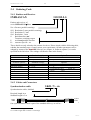
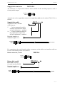
InfraScan31xx User’s Manual (Sitronic GmbH) INFRASCAN3100 3 Manual Contents 1. 1.1 1.1.1 1.1.2 1.2 1.3 1.4 DESCRIPTION ............................................................................................................ 4 Working Principle .......................................................................................................... 4 Parallel Scanning ............................................................................................................ 4 Double scanning (enhanced resolution) ......................................................................... 6 System Description and Definitions ............................................................................... 7 Maintenance ................................................................................................................... 7 Scope of Supply.............................................................................................................. 8 2. 2.1 2.2 2.3 2.4 2.4.1 2.4.2 PRODUCT SELECTION ............................................................................................ 8 Smallest Detectable Object Size and Cycle Time .......................................................... 9 Measuring Accuracy and Cycle Time ............................................................................ 9 Distance Ranges ........................................................................................................... 10 Ordering Code .............................................................................................................. 11 Emitter and Receiver .................................................................................................... 11 Cables and Connectors ................................................................................................. 11 3. 3.1 3.2 3.3 3.3.1 3.3.2 3.4 3.4.3 3.5 3.5.1 3.5.2 3.5.3 MOUNTING and COMMISSIONING .................................................................... 13 Mechanical Measures ................................................................................................... 13 Electrical Connection ................................................................................................... 14 Measuring Distance and Adjusting .............................................................................. 15 Defined Measuring Distance ........................................................................................ 15 Self Calibration............................................................................................................. 15 How to Earth the System .............................................................................................. 16 Power Supply ............................................................................................................... 18 Hints for Use ................................................................................................................ 18 Reflections .................................................................................................................... 18 Influence of Ambient Light .......................................................................................... 20 Over-modulation of Receiver ....................................................................................... 20 4. 4.1 4.2 4.3 4.4 4.5 4.6 4.6.1 4.6.2 4.6.3 4.7 4.8 4.9 SOFTWARE OPTIONS ............................................................................................ 21 Setting of Measuring Distance ..................................................................................... 21 Special Settings ............................................................................................................ 22 Active Scan Area .......................................................................................................... 23 Valid Data (Threshold) ................................................................................................. 24 Smoothing .................................................................................................................... 24 Output Formats ............................................................................................................. 26 DATA/POSITION - normal ......................................................................................... 26 DATA/POSITION - over all ........................................................................................ 27 DATA/POSITION - largest blocked area .................................................................... 27 Output Modes and Coding............................................................................................ 28 Remote Diagnosis (Error Messages) ............................................................................ 28 Original Configuration ................................................................................................. 28 5. 5.1 5.2 5.3 4.1.1 4.1.2 OUTPUTS, EVALUATION ...................................................................................... 29 Serial Interface with UART ......................................................................................... 29 Switching Output and Power Supply ........................................................................... 35 Parallel Interface and Power Supply ............................................................................ 36 Synchronization using DATA-READY Signal:........................................................... 37 Freezing Data Records using HOLD Control Line: ..................................................... 37 6. TECHNICAL DATA.................................................................................................. 38 7. APPENDIX A ............................................................................................................. 40 Sitronic INFRASCAN3100 1. 4 Manual DESCRIPTION 1.1 Working Principle The INFRASCAN31xx Series photoelectric light curtains are electronic precision measurement instruments, which operate on the basis of infrared light beams. Each measuring system comprises two casings, one containing the emitters the other the receivers together with the electronics for light pulse and data output control. 1.1.1 Parallel Scanning Together with the facing receivers, the infrared LEDs, which are lined up next to one another inside the emitter unit, form a grid of absolutely parallel beams. This principle permits the recognition and measurement of all objects, which attenuate infrared light or are impervious to it. The surface of the object or the distance between the emitter and receiver has no effect on the measurement. Emitter Receiver First beam Last beam To perform the measurement, the individual infrared LED’s are activated in succession and the associated receivers are scanned at the same time. In other words, light beam "1" is interrupted at the moment the imaginary line from emitter "1" to receiver "1" is interrupted, since only the first receiver is scanned at the moment the first light beam is transmitted. This also applies accordingly to the following beams, resulting in the formation of a "light grid" comprising invisible light beams arranged in parallel to one another. As only the associated receiver of each infrared LED is activated, wide-angle radiation is possible. The conical light beams ensure fault-free operation of the INFRASCAN photoelectric barriers, even if they are exposed to severe vibration, which greatly simplifies adjustment when mounted. Receiver Emitter Sitronic INFRASCAN3100 5 Manual As a standard, up to 64 beams are available, depending on the resolution (spacing between the beams) The best resolution is 2.0 mm. This is equivalent to a measuring or detecting range (i.e. distance between first and last beam) of 120 mm respectively. Scanners with resolution of 2.5 mm and 5 mm are also available. In short, the measurement procedure can be described as follows: EMITTER RECEIVER 2nd beam EMITTER Since the individual light beams are parallel to one another, it is of no relevance to the measurement result whether the object is closer to the transmitter or the receiver. RECEIVER Assuming that an object is located within the measuring range of the scanner, the individual beams are activated in succession during a measuring cycle as described previously. The number of interrupted beams is indicative of the size of the test object. The measured value is provided as DATA, representing the number of broken beams. In addition, the number of the first interrupted beam – and hence the position of the test object – can be output as the „POSITION“ parameter. 1st beam Although certain defects, e.g. broken cables or defects occurring in electronic components, will lead to an output signal, these light curtains are not „self protecting“. 4th beam EMITTER 3rd beam EMITTER The system's high clock frequency contributes to a high measuring accuracy or short response time respectively. This is all the more important the quicker the target object is moved through the scanner and the more variable its shape is. Objects moving through the scanner at high speed can be detected more easily. In other words, objects passing the scanner could be smaller and faster and still be detected. RECEIVER As applies for measuring objects, the value for the smallest detectable object size does not vary over the whole measuring range. RECEIVER If the scanner is used for detection purposes (to detect whether an object is present within the measuring range), the smallest detectable object size is of interest. This is dependant on the object moving horizontally or vertically to the scanner. Please note that these light curtains are not designed for safety applications! Sitronic INFRASCAN3100 6 Manual The INFRASCAN31xx series can be operated at temperatures ranging form -25°C .. + 55°C. The aluminium housing which meets the requirements of protection class IP67, together with the high immunity to external light sources makes the INFRASCAN31xx very suitable for service in the open and in adverse conditions. Please note, however, that all cables must be connected to guarantee that the plugs are water tight. 1.1.2 Double scanning (enhanced resolution) For some applications a higher measuring accuracy or improved capability to detect very small objects may be desirable. For this purpose the function „double scanning“ or „enhanced resolution“ is available. The method used is to insert an additional beam, as it were, diagonally between the parallel beams. The first beam runs, as with parallel scanning, from transmitter „1“ to receiver „1“, the second beam, however, from transmitter „2“ to receiver „1“, the third beam from transmitter „2“ to receiver „2“ (i.e. is parallel again), and so forth. If we call np the number of beams for parallel scanning, then the number of beams nd for double scanning can be calculated by means of the formula nd = 2 np - 1, i.e. 32 beams would result in 63 beams with a resolution of 1,27 mm (as against 2,54 mm for parallel scanning). r/2 r EMITTER RECEIVER First beam Last beam Measuring distance It should be noted, however, that this doubled resolution, as well as the corresponding smallest detectable object size, only apply to the centre of the measuring distance (between transmitter and receiver). Sitronic INFRASCAN3100 7 Manual 1.2 System Description and Definitions Looking at the measuring system as shown below, with the transmitter mounted on the right and the receiver on the left, the top beam is designated the first measuring beam and the bottom one is designated the last measuring beam, according to the sequence of scanning. First beam Oy EMITTER DATA Sensing area Lm RECEIVER POSITION y x Last beam Indicating LEDs below the last beam Measuring distance Oz z The optically active area is designated the measuring area, the number of interrupted beams is output as DATA. Alternatively, if required, the number of the first interrupted measuring beam is output and designated as POSITION. By definition, the last beam is situated at the end nearer to the connecting sockets. The distance between emitter and receiver is designated the measuring distance. The object size is named Oy and the difference to DATA is the measuring deviation. It must be distinguished between the maximum possible deviation for a single measurement and the average deviation over a number of measurements. The minimum detectable object size is different in the y- and z-axis. Therefore it must be distinguished between two values which are defined as Oy min and Oz min. Both transmitter and receiver are equipped with indicating LEDs. Their function is described in chapter 3.2. 1.3 Maintenance The INFRASCAN31xx light curtains require practically no maintenance. Occasionally, particularly if one or more beams are dark because of soiled windows (which will be indicated by a flashing green LED on the receiver), just wipe the window surface with a soft cloth, if necessary use warm water or a mild detergent. Avoid scratching tools, hot water or steam. Sitronic INFRASCAN3100 8 Manual 1.4 Scope of Supply The INFRASCAN31xx measuring/detecting system comprises the following components: 1. 2. 3. 4. Emitter with sockets for synchronization and power supply, Receiver with sockets for synchronization, data output serial and switching or parallel data output, Synchronization cable (connecting emitter and receiver), Supply/data connector for power supply and/or parallel data output (alternatively supply/data cable). Optionally is available: 5. 6. 7. 8. 2. Data connector or data cable for the serial interface (optionally as interface cable1), Supply/data cable for the parallel interface or the switching output, Interface cable INFRASCAN3100 - RS422 / RS232 – PC, if „after delivery“ programming of the scanner is desired, or alternatively Interface cable INFRASCAN3100 - RS422 / USB2. PRODUCT SELECTION Depending on the application different demands on the scanner will be in the foreground. In most cases these will be the decisive criteria: 1. Using it either as a detecting or a measuring scanner will determine the kind of output. The choice can be made between a transistor switching output or a parallel data output. 2. Measuring area: Will be determined by the variation in size and position of the measuring object. Standard units and their measuring ranges are listed in the following tables. 3. Resolution: Basically the series INFRASCAN31xx offers 3 different beam spacings, namely 5, 2.5 and 2 mm at parallel scanning (2.5, 1,25 and 1 mm respectively at double scanning). Larger beam spacing can be offered upon request. Directly connected to the resolution is the smallest detectable object size Oy min. In case that objects move perpendicular through the light curtain (e.g. are falling through a horizontally mounted scanner) and have to be detected, the cycle or switching time respectively is of great importance. The following tables show the static values (object not moving). Practically identical to the smallest detectable object size Oy min is the maximum measuring deviation for a single measurement. This value will be cut to half when the measuring objects always move on the same level (e.g. on a conveyor belt). For continuous measuring usually the average measuring accuracy is of interest. The following tables show the arithmetic mean calculated over 10 measurements. 1 2 This cable can be ordered in any length. This cable presently is only available in 2 m length. Sitronic INFRASCAN3100 9 Manual The following tables show the light curtains of the series INFRASCAN31xx which are available as standard. For special applications which cannot be covered by these standard units certain modifications can be made. Please contact manufacturer. 2.1 Smallest Detectable Object Size and Cycle Time Type No. of beams 3116/05.0 3132/05.0 3132/02.5 3164/02.5 3132/02.0 3164/02.0 3116/05.0D 3132/05.0D 3132/02.5D 3164/02.5D 3132/02.0D 3164/02.0D 16 32 32 64 32 64 31 63 63 127 63 127 Resolution M. area r [mm] Lm [mm] 5,0 5,0 2,5 2,5 2,0 2,0 2,5** 2,5** 1,25** 1,25** 1,0** 1,0** Oy min [mm]* Oz min [mm]* Cycle time [ms] 7,5 7,5 4,0 4,0 3,5 3,5 4,0** 4,0** 3,0** 3,0** 2,5** 2,5** 4,5 4,5 2,5 2,5 2,5 2,5 4,5 4,5 2,5 2,5 2,5 2,5 0,84 0,84 0,84 0,84 0,84 0,84 0,84 0,84 0,84 1,47 0,84 1,47 75 155 77,5 157,5 62 126 75 155 77,5 157,5 62 126 * Can only be guaranteed when the measuring distance corresponds to the preset value (not adjusted by self-calibration) ** In the centre of the measuring distance. 2.2 Measuring Accuracy and Cycle Time Type No. of beams Resolution M. area M.deviation r [mm] Lm [mm] single mmt. max. [mm]* 3116/05.0 16 5,0 75 7,5 3132/05.0 3132/02.5 3164/02.5 3132/02.0 3164/02.0 3116/05.0D 32 32 64 32 64 31 5,0 2,5 2,5 2,0 2,0 2,5** 155 77,5 157,5 62 126 75 7,5 4,0 4,0 3,5 3,5 4,0** 3132/05.0D 3132/02.5D 3164/02.5D 3132/02.0D 3164/02.0D 63 63 127 63 127 2,5** 1,25** 1,25** 1,0** 1,0** 155 77,5 157,5 62 126 4,0** 3,0** 3,0** 2,5** 2,5** meas. accuracy [mm]*** Cycle time [ms] 1,5 1,5 0,5 0,5 1,2 1,2 0,84 1,5 1,5 0,5 0,5 1,2 1,2 0,84 0,84 0,84 0,84 0,84 0,84 0,84 0,84 1,47 0,84 1,47 * Measuring range „free“ on both ends of the object. If POSITION is output or when the scanner is used for “height” measurement, only half the value applies. ** In the centre of the measuring distance. *** Arithmetic mean calculated over 10 measurements. Sitronic INFRASCAN3100 10 Manual 2.3 Distance Ranges Due to the fact that the scanners are used at different measuring distances, the signal strengths have to be adapted accordingly in order to ensure correct operation of the receiver amplifier. This can either be done by means of the ScanView software via the serial interface, as described in chapter 4.1 or by means of the Self-calibration function as described in chapter 3.3.2. In case a defined object detection at a certain measuring distance is required, this has to be specified. The scanner will be adapted specially and a customer specific identification needs to be issued. Depending on the scanner type the following standard distance ranges apply: Resolution 5 mm and more: Resolution 2.5 mm und 2.0 mm: 0.2 ... 6.0 m (32 ranges) 0.05 ... 1.7 m (32 ranges). A diagram of the distance ranges can be found in chapter 4.1 Setting of measuring distance. As the setting of gain is influenced by both the receiver and the transmitter, we recommend: Always combine transmitters and receivers with the same serial number ! Sitronic INFRASCAN3100 11 Manual 2.4 Ordering Code 2.4.1 Emitter and Receiver INFRASCAN 3132/02.5-S Emitter and receiver of series INFRASCAN31xx No. of beams (parallel scanning) 05.0 Resolution 5 mm (parallel scanning), 02.5 Resolution 2.5 mm 02.0 Resolution 2 mm S Serial interface and Transistor switching output P serial and parallel interface K... customer specific ..no. These details are only related to the scanner hardware. Please check with the following table, whether the standard scope of supply meets your requirement. All other parameters can be adapted by means of the ScanView software (see chapter “4. Software options”) or can be specified in the list below. The settings will then be done in the factory. Accessories Synchronization cable Supply cable Standard supply 5m See chapter 2.4.2 Software options Scanning method Measuring distance Data format Coding Output mode SMOOTHING Active scan area Valid data value Options3 ...........m4 See chapter 2.4.2 Standard settings Options Parallel scanning 0,1 – 0,7 m NORMAL BINARY Number of beams 1 First und Last LED Offset: 0 Low: 0 High: 65535 Double scanning ...... m Largest Blocked Area OVER ALL GRAY BCD mm ……. First LED Offset …. Last LED Offset …. Low: ….. High: .......... 2.4.2 Cables and Connectors Synchronization cable SK31-7/... m Synchronization cable, shielded Required length in m Standard length is 5 m 7-pins male 7 pins male l One synchronization cable is part of the standard delivery, as well as … 3 4 Please tick where applicable. For cables longer than 5 m there is a surcharge. Sitronic INFRASCAN3100 12 Manual AS31-14 Supply/data connector The connector is a 14-pin male connector and is suitable for the switching output, as well as for the parallel output. 14 pins male Alternatively to the supply/data connector a supply/data cable can be ordered. The P/N is as follows: AK31-../... m Supply/data cable Supply/data cable, shielded with connector 5 ... 5 wires connected (used for scanners with transistor output and self-calibration) = standard 14 ... 14 wires connected (used for the parallel data output, 8 bit and self-calibration) = standard Required length in m Standard length is 3 m 14 pins male 5/13 wires For connecting to the serial interface either a connector, a data cable or an interface cable can be used. The ordering codes are as follows: Data connector, serial DS31-6 6 pins male Data cable, serial DK31-6/... m Data cable, shielded for serial interface RS422 Required length in m Standard length is 3 m 6-pins male 6 leads Sitronic INFRASCAN3100 13 Manual IK31-6/... m Interface cable Data cable (for serial data output) with 6-pin connector and connector housing 9-pin Sub-D to plug into PC, inclusive of converter from RS422 RS232. IK31-5/...m5 RS422 Required length in m Standard length is 5 m USB-2 RS422 RS232 6 pins male DSub 9 pins female This interface cable serves also for programming the scanners by means of the ScanView software. A detailed description can be found in chapter “5.1 Serial Interface”. 3. MOUNTING and COMMISSIONING 3.1 Mechanical Measures The dimensions needed for making the preparations for mounting can be found in chapter 6. Technical data. v Emitter and receiver should be mounted parallel to each other and at the same level to ensure optimal function and particularly to get a perfect alignment of the optical axis of the beams. Of great influence is the vertical position which will lead to an offset of the value “v”. First beam Last beam First mount the units so that they still can be moved to allow adjustment. Make the electrical connections according to the following chapter. 5 Maximum length is 5 m Sitronic INFRASCAN3100 14 Manual 3.2 Electrical Connection EMITTER RECEIVER 1. Connect emitter and receiver by means of the provided synchronization cable. Synchronization cable 24 VDC IN EMITTER RECEIVER 2. Connect 24V power supply and DATA output on the receiver. The individual connections are described in the corresponding chapter of DATA output. DATA OUT Synchronization cable 3. Switch on the power supply. The green LED on the emitter should now be „on”. To check the most important functions in regard of the electrical connection emitter and receiver respectively are equipped with LEDs indicating the following functions. Receiver Red LED is on Faulty synchronization or short circuit at data output(s) Emitter Green LED is on Green LED flashes Red LED flashes once Red LED flashes twice Voltage is o.k. Voltage too low ( ca. 19,5 V) Communication problem with receiver Internal error Sitronic INFRASCAN3100 15 Manual 3.3 Measuring Distance and Adjusting 3.3.1 Defined Measuring Distance Normally these scanners are mounted onto machine frames and no adjustment is required. Scanners with a specified measuring distance (carrying a customer identification number) only need to be mounted at the specified distance and that it is assured the optical axis are in the correct position. In case the green LED is flashing, adjust the transmitter until a proper function is achieved. 3.3.2 Self Calibration For calibration the input self calibration (pin O) of the data-/supply socket or data-/supply cable will be used. First the scanner must be mounted and put into operation (see chapter 4. MOUNTING and COMMISSIONING). When no measuring distance is specified the scanner will be pre-set to the highest gain. Under standard working conditions this input must not be connected. Only to find the best possible gain for the set measuring distance, the input must be connected to GND for approximately 1 second. The scanner will start to find the most suitable gain. During calibration the measuring range must not be obstructed. The green LED on the emitter must not flash. This procedure can last for a few seconds and is indicated by fast flashing of the green LED on the receiver. As soon as the fast flashing discontinues, the self-calibration procedure is finished. Afterwards the green LED on the receiver must be “on” permanently. The new gain factor is memorized automatically. Due to various ambient influences and deviations of components several calibration attempts in succession could lead to slightly different results. This is tolerable because the ranges of the various gain factors are very „narrow“, particularly in the higher distance ranges. This does not influence detection or measuring accuracy. In order to return to the originally set gain factor simply connect the input to +24 V for about one second. The green LED on the receiver serves as adjusting aid and indicates the following functions: Receiver Green LED is on flashes flashes fast is dark Information All beams „free“, scanner well adjusted At least 1 beam has a bad signal, alignment not at optimum or programmed measuring distance exceeded Self-calibration in progress At least one beam is interrupted permanently Please note: After finishing the procedure make sure that the (probably) free end of the selfcalibration lead cannot make contact with other free ends of the cable. Sitronic INFRASCAN3100 16 Manual 3.4 How to Earth the System 3.4.1 General To comply with the standards for electro magnetic compatibility, the measuring system INFRASCAN31.. in its structure, electronic circuitry, connectors and casing was designed in such a way as to achieve the highest standards in this respect. However, to make use and to maintain this standard, the system must be installed according to the rules outlined in this chapter. Both transmitter and receiver electronics are mounted into hermetically sealed aluminium casings. They are connected to the casings by electronic filters. Therefore no direct connection exists between signal ground (GND) and protection earth (PE) when the casings are earthed. For this purpose a copper screw is provided near to the cable connectors of each casing. This connection to earth, however, must not only have a cross section large enough to avoid any voltage on the casings which could be dangerous. Rather it should be taken care of reducing the inductivity (LE) of the earth cable. If inductivity of the earth cable is too high this can lead to the undesirable effect, that particularly high frequency currents are not shunt to earth but are rather diverted via the electronics. Protection earth LE Means to reduce the inductivity of cables 1. The length of the cable is proportional to the inductivity (approximately 10 nH/cm). Therefore the earth cable should be as short as possible. 2. Parallel switching of wires, insulated against each other (HF-cable with insulated wires), reduces inductivity (parallel switching of inductivities), whereas increasing the cross section will not reduce the inductivity of the cable. To earth the scanner use an HF-cable as short as possible. Sitronic INFRASCAN3100 17 Manual 3.4.2 Shielding of Supply/Data Cable In case the supply-/data cable is not ordered together with the scanner, make sure that only shielded cables are used for this purpose. The concept to earth the INFRASCAN3000 series scanners is based on single sided shielding. The connection of shield and earth to be made in the switchboard. When doing the round connector (plug) be careful to avoid the shield touching the connector casing. The connector is of metal and is directly connected with earth via the casing of the scanner. To ensure that high frequency currents which are induced into the cable are shunt to earth safely even with single sided shielding, the connection from shield to protection earth should have a low inductivity. The previously mentioned measures for optimizing inductivity should be applied just as carefully. Make sure the connection to earth is of low inductivity. Power supply Switch board rail WRONG Power supply Direct connection with PE CORRECT As most users produce their own supply-/data cable another aspect for selecting the cable should be mentioned here. The power consumption of a scanner system is roughly 400 mA. Care should be taken for a large enough cross section of the supply cable to avoid an undesired voltage drop, particularly when the cable is long. If necessary use more thin wires in parallel. Care for a large enough cross section of the power supply cable! Sitronic INFRASCAN3100 18 Manual 3.4.3 Power Supply Relays, magnetic valves or similar devices with their voltage supply parallel to the scanner can produce considerable voltage peaks which should be blocked off by suitable free wheeling diodes. Generally, however, in such cases it is advisable to provide a separate power unit for the scanner. Besides, it should be emphasized to use only high quality power supplies providing the voltage with a maximum ripple of 200 mV. 3.5 Hints for Use Certain ambient conditions or circumstances can influence the light curtain. By taking suitable measures on site problems can be avoided. In the following points some guidelines should be provided. 3.5.1 Reflections Due to the wide angle radiation of the infrared emitters - with the advantages described before, like ease of adjustment and immunity against vibration - problems may occur with reflections. E.g. it could happen that not only the direct light of the infrared beam is picked up by the receiver, but a reflection of it. Particularly this can happen when a reflecting surface is situated near to the measuring system. Emitter diode Receiver diode Reflecting surface If an object would interrupt the direct light of a beam () but its reflections via a shiny surface reaches the corresponding receiver, the beam would not be detected as "dark" (beams 2 or 3). This beam, or adjacent ones respectively, would not be registered. The output value is too small or the object will not be detected at all. The further away the reflecting surface is from the beams level the wider is the angle of reflection and the less is the danger of an influence by reflections. Be aware of shiny or highly reflective surfaces near to the scanner which could lead to reflections onto the receiver. Sitronic INFRASCAN3100 19 Manual EMITTER RECEIVER In case it is not possible to move the scanner further away from the reflecting surface other measures have to be taken to avoid reflections to reach the receiver, as in the following examples. Occasionally conveyor belts or similar transport devices are causing reflections. Visor In such cases guards are the solution which should be mounted as near as possible to the reflecting surface. These guard plates shield off the reflecting beams, particularly the bottom beams. The reflections of the top beams are not critical because the signals reaching the receiver are very weak. EMITTER RECEIVER Another possibility to avoid reflections is to move the units out of the reflective zone: The latter method makes use of the fact that at any time only one transmitter and the corresponding receiver is activated. The reflection of a beam would have to aim at exactly the corresponding receiver to influence the measuring. The "asymmetrical" positioning of the scanner in respect to the reflecting surface suppresses this effect. It should be tried, however, to stay within the same distance range (see chapter 2.3.). Sitronic INFRASCAN3100 20 Manual 3.5.2 Influence of Ambient Light Fundamentally the scanner system only accepts light impulses. The sensitivity for ambient light (e.g. sunlight) is greatly reduced by adequate electronic circuits, however, it cannot (and in fact should not) completely be eliminated. The infrared receiver diodes are equipped with daylight filters. Light sources with a high content of infrared light (e.g. sunlight), however, can influence the receivers in such a way that the affected beams become interrupted. On the other hand is this an important function. Otherwise it could possibly happen that a real interruption is not detected. Make sure no intensive infrared light sources (particularly morning or evening sunlight) can shine directly or indirectly into the receiver. To overcome such a problem it is in most cases sufficient to change the position of transmitter and receiver or to move the receiver out of the reflective zone. Again please observe to stay within the range (see chapter 2.3.). Also other infrared beams can cause problems when they shine into the receivers of the INFRASCAN or when two INFRASCANS operate near to each other. In this case make sure that receivers and transmitters are not mounted adjacent to one another. Do not mount transmitters and receivers adjacent to one another in multiple installations! 3.5.3 Over-modulation of Receiver To adapt the light curtains INFRASCAN3000 to the distance they are used at (see chapter 3. DISTANCE RANGES) the receivers are equipped with variable gain. According to customer's requirements (ordering code) the necessary settings are made by the manufacturer. If transmitter and receiver are mounted at a shorter distance than specified (in a different range) over-modulation of the receiver may occur. This could result in a smaller reading of the object's size or reflections may gain influence which otherwise would have had no effect to the measuring result. Scanners which are programmed for a defined object size detection or with a defined measuring distance must be operated at this specified distance. Sitronic INFRASCAN3100 4. 21 Manual SOFTWARE OPTIONS 4.1 Setting of Measuring Distance As described before in chapter 2.3, 4 options for the emitter (emitter power, so to speak) and 8 options for the receiver gain are available, which can be combined in any way. This results in 32 different measuring ranges, which partly overlap. When looking for the ideal combination, one should start from the lowest possible emitter setting, which allows attaining the required measuring distance and set the emitter gain in the medium range, if possible. Exceptions are of course the lowest and highest measuring ranges. The following table is only a guideline. The ideal setting for the application has possibly to be checked by tests or can be pre-set in the factory as required. 4.1.1 Scanners with 5 mm resolution Gain setting receiver 0 Emitter setting 3 7 0 2 1 7 0 7 0 0 7 Measuring distance 1m 2m 3m 4m 5m 6m 7m 4.1.2 Scanners with 2.5 and 2.0 mm resolution Gain setting receiver Emitter setting 3 0 0 7 0 2 1 7 0 7 0 7 Measuring distance 0,5 m 1,0 m 1,5 m 2,0 m By means of the ScanView software it is easy to find the optimum setting for emitter and receiver. Look for the appropriate check boxes „Receiver Gain“ and „Emitter Gain“ in the main menu. Sitronic INFRASCAN3100 22 Manual 4.2 Special Settings 4.2.1 Inverted Mode „Normally“, when measuring by means of the „through-beam-method“, the size of an object is determined by the number of interrupted beams, provided – as described in chapter „1.1 Working principle“ – the objects attenuate infrared light or are impervious to it (Ill. 1). In the case, however, that cut-outs in an object should be measured (also in the case of detecting holes in an object), it is exactly contrary. Here the number of not interrupted beams determines the size (Ill. 2). The same applies for reflecting (though even transparent) objects, as e.g. glass or plastic foils. In this case too the reflected (hence not interrupted beams) determines the size (Ill. 3). Emitter Reeiver Emitter Receiver The so-called „Inverted mode“ serves to „reverse” the function. Other functions, (e.g. Output modes, Smoothing, Double scanning, etc.) remain active. However, setting of measuring distance may be different than in the „normal” case. Illustration 1: Through-beam-principle The number of interrupted beams is being counted Emitter Receiver Illustration 2: Through-beam-principle – „inverted“ The number of not interrupted beams in being counted Illustration 3: Reflective principle – „inverted“ The number of not interrupted beams is being counted By means of the ScanView software one can select between the „Through-beam-method“ and „inverted“ mode. Select „Specials: Inverted Mode“ in the main menu. Click on the checkbox in order to activate or de-activate inverted mode. Sitronic INFRASCAN3100 23 Manual 4.2.2 Parallel/Double Scanning By means of the ScanView software it is possible to switch from parallel to double scanning (description see chapter „1.1 Working principle“). Select „Specials: Double Scan“ in the main menu. Click on the checkbox to activate the double-scan function or to de-activate it. The evaluation/output of DATA or POSITION respectively changes automatically. 4.3 Active Scan Area This function allows specifying a certain section of the measuring area to be “active” and within which the actual measuring (or detecting) takes place. For this purpose the „first active diode“ and the „last active diode“ need to be defined. This can be done by means of the ScanView software via the serial interface. In this connection we speak of LEDs rather than beams. One could also speak of the first and last parallel beam. Within this defined active area parallel or double scanning can be applied. first beam first active beam Offset 1st LED Oy last active beam EMITTER DATA Sensing area Lactive RECEIVER POSITION Last beam Offset last LED Measuring distance The setting as such is done by means of the buttons „First LED Offset“ und „Last LED Offset“ in the ScanView main menu. E.g.: „First LED Offset“ = 2 means that the active area begins at the 3rd LED. „Last LED Offset“ = 2“ means the active scanning area ends at the 3rd beam from the „top“. Please note that the value POSITION also moves with the active area and is measured from the first active beam. The two data outputs FIRST_LED and LAST_LED (1st beam or last beam dark), which are standard with the serial output (6th and 7th bit of data byte DATA hi), now also refer to the 1st or last active beam. Sitronic INFRASCAN3100 24 Manual 4.4 Valid Data (Threshold) This function allows stipulating, which minimum data value (in number of beams – please observe when operating in the double scanning mode!) or up to which maximum data value data should be output at all. Lower Threshold means data output the stipulated value, upper Threshold means data output the stipulated value. This value is related to the actual output (DATA or POSITION), depending on the evaluation method used (possibly influenced by the output mode, as e.g. Largest Blocked Area mode or Smoothing). Data values Lower Threshold and Upper Threshold will output as 0. 4.5 Smoothing By means of the function SMOOTHING it is possible to "blank" a certain number of beams or to determine a minimum size an object must have for the scanner to respond. Receiver Emitter SMOOTHING „1“ means that the function is not in operation. In the following example the conveyor belt would be “detected” and a value “DATA = 2” would be measured. DATA Conveyor Oy < 2 beams Emitter DATA Receiver Emitter Receiver If the SMOOTHING value in this example is set to SMOOTHING > 2, the result "0 beams interrupted" – i.e. conveyor belt empty – is obtained. Other objects would be measured correctly, as long as they do not lie directly on the conveyor belt and their size exceeds the SMOOTHING value. DATA Conveyor Oy < 2 beams Conveyor Oy < 2 beams Sitronic INFRASCAN3100 25 Manual An object, however, above this threshold value will be output with the exact result.6 The SMOOTHING function can therefore be used to exclude objects that are not meant to be detected as long as the size of each one is below the set SMOOTHING value. A possible application of the SMOOTHING feature is masking out pieces of bark, which would otherwise affect the measurement result because they interrupt beams.7 Emitter Receiver Contamination DATA Conveyor Oy < 2 beams In short, the SMOOTHING feature of the INFRASCAN31.. measuring system can be used to pre-define a threshold value between 1 and 127 by selecting a suitable SMOOTHING value. As a result, "broken beams" are only evaluated as "interrupted" if the number of directly adjacent interrupted measuring beams is greater than, or equal to, the SMOOTHING value. Isolated LED failures therefore do not affect the measurement result. Only when a number of (successive!) beams is interrupted, which is pre-set by means of the SMOOTHING function, this is recognized as "valid" by the receiver. The desired SMOOTHING parameter can either be set on consultation with the supplier at the factory or via the serial interface by using the ScanView software. The desired value needs to be entered in the box Smoothing. To store the new setting permanently just click on the “Store Config” button afterwards. 6 As soon as two objects are recognized (at least one measuring beam is passing in between them), the scanner applies the SMOOTHING function to both objects separately. 7 To detect contamination, simply set the SMOOTHING value to = 1 for a short period of time; any object in the measuring field will then be measured (=contamination indication or warning). Sitronic INFRASCAN3100 26 Manual 4.6 Output Formats The scanner can be programmed to provide several different data modes. As with other configuration variations already described, the measuring system can be set to the desired mode either by the supplier in accordance with your specifications or you can select the desired output mode yourself via the serial interface. Of course, it is possible to change the output mode via the serial interface while measurements are being performed. The following output modes are available: 1. DATA/POSITION "NORMAL": The scanner outputs the number of interrupted beams as DATA and the position of the first interrupted beam as POSITION. 2. DATA/POSITION "OVER ALL": In this mode, the beam counts the number of interrupted beams, but adds the number of uninterrupted beams within blocked areas to the value obtained and outputs the result as DATA. The number of beams from the first to the last interrupted beam is therefore added up. The number of the first interrupted beam is output as POSITION. 3. DATA/POSITION "LARGEST BLOCKED AREA": The scanner outputs the largest continuously interrupted block as DATA and the number of the beam at which this block begins as POSITION. 4.6.1 DATA/POSITION - normal In this configuration, the number of interrupted beams is added up and the value is output as DATA. The start address of this block is output as POSITION. first beam Position Data Data 1 Receiver Emitter Position Emitter Receiver first beam Data 2 last beam last beam The left figure shows the normal case in which an object is located in the measuring range. The scanner determines the DATA and POSITION data of this object accordingly. If two (or more) objects are located in the measuring range, then two (or more) DATA areas result. In this output mode, the data are evaluated as follows: DATA = DATA n POSITION = POSITION 1 Sitronic INFRASCAN3100 27 Manual 4.6.2 DATA/POSITION - over all In this configuration, the number of beams between the first and the last interrupted beam is added up and the value is output as DATA. The start address of this block is output as POSITION. first beam first beam Position Data last beam Emitter Receiver Emitter Data Receiver Position last beam An individual object is evaluated equally in all modes. However, if there is more than one object in the measuring area, the distance between the individual objects is added to the DATA value as described in the first paragraph. POSITION indicates the position of the first interrupted beam. This measurement configuration is advantageous if the absolute external dimensions of an object (frame) are required. 4.6.3 DATA/POSITION - largest blocked area In this configuration, the largest continuously interrupted block is evaluated. The number of beams is output as DATA. The start address of this block is output as POSITION. first beam first beam Data Data Emitter Emitter last beam Receiver Position Receiver Position last beam The largest_block output mode outputs the data of the largest interrupted block as the result. The DATA value of all smaller objects is therefore not taken into account. The POSITION value correctly indicates the position of the largest data block. The described settings can be made by means of the ScanView software. Select the appropriate format at “Data Mode” on the main menu. Sitronic INFRASCAN3100 28 Manual 4.7 Output Modes and Coding All previously mentioned versions offer the possibility to output the data in natural BINARY code, or in BCD code, or in Gray-Code. Data values can be output as Number of beams or as Millimeters. Fractions of mm are not output. Values 0,5 will be rounded down, values 0,5 mm will be rounded up. The described settings can be made by means of the ScanView software. Select the appropriate format at “Result Type” on the main menu. 4.8 Remote Diagnosis (Error Messages) By means of the „Get Error“ button on the ScanView main menu an error record can be called. The error messages remain in the record until this is deleted. To delete the error record, click on the „Reset Error“ button (even when the error has been found and mended). Error record data are volatile, which means that clicking on the „Reset“ button or switching off the supply voltage also deletes the record. The individual bits indicate the following error messages: Bit 7 x Bit 6 x Bit 5 Bit 4 Defective analog output (available only from series „C“ onward): Number of beams non congruent with number of emitter beams. Cause: E.g. open current loop. Cause: Emitter module defective or emitter does not match with receiver. Bit 3 No communication with emitter. Cause: Syncand supply cable mixed up or emitter is of an older generation. Bit 2 Bit 1 Faulty communication between emitter and receiver. Bit 0 One or more weak receiver signal. Cause: E.g. defective synchronization cable. 4.9 Original Configuration By means of this function of the ScanView software it is possible to return to the original setting (factory settings), after having made alterations to one or more of the parameters. All the alterations will be deleted. To return to the original settings, click on the „Restore Defaults“ button. Sitronic INFRASCAN3100 5. 29 Manual OUTPUTS, EVALUATION 5.1 Serial Interface with UART This interface allows for the connection between scanner and controllers with an RS422 port or – if a Remote Access Kit converter cable is used - an RS232C port (e.g. PC interface ). Signal Cable RxD /RxD TxD /TxD +24 V GND White Brown Green Yellow Pink Grey Die UART interface comprises two TxD and RxD signal lines: Interface protocol: Baudrate [Bd]: Number of data bits: Number of stopbits: Parity: 9600/19200/38400 8 1 even The command set of the INFRASCAN31.. measuring system is not only suitable for data transmission; it can also be used for configuring the receiver. It is worth emphasizing that simultaneous operation of the serial and (if provided) the parallel interface is possible. 5.1.1 Message Format and Timing Communication is always initiated by the connected controller. At the same time, the first byte to be transmitted is always a command. If this command is recognized as "valid", it is confirmed by the receiver, which returns the same code (ECHO). TxD S0 1 2 3 4 5 6 7 PS Control Data byte Command Rx Control 8 Byte transfer time (at 38,4kBaud): Time delay: Waiting time for subsequent data (command): 290 µs max..1500 µs8 max. 50 ms For commands write_transmitter_gain and write_special delay is up to 50 ms. Sitronic INFRASCAN3100 30 Manual In the write operation described above - write_gain to receiver - the controller transmits the new gain value as a data value on arrival of the echo. The receiver checks its UART for the presence of the data value and confirms this with an additional echo 3 ms after transmission of the command echo has begun (!). In the read operation shown below, read_gain supplies the current gain value of the receiver: The controller initiates the transfer with this command. This is re-confirmed, then the requested data value is transferred. TxD Control S 0 1 2 3 4 5 6 7 PS Command ≤500 µs Command echo Data byte Rx Control Byte transfer time: Time delay: Total transfer time: 290 µs max. 1500 µs max. 2870 µs Sitronic INFRASCAN3100 31 Manual 5.1.2 Command Group write_configuration_data As described previously, the command byte has to be sent by the controller first. Once the receiver has returned the echo, the desired new configuration data value - which is also returned as an echo - must be transmitted within approx. 1 - 2.5 ms9. Command Hex code Valid data range Remarks write_receiver_gain 10h 0…7 Setting receiver gain value, 8 steps write_emitter_gain D0h 0…3 Setting emitter power, 4 steps write_smoothing 11h 1…254 Setting of SMOOTHING value write_first_led 19h 0…254 Setting the offset for the beginning of the active scanning area. Offset 2 means, scanning starts at 3rd LED write_last_led 1Ah 0…254 Setting the offset for the end of the active scanning area. Offset 2 means, active scanning ends at the 94th LED when the scanner comprises 96 diodes write_threshold_low 1Bh 0…65535 Setting the low threshold value write_threshold_high 1Ch 0…65535 Setting the high threshold value write_mode 12h 1…15h Setting the output format 0x01: Output mode: over_all, BCD code 0x02: Output mode: over_all, binary code 0x11: Output mode: over_all, Gray code 0x03: Output mode: normal, BCD code 0x04: Output mode: normal, binary code 0x13: Output mode: normal, Gray code 0x05: Output mode: largest_block, BCD code 0x06: Output mode: largest_block, binary code 0x15: Output mode: largest_block, Gray code write_result_type 14h 0...1 Setting the output of measured data to be supplied as number of beams or as mm value. 0: output as number of beams 1: output as mm value 9 From the timing diagrams shown in Chapter 5.1.1, it is clear that the 3 ms time-out timer is started at the beginning of the echo byte. However, the controller does not recognize the echo until the complete byte has been received. The same problem occurs when sending the subsequent data value. The controller must therefore send out the data value within T = 3000 µs - 2*1050 µs = 900 µs (at 9600 Baud) (T = 1950 µs at 19200 Baud, T = 2450 µs at 38400 Baud). Sitronic INFRASCAN3100 32 Manual 5.1.3 Command Group read_configuration_data In accordance with the protocol, the command byte is sent first by the controller. Once the receiver has returned the echo, the current configuration data value is immediately transmitted by the receiver. Command Hex code Valid data range Remarks read_receiver_gain 20h 0…7 Read current receiver gain value read_emitter_gain D8h 0…3 Read current emitter power value read_smoothing 21h 1…254 Read current SMOOTHING value read_first_led 29h 0…254 Read offset of begin of active scanning area read_last_led 2Ah 0…254 Read offset of end of active scanning area read_threshold_low 2Bh 0…65535 Read low threshold value read_threshold_high 2Ch 0…65535 Read high threshold value read_mode 22h 1h…15h Read set output format 0x01: Output mode: over_all, BCD code 0x02: Output mode: over_all, binary code 0x11: Output mode: over_all, Gray code 0x03: Output mode: normal, BCD code 0x04: Output mode: normal, binary code 0x13: Output mode: normal, Gray code 0x05: Output mode: largest_block, BCD code 0x06: Output mode: largest_block, binary code 0x15: Output mode: largest_block, Gray code read_resolution 23h 0…1 read_error 88h 0…255 read_result_type 24h 0…1 0: scanner has 2.5 mm resolution 1: scanner has 5 mm resolution 2: scanner has 10 mm resolution Read error codes Read current measuring data mode 0: output as number of beams 1: output as mm value read_release 27h - read_diod_count 25h 1h…ffffh Release number of software (hex value) Number of diods (not beams!) Sitronic INFRASCAN3100 33 Manual 5.1.4 Command Group read_datasets Command Read_all Hex code Valid data range 81h - Remarks Read DATA and POSITION. 1st data byte: DATA, lo 2nd data byte: DATA, high* 3rd data byte: POSITION, lo 4th data byte: POSITION, high Read_data 82h - Read DATA. 1st data byte: DATA, lo 2nd data byte: DATA, high* Read_pos 83h - Read POSITION. 1st data byte: POSITION, lo 2nd data byte: POSITION, high * The data byte DATA, high also contains the information LAST_LED as bit 7 (MSB) and the information FIRST_LED as bit 6. 5.1.5 System Commands The commands in this group only consist of the command itself. The command is in turn confirmed by the measuring system. Command change_baudrate Hex code Valid data range Remarks 00h - The control sends the command 00h using the desired Baud rate. 9600 Baud, 19200 Baud and 38400 Baud are supported. If the scanner has already set the correct baud rate, it sends a 00h echo in response. Otherwise, the receiver increments / decrements the set baud rate by 1 increment and re-initialises the UART (### 2s). As a result, the scanner sends the 00h echo in response after a maximum of 3 increments. reset scanner 8fh - The receiver is re-initialised (### 3s). At the same time, the configuration values are reloaded from the EEPROM. reset_error 89h - Reset all error codes restore_defaults 8Eh - Restore factory settings store_config 80h - This command saves the current configuration data in the EEPROM10. This operation takes approx. 10 ms per data value. This concerns the following data values: 1. Gain 2. Smoothing value 3. Output mode 4. Output format (beams mm) 5. Baud rate 10 Note the limited programming life of the EEPROM (it can be re-programmed approx. 100,000 times). Sitronic INFRASCAN3100 34 Manual 5.1.6 REMOTE ACCESS KIT The so-called REMOTE ACCESS KIT contains a CD with the ScanView software, the manual and an interface cable with integrated RS-232 or USB converter. By means of this software it is possible to program all aforementioned parameters via the serial interface of the scanner and a temporarily connected PC/Laptop/Notebook. The following image shows the ScanView main menu. A more detailed description of the functions you can find in the manual. The ScanView software, as well as the manual you can download from our homepage www.sitronic.at. For the actual programming an interface cable connecting the scanner with the serial interface of the PC is required. Conversion of the RS422 signal to an RS232C signal, required for the RS232C interface of the PC is performed in the housing of the connector on the PC. As a result, the signals are routed as immune RS422 signals along the entire cable and are not converted until they actually reach the connector housing. 7 pins male RS422 RS232 DSub 9 pins female RS422 USB-2 This interface cable must be ordered separately if it is needed. For notebooks, which are equipped with USB interfaces only, an interface cable with an USB converter is available (see also chapter 2.4 Ordering Code). Sitronic INFRASCAN3100 35 Manual 5.2 Switching Output and Power Supply G E D F H M J K N A A O L Signal Connector Cable +24 V GND OUT 1 A B C D E F G H J K L M N O Pink Grey White C OUT 2 B View of solder side Self Calibration Brown Yellow The two outputs are inverted: Number of interrupted beams 0 1 OUT 1 OUT 2 HI LO LO HI The load on the short circuit proof outputs should not exceed 100 mA. To ensure a good switching signal, the total resistance on the output should be ≤ 10 k. OUT Logic RL* * L = LOAD **T = TERMINATION RT* RL RT ≤ 10 k Retardation of output signal If the light curtain is used for detecting small objects the output signal could be very short (e.g. 0,4 ms with a 16-beam scanner) which slow controllers might not accept. For these cases a drop off retardation can be programmed. Please specify the desired time delay when ordering (e.g. 5 ms). Sitronic INFRASCAN3100 36 Manual 5.3 Parallel Interface and Power Supply G F H M J K N O L A A E D C B Ansicht Lötseite des Steckers Signal Connector Cable* +24 V GND DATA 0 DATA 1 DATA 2 DATA 3 DATA 4 DATA 5 DATA 6 DATA READY DATA 7 HOLD DATA/POSITION Self Calibration A B C D E F G H J K L M N O Red Black White Brown Green Yellow Grey Pink Blue Violet Grey/pink Red/blue White/green Brown/green The parallel interface comprises the following signal lines: 1. DATA-0...DATA-7 (OUTPUT): These lines provide the data selected by DATA / POSITION as an 8-bit word. The data are valid as long as the DATA-READY signal = 1. 2. DATA-READY (OUTPUT): Data lines DATA-0...6 are declared valid by means of DATA-READY = 1. This signal cannot be frozen by means of HOLD, so that it is possible to detect whether a SCAN cycle has been completed when a HOLD is applied (DATA-READY from HI to LO). The short circuit proof outputs have a power limitation of approximately 20 mA. They should be terminated using a resistor of 1,5k...10k. OUT Logic RL* RT* tON * L = LOAD **T = TERMINATION tOFF RL RT = 1.5 k .. 10 k UHIGH UV* - 2V, ULOW 5V, tOFF 40 s at 2 mA load, Imax = 20 mA tOFF 4 s at 20 mA load * UV = voltage of power supply 3. HOLD (INPUT): The data originating from the two data records can be frozen (HOLD = 1) via this control line, as a result of which slower controllers can also scan all the data records originating from the same SCAN cycle. 4. DATA / POSITION (INPUT): This control line defines whether DATA or POSITION is output. DATA / POSITION = 0 DATA / POSITION = 1 …DATA …POSITION The inputs are rated for 24 V level control. Power consumption at 24 V level is about 4 mA. Sitronic INFRASCAN3100 37 Manual Two possible methods of evaluating the measured data are described below: 4.1.1 Synchronization using DATA-READY Signal: During a SCAN cycle, the micro controller is busy evaluating the analog signal. On completion of the cycle, the DATA-READY line is deactivated, with the result that the existing data from the preceding cycle are declared invalid, after which the current data are prepared for output and transferred to the parallel output. The DATA-READY signal is then activated (tied to +24 V), with the result that the new data are declared valid. This DATAREADY signal can therefore be used to buffer the DATA information. HOLD DATA READY DATA 0 ... 6 Dn-1 Dn Pn Dn Dn+1 DATA/POSITION SCAN cycle; Ts = 115 + N*18.2 N .. number of beams 4.1.2 Freezing Data Records using HOLD Control Line: To this end, the HOLD line is activated before the first data record is read in. This prevents the data values from being updated by new SCAN data. The first data record can then be read out. Finally, the HOLD line is deactivated again. HOLD DATA READY DATA 0 ... 6 Dn-1 Dn Pn Dn Dn+1 Pn+1 DATA/POSITION SCAN cycle To ensure that an updated data record is available when the next read-in operation is performed, the HOLD line must not be re-activated until the DATA-READY line has declared the next measured data as valid11. This data can then be "frozen" again. 11 The maximum duration of this period is: T = 115µs + No. LED’s * 18,2µs. If the DATA-READY line is not used, the control program must be designed in such a way that the measuring system is allowed this period of time T for updating the measured data. Sitronic INFRASCAN3100 6. 38 Manual TECHNICAL DATA Dimensions 80 40 14 250 Lm first beam A 6 20 28 Serial OUT last beam ca. 50 SYNC PE 6 8 26 4,3 28 24 VDC IN Trans. OUT 12 14 View of receiver only Type Beams Resolution r [mm] M/area Lm [mm] A [mm] Cycle time [ms] Weight [kg]** 3116/05.0 3132/05.0 3132/02.5 3164/02.5 3132/02.0 3164/02.0 16 32 32 64 32 64 5,0 5,0 2,5 2,5 2,0 2,0 75 155 77,5 157,5 62 126 20 20 20 20 37 37 0,84 0,84 0,84 0,84 0,84 0,84 1,85 1,85 1,85 1,85 1,85 1,85 * In the centre of measuring distance. ** Weight of emitter and receiver, without cables and connectors. Sitronic INFRASCAN3100 39 Manual MECHANICAL DATA Housing material: Window material: Protection classs: Aluminum,, anodized Glass IP 67 (with cables connected) ELECTRICAL DATA Power supply: Scanning frequency: Cycle time (switching time): Adjusting aid: Control input: 24 VDC 20%, ca. 450 mA (without load), max. ripple 200 mV 100 kHz 0,84 ms (up to 64 beams) 1,47 ms (127 beams) Green LED Self calibration INTERFACES Serial UART interface: RS422 Standard 9,6 / 19,2 / 38,4 kBaud transfer rates 8 Data bits 1 Stopbit Even parity Converter RS422-RS232 optional Converter RS422-USB optional Switching output: PNP Transistor, max. 100 mA, short circuit proof 1 or more beams broken Switching mode: Parallel interface: Control inputs: Transistors, max. 20 mA BINARY, max. 8 Bits DATA/POSITION, HOLD OPTICAL DATA Wave length: Number of beams: Resolution: Measuring distances: Ambient temperature: Storage temperature: 880 .. 950 nm (infrared) max. 64 (parallel scanning) 5/2.5/2 mm with parallel scanning 2.5/1.25/1 mm with double scanning* 32 ranges, 0.2 .. 6.0 m (5 mm resolution) 0,05 .. 1,7 m (2.5 and 2 mm resolution) Programmable via the serial interface and ScanView Software or with the self calibration function -25°C ... 55°C -40°C …80°C * In the center of the measuring distance Specifications are subject to change without notice. Always refer to the latest edition. Edition 1.32 – 2011-10-28 Sitronic INFRASCAN3100 7. 40 Manual APPENDIX A DIMENSIONS OF COOLING SYSTEM 80 40 6 4,3 250 6 14 14 2 pipe threads ¼“ It is suggested to mount the water cooling jacket onto the machine frame and then the INFRASCAN onto the jacket. Supply the cooling water via the pipe threads 1/4" from top or bottom at convenience. Water pressure not to exceed 6 bar. Sitronic