1
PE Series
Operator’s Manual
CG Triumvirate is a trademark of Agfa Corporation.
CG Times, based upon Times New Roman under license from The
Monotype Corporation.
SEAQ is a trademark of Datamax Barcode Products Corporation.
As an Energy Star Partner, Datamax Corporation has determined that
this product meets the Energy Star guidelines for energy efficiency.
Firmware (Software) Agreement: The enclosed Firmware
(Software) resident in the EPROM’s is owned by Licensor or its
suppliers and is licensed for used only on a single printer in the
user’s Trade or Business. The User agrees not to, and not to
authorize or permit any other person or party to, duplicate or
copy the EPROM’s or the information contained in the
EPROM’s. The firmware (Software) is protected by applicable
copyright laws and Licensor retains all rights not expressly granted.
In no event will Licensor or its suppliers be liable for any damages
or loss, including direct, incidental, economic, special, or
consequential damages, arising out of the use or inability to use the
Firmware (Software).
Information in this document is subject to change without notice and
does not represent a commitment on the part of Datamax Barcode
Products Corporation. No part of this manual may be reproduced or
transmitted in any form or by any means, for any purpose other
than the purchaser's personal use, without the expressed written
permission of Datamax Corporation.
© Copyright 1998 by Datamax Corporation
All rights reserved. Printed in the United States of America.
88-2082-01 Rev. C1
Agency Compliance and Approvals
UL: UL1950 Safety of Information Technology Equipment
1. Nur für Gebrauch innerhalb eines Gebäudes geeignet.
Für 230 Volt (Europa): Benützen Sie ein Kabel, das mit "HAR"
markiert ist, bestehend mindestens aus einem H05VV-F Kabel, das
mindestens 0,75 Quadratmillimeter Drahtdurchmesser hat; sowie
eine IEC320 Steckdose und einen für das Land geeigneten Stecker,
6A, 250 Volt.
1. This unit is intended for indoor use only.
2. Disconnect power supply cord in case of emergency.
3. When power supply cord is not provided; for proper power supply
cord selection please see below:
CE:
This product complies with requirements of the Low Voltage
Directive 73/23/EEC and the provisions of the EMC Directive
89/336/EEC.
For 230 Volt Operation (Europe): Use a cord set, marked "HAR,"
consisting of a min H05VV-F cord which has a minimum 0.75 square
mm diameter conductors, provided with an IEC 320 receptacle and a
male plug for the country of installation rated 6A, 250V
For 120 Volt Operation (Domestic):
FCC:
This device complies with FCC CFR 47 Part 15 Class A.
Note:
This equipment has been tested and found to comply with
the limits for a Class A digital device, pursuant to Part 15 of
the FCC Rules. These limits are designed to provide
reasonable protection against harmful interference when the
equipment is operated in a commercial environment. This
equipment generates, uses, and can radiate radio frequency
energy, and if not installed and used in accordance with the
instructions in this manual, it may cause harmful interference
to radio communications. Operation of this equipment in a
residential area is likely to cause harmful interference in
which case the user will be required to correct the
interference at his own expense.
Important Safety Instructions
This printer has been carefully designed to give you many years of
safe, reliable performance. As with all electrical equipment, there are a
few basic precautions you should take to avoid hurting yourself or
damaging the printer.
Carefully read the installation and operating instructions provided
with your printer.
Read and follow all warning instruction labels on the printer.
Mount the printer to a flat, firm, solid surface.
To protect your printer from overheating, make sure all openings
on the printer are not blocked.
Do not place the printer on or near a heat source.
Do not use your printer near water, or spill liquid into it.
Be certain that your power source matches the rating listed on
your printer. If you are unsure, check with your dealer or with
your local power company.
Do not place the power cord where it will be walked on. If the
power cord becomes damaged or frayed replace it immediately.
Do not insert anything into the ventilation slots or openings on the
printer.
Only qualified, trained service technicians should attempt to
repair your printer.
Contents
Printer Overview
1.0
1.1
Introduction ........................................................................ 1
About This Printer............................................................... 2
1.1.1 Standard Features.................................................... 2
1.1.2 Optional Features.................................................... 3
Getting Started
2.0
2.1
Before Using This Printer..................................................... 5
General Overview............................................................... 7
Setting Up the Printer
3.0
3.1
3.2
3.3
3.4
3.5
3.6
3.7
3.8
3.9
3.10
Introduction ........................................................................ 9
Connecting the Printer.......................................................... 9
Loading Media ...................................................................10
Loading Ribbon (Thermal Transfer).....................................13
Ribbon Removal ................................................................15
Installing a FLASH Cartridge ..............................................17
Printing a Configuration Label.............................................19
Configuration Label Explanation..........................................22
Test Pattern Label ..............................................................23
Applicator Connection........................................................24
Options Port.......................................................................26
i
Using Your Printer
4.0
4.1
Using the Printer’s Front Panel ............................................28
Accessing the Menu Tree ...................................................30
4.1.1 Basic Functions ........................................................30
4.1.2 Advanced Setup .......................................................32
Printer Adjustments
5.0
5.1
5.2
5.3
5.4
5.5
5.6
Introduction .......................................................................42
Media Sensor Adjustment...................................................42
Media Width Adjustment....................................................43
Label Start of Print .............................................................44
Label Presentation..............................................................44
Setting Start of Print and Peel Position.................................45
Controlling Print Quality.....................................................46
Maintenance
6.0
6.1
6.2
6.3
Introduction .......................................................................48
Cleaning Schedule..............................................................49
Cleaning the Printhead ........................................................50
Cleaning the Platen Roller...................................................51
Troubleshooting
7.0
7.1
7.2
7.3
Introduction .......................................................................52
Troubleshooting Tips .........................................................52
Error Messages ..................................................................56
Character Dump Mode .......................................................61
ii
Appendices
Appendix A
ASCII Control Chart..................................................................A-1
Appendix B
Available Fonts and Barcodes.................................................... B-1
Human-Readable Fonts.............................................................. B-2
Barcode Fonts........................................................................... B-5
Appendix C
Cable Listing ............................................................................C-1
Appendix D
Applicator Port Test Box...........................................................D-1
Appendix E
Error Codes .............................................................................. E-1
Appendix F
Printer Specifications................................................................. F-1
Printer Dimensions .................................................................... F-4
Media Specifications ................................................................. F-5
Media and Ribbon Basics .......................................................... F-6
Appendix G
Menu Tree................................................................................G-1
Appendix H
Warranty Information.................................................................H-1
iii
Printer Overview
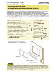
1.0 Introduction
The PE Series, hereafter referred to as the printer, is a high quality,
high volume, extremely durable print engine, designed exclusively for
use with label applicator systems.
Available in a wide range of configurations, the printer offers both
direct thermal or thermal transfer printing and comes equipped with
many popular bar codes, nine resident fonts, a smooth bit-mapped
font (CG Triumvirate ) and a scaleable font (CG Triumvirate Bold
Condensed ).
This manual provides all the information necessary to operate the
printer. To print labels or tags, simply refer to the instructions
included with the software you have chosen to create your labels.
Right-Hand Model
Figure 1-1
PE Series Operator’s Manual
Left-Hand Model
PE Series Print Engines
1
1.1
About This Printer
This printer offers the following standard and optional features:
1.1.1 Standard Features
Advanced Technology
This printer utilizes the Intel I960 32 Bit RISC Microprocessor
and Datamax application specific integrated circuitry (ASIC).
The ASIC design includes highly integrated components, along
with the Datamax proprietary SEAQ Circuit, which
maintains
printhead thermal control to provide consistent print quality.
Interfaces
This printer is equipped with two serial data communication
interfaces that support RS-232, RS-422, or RS-485 and one
Centronics® parallel data communication interface. The printer
is easily connected to any host using one of the cable
configurations listed in Appendix C.
Control Panel
The detachable/rotatable printer control panel has one liquid
crystal display (LCD), three LEDs, three primary operational
keys and six additional menu keys.
2
PE Series Operator’s Manual
1.1.2 Optional Features
300 DPI
This factory installed option provides a printhead resolution of
300 dots per inch with a 4.16 inch print width and 1MB DRAM.
Left-Hand
Left-hand label output model for system configuration
flexibility.
Memory Expansion
On-board memory DRAM expansion to 4 MB total for
expanded print length, temporary image storage and scaleable
font character cache.
FLASH Cartridge
A removable module used for permanent storage of custom
fonts, format and graphics. Available in 256K, 512K, 1 MB and
2 MB sizes.
Ribbon Saver
This factory installed option eliminates ribbon waste when
feeding past non-printed label areas.
PE Series Operator’s Manual
3
4
PE Series Operator’s Manual
Getting Started
2.0
Before Using This Printer
Unpacking the Printer
The printer was carefully packaged to avoid any damage during
transit. Before opening, closely inspect the box for damages. In the
event of shipping damage, contact the carrier immediately regarding
it’s nature and extent.
In order to operate the printer you will need to remove the
packaging materials that are placed inside the printer for shipment.
Complete the following steps before connecting power. It may be
helpful to refer to Figure 2-2 when removing the packing material.
n Remove the printer from the box.
o Remove the printer from the plastic bag.
p Remove the tape that extends over the printhead assembly.
q Remove the piece of foam between the printhead and platen.
r Remove the tape that covers the J-Hook on the Ribbon
Take-Up Hub.
; Note: Save all packaging materials in the event that shipping the
printer is ever required.
PE Series Operator’s Manual
5
Inspecting the Printer
After removing the printer from the box, check the remaining contents
of the package. In addition to this manual, the following items should be
present:
label printer installation guide
sample print labels
power cord
any special or additional items purchased
Additional Requirements
The following items are necessary for generating labels with your
printer. Contact your dealer or a technical support representative for
advice on media and software.
Serial or parallel interface cable (see Appendix C).
Applicable media (see Appendix F).
Applicable software
6
PE Series Operator’s Manual
2.1
General Overview
The following illustrations show the major components of your
printer. It may be helpful to refer back to this section for the names
and locations of the printer’s various parts.
Figure 2-1 Right-Hand Model, External Front View
PE Series Operator’s Manual
7
Figure 2-2 Right-hand Model, Interior Front View
Figure 2-3 Right-Hand Model, Media Path
8
PE Series Operator’s Manual
Setting Up the Printer
3.0
Introduction
This chapter explains how to connect the printer to the host, load
media and print a configuration label.
3.1
Connecting the Printer
; Note: Ensure that the printer’s power switch is ‘off’ when
connecting the AC power cord or any interface cable.
Connect the AC power cord to the back of the printer before plugging
into a properly grounded outlet. The printer can be connected to the
host computer with a parallel or serial cable, (see Appendix C). The
applicator connections should also be made at this time. The figure
below shows the position of the interface ports.
Figure 3-1 Connecting the Printer
PE Series Operator’s Manual
9
3.2
Loading Media
This section explains the loading of media.
n Move the Head-Lift Lever ‘up’ to raise the printhead, as
shown in Figure 3-2.
Figure 3-2 Head-Lift Lever
o Push ‘up’ on the hinged Drive Plate at the point shown in
Figure 3-3. This will release the plate, allowing it to swing
down.
Figure 3-3 Opening and Closing the Drive Plate
10
PE Series Operator’s Manual
p Peel the first 12 inches of label material from the liner and
discard.
; Note:
If you wish to leave the label attached to the liner do not
thread the media through the Drive Plate.
Figure 3-4 Media Loading
q Feed the liner as shown in Figure 3-4. Be sure that the liner
passes through the “fingers” of the Label Edge Sensor.
Continue feeding the liner, bringing it under the Drive Plate
Hinge Pin (see Figure 3-5). Pull through removing any slack.
; Note:
When using narrow media, it may be necessary to adjust the
position of the Label Edge Sensor to ensure detection. This
is done by turning the Edge Sensor Adjustment Knob (see
Figure 2-3).
PE Series Operator’s Manual
11
Figure 3-5 Media Loading (detail)
12
r
To close, raise the Drive Plate back up, until the plate snaps
into place. See Figure 3.3.
s
Lower the Head-Lift Lever until the printhead is locked in
the down position.
PE Series Operator’s Manual
3.3
Loading Ribbon (Thermal Transfer)
The printer can use two methods to create an image on the media.
The first method, called direct thermal, uses specially treated label
stock containing dyes that turn black with heat and pressure.
The second method is thermal transfer, which involves the transfer of
ink from a ribbon substrate onto the media with heat and pressure.
The ink is transferred to the label stock as it passes between the
printhead and the platen roller. To use this method, set the printer to
“transfer” before printing.
; Note: Ribbon should never be used with direct thermal stock.
Using this stock with a ribbon will result in poor quality print.
Complete the following steps to load ribbon:
n Unlatch and raise the printhead.
o Slide the ribbon roll onto the Ribbon Supply Hub with the
leader coming over the top of the roll. Ensure that the ribbon
roll is pushed back fully against the flange at the base of the
Ribbon Supply Hub.
p Thread the ribbon along the path as shown in Figure 3-6.
Figure 3-6 Ribbon Loading Path
PE Series Operator’s Manual
13
q Remove the J-Hook from the Ribbon Take-up Hub, ( as a
convenient option you may use an empty ribbon core to
rewind the spent ribbon, if using this method do not reinstall
the J-Hook).
r While holding the Ribbon Take-up Hub, rotate the J-Hook to
unlatch it.
s Raise the J-Hook away from the hub and place the end of the
ribbon over the take-up hub.
Figure 3-7 J-Hook
t Slide the J-Hook back into place as shown in Figure 3-7.
While holding the Ribbon Take-up Hub, rotate the J-Hook
until it latches. Turn the Ribbon Take-up Hub several times
to secure the ribbon.
u Lower the Head Lift Lever until the printhead is locked in the
down position.
14
PE Series Operator’s Manual
3.4
Ribbon Removal
Removal of a Partially Used Roll of Ribbon
Complete the following steps to remove and save a ribbon:
n Cut the ribbon at the point shown in Figure 3-8.
o Turn the Ribbon Take-up Hub until the end of the ribbon
has cleared the printhead area.
p Grasp the roll of used ribbon and slide the used ribbon
straight off the Ribbon Take-up Hub. Discard the used
ribbon.
q Grasp the roll of unused ribbon, pull and slide the unused
ribbon from the Ribbon Supply Hub, storing it for future use.
Figure 3-8 Ribbon Cutting Point
PE Series Operator’s Manual
15
Removal of a Completely Used Ribbon
Complete the following steps to remove a completely used ribbon:
n Unlatch and raise the printhead.
o Rotate the Ribbon Take-up Hub, winding it until the ribbon
clears the media path.
p Rotate the J-Hook, unlatch and remove.
q Grasp the roll of used ribbon and pull it straight off of the
Ribbon Take-up Hub and discard.
Supply
Take-Up
16
r Pull the empty ribbon supply core from the Ribbon
Hub. Save the core for later use on the Ribbon
Hub or discard.
PE Series Operator’s Manual
3.5
Installing a FLASH Cartridge
FLASH cartridges provide the same features as DRAM, with the
added benefit of providing permanent storage for custom fonts, label
formats and images. FLASH memory is essentially a non-volatile,
electronically erasable PROM. A write protect switch on the
cartridge is used to safeguard stored data against accidental erasure.
To install a memory cartridge:
n Turn ‘off’ and unplug the printer.
o Remove the two screws securing the Electronics Access
Panel and open to reveal the connector, see figure below.
Figure 3-9 FLASH Cartridge Connector Location
PE Series Operator’s Manual
17
p Holding the FLASH Cartridge with the label facing up,
insert it into the connector, see Figure 3-10. Push firmly,
but do not force it, doing so could damage the cartridge and
socket.
Figure 3-10 Inserting the Memory Cartridge
q Close the Panel and secure it with the screws. Plug in and
turn ‘on’ the printer. The printer will refer to the FLASH
Cartridge as Module B.
18
PE Series Operator’s Manual
3.6
Printing a Configuration Label
Before beginning, load the printer with 4” wide media or configure
the Label Width Adjustment in the Advanced Setup Menu to meet
your label width, (for thermal transfer, also use a matching ribbon.
For direct thermal labels, be sure that “Direct” has been selected in
the "Print Method"). See Section 4 for more setup information. To
print a Configuration Label:
n Turn the printer ‘Off”.
o Press and hold the ‘Feed’ button while turning the printer
‘On’.
p Release the ‘Feed’ button after the printer display reads
‘DYNAMIC RAM DIAGNOSTICS’...
After a brief period, the labels will be printed. (If the labels are not
printed, see Section 7). Referring to Figure 3-11, the Configuration
Label contains two types of information. The first type is printer
setup data. The second is a pattern, testing the print circuitry. In
addition, a special connector can be used to test communications,
see Section 4 on Serial Loopback for more details.
; Note: After running the Configuration Label, the printer will enter
Character Dump Mode and must be reset in order to run a
label application. To reset, power the printer ‘Off’ and then
‘On’. For Character Dump Mode information see Section 7.
PE Series Operator’s Manual
19
COM M UNICATION OPTIONS
INPUT PORT _ _ _ _ _
PORT A
BAUDRATE _ _ _ _
9600
PARITY _ _ _ _ _ _ _
NONE
WORD LENGTH _ _ _
8 BIT
STOP BITS _ _ _ _ _ _ _ 1
PROTOCOL
BOTH
CONTROL CODES
STANDARD
OPERATION
PAUSE M ODE _ _ _ _ _
FEEEDBACK M ODE _ _
TEST M ODE _ _ _ _ _
DISABLE
DISABLE
DISABLE
LABEL OPTIONS
HEAT SETTING _ _ _ _ _ _ _ _ 10
PRINT SPEED _ _ _ _ _ _ _ _ _ 6.0 IPS
SLEW SPEED _ _ _ _ _ _ _ _ _ _ 8.0 IPS
BACKFEED SPEED _ _ _ _ _ _ _ 5.0 IPS
ROW ADJUST _ _ _ _ _ _ _ _ _ _
0 in
COLUM N ADJUST _ _ _ _ _ _ _
0 in
LABEL WIDTH _ _ _ _ _ _ _ _ _ 410 in
CONT. LABEL LEN _ _ _ _ _ _ _
0 in
PRESENT DIST _ _ _ _ _ _ _ _ 320 in
PE INFORM ATION
LOW RIBBON INCHES _ _ _ _
PRINTER M ODEL _ _ _ _ _ _ _
20
RIGHT
TUE FEBRUARY 17 , 1998 14:07 048
DATABASE INFORM ATION
SECURITY _ _ _ _ _ _ _ _ _ _ NONE
VER: HA - 02 . 30 02/07/98
ROM CHECKSUM S
U39 47-2081-03K
U37 47-2080-03K
U38 47-2166-01B
U40 47-2067-01B
SYSTEM RAM CHECKS _ _ _ _ _
GOOD
SYSTEM RAM SIZE _ _ _ _ _ _ _ _ 512 KBYTES
SERIAL LOOPBACK CHECK_ _ _ _ _
GOOD*
CTS & DTR LOOPBACK CHECK_ _ _ _ _
GOOD*
BASIC FUNCTIONS
PRINT M ETHOD _ _ _ _ _ _ _
SELECT TOF _ _ _ _ _ _ _ _
DARKNESS _ _ _ _ _ _ _ _ _ _
CUTTER _ _ _ _ _ _ _ _ _ _ _ _
RIBBON SAVER _ _ _ _ _ _ _
INTERNAL BATCH _ _ _ _ _
CONVERSION _ _ _ _ _ _ _ _
TOP ADJUST _ _ _ _ _ _ _ _ _
TRANSFER
GAP
33
DISABLE
DISABLE
DISABLE
DECIM AL
64
COM PATABILITY
DPI EM ULATION
OFFSET BIAS
203
220
HARDWARE
BATTERY LEVEL _ _ _ _ _ _ _ GOOD
THERM ISTOR ADC _ _ _ _ _ _ 65
REFLECTIVE ADC _ _ _ _ _ _ _ 0
TRANSM ISSIVE ADC _ _ _ _ _ 165
PAPEROUT ADC _ _ _ _ _ _ _ _ 0
INSTALLED OPTIONS
RIBBON SAVER _ _ _ _ _ _ _ _ NO
CUTTER
_ _ _ _ _ _ _ _ _ _ _ _ NO
PE SIGNALLING
PE APPLY HW _ _ _ _ _ _ _ _ _
PE EXT SIGNAL _ _ _ _ _ _ _ _
RIBBON LOW ACTIVE _ _ _ _
BACKFEED CONTROL _ _ _ _
DISABLE
LOW PULSE
LOW
20ms
COUNTER INFORM ATION
ABSOLUTE VALUES 02-10-98
LENGTH _ _ _ _ _ _ _ 11644 INCHES
M EM ORY CONFIGURATION
INTERNAL M ODULE _ _ _ _ _ _ _ _ 32
SCALABLE FONTS _ _ _ _ _ _ _ _ _
0
SYM BOL SET _ _ _ _ _ _ PC-850 M ODIFIED
* ONLY PRESENT WITH SPECIAL TEST PLUG
Figure 3-11 Configuration Label
; Note: Your Configuration Label may vary due to the printer
configuration or the printer firmware version.
20
PE Series Operator’s Manual
PE Series Operator’s Manual
21
3.7
Configuration Label Explanation
February 17, 1998 14:13 048 - Printer date and time, including Julian
calendar date.
Database Information--Includes serial number, security setting,
firmware version, ROM Checksums, and the amount of DRAM. Serial
Loopback Check and CTS/DTR Loopback Check results (if equipped
with the proper test plug, see Section 4, Figure 4-1).
Counter Information--Includes the absolute counter values (the total
amount of media through the printer, in inches) and the total number of
hours in operation.
Memory Configuration--Lists the amount of Printer memory allocated
for Internal Modules or Scaleable Fonts in 4 KB blocks.
Label Options--Lists label related settings.
PE Information--Specifies Printer model and the Low Ribbon Warning
setting.
Hardware--Lists the current readings of some Printer sensors.
Installed Options--Lists the Printer’s options.
PE Signaling--Lists the settings for applicator interfacing and backfeed
control.
Communication Options--Lists all communication settings including the
active port.
Operation--Indicates the operations that are available, and whether or not
they have been enabled.
Basic Functions--Lists the settings for the Basic Function Menu.
Compatibility--(PE 42 only) Changes the dots per inch.
22
PE Series Operator’s Manual
3.8
Test Pattern Label
The second of the labels is the Test Pattern Label, see Figure 3-12.
This matrix is useful to determine the Printhead condition. For more
information concerning maintenance, see Section 6.
Good test label indicates
Printhead is operating
normally.
Streaks in test label indicate a
dirty or faulty Printhead.
(See Chapter 6 for cleaning
instructions).
Figure 3-12 Test Pattern Label
PE Series Operator’s Manual
23
3.9
Applicator Connection
The applicator mechanism will receive the printed label and affix it
to an item. Applicator configuration and it’s communication with
the printer must be coordinated. The applicator interfaces into the
printer’s DB-9P Applicator Port. The table below lists the functions.
(Direction is given relative to the Printer.)
; Note: All output signals are open collector.
Pin #
1
2
3
4
5
6
7
8
9
Function
+5 Volt Output
Ribbon Low signal
Machine Error
(Not used)
Start Print signal
End Print signal
Label Out signal
Ribbon Out signal
Signal Ground
Direction
Out
Out
Out
N/A
In
Out
Out
Out
N/A
Table 3-1 Applicator Port Pin Assignments
Pin function explanation:
Pin 1 - The Printer provides a +5 VDC, Output, fused at 1A.
Pin 2 - The Ribbon Low signal goes low when the diameter of the ribbon
supply is at the LOW RIBBON INCH setting in the setup menu.
See Section 4 for more information.
Pin 3 - The signal goes low when the Printer detects a Cover Open, Head
Open, or Buffer Full error condition. It stays low until the error
condition is corrected.
Pin 4 - Not Used
24
PE Series Operator’s Manual
Pin 5 - The Start Print signal is sent from the Applicator to the Printer
when the Applicator is ready to begin another cycle. Also, data
from the host must be sent to the Printer before the Start Print
signal is sent from the Applicator. See Appendix D for a test
box schematic.
Pin 6 - The End Print signal is sent from the Printer to the Applicator
when a printed label is ready for the Applicator. The signal is
used to synchronize a device with the print cycle. The End Print
signal can be set for one of five types through the menu, see
Figure 3-13. The options are:
A Low Pulse (0V for 30 msec.) at the end of print.
A High Pulse (5V for 30 msec.) at the end of print.
A steady Low signal (0V) throughout the print cycle.
A steady High signal (5V) throughout the print cycle.
Disabled.
Figure 3-13 "End Print" Signal Options
Pin 7 - The Label Out signal goes low when the Printer is out of stock.
Pin 8 - The Ribbon Out signal goes low when the Printer is out of
ribbon. (When this signal goes low, the Ribbon Low signal on
Pin 2 resets to high.)
Pin 9 - Signal Ground.
PE Series Operator’s Manual
25
3.10 Options Port
The Options Port is used for external control of the printer via
discrete lines. The Port consists of +5V, Ground, three outputs, and
four inputs. This port can be manipulated via DPL (Datamax
Programming Language). For more information consult the
Programmer’s Manual.
PIN #
1
2
3
4
5
6
7
8
9
Description
+5 VDC, Fused 5A
Output 1, 7406 Open Collector
Output 2, 7406 Open Collector
Output 3, 7406 Open Collector
Input 1, Inverting Schmitt Trigger
Input 2, Inverting Schmitt Trigger
Input 3, Inverting Schmitt Trigger
Input 4, Inverting Schmitt Trigger
Ground
Table 3-2 Options Port Pin Assignments
26
PE Series Operator’s Manual
PE Series Operator’s Manual
27
Using Your Printer
4.0
Using the Printer’s Front Panel
The printer’s detachable/rotatable front panel contains nine buttons,
three lights and a 2x16 character display with contrast adjustment.
The functions and features are as follows:
Figure 4-1 Front Panel
Control Buttons
Pause This button temporarily stops the current
print
job. Printing will resume when pressed a
second time.
Feed Pressing this button will feed one label. When pressed
during a print job, the label will feed upon completion of the
job. Also, pressing Feed will clear an alarm condition.
Cancel Pressing this button one time will clear the current
job, pause the printer, and prepare the next job (if any).
When more than one job has been sent to the printer, only the
current job is canceled, all other jobs are unaffected.
However, repeatedly pressing this button will remove the
remaining jobs from the cue, one by one.
28
PE Series Operator’s Manual
Lights
Power This illuminates when the printer is powered ‘on’. A
delay of up to one second is normal at ‘power up’ or ‘power
down’.
Ribbon/Paper This illuminates to indicate a fault in the
media or ribbon path. Rapid flashing indicates a low-ribbon
condition.
Pause This illuminates when the printer is paused and is
‘off’ when the printer is at Ready.
Menu Keypad
Õ × Ö Ø The four arrow keys are used to move through
the printer’s menu tree, scroll through options and increment
or decrement certain definable values. In general, × and Ø
move to the next higher or lower menu level, while Õ and
Ö scroll through the choices within the same level. See
Appendix G.
Enter Selects the option currently displayed.
Shift Used to change fields on certain menu items. (e.g.
Comm Setup/Serial parameters)
LCD Contrast
Allows the user to change the intensity of the display. Use a
small screwdriver to adjust the display contrast. Turning the
potentiometer counter-clockwise increase the contrast.
PE Series Operator’s Manual
29
4.1
Accessing the Menu Tree
The menu is divided between basic function and advanced setup
levels. (To see a complete overview, the Menu Tree is located in
Appendix G.)
; Note: Default values or settings may vary depending on the version
and customer applications. Factory default settings will be
indicated with * symbol.
4.1.1 Basic Functions
There are nine basic functions including a gateway to the advanced setup
level.
Print Method
Sensor Top of Form
Darkness
Start of Print
Column Adjust
PE Applicator HW
Advanced Setup
LCD :
UVF!!GFC14!!22;66B
!!!
SFBEZ
From the Printer Ready screen, enter the Basic Function screen by
pressing the Ø key :
Qsjou!Nfuipe
Controls the type of print method to be used.
Direct
*Transfer
Enables direct-thermal printing (no ribbon).
Enables thermal-transfer printing (ribbon installed).
Tfmfdu!UPG
Controls the type of media sensing to be used.
*Gap
Reflective
Continuous
Senses on a gap or notch between each label.
Senses on a reflective mark between each label.
Senses only presence, TOF set by label format.
30
PE Series Operator’s Manual
Ebsloftt
*Factory preset
Value range: 1-64
Fine tunes the print contrast level. Used to match
print contrast level when replacing the printhead.
Selectable with 64 indicating maximum darkness.
Tubsu!pg!Qsjou
*Factory preset Value
range: 0-128
Fine tunes the horizontal print position on the
label. Allows a matching start of print position
between multiple printers sharing the same label
formats.
Zero is forward, while 128 is the furthest back.
Dpmvno!Bekvtu
Fine tunes the print position to the left or right on
the label. Zero is all the way to the left.
* Factory preset value
range: 0-128
QF!Bqqmjdbups!I
X
Enable
*Disable
Bewbodfe!Tfuvq
PE Series Operator’s Manual
Switches control of print cycle operation,
applicator port pin #5 on or off.
Enables an applicator to control the print cycle.
Ignores any applicator signal.
Press the Ø to access to the printer’s advanced
options.
31
4.1.2 Advanced Setup
Advanced setup is a gateway leading to additional system, maintenance
and testing sub-levels.
PE Options
Low Ribbon Diameter
Printer Model
Counters
Date/Time
Label Options
System Options
Compatibility
Operation
Communications
Maintenance
Modules
LCD :
CBTJD!!!GVODUJPO
BEWBODFE!!TFUVQ
From Basic Function/Advanced Setup, enter by pressing the Ø key:
QF!Pqujpot
Three selections used to integrate functions with an
applicator.
PE Output Signal
Selects the type of status signal used between the
printer and applicator port pin #6.
High to low signals end of print cycle.
Low to high signals end of print cycle.
Steady low signal during printing.
Steady high signal during printing.
No print and apply function.
*Low Pulse
High Pulse
Low Status
High Status
Disable
32
PE Series Operator’s Manual
QF!Pqujpot
(cont.)
Backfeed Cntrl
*20 ms after print
40 ms after print
60 ms after print
80 ms after print
99 ms after print
no backfeed
before print
Ribbon Low
*Active Low
Active High
Sjccpo!Mpx!Ejb
/
*20
Value range: 14-34
Controls the timing associated with the backfeeding
of a presented label.
20 millisecond delay before printing the next label.
40 millisecond delay before printing the next label.
60 millisecond delay before printing the next label.
80 millisecond delay before printing the next label.
99 millisecond delay before printing the next label.
Disables all backfeed motion.
Backfeeds without delay, upon next print cycle.
Sets the output polarity of the applicator port pin #2
ribbon low signal.
Signal goes low for ribbon low condition.
Signal goes high for ribbon low condition.
Allows user to select how much ribbon will remain
when a Low Ribbon message is displayed.
The value selected is the remaining diameter in
tenths of an inch.
*Left Hand
*Right Hand
Instructs the printer of the mechanism’s configuration
for printhead zero dot orientation.
Right side label output.
Left side label output.
Dpvoufst
Read only check of the printer’s absolute values.
Absolute Values
Given in inches; not resettable.
Ebuf0Ujnf
Allows the current date and time fields to be
changed.
Mbcfm!Pqujpot
Allows access to six label parameters.
Heat Setting
Allows the selection of different heat settings.
Changes the "on time" of the printhead dots.
Qsjoufs!Npefm
*10
Value range: 0-30
The higher value, the darker the print.
PE Series Operator’s Manual
33
Mbcfm!Pqujpot
(cont.)
Print Speed
*6.0 ips
Value range:
model dependent
Slew Speed
*8.0 ips
Value range:
model dependent
Backfeed Speed
*5.0 ips
Value range:
2.0 -5.0 ips
Label Width
*410 or
416, respectively
Value range:
Present Position
*245
Values range:
0 -999
34
Allows the selection of different rates that the label
will be printed.
PE 42; 2 to 10 ips (51 - 254 mm/sec)
PE 43; 2 to 8 ips (51 - 203 mm/ sec)
Allows the selection of different rates that the printer
will feed during non-printed portions of each label.
PE 42; 2 to 10 ips (51 to 254 mm/sec)
PE 43; 2 to 8 ips (51 - 203 mm/sec)
Allows the selection of different rates that the printer
will backup labels.
Range is the same for both models.
Changes useable label width, as when printing on
media narrower than 4.1 inches; reducing width
increases memory for label formatting. Also allows
printing of Configuration Labels on narrow media.
The printer must be reset for the new value to be
recognized.
PE 42; 100 to 410 (1.00 to 4.10 in.)
PE 43: 100 to 416 (1.00 to 4.16 in.)
Sets the label’s stop point (Set Form Stop) after
printing. This value is independent of the Offset Bias
value (Start of Print Position), yet must be greater to
have any effect.
At default this function will have no effect on last
label positioning.
0.00 to 9.99 inches.
PE Series Operator’s Manual
Tztufn!pqujpot
Allows access to eight system level options.
Factory Settings
Returns all printer settings to factory defaults, with
the exception of Serial Number, Top-of-Form
Adjust, Printer Model and Darkness.
Press ‘Enter’ to reset or × to abort.
Are you sure?
Security Check
*None
Password
Allows user to password protect the advanced setup.
Allows free access to all menu functions.
Must enter correct password for access.
Modify Password
*0123
Allows the user to enter an alphanumeric password.
Use the Õ or Ö keys to scroll for a new value.
Press ‘Shift’ to move to the next position. Press
‘Enter’ to accept the new setting.
Internal Module
Allocates a portion of memory to be used for storing
image and label format data.
128 KB reserved as Module A.
Memory is allocated in 4 KB blocks; the reserved
space is designated as Module A.
*0032
Value range:
0 - 1000
Scaleable Font
*0000
Value range:
0 - 1000
Symbol Set
Allocates a portion of memory to be used for loading
of scaleable font data.
No reserved font cache.
Memory is allocated in 4 KB blocks. The minimum
requirement is 0015 (60 KB); the recommended
value is 0025 (100 KB) for Smooth Scaleable Fonts.
Allows user selection from 29 different scaleable
font symbol sets.
*PC-850 modified
PE Series Operator’s Manual
35
Dpnqbubcjmjuz
Three selections to control label positioning
Offset Bias
*220
110
Selects from two different Start of Print positions.
This command sets the point where printing starts,
relative to the Top-of-Form Adjust value. The
printer will feed from the Offset Bias and the Topof-Form Adjust value to begin printing.
Positioning
(PE 42 only)
*203 dpi
200 dpi
Allows the selection of the column position
calculation based upon one of two different values.
Exact column positioning.
Host CMDS-Ignore
This parameter instructs the firmware whether to
process the DPL commands for Offset Position
(<stx>O), Peel Possition (<stx>f), and the Heat value
(stx>l>h)
ProdigyPlus Mode
This function sets the parameters so the printer will
emulate a Prodigy Plus printer. These parameters
are:
Offset Bias = 110
Positioning = 200DPI
Host Positioning = IGNORE
Conversion = Inches
Peel Position = .25" (1" if cutter is installed)
Pqfsbujpo
Sets three different operational functions.
Pause Mode
Causes the printer to pause between printing each
label.
*Disable
Enabled
Feedback Mode
*Disable
Enable
36
The ‘Pause’ button must be pushed in order to print
the next label.
Causes the printer to feedback ASCII characters 30
and 31.
The printer will return a 30 after each label is
printed and a 31 after each batch of labels.
PE Series Operator’s Manual
Pqfsbujpo
(CONT.)
Test Mode
Causes the printer to send debug characters back to
the host. See Appendix E for listings.
*Disable
Enable
Cutter
Enable
*Disable
Controls an external cutter mechanism.
Enables an external cutter.
Cutter not being used.
Ribbon Saver
Enable
*Disable
Controls the optional Ribbon Saver feature.
Enables the option.
Option is not installed or disabled.
Conversion
Sets standard or metric measurement, automatically
updating all operations with the new selection.
Measurements in inches
Measurements in millimeters
*Decimal
Metric
Dpnnvojdbujpot
Comm Setup
*PORTA
*9600
*8 *N *1 *BOTH
Allows the user to select communication values for
each port.
Selects the port and sets parameters.
Selects serial Port A, B or Parallel communication.
Selectable serial baud rates: 300, 600, 1200, 2400,
4800, 9600, 19200.
Sets word length: 7 or 8 bits.
Sets parity bit: E = even, O = odd, N = none.
Sets stop bit length: 1 or 2 bits.
Selects handshaking method: XON/XOFF,
CTS/DTR or BOTH.
Control Codes
Sets the DPL control code values.
*Standard Codes
Alternate Codes
01 Hex = SOH command, 02 Hex = STX command
5E Hex = SOH command, 7E Hex = STX command
PE Series Operator’s Manual
37
Nbjoufobodf
Selects five different maintenance functions.
Test Print
Each test print function is activated by pressing the Ø
key.
Prints labels reflecting the printer’s current settings.
Prints labels reflecting the menu settings.
Prints a series of Ribbon Test Labels.
Printhead dot pattern test label.
Current Config
Database Config
Test Ribbon
Test Pattern
Front Panel
LED Test
Keypad Test
Display Test
Test I/O
Monitor GP Input
Test GP Output
Sensor Readings:
Digital
Analog
Serial Loopback
Serial Port A
Serial Port B
38
Tests three different Front Panel functions.
Toggles the Ribbon/Paper and Pause LED’s on the
control panel.
Allows user testing of the six-button menu control
pad. The display will indicate the functions of the
keys as they are pressed. Pressing twice on the ×
will exit the test.
Cycles alphanumeric characters through each
segment of the LCD display.
Tests three different I/O functions.
Active monitor of the General Purpose I/O inputs.
Tests the General Purpose I/O outputs.
Divided into two sections.
Indicates the conditions of the printer’s digital
sensors. The top line contains the sensor input,
while the bottom line shows the sensor state. See
Table 4-1 for definitions.
Indicates the converted values of four analog
sensors. The top line contains the sensor input, while
the bottom line shows a digital representation of the
analog value. See Table 4-1 for definitions.
Serial Loopback tests the internal transmit, receive
and CTS/DTR signals. A special loopback plug
must be installed on the port under test (see Figure 41). When complete, the printer will respond with the
results.
Tests Port A.
Tests Port B.
PE Series Operator’s Manual
Nbjoufobodf
(cont.)
Installed Options
Cutter
Ribbon Saver
There are two installed options to choose from:
Npevmft
Module A
Module B
Modules contain a set of five memory function
routines. Some of these memory tests are
destructive, in this case, the printer will prompt “Are
you sure?” before beginning.
Prints a list of all files (fonts, images and labels),
stored on the selected module.
Module A is the printer's internal memory allocation.
Module B refers to an external Flash, if equipped.
Print File
Print File on
Module A
Print File on
Module B
Prints a file from a selected module.
Prints from Module A; specify file type and then file
name. The printer will then print the contents.
Same function as Module A, but prints the specified
contents of the external module file.
Copy Module
Copy From
Module A
Copy From
Module B
Copies data from one module to another.
Copies from Module A to Module B.
Format Module
Formats a selected memory module.
Caution! Formatting permanently erases data!
Print Directory
Format Module A
Format Module B
Test Module
Test Module A
Test Module B
Copies from Module B to Module A.
Formats Module A. Printer will prompt, “Are You
Sure?” All data will be lost.
Same as Module A. The Write Protect Switch must
be turned ‘Off’ to format this module.
Tests the selected memory module by writing to,
reading from and then verifying the data for accuracy.
Caution! Testing permanently erases data!
Tests Module A. The printer will prompt, “Are You
Sure?” All data will be lost.
Same as Module A. The Write Protect Switch must
be turned ‘Off’ to test this module.
PE Series Operator’s Manual
39
Inputs
Sensor Name
Possible Condition
HD
Head
D = Down, U = Up
CT
Cutter
D = Down, U = Up
SP
Present Sensors
Y = Blocked, N = Not
Blocked
RS
Ribbon Saver
D = Down, U = Up
RM
Ribbon Motion
1 = Blocked, 0 = Not
Blocked
THR
Thermistor
0-255
REF
Reflective
0-255
TRAN
Transmissive
0-255
PO
Paper Out
0-255
Table 4-1
Figure 4-2
40
Sensor Definitions
Serial Loopback Test Plug Connections
PE Series Operator’s Manual
PE Series Operator’s Manual
41
PRINTER ADJUSTMENTS
5.0
Introduction
When changing label size or material it may be necessary to adjust
certain printer components and label settings. This chapter provides
step-by-step instructions for completing these adjustments. If there
is any doubt about your ability to perform these procedures, contact
a qualified service technician, a technical support representative or
software representative.
5.1
Media Sensor Adjustment
To detect the label’s edge, notch or black stripe, the printer uses a
label edge sensor that is adjustable across half the media path. The
position of this sensor may need to be adjusted when changing types
of labels or when going from wide to narrow labels.
Referring back to Figure 2-3, locate the Edge Sensor Adjustment
Knob on the printer. This will adjust the sensor position across the
label. If you are experiencing a problem with the label top of form,
try adjusting this sensor. If using labels that are die-cut or that have
a black stripe across the back, position the sensor near the middle of
the label. If using labels that have a notch, irregular edge or with a
black stripe that does not cover the entire width of the label, turn the
adjustment knob in half turn increments until the label is sensed. See
Section 7 for more information.
42
PE Series Operator’s Manual
5.2
Media Width Adjustment
The printer is able to use a wide variety of media types, widths and
thickness. The printhead mechanism has a feature that allows the
user to make a leveling adjustment. This adjustment is required
when using labels that are less than 4” wide.
Figure 5-1 Adjusting Media Width
Load the Printer with the chosen media. Begin printing your label
format. Rotate the Head Level Adjustment Knob, (see Figure 5-1)
clockwise until the print quality along edge starts to lighten. Finally,
rotate the knob back just enough to achieve uniform print quality
across the label, see below.
Print beginning to lighten.
Proper final adjustment.
Figure 5-2 Example of the Media Width Adjustment
PE Series Operator’s Manual
43
; Note: Labeling program settings can override many of the functions
available through the printer’s menu.
5.3
Label Start of Print
Start of print position can be affected by the position of the label
edge sensor, especially if the labels are irregularly shaped. Once
properly positioned, the start of print position can be adjusted by
using the <STX>O command or through your labeling program.
Also, the TOF Adjust provides additional printer specific adjustment
and can be found in the Basic Function Menu.
5.4
Label Presentation
Following the printing of a label, the printer will position the label
according to it’s programmed Present Distance. The value will be
dependent upon the needs of the applicator system. The Present
Distance value can be input using the <STX> f system level
command, through Label Options in the Advanced Setup Menu or
through your labeling program.
44
PE Series Operator’s Manual
5.5
Setting Start of Print and Peel Position
Every effort has been made to make the default parameters work for your
application right out of the box. Due to the vast number of software
packages, applicators, and label formats this is not always the case. The
following steps may help your setup of the printer.
Step
1
2
Description
Disable the Host Positioning parameters.
Set COMPATABILITY/HOST POSITIONING to IGNORE. This
ensures that after setup the host label software cannot override the
printer.
Concentrate on getting any printed fields aligned on your label
media.
a. (Only required on Right Handed printer models). Select the
LABEL OPTIONS/LABEL WIDTH to the proper value. A
value larger is better than smaller.
b. (Up/Down Adjustment). Modify the BASIC
FUNCTION/START of PRINT parameter until print is
horizontally aligned.
c. (Left/Right Adjustment). Modify the BASIC
FUNCTION/COLUMN ADJUST until print is vertically
aligned.
The label should be printing in the correct locations.
3
Adjusting the correct Peel Position using the LABEL
OPTIONS/PEEL POSITION parameter.
This parameter is measured relative the COMPATABLITY/
OFFSET BIAS selection. If the Offset Bias is set to 220 (default)
then setting the Peel Position to 245 will extend the peel position
an additional .25 inches. A value of 320 would be an additional 1
inch.
PE Series Operator’s Manual
45
5.6
Controlling Print Quality
The printer provides maximum flexibility by offering both direct
thermal and thermal transfer printing capabilities. To support these
printing options, the printer has a flexible set of printing controls.
The amount of heat applied by the printhead and the location of the
printhead in relation to the label media have the most effect on the
images that are printed on the labels. The printer provides
adjustments for quality, but limits them to prevent possible damage
to the printer. For example, low cost direct thermal stocks have very
high reaction temperatures, therefore it takes a great deal of energy to
make clear images on this type of media. This is also true for some
thermal transfer materials, (see Appendix F; Media and Ribbon
Overview). The printer provides three ways to compensate for this:
Increase the darkness setting in the Basic Functions Menu
(this will give only slight adjustment).
Use the H label formatting command to increase the software
heat setting for a specific format, use the Heat Setting option in
the Advanced Setup Menu for all formats or make adjustments
through your labeling program.
Use the P label formatting command to adjust the print speed for
a specific format, use the Print Speed option in the Advanced
Setup Menu for all formats or make adjustments through your
labeling program.
46
PE Series Operator’s Manual
PE Series Operator’s Manual
47
MAINTENANCE
6.0
Introduction
The chapter covers the cleaning recommendations for your printer.
The following items will help clean your printer safely and
effectively.
Isopropyl alcohol
Cotton swabs
Clean, soft and lint-free cloth
Soft-bristle brush or compressed air
Mild detergent
CAUTION
For your safety and to avoid damaging the Printer,
always power off and unplug the unit before cleaning.
Interior and Exterior Cleaning
48
Interior
During normal operation, dust particles from the
label stock accumulate inside the printer. These
particles can begin to foul the print. To prevent
build-up, use a soft-bristle brush or compressed
air as needed for removal.
Exterior
The exterior can be cleaned using a general
purpose cleaner and a damp soft-cloth or
sponge. Do not use abrasive cleansers or
solvents.
PE Series Operator’s Manual
6.1
Cleaning Schedule
The following table provides a recommended cleaning schedule for
various parts of your printer.
CAUTION
Area
Printhead
For your safety and to avoid damaging the Printer,
always power off and unplug the unit before cleaning.
Method
Using isopropyl alcohol and a cotton
swab, clean the printhead from end to
end. Removing all adhesive and dirt.
Platen Roller
Rotate the platen, cleaning it thoroughly
using isopropyl alcohol on a cotton swab
or lint-free cloth.
Media Path
Compressed air / soft-bristle brush and
isopropyl alcohol.
Peel/Tear Bar
Isopropyl alcohol
Media Sensor
Compressed air, isopropyl alcohol if
needed.
Soft-brush or compressed air.
Mild detergent.
Interior
Exterior
Interval
Clean after each
roll of ribbon or
each roll of directthermal labels.
Clean after each
roll of ribbon or
each roll of directthermal labels.
As needed, based
on weekly visual
inspection.
As needed, based
on weekly visual
inspection.
Monthly or as
needed.
As needed.
As needed.
Table 6-1 Printer Cleaning Schedule
PE Series Operator’s Manual
49
6.2
Cleaning the Printhead
When print quality begins to degrade the typical cause is a dirty
printhead. Unreadable barcodes, print drop-out areas, streaking and
smudging are all possible symptoms. In addition, if this build-up is
left on the printhead it will greatly reduce it’s life. Follow this simple
procedure to clean the printhead:
n Turn ‘Off’ and unplug the printer.
o Open the cover. Raise the Head-Lift Lever ‘up’ to access
the printhead. Move ribbon or paper away as necessary.
p Gently wipe the underside of the printhead clean using a
cotton swab moistened (not soaked) with isopropyl alcohol.
Allow to dry.
q Re-install ribbon and media, if necessary. Lower the
printhead by turning the Head-Lift Lever ‘down’ until it locks
into position.
r Close the cover. Plug in and turn ‘On’ the printer. Feed
several labels to normalize label tracking.
Figure 6-1
Cleaning the Printhead
; Note: NEVER use a sharp object when cleaning the printhead.
50
PE Series Operator’s Manual
6.3
Cleaning the Platen Roller
Print quality may be affected if the platen becomes contaminated
with grit, label adhesive, or ink. To clean the platen:
n Turn ‘Off’ and unplug the printer.
o Open the cover. Raise the Head-Lift Lever ‘up’ to access
the printhead. Move ribbon or paper away as necessary.
p Using a clean lint-free cloth dampened with isopropyl
alcohol wipe off any debris from the platen. Manually
rotate the roller, cleaning the entire surface. Allow to dry.
q Re-install ribbon and media, if necessary.
r Lower the printhead by turning the Head-Lift Lever ‘down’
until it locks into position.
s Close the cover. Plug in and turn ‘On’ the printer. Feed
several labels to normalize tracking.
; Note: If the platen has excessive build-up that cannot be removed
with isopropyl alcohol, you may use acetone sparingly.
NEVER use a sharp object when cleaning the platen roller.
PE Series Operator’s Manual
51
TROUBLESHOOTING
7.0
Introduction
Occasionally, situations occur that require some troubleshooting
skills. Possible problem situations and potential solutions are listed
in this section. While not every situation is addressed, you may find
some of these tips helpful. If you do not feel comfortable performing
the action or for problems that may persist or that have not been
covered in this section, contact a Technical Support Representative.
7.1
Troubleshooting Tips
The Printer fails to power up (no lights):
Verify that the AC power connection has been made at both the
wall and the printer and the power switch is turned ‘on’.
Verify that the AC power outlet being used is operating
correctly. Test the outlet by connecting another device to it.
The AC power cord may be damaged; replace.
The Printer’s power switch may be defective or the fuse may be
blown; call for service.
52
PE Series Operator’s Manual
No display (the Power LED is on):
The display contrast may be set too low. Using a small
screwdriver use the access opening on the front panel and
increase the setting.
The printer may have a bad connection to the display or the
display may be faulty; call for service.
Black boxes in display:
The printer has failed to initialize. Power the printer ‘Off’.
Hold down the Pause, Feed and Stop/Cancel buttons while
powering the printer ‘On’.
Defective display/main PCB; call for service.
Skips Labels (every other):
The label is formatted too close to the top edge of the label.
Try reformatting, allowing a larger margin near the label’s
edge.
No Print (paper advances but without printing an image):
If an image appears on the used ribbon but not on the label,
the incorrect ribbon type (emulsion out) is being used.
Consult Appendix F for additional information or contact a
Media Representative.
The media and ribbon combination may be incorrect.
Consult Appendix F for additional information or contact a
Media Representative.
The heat setting may be too low. Make an adjustment
through your software program or through the Advanced
Setup Menu.
PE Series Operator’s Manual
53
No Print (cont.):
Perform a Self-Test. If the labels printed correctly, check the
label format and communication parameters, (see Section
7.3).
Printhead or print control circuitry may be defective, call for
service.
Poor Print Quality:
The printhead may be dirty. Refer to Section 6 for cleaning
instructions.
Check that the Print Method setting in the Basic Function
Menu is correct for the media type being used.
The Heat Setting may be too high or too low. Try adjusting
the setting through your labeling program or through the
Advanced Setup Menu. Also the Darkness setting may need
adjusting.
The media and ribbon combination may be incorrect. Consult
Appendix F for additional information or contact a Media
Representative.
The Media Width Adjustment may need to be performed,
(see Section 5).
The platen may be dirty or worn, see Section 6.
The Printhead may need adjusting; call for service.
Erratic Printing (prints strange characters instead of the format):
The printer may be in the Character Dump Mode. Power the
Printer ‘Off and On’ and retry.
Verify all the communications parameters have been
correctly set to match the host. See Section 7.2 for details.
54
PE Series Operator’s Manual
Missing Data in the printed label:
Check the label format, (see Section 7.3). Verify that the
proper syntax was used for the desired function and that the
data fields are properly defined. For rotated fields, ensure
that enough label space exists in that orientation to apply the
format.
Ensure that enough memory space is available for the label
format size, graphic image and/or scaleable font.
PE Series Operator’s Manual
55
7.2 Error Messages
The printer's control electronics monitors various operations. If a
problem is detected, an error message will be displayed. The
following is a list of error messages with some possible causes and
solutions.
During power up the following alarms could be displayed:
LCD Display
QSPN!GBVMU!!!!!
!!
Alarm Description
The system detected a PROM failure.
Call for service.
SBN!GBVMU!!!!!!
!!
The system detected a RAM failure.
Call for service.
SUD!SBN!GBVMU!!
!!
The system detected a real-time clock RAM
failure.
Try to clear the fault by cycling the
printer off and on again. If it does not
clear, call for service.
Other messages that could appear during operation are:
LCD Display
BED!GBVMU
Alarm Description
The system detected an Analog-to-Digital
Converter failure.
Try to clear the fault by cycling the
printer off and on again. If it does not
clear, call for service.
56
PE Series Operator’s Manual
BQQMJDBUPS!CVTZ
System is waiting for control of the Print
Cycle from the applicator.
Printer applicator enable control may be
incorrectly configured. Verify setup;
see Section 4, Advanced Setup/PE
Options/PE Apply HW.
Possible defective applicator output
control.
Possible defective printer applicator
port.
DPWFS!PQFO!GBVM
U
The cover interlock switch is open.
Verify that the cover has been closed
completely.
Interlock switch may be defective or out
of adjustment; call for service.
IFBE!VQ!GBVMU
The printhead interlock switch is open.
Verify that the printhead Head-Lift
Lever has been locked down completely
into the stand-off.
Interlock switch may be defective or out
of adjustment; call for service.
PE Series Operator’s Manual
57
Op!Npevmft!Bwbj
mbcmf
The printer could not find a valid module;
possible causes:
No module is installed or configured.
Write Protect switch is ‘On’.
The module is corrupted. Cycle the
printer off and on. This will reformat an
internal module. Use Advanced
Setup/Modules in the Menu to test the
module.
A hardware problem exists; call for
service.
PVU!PG!TUPDL
The printer’s Label Edge Sensor does not
detect labels.
Ensure the labels are properly fed
through the Label Edge Sensor.
Loose connection or possible defective
sensor; call for service.
QSJOUIFBE!GMU!!
!!
58
The system has detected a printhead control
circuit failure; call for service.
PE Series Operator’s Manual
SJCCPO!GBVMU
The system has detected a fault in ribbon
motion.
The ribbon may be incorrectly installed
or the wrong type for the printer
(emulsion out), verify that the dull side
(in most cases) is facing the label.
An incorrect media and ribbon
combination may be resulting in an
insufficient amount of friction between
the media and ribbon. See Appendix F
for additional information or contact a
Media Representative.
The ribbon core may be too large.
Ensure that the ribbon supply core fits
snugly on the Ribbon Supply Hub.
The printer may be set to “Transfer” but
is using direct thermal labels.
Defective or dirty ribbon sensor; call for
service.
SJC!TBWFS!GBVMU
The ribbon saver operation failed.
Disable the option through the Menu.
Reset the printer.
Call for service.
SJCTWS!OpuFRQ
The Ribbon Saver Option is enabled but
not installed.
Disable the option through the menu
and/or your labeling program. Reset the
printer.
PE Series Operator’s Manual
59
UPG!GBVMU
The printer’s Edge Sensor cannot see a gap
or notch in the label stock.
Examine the Label Edge Sensor for
obstructions (for example, labels stuck
to the sensor or dust blocking the
sensor).
Label Edge Sensor may be out of
position for the size or type of media
being used. Re-adjust the position.
The wrong type of Sensor TOF has been
chosen. Re-configure the printer for the
label type being used.
Possible defective Label Edge Sensor;
call for service.
Listen for drive motor operation and
verify that the platen roller is turning. If
not, call for service.
60
PE Series Operator’s Manual
7.3
Character Dump Mode
The character dump mode is a useful tool for diagnosing various
printer problems, communication problems, or DPL syntax errors.
This procedure allows the user to input strings of data and compare
them with the output from the printer. In many cases, the
Programmer’s Manual is an essential reference. Also, as a final
note, many of the software programs use bit mapping to construct
the label, making a diagnosis difficult. Always contact a Technical
Support Representative with any questions.
With the printer ‘Off’, print a Configuration Label using the powerup method:
n Press and hold in the Feed button while turning the printer ‘On’.
o Release the Feed button when the printer display reads
'DYNAMIC RAM DIAGNOSTICS'...
p The printer will print a set of Configuration Labels and then
enter the Character Dump Mode.
Figure 7-1 shows a sample Character Dump Label. Send a label
format to the printer. The hex code output will be immediate. This
output can be can be used for debugging the label format. Also by
repeatedly sending the format, this mode can uncover handshaking
problems (if they exist). Handshaking problems are identified by
sections of missing data in the character string.
Figure 7-1 ASCII Character Dump Label
; Note: To exit the Character Dump Mode, reset the printer by turning
it ‘off’ and then ‘on’.
PE Series Operator’s Manual
61
Appendix A
ASCII Control Chart
Char
NUL
SOH
STX
EXT
EOT
ENQ
ACK
BEL
BS
HT
LF
VT
FF
CR
SO
SI
DLE
DC1
DC2
DC3
DC4
NAK
SYN
ETB
CAN
EM
SUB
ESC
FS
GS
RS
US
Dec
0
1
2
3
4
5
6
7
8
9
10
11
12
13
14
15
16
17
18
19
20
21
22
23
24
25
26
27
28
29
30
31
Hex
00
01
02
03
04
05
06
07
08
09
0A
0B
0C
0D
0E
0F
10
11
12
13
14
15
16
17
18
19
1A
1B
1C
1D
1E
1F
Char
!
"
#
$
%
&
›
(
)
*
+
,
.
/
0
1
2
3
4
5
6
7
8
9
:
;
<
=
>
?
Dec
32
33
34
35
36
37
38
39
40
41
42
43
44
45
46
47
48
49
50
51
52
53
54
55
56
57
58
59
60
61
62
63
PE Series Operator’s Manual
Hex
20
21
22
23
24
25
26
27
28
29
2A
2B
2C
2D
2E
2F
30
31
32
33
34
35
36
37
38
39
3A
3B
3C
3D
3E
3F
Char
@
A
B
C
D
E
F
G
H
I
J
K
L
M
N
O
P
Q
R
S
T
U
V
W
X
Y
Z
[
\
]
^
_
Dec
64
65
66
67
68
69
70
71
72
73
74
75
76
77
78
79
80
81
82
83
84
85
86
87
88
89
90
91
92
93
94
95
Hex
40
41
42
43
44
45
46
47
48
49
4A
4B
4C
4D
4E
4F
50
51
52
53
54
55
56
57
58
59
5A
5B
5C
5D
5E
5F
Char
`
a
b
c
d
e
f
g
h
i
j
k
l
m
n
o
p
q
r
s
t
u
v
w
x
y
z
{
|
}
~
Dec
96
97
98
99
100
101
102
103
104
105
106
107
108
109
110
111
112
113
114
115
116
117
118
119
120
121
122
123
124
125
126
127
Hex
60
61
62
63
64
65
66
67
68
69
6A
6B
6C
6D
6E
6F
70
71
72
73
74
75
76
77
78
79
7A
7B
7C
7D
7E
7F
A-1
Char
Dec
Hex
Char
Dec
Hex
Char
Dec
Hex
Char
Dec
Hex
E0
Ç
128
80
á
160
A0
192
C0
Ó
224
ü
129
81
í
161
A1
193
C1
ß
225
E1
é
130
82
ó
162
A2
194
C2
Ô
226
E2
â
131
83
ú
163
A3
195
C3
Ò
227
E3
ä
132
84
ñ
164
A4
196
C4
õ
228
E4
à
133
85
Ñ
165
A5
197
C5
Õ
229
E5
å
134
86
ª
166
A6
ã
198
C6
µ
230
E6
ç
135
87
°
167
A7
Ã
199
C7
þ
231
E7
ê
136
88
¿
168
A8
200
C8
Þ
232
E8
ë
137
89
®
169
A9
201
C9
Ú
233
E9
è
138
8A
170
AA
202
CA
Û
234
EA
ï
139
8B
171
AB
203
CB
Ù
235
EB
î
140
8C
1/4
172
AC
204
CC
ý
236
EC
ì
141
8D
¡
173
AD
205
CD
Ý
237
ED
Ä
142
8E
174
AE
206
CE
238
EE
Å
143
8F
175
AF
207
CF
239
EF
1/2
É
144
90
176
B0
ð
208
D0
æ
145
91
177
B1
Ð
209
D1
Æ
146
92
178
B2
Ê
210
D2
ô
147
93
179
B3
Ë
211
D3
ö
148
94
180
B4
È
212
D4
244
F4
ò
149
95
Á
181
B5
|
213
D5
245
F5
û
150
96
Â
182
B6
Í
214
D6
÷
246
F6
ù
151
97
À
183
B7
Î
215
D7
¸
247
F7
Ï
±
3/4
240
F0
241
F1
242
F2
243
F3
ÿ
152
98
©
184
B8
216
D8
º
248
F8
Ö
153
99
¹
185
B9
217
D9
¨
249
F9
Ü
154
9A
186
BA
218
DA
·
250
FA
ø
155
9B
187
BB
219
DB
251
FB
£
156
9C
Ø
157
9D
¢
x
158
9E
¥
ƒ
159
9F
188
BC
220
DC
252
FC
189
BD
221
DD
253
FD
190
BE
191
BF
Ì
222
DE
254
FE
223
DF
255
FF
The printable characters shown are from the Font 9, internal CG
Triumvirate symbol set.
; Note: For the software handshake XON/XOFF commands:
XON = (DC1), XOFF = (DC3)
A-2
PE Series Operator’s Manual
Appendix B
Available Fonts and Barcodes
All character fonts and bar codes available with the Printer are
described in this section. Each font and barcode have a name
associated with it for use in programming. Human-readable fonts
have numeric names while bar code fonts have alpha names.
Uppercase alpha names will print bar codes with human-readable
interpretations, while lowercase alpha names will print bar codes
only.
Fonts 0 through 8 use the slash zero (Ø) conventions for
distinguishing between the zero and the letter O. The slash can be
removed with the label formatting command Z. These fonts are
non-proportional (monospaced) fonts, all of the characters take up
the same amount of space when printed. This is helpful when using
variable data in a fixed area. The sizes of these fonts are shown in
Table B-1.
The Triumvirate font number 9 is a proportional font, each character
will take up a different amount of space when printed. For example,
the letter W will be larger than the letter I.
Listed below are a few of the 29 scaleable font symbol sets that are
accessible:
(US) ISO 6: ASCII Symbol Set, font code S00
(DN) ISO 60 Danish/Norwegian Symbol Set, font code S00
(IT) ISO 15: Italian Symbol Set, font code S00
(GR) ISO 21: German Symbol Set, font code S00
(FR) ISO 69: French Symbol Set, font code S00
(E5) ISO 8859/5 Latin 5 Set, font code S00
(E2) ISO 8859/2 Latin 2 Set, font code S00
(DT) DeskTop Symbol Set, font code S00
For a complete list of the scaleable font symbol sets refer to the
Programmer's Manual.
PE Series Operator’s Manual
B-1
Human-Readable Fonts
Font Matrix Sizes
Font
0
1
2
3
4
5
6
7
8
Dot
Height
7
13
18
27
36
52
64
32
28
Dot
Width
5
7
10
14
18
18
32
15
15
Dot
Spacing
1
2
2
2
3
3
4
5
5
Charac.
Per Inch
203
DPI
33.83
22.56
16.92
12.69
9.67
9.67
5.64
10.15
10.15
Table B-1 Human-Readable Font Sizes
Font
0
1
2
3
4
5
6
7
8
9
Valid ASCII Characters, Decimal
32-126
32-168, 171, 172, 225
32-168, 171, 172, 225
32, 35-38, 40-58, 65-90, 128, 142-144, 146, 153, 154, 156, 157,
165, 168, 225
32, 35-38, 40-58, 65-90, 128, 142-144, 146, 153, 154,
156, 157, 165, 168, 225
32, 35-38, 40-58, 65-90, 128, 142-144, 146, 153, 154,
156, 157, 165, 168, 225
32, 35-38, 40-58, 65-90, 128, 142-144, 146, 153, 154,
156, 157, 165, 168, 225
32-126
32, 48-57, 60, 62, 67, 69, 78, 83, 84, 88, 90
32-126, 128-169, 171-173, 181-184, 189, 190, 198, 199, 208216, 222, 224-237, 241, 243, 246-250
Table B-2 Valid Human-Readable Font ASCII Characters
B-2
PE Series Operator’s Manual
0 - Identifies a 96-character
alphanumeric font.
1 - Identifies a 145-character
uppercase and lowercase
alphanumeric font that includes
descenders and ascenders.
2 - Identifies a 138-character
alphanumeric upper and
lowercase font.
3 - Identifies a 62-character
alphanumeric uppercase font.
4 - Identifies a 62-character alphanumeric uppercase font.
5 - Identifies a 62-character alphanumeric upper case font.
PE Series Operator’s Manual
B-3
6 - Identifies a 62-character
alphanumeric uppercase font.
7 - Identifies a font that prints OCRA, size I.
8 - Identifies a font that prints OCRB, size III.
9 - Identifies the internal Triumvirate font.
B-4
PE Series Operator’s Manual
Barcode Fonts
Font
A
B
C
D
E
F
G
H
I
J
K
L
M
N
O
p
Q
R
S
T
u
v
z
Bar Code
Code 3 of 9
UPC-A
UPC-E
Interleaved 2 of 5
Code 128
(A,B,C)
EAN-13
EAN-8
Health Industry
Bar Code
(HIBC)
Codabar
Interleaved 2 of 5
with modulo 10
checksum
Plessey
Interleaved 2 of 5
with modulo 10
checksum &
shipping bearer
bars
UPC 2 digit add.
UPC 5 digit add.
Code 93
Postnet
UCC/EAN Code
128
UCC/EAN Code
128 K-MART
NON EDI
UCC/EAN Code
128 Random
Weight
Telepen
UPS MaxiCode
FIM
PDF-417
Length
Varies
11 digits
6 digits
Varies
Varies
Cksum
No
Yes
Yes
No
M-103
Valid Characters
0-9, A-Z, -. *$/+% and space char.
0-9
0-9
0-9
entire 128 ASCII character set.
12 digits
7 digits
Varies
Yes
Yes
M-43
0-9
0-9
0-9, A-Z, -$:/. The Host must
supply leading "+"'s
Varies
(Min. 3)
Varies
No
M-10
0-9, -, ., $, :, /, +, and the start/stop
codes: a, b, c, and d.
0-9
Varies
M-10
13
M-10
0-9. Option + is last character for
second M-11 checksum
0-9
2 digits
5 digits
Varies
Varies
19 digits
Yes
Yes
No
Yes
Yes
0-9
0-9
All 128 ASCII characters
0-9
0-9
18 digits
Yes
0-9
Varies.
At least
34 digits
Varies
84
1 char.
Varies
Yes
0-9
Yes
Yes
No
Yes
All 128 ASCII characters
0-9, A-Z
A, B, C, or D
All ASCII characters
Table B-3 Valid Bar Code Font ASCII Characters
PE Series Operator’s Manual
B-5
B-6
PE Series Operator’s Manual
Barcode O
PE Series Operator’s Manual
B-7
Barcode S
Barcode T
Barcode z
B-8
PE Series Operator’s Manual
Appendix C
Cable Listing
When a serial interface between the Printer and host is used, a serial
cable meeting specific pin assignments is required. Configurations
for typical interfaces are shown below, (contact your distributor for
ordering information). The parallel interface connection can be
made using a Centronics® parallel interface cable.
Null Modem or Straight Cable
(MXM)
“PC” (DB25P) to Printer
“PC” (DB9P) to Printer
RS-422 Connection
Table C-1 Serial Cable Requirements
PE Series Operator’s Manual
C-1
C-2
PE Series Operator’s Manual
Appendix D
Applicator Port Test Box
The Applicator Port can be tested and monitored with a simple test
circuit. The schematic for this test circuit is shown below. Be sure
to enable the Applicator Port through the Front Panel Menu to permit
the use of SW 1.
SW 1 can be a normally open, momentary, or combination of
both.
Figure D-1 Applicator Port Test Circuit
PE Series Operator’s Manual
D-1
D-2
PE Series Operator’s Manual
Appendix E
Error Codes
The most common error codes transmitted by the Printer are
described below.
Lower case “c”
Printer received a data byte from the host that contains a
framing error (corrupted) due to noise.
Lower case "e"
Memory module won't clear. Retry after a <STX> W
command.
Lower case “v”
Input buffer overflow.
Upper case “I”
This means that an invalid command sequence was sent to
the Printer. The Printer did not understand the command
sequence and terminated the command interpreter.
Upper case “R”
This code will be sent every time the Printer is turned on,
this means there was a hardware reset.
Upper case “T”
This means that the Printer has had a watchdog time-out
condition. This is how a software reset occurs. A software
reset is made by sending the command sequence to the
Printer or by doing a front panel reset.
BELL HEX “07”
This is usually returned on a corrupt image download, or if
you try to load an image that is already installed in the
module.
PE Series Operator’s Manual
E-1
E-2
PE Series Operator’s Manual
Appendix F
Printer Specifications
Printing
Print Methods
Direct thermal or thermal transfer.
Print Resolution
PE42: 203 dots per inch (8 dots/mm)
PE43: 300 dots per inch (12 dots/mm)
Maximum Print Speed
PE42: 10 i.p.s.
PE43: 8 i.p.s.
Maximum Print Width
PE42: 4.1 in. (104 mm)
PE43: 4.16 in. (105.7 mm)
Maximum Print Length
(with standard memory)
PE42: 12 in. (305 mm)
PE43: 15 in. (381 mm)
Minimum Print Length
0.25 in. (6.4 mm)
Communications
Protocols
RS-232c, RS-422, RS-485, and Parallel
Speeds
300 to 19,200 baud
Word Length
7-bit or 8-bit
Handshaking
XON/XOFF (receive mode only) and
CTS/DTR
PE Series Operator’s Manual
F-1
Electrical
Power Supply
115/230 VAC, 60/50 Hz, 3.0/1.5A
Auto Ranging
Circuit Protection
5 A., 250V fuse
Environmental
Operating Temperature
40ºF to 100ºF (4ºC to 38ºC)
Storage Temperature
32ºF to 120ºF (0ºC to 49ºC)
Humidity
10% to 95% non-condensing
Physical
Dimensions
H - 11.81 in., W - 9.65 in., D - 15.1 in.
(299.7 mm x 245.11 mm x 386.0 mm)
Weight
27 lbs. (12.26 kg)
Media
Width
1.0 in. (25.4 mm) to 5 in.(127 mm)
Length
PE42: 12 in. (305 mm)
PE43: 15 in. (381 mm)
(with standard memory)
Thickness
0.0025 in. (0.0635 mm) to 0.0100 in.
(0.254 mm)
Media Sensing
Transmissive and Reflective
Ribbon Widths and
Lengths
On a 1 inch core:
25 mm, 38 mm, 51 mm, 64 mm, 76 mm,
89 mm, 102 mm, 110 mm, 114 mm, in
standard 1182 ft. (360m) or 1476 ft.
(450m) lengths.
F-2
PE Series Operator’s Manual
Label Material
Thermal-transfer plain-coated papers,
vinyl, Mylar, metalized paper, nonwoven fabric, fine-woven fabric,
thermal-visible light scannable paper,
infrared scannable paper, thermal
ticket/tag stock, thermally sensitive
plastic.
Fonts and Bar Codes
Resident Fonts
Nine alphanumeric fonts from .035 in. to
.42 in. and OCR-A, OCR-B; CG
Triumvirate from AGFA in both
portrait and landscape orientations (from
6 to 48 point sizes).
Font Expansion
All fonts expandable vertically and
horizontally up to 24x. Fonts and
Graphics can be printed in four
directions: 0°, 90°, 180°, and 270°.
Bar Codes
Code 39, Interleaved 2 of 5, Code 128
(subsets A, B, and C), Codabar,
LOGMARS, UPC-A, UPC-E, UPC 2 &
5 digit addendums, EAN-8, EAN-13,
EAN 2 & 5 digit addendums, UPC
random weight, Code 93, Plessey,
Universal Shipping Container
Symbology, UCC/EAN Code 128,
Postnet, PDF 417, Code 128 MOD 43,
Telepen, UPS MaxiCode, FIM,
Interleaved 2 OF 5 MOD 10 and HIBC.
PE Series Operator’s Manual
F-3
Printer Dimensions
Figure F-1 Print Engine Critical Dimensions.
F-4
PE Series Operator’s Manual
Media Specifications
Figure F-2 Acceptable Media Dimensions
Description
A
B
C
D
E
F
G
H
I
J
K
Label width
Backing width
Gap between labels
Label length
Backing thickness
Label thickness
Width of sensor opening
Distance media edge to sensor
opening
Reflective sensor mark width. It is
recommended that the entire width
of the label is marked.
Distance between reflective mark
Reflective sensor mark length
Max.
Min.
(inches)
(inches)
5.0
5.0
99.99
99.99
0.010
0.010
0.500
2.250
1.000
1.000
0.100
0.500
0.0025
0.0025
0.170
0.200
N/A
1.000
99.99
99.99
0.500
0.100
Table F-1 Acceptable Media Specifications
; Note: The reflective sensor mark must be carbon based ink. The
infrared light will not be absorbed by a plain black mark.
PE Series Operator’s Manual
F-5
Media and Ribbon Basics
Media Selection - Direct Thermal
Consider three important factors when selecting direct thermal stock:
The abrasive qualities of the material that covers the thermal reactive
layer of the paper.
The ability of that layer to control the chemical reaction that occurs
when the image is “burned”.
The amount of heat required to image the paper.
Media Selection - Thermal Transfer
Consider two important factors when selecting thermal transfer media
combinations:
Image quality is affected by the label top coating and ribbon
combinations.
Ribbon backcoating is highly recommended. It provides protection
for the printhead and many also provide an antistatic coating.
The following table is meant only as a guide. For the correct selection,
always consult a qualified Media Representative.
Label Type
Coated Paper,
Uncoated Paper,
Tag Stock,
Some Films,
Some Synthetics
Coated Paper,
Glossy Paper,
Tag Stock,
Some Synthetics,
Films
Synthetics
Films
Print
Speed
2 - 10 ips
Print
Energy
Low
Image
Durability
Low
Ribbon Type
2 - 8 ips
Medium
Medium
Wax/Resin
4-6 ips
High
High
Resin
Wax
Table F-2 Media and Ribbon Overview
F-6
PE Series Operator’s Manual
PE Series Operator’s Manual
Menu Tree
Appendix G
G-1
G-2
PE Series Operator’s Manual
Appendix H
Warranty Information
Datamax Bar Code Products
Limited Warranty Statement
PE42/PE43 Print Engine
Printer
Datamax warrants to Purchaser that under normal use and service, the
PE42/PE43 Print Engine, (with the exception of the thermal printhead)
purchased hereunder shall be free from defects in material and
workmanship for a period of (365) days from the date of shipment by
Datamax.
Expendable and/or consumable items or parts such as lamps, fuses, labels
and ribbons are not covered under this warranty. This warranty does not
cover equipment or parts which have been misused, altered, neglected,
handled carelessly, or used for purposes other than those for which they
were manufactured. This warranty also does not cover loss, damages
resulting from accident, or damages resulting from unauthorized service.
Thermal printhead
This warranty is limited to a period of one year (365 days) or 1,000,000
linear inches of use, whichever comes first, for the PE42/PE43 Print
Engine thermal printhead. This one year warranty is valid only if a
Datamax - approved thermal or thermal transfer label media is used, as
defined in the then current Datamax list of approved Thermal/thermal
transfer Media, a copy of which is available from Datamax. Failure to
use Datamax approved media is justification for invalidation of this
thermal printhead warranty. This warranty does not cover printheads
which have been misused, altered, neglected, handled carelessly, or
damaged due to improper cleaning or unauthorized repairs.
PE Series Operator’s Manual
H-1
Warranty Service Procedures
If a defect should occur during the warranty period, the defective unit
shall be returned, freight and insurance prepaid, in the original shipping
containers, to Datamax at: 4724 Parkway Commerce Blvd., Orlando,
Florida 32808. An RMA (Return Material Authorization) number must be
issued before the product can be returned. To open an RMA please call
Datamax Customer Service Support Department at (407) 523-5550.
Please include your RMA number on the outside of the box and on the
shipping document. Include a contact name, action desired, a detailed
description of the problem(s), and examples when possible with the
defective unit. Datamax shall not be responsible for any loss or damages
incurred in shipping. Any warranty work to be performed by Datamax
shall be subject to Datamax’s confirmation that such product meets
Datamax warranty. In the event of a defect covered by its warranty,
Datamax will return the repaired or replaced product to the Purchaser at
Datamax’s cost.
With respect to a defect in Hardware covered by the warranty, the
warranty shall continue in effect until the end of the original warranty
period, or for sixty (60) days after the repair or replacement, whichever is
later.
General Warranty Provisions
Datamax makes no warranty as to the design, capability, capacity or
suitability of any of its hardware, supplies, or software.
Software is licensed on an “as is” basis without warranty. Except and the
extend expressly provided in this warranty and in lieu of all other
warranties, there are no warranties, expressed or implied, including, but
not limited to any warranties of merchantability or fitness for a particular
purpose.
Purchaser shall be solely responsible for the selection, use, efficiency and
suitability of Datamax’s products.
H-2
PE Series Operator’s Manual
Limitation of Liability
In no event shall Datamax be liable to the purchaser for any indirect,
special or consequential damages or lost profits arising out of or relating
to Datamax’s products, or the performance or a breach thereof, even if
Datamax has been advised of the possibility thereof. Datamax’s liability,
if any, to the purchaser or to the customer of the purchaser hereunder
shall in no event exceed the total amounts paid to Datamax hereunder by
the purchaser for a defective product.
In no event shall Datamax be liable to the purchaser for any damages
resulting from or related to any failure or delay of Datamax in the
delivery or installation of the computer hardware, supplies or software or
in the performance of any services.
Some States do not permit the exclusion of incidental or consequential
damages, and in those States the foregoing limitations may not apply. The
warranties here give you specific legal rights, and you may have other
legal rights which vary from State to State.
PE Series Operator’s Manual
H-3
H-4
PE Series Operator’s Manual