1
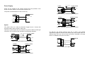
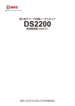
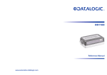
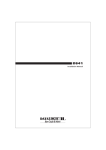
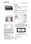
Special Instructions for
DS1100 SH2347 and DS2200 SH2348
10 - 30 Vdc
Electrical Connections
The scanner cable is equipped with a 25-pin female D-sub connector for
connection with the power supply and input/output signals:
Figure 1 – 25-pin female D-sub connector
25-pin D-sub connector pinout
Pin
9,13
25
1*
2, 21
3, 20
4
5
7
8
11
18
19
10, 12, 22
17
6, 14, 15, 16, 23, 24
Name
Function
VS
GND
CHASSIS
TXAUX
RXAUX
RTX485 RTX485 +
SGND
OUT1 +
OUT2 +
EXT TRIG +
EXT TRIG I/O REF
IN1 N.C.
Power supply input voltage +
Power supply input voltage Chassis Ground
TX RS232 Aux. Interface
RX RS232 Aux. Interface
RTX- RS485 Main Interface
RTX+ RS485 Main Interface
Signal Ground
Output 1 +
Output 2 +
External trigger +
External trigger Input/Output reference
Input 1 Not Connected
* Pins 1 and 25 are connected together internally.
851000292 (Rev. B)
Power Supply
Vext 30 Vdc max.
SCANNER
EXTERNAL TRIGGER
V
Power can be supplied to the scanner through the pins provided on the
25-pin connector used for communication with the host.
+ 5V
Signal
18 EXT TRIG+
19
EXT TRIG-
Ground
The power must be between 10 and 30 Vdc only.
SCANNER
VS
USER INTERFACE
13/9
GND
CHASSIS
V+ (10 - 30 Vdc)
25
Figure 4 - Input PNP command using external power
SCANNER
GND
9
1
+ 5V
Inputs
The yellow LED is on when the External Trigger forces a current flow
through the EXT TRIG+ and EXT TRIG- pins.
This input is optocoupled and can be driven by both an NPN or PNP type
command. The connections are indicated in the following diagrams:
SCANNER
+ 5V
Vext
18
EXT TRIG+
19
EXT TRIG-
EXTERNAL TRIGGER
30 Vdc max. EXTERNAL TRIGGER
V
Signal
VS
18
EXT TRIG+
19
EXT TRIG-
25
GND
9
+ 5V
VS
SCANNER
USER INTERFACE
13/9
VS
17
IN1 -
22
I/O REF
Ground
Figure 6 - IN1 - Input command
19 EXT TRIGGND
V
V
18 EXT TRIG+
25
Ground
For DS1100, the general purpose input IN1 is used in the Standard
Application Program to store the code verifier (see “Store Verifier HW” in the
WinHost Help On Line). Use the input connections indicated in the figure
below. For DS2200, this input is not used.
47 K
EXTERNAL TRIGGER
Signal
Figure 5 - Input PNP command using scanner power
Figure 2 - Input NPN command using external power
SCANNER
V
Signal
Ground
Figure 3 - Input NPN command using scanner power