1
SC6000
Reference Manual
SC6000
REFERENCE MANUAL
DATALOGIC S.p.A.
Via Candini 2
40012 - Lippo di Calderara di Reno
Bologna - Italy
SC6000 Reference Manual
Ed.: 10/2005
ALL RIGHTS RESERVED
Datalogic reserves the right to make modifications or improvements without prior notification.
Datalogic shall not be liable for technical or editorial errors or omissions contained herein, nor for
incidental or consequential damages resulting from the use of this material.
Product names mentioned herein are for identification purposes only and may be trademarks and or
registered trademarks of their respective companies.
© Datalogic S.p.A. 2003 - 2005
07/10/2005
CONTENTS
REFERENCES ............................................................................................................. v
Reference Documentation ............................................................................................ v
Services and Support ................................................................................................... v
SAFETY REGULATIONS ........................................................................................... vi
Power Supply............................................................................................................... vi
WEEE Compliance ...................................................................................................... vi
GENERAL VIEW ........................................................................................................ vii
GUIDE TO INSTALLATION ........................................................................................ ix
1
1.1
1.2
1.3
1.4
INTRODUCTION .......................................................................................................... 1
Product Description ...................................................................................................... 1
Model Description ......................................................................................................... 1
LED Indicators .............................................................................................................. 2
Accessories .................................................................................................................. 3
2
2.1
2.2
2.3
2.4
2.4.1
2.4.2
2.4.3
2.4.4
2.5
2.5.1
2.5.2
2.6
2.6.1
2.6.2
INSTALLATION ........................................................................................................... 4
Package Contents ........................................................................................................ 4
Overall Dimensions....................................................................................................... 5
Mechanical Mounting.................................................................................................... 6
Electrical Connections .................................................................................................. 8
Auxiliary Interface ......................................................................................................... 8
Ethernet Connector....................................................................................................... 9
DeviceNet Connector.................................................................................................. 11
Profibus Connector ..................................................................................................... 12
Typical Layouts........................................................................................................... 13
Standard Layout ......................................................................................................... 13
Fieldbus Network ........................................................................................................ 14
Keypad and Display.................................................................................................... 15
Standard Mode ........................................................................................................... 15
Menu Mode................................................................................................................. 16
3
3.1
3.2
3.2.1
3.2.2
3.3
3.4
SOFTWARE CONFIGURATION................................................................................ 17
Genius™ Installation................................................................................................... 17
Guide to Rapid Configuration for DS6000, DS8100A and DX8200A Slave Scanners17
Genius™ Network Setup Through Master.................................................................. 19
Alternative Slave Address Assignment....................................................................... 23
Guide to Rapid Configuration for DS8100 and DX8200 Slave Scanners ................... 23
Parameter Default Values........................................................................................... 27
4
4.1
MAINTENANCE ......................................................................................................... 31
Datalogic Automatic Replacement Procedure (DARPTM) ........................................... 31
5
TROUBLESHOOTING ............................................................................................... 33
6
TECHNICAL FEATURES........................................................................................... 35
A
ALTERNATIVE CONNECTIONS REFERENCE ........................................................ 36
Power Supply - I/O (Power/Net Connector)................................................................ 36
iii
Main Interface ............................................................................................................. 39
Extended I/O............................................................................................................... 41
Modem........................................................................................................................ 44
GLOSSARY................................................................................................................ 45
INDEX......................................................................................................................... 47
iv
REFERENCES
REFERENCE DOCUMENTATION
The documentation related to the SC6000 is listed below:
•
PWO power supply unit
•
Document about the Ethernet connectivity
•
Document about the Profibus connectivity
•
Guide to Installing a Redundant System
•
Replacing an SC8000 Controller
•
Help On-Line in PDF format
SERVICES AND SUPPORT
Datalogic provides several services as well as technical support through its website. Log on
to www.datalogic.com and click on the links indicated for further information including:
•
PRODUCTS
Search through the links to arrive at your product page where you can download specific
Manuals and Software & Utilities
•
SERVICES & SUPPORT
- Datalogic Services - Warranty Extensions and Maintenance Agreements
- Authorised Repair Centres
•
CONTACT US
E-mail form and listing of Datalogic Subsidiaries
v
SAFETY REGULATIONS
POWER SUPPLY
-
This product is intended to be installed by Qualified Personnel only.
WEEE COMPLIANCE
vi
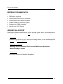
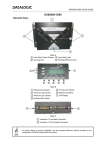
GENERAL VIEW
SC6000 Controller
4
3
5
2
1
6
Figure 1 - General View
1
Connector Panel
4
LCD Display
2
Connector Panel Legend
5
Status LEDs
3
Power On and Communication LEDs
6
Programming Keypad
vii
2
3
4
1
6
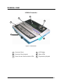
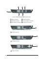
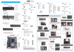
5
Figure 2 - SC6000-1200 Standard Model Connector Panel
1 Modem Connector
4 Ethernet Connector
2 Power/Net Connector
5 Auxiliary Interface Connector
3 Main Interface Connector
6 Extended I/O Connector
1
Figure 3 - SC6000-1211 Profibus Model Connector Panel
1 Profibus Connector
1
Figure 4 - SC6000-1215 DeviceNet Model Connector Panel
1 DeviceNet Connector
1
Figure 5 - SC6000-1230 Dual Ethernet Model Connector Panel
1 Ethernet Connector
viii
GUIDE TO INSTALLATION
The following can be used as a checklist to verify all the steps necessary to complete
installation of the SC6000 Controller.
1) Read all information in the section “Safety Precautions” at the beginning of this
manual.
2) Correctly mount the SC6000 using the bracket provided according to the information
in par. 2.3.
3) Connect the SC6000 Controller to the PWO by means of the appropriate accessory
cables (see par. 1.4).
4) Provide correct and complete system cabling through the PWO according to the
signals (Lonworks, encoder P.S., etc) necessary for the layout of your application.
(See subparagraphs under par. 2.4 and 2.5. See also the PWO Installation Manual).
5) Install the Genius™ configuration program onto a laptop PC from the CD-ROM
provided. Configure the SC6000 Controller by connecting this PC to the SC6000
Auxiliary port.
For configuration of a cluster of DS6000 family scanners, or DS8100A/DX8200A
scanners or both, see par. 3.2.
For configuration of a cluster of DS8100 or DX8200 scanners or both, see par. 3.3.
6) Execute the Backup procedure described in par. 4.1.
7) Exit the configuration program and run your application.
The installation is now complete.
ix
x
INTRODUCTION
1
1 INTRODUCTION
1.1 PRODUCT DESCRIPTION
The new SC6000 Controller offers all the necessary functions to make the phases of
installation, setup, testing, and maintenance of the omni-directional reading tunnel easy and
quick.
The SC6000 Controller key functions are:
•
•
•
•
Bus Controller: cluster management and Host interface of a multisided reading tunnel
based on Lonworks bus;
DARPTM (Datalogic Automatic Replacement Procedure) function: automatic procedure for
scanner and bus controller replacement;
Diagnostic indications on the reading station status, simple to be detected without any PC
needed. This indications, based on LEDs and display, offer to the maintenance staff all
the necessary information;
Easy remotization of all the reading station information, thanks to built-in Ethernet and
field bus connectivity, and a dedicated 9-pin connector for Modem connection.
The SC6000 Controller is based on a robust alloy case divided into two parts: on the upper
part there is the display, the keypad and the LEDs. The lower part contains the motherboard,
the removable Compact-Flash memory, the fieldbus boards and the connector panel.
The simple and sturdy mechanical structure makes the SC6000 Controller the ideal solution
for industrial environments.
The SC6000 Controller is fully compatible both with the 6000 family and with the 8000 family
(DS8100A and DX8200A) scanners. This means that the SC6000 Controller can work as a
bus controller for a cluster of DS6000 family scanners, or DS8100A/DX8200A scanners or
both.
The SC6000 Controller is also compatible with DS8100 and DX8200 (Lonworks versions). It
is not possible to mix DS8100/DX8200 with 6000 family or DS8100A/DX8200A.
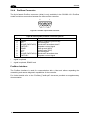
1.2 MODEL DESCRIPTION
The SC6000 Controller is available in versions that differ in regard to the following
characteristics:
SC6000 - 1XXX
200 = Standard
211 = Profibus
215 = DeviceNet
230 = Dual Ethernet
1
SC6000
1
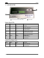
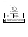
1.3 LED INDICATORS
2
1
Figure 6 - LEDs Description
2 Status LEDs
1 Power ON and Communication LEDs
System Signal LEDs
Name
Color
State
Function
Power ON
Green
Tx Data
Green
Rx Data
Green
Ethernet
Red
PS
Yellow
PS Aux
Yellow
Tach
Yellow
Network
Red
ON
OFF
Blinking
OFF
Blinking
OFF
ON
OFF
ON
OFF
ON
OFF
Blinking
OFF
ON
OFF
SC6000 Powered
No Power
Transmitting Data on MAIN
No Data Transmission
Receiving Data on MAIN
No Data Reception
Ethernet Line Connected
No Ethernet Line Connected
Presence Sensor Active
Presence Sensor Not Active
Presence Sensor Active
Presence Sensor Not Active
Encoder Active
Encoder Not Active
Lonworks OK
Lonworks Error
System Event Status LEDs
Name
Color
State
Function
Warning
Red
Status OK
Green
ON
OFF
ON
OFF
Scanner Cluster Failure
Scanner Cluster OK
Controller Status OK
Controller Failure
2
INTRODUCTION
1
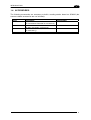
1.4 ACCESSORIES
The following accessories are necessary to build a reading station based on SC6000 (the
scanner-related accessories are not included):
Name
Description
Part Number
CAB-SC6003
25p cable SC6000 to PWO, 3 m
(for Power/Net & Extended I/O connections)
9p cable SC6000 to PWO, 3 m
(for Main and Modem connections)
17p cable PWO to PWO, 3 m
(for redundancy)
Power&Connect system, 480W
93A051293
CAB-SC6103
CAB-PWO 03
PWO-480
93A051294
93A051295
93ACC1767
3
SC6000
2
2 INSTALLATION
To install the system follow the given procedure:
1)
Select the mounting location and mount the SC6000 Controller;
2)
Mount the PWO (refer to the PWO Installation Manual);
3)
Proceed with system electrical connections;
4)
Install the GENIUS™ program on the configuration PC.
If your system requires the SC6000 to be connected to PWO refer to the
Reference Documentation section for details.
NOTE
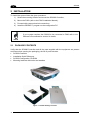
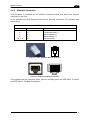
2.1 PACKAGE CONTENTS
Verify that the SC6000 Controller and all the parts supplied with the equipment are present
and intact when opening the packaging; the list of parts includes:
• SC6000 Controller
• Installation Quick Reference
• SC6000 Configuration CD-ROM
• Mounting brackets with knobs and washers
Figure 7 - SC6000 Package Contents
4
INSTALLATION
2
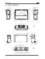
2.2 OVERALL DIMENSIONS
39.7
[1.56]
124.4
[4.90]
99.7
[3.93]
MØ8
248.7
[9.79]
124.4
[4.90]
39.7
[1.56]
80.2
[3.16]
319.5
[12.58]
298
[11.73]
mm
inch
Figure 8 - SC6000 Overall Dimensions
N°
[R 2 R
0.
1
59 5
]
300
[11.80]
48
[1.89]
16
[0.63]
N°6 8
[0.32]
N°2 R10
[R0.39]
180
[7.09]
50
[1.97]
5
[0.20]
30
[1.18]
16
[0.63]
15
[0.59]
M8
309
[12.17]
85
[3.35]
85
[3.35]
mm
inch
40
[1.57]
48
[1.89]
40
[1.57]
40
[1.57]
56
2Ø
N° 2.22]
[Ø
[0 8
.3
3]
15
[0.59]
95
[3.74]
50
[1.97]
8
2Ø
N° .33]
[Ø0
80
[3.15]
20
[0.79]
Figure 9 - ST-222 Bracket Overall Dimensions
5
SC6000
2
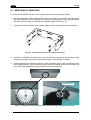
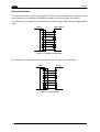
2.3 MECHANICAL MOUNTING
To mount the SC6000 Controller on the reading station frame proceed as follows:
1
Mount the bracket on the reading station frame: the slots on the bracket will help obtain
the best positioning. When working in environments characterized by strong vibrations,
set the screws as close as possible to the bracket edges, see Figure 10.
2
Tighten the ST-222 bracket to the reading station frame using the screws and washers.
Figure 10 - Mounting the bracket on the reading station frame
3
Position the SC6000 Controller at the top of the bracket: make sure the two large round
openings coincide to the ones located at the edges of the SC6000 Controller.
4
While supporting the SC6000 Controller, rotate the whole device until it is aligned for the
best viewing position, then insert the set pin screw with locking washer until it inserts into
one of the small positioning holes located on the terminal bracket.
Set pin screw
Figure 11 - SC6000 Controller Side View with Punched Steel Ring and Relative Set Pin Screw
6
INSTALLATION
2
The specially punched steel ring has been designed to obtain the most precise rotation
possible in terms of angle calibration, steadiness and consequent absence of torque
between both sides of device.
5
Place a locking washer and then a flat washer onto each knob. Tighten the SC6000
Controller to its bracket by screwing the knobs into their holes - one on each side.
Figure 12 - Mounting the SC6000 Controller on the bracket
The SC6000 Controller can rotate on its mounting bracket up to 90° with respect to the
mounting bracket position. See figure below for suggested positions:
Figure 13 - Suggested Mounting Positions
7
SC6000
2
2.4 ELECTRICAL CONNECTIONS
The connectors available for each scanner model are the following:
Scanner Model
All models
-
1230
1211
1215
2.4.1
Connector
Power/Net
Type
25-pin male power supply, lonworks and
input/output signals
25-pin female extended I/O signals (optoisolated)
9-pin male modem connection
9-pin female RS232/RS485 main serial connection
9-pin female RS232 auxiliary connection
RJ45 modular Ethernet network
RJ45 modular Ethernet network
9-pin female Profibus network
5-pin male DeviceNet network
Extended I/O
Modem
Main
Aux
Eth-1
Eth-2
Profibus
DeviceNet
Auxiliary Interface
The auxiliary serial interface is equipped with RS232 interface connections. The interface
can be enabled or disabled through the Genius™ configuration program.
The following pins of the 9-pin connector are used for RS232 interface connection:
Pin
2
3
5
Name
TX
RX
GND
9-pin D-sub Female Connector Pinout
1
5
Function
Transmit
Receive
9
6
Ground
9-pin D-sub Female Connector
USER INTERFACE (Laptop)
SC6000
3
RXAUX
2
TXAUX
5
GND
TXD
RXD
Signal Ground
Shield
Figure 14 - RS232 Auxiliary Interface Connections
8
INSTALLATION
2.4.2
2
Ethernet Connector
This connector is available for all SC6000 Controller models and allows the Ethernet
connection to the host.
In the SC6000-1230 Dual Ethernet there are two Ethernet connectors for secondary host
connections.
RJ45 Modular Jack Pinout
Pin
1
2
3
6
4, 5, 7, 8
Name
TX +
TX RX +
RX N.C.
Function
Transmitted data (+)
Transmitted data (-)
Received data (+)
Received data (-)
Not connected
8
1
Figure 15 – Cable RJ45 Male Modular Connector
1
8
Figure 16 – RJ45 Female Modular Connector
This interface and the connector pinout (see the following table) are IEEE 802.3 10 BaseT
and IEEE 802.3u 100 BaseTx compliant.
9
SC6000
2
Ethernet Interface
The Ethernet interface (NIC) can be used for TCP/IP communication with a remote or local
host computer by connecting the SC6000 Controller to a LAN or directly to a host PC.
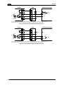
The following is an example of a connection to a LAN through a Hub using a straight through
cable:
SC6000
HUB / SWITCH
TX+
1
1
TX-
2
2
RX+
3
3
n. c.
4
4
n. c.
5
5
RX-
6
6
n. c.
7
7
n. c.
8
8
n. c. = not connected
Figure 17 – Straight Through Cable
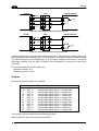
The following is an example of direct connection to a PC using an inverted cable:
Host PC
SC6000
TX+
1
3
TX-
2
6
RX+
3
1
n. c.
4
4
n. c.
5
5
RX-
6
2
n. c.
7
7
n. c.
8
8
n. c. = not connected
Figure 18 – Inverted Cable
10
INSTALLATION
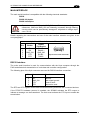
2.4.3
2
DeviceNet Connector
The 5-pin male connector is only available in the SC6000-1215 DeviceNet model and allows
connection between the host and the controller:
4
3
1
2
5
Figure 19 - DeviceNet 5-pin Male Connector
5-pin DeviceNet connector pinout
Pin
2
5
1
4
3
NOTE
Name
V+
CAN_L
SHIELD
CAN_H
V-
Function
Supply voltage – positive pin
CAN bus data line – L
Shield
CAN bus data line – H
Supply voltage – negative pin
The power supplied on pin V+ and V- is used only to propagate power to
the section of the DeviceNet board directly connected to the Bus. It is
completely isolated from the SC6000 power, which must be supplied on
pin 16 and pin 3, 4 of the 25-pin Power/Net connector.
11
SC6000
2
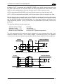
2.4.4
Profibus Connector
The 9-pin female Profibus connector (white) is only available in the SC6000-1211 Profibus
model and allows connection between the host and the controller:
1
5
9
6
Figure 20 - Profibus 9-pin Female Connector
9-pin D-sub Female Profibus connector pinout
Pin
1
2
3
4
5
6
7
8
9
Name
Shield*
N.C.
B-LINE (RxD/TxD-P)
CNTR-P**
DGND
+5 V
N.C.
A-LINE (RxD/TxD-N)
CNTR-N**
*
signal is optional
**
signal is optional; RS485 level
Function
Shield, protective ground resp.
Not connected
Received/Transmitted data-P
Repeater control signal
Data ground (M5V)
Voltage plus (P5V)
Not connected
Received/Transmitted data
Repeater control signal
Profibus Interface
The Profibus interface is used for communication with a Host and allows expanding the
networking and remote diagnostic capabilities of the controller.
For further details refer to the “Profibus_Fam6k.pdf” document provided as supplementary
documentation.
12
INSTALLATION
2
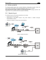
2.5 TYPICAL LAYOUTS
The following typical layouts refer to system hardware configurations, but also require the
correct setup of the software configuration parameters (see par. 3.2 for details).
Other layouts require the use of a specific SC6000 Controller model.
The accessories and cables indicated in the following figures are Datalogic products. We
suggest their use to guarantee the correct system functioning.
2.5.1
Standard Layout
For Standard layouts the following connections can be made:
•
Ethernet direct or through Hub;
•
point-to-point on the Main interface using either RS232 or RS485 full-duplex
communications to Host;
•
directly to a modem for remote Host communications.
Figure 21 - Ethernet Connection
Figure 22 - Main Connection
13
SC6000
2
Figure 23 - Modem Connection
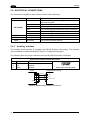
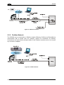
2.5.2
Fieldbus Network
The SC6000 can be connected to a Fieldbus network (Ethernet, Profibus and DeviceNet) to
communicate with a remote host (for example, remote PC connected via Internet).
Connections are made directly through cables to the Fieldbus connector and do not require
any converter or adapter.
Figure 24 - Fieldbus Network
14
INSTALLATION
2
Figure 25 - Dual Ethernet Connection
2.6 KEYPAD AND DISPLAY
The SC6000 keypad allows entering a menu to select one of the functions described in the
following paragraphs.
2.6.1
Standard Mode
Upon startup, the diagnostic mask window is visualized by default. Using the UP and DOWN
keys it is possible to scroll the other windows following this order:
1)
2)
3)
4)
5)
Diagnostic Mask Window
Performance Window
Reading Mask Window
I/O Status Window
System Info Window
Diagnostic Mask Window (Default Window)
This window illustrates the status of each node (of each scanner of the cluster) according to
the following convention:
"-"
"?"
"
"
"
"
From the startup the node NID has not been discovered.
At the startup of the system the NID has been discovered but the node does not
answer to the master.
* " The node status is OK.
! " The node returns an error code to the diagnostic Laser Off.
& " The node returns an error code to the diagnostic Motor Off.
% " The node is in monitor mode.
15
SC6000
2
Reading Performance Window
This window displays the following data:
•
Number of the processed parcels
•
Good Read Rate
•
No Read Rate
•
Multiple Read Rate
Reading Mask Window
This window indicates the node that performed a reading of the codes enabled on the
master.
The following indicators are used:
"*"
"-"
The node read a barcode enabled on the master.
The node read no barcode.
I/O Status Window
This window provides data concerning the conveyor speed and the digital input/output status.
System Info Window
This window provides information about the software release.
2.6.2
Menu Mode
For security purposes, the menu mode is entered by pressing the ENTER and MENU keys at
the same time.
Through this menu, it is possible to perform the following:
•
Main Parameter Setting: IP address, Netmask, Gateway address; Profibus address
(for Profibus models); DeviceNet address (for DeviceNet models); supplementary
IP address, supplementary Netmask, and supplementary Gateway address (for
Dual Ethernet models).
These parameters may be set through the Genius™ program (see chapter 3 for
details).
16
•
Date&Time setting;
•
DARP™ (Datalogic Automatic Replacement Procedure);
•
CASP™ (Cluster AutoSetup Procedure): this procedure allows automatic address
assignment to the scanner cluster nodes. This operation can also be performed by
starting up the system while pressing the SETUP key.
SOFTWARE CONFIGURATION
3
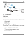
3 SOFTWARE CONFIGURATION
3.1 GENIUS™ INSTALLATION
Genius™ is a new Datalogic scanner configuration tool providing several important
advantages:
• Multi-language version;
• Defined configuration directly stored in the device;
• Communication protocol independent from the physical interface allowing to consider the
device as a remote object to be configured and monitored.
To install Genius™, proceed as follows:
1) Turn on the PC that will be used for configuration (Windows 95/98 or NT);
2) Insert the Genius™ CD-ROM;
3) Wait for the CD to autorun and follow the installation procedure.
When running Genius™, the procedure for setting the parameters is supported by a help online, which is displayed in an HTML browser. It can be selected from the Configuration Help
option available in the Help menu. In addition, a context-sensitive help can be enabled by
pressing the <F1> key after selecting the desired parameter.
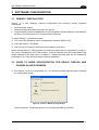
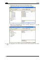
3.2 GUIDE TO RAPID CONFIGURATION FOR DS6000, DS8100A AND
DX8200A SLAVE SCANNERS
1. Run Genius™ from the configuration PC. The following window appears asking to select
the configuration mode.
Figure 26 - Genius™ Wizard Opening Window
Select Advanced. The Wizard option is not currently available for SC6000.
17
SC6000
3
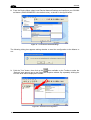
2. From the Device Menu select Local Device Network Settings and configure your SC6000
as Master (SYNCHRONIZED is the default value), as shown in the figure below:
Figure 27 – Local Device Network Settings
The following dialog box appears asking whether to send the configuration to the Master or
not:
icon available on the Toolbar to make the
3. Click the "Yes" button, then click on the
“Devices” area appear next to the Parameter Explorer window. By repeatedly clicking the
icon this area will be displayed or hidden.
Figure 28 – View Device Configuration
18
SOFTWARE CONFIGURATION
3
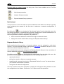
Each device is indicated by the following graphical objects:
•
•
•
check box allowing to select/deselect a specific device to perform the desired
operations (i.e. program downloading);
icon representing the device status;
a label reporting information transmitted by the device when connected (the device
address, generated errors, device description).
4. Then, proceed with the Network Setup (par. 3.2.1).
5. Configure the SC6000 and Slave Scanner parameters according to your application
using the configuration window in Genius™ for each device. The main steps are:
•
Configure the PackTrack parameters
•
Select the codes to be read
•
Set-up the communication parameters
•
Define data formatting parameters
6. Send the configuration to the Slave Scanners from the Send command in the Device
Menu.
7. Perform a DARP™ backup by clicking the relative icon in the Device Network area.
3.2.1
Genius™ Network Setup Through Master
Network Setup allows configuring your Local Lonworks Network through the Master using
Genius™.
Three different procedures are available to define the number of network slave scanners,
their label and address according to two main conditions:
Condition
Available Procedure
Feature
Unknown Slave Addresses
Net-Autoset
automatically assigns random addresses to
slave or Stand Alone scanners.
Known Slave Addresses
Network Wizard
customizes the network (slave label and
address definition and physical identification
of a specific slave within network), updates
configuration to a file and makes it ready to
be sent to the Master.
Express Network Setup
automatically performs all the operations of
the Network Wizard apart from the physical
identification of a specific slave scanner.
The Network Setup procedure as described requires Genius™ software
version 1.06 or later. In addition, the Net-Autoset procedure requires
scanner software version 6.40 or later.
NOTE
19
SC6000
3
Proceed with the network setup by using one of the icons available on the Tool Bar
according to the procedure to follow:
=
Net-Autoset procedure
=
Network Wizard procedure
=
Express Network Setup procedure
Net-Autoset
This procedure is to be used when all scanner addresses and labels are unknown (typically
when configuring the network for the first time or whenever a network reconfiguration is
required).
By clicking the
icon or selecting the "Net_Autoset" option from the right-click menu, the
Net-Autoset procedure is started allowing automatic assignment of random addresses to all
slave or Stand Alone scanners connected within the network.
Once the procedure has been completed, it is possible to:
•
define customized addresses and labels through the Network Wizard;
•
display the scanner default labels through the Express Network Setup.
Express Network Setup
Before performing this procedure, a Lonworks address must be assigned to each slave
scanner. The most practical method is through the Net-Autoset procedure. See par. 3.2.2 for
alternative address assignment methods.
Once all addresses have been assigned, the Express Network Setup is to be used when all
scanner addresses and labels do not need to be modified.
icon or by choosing the related option from the right-click menu, the
By clicking on the
procedure is started which automatically performs the following operations:
-
opening the wizard;
-
polling the network to discover connected scanners;
-
transferring all scanners found to the "Requested Devices" area of the wizard where
your network customization is defined;
-
saving the new network configuration;
Once the procedure has been completed, a dialog box will appear asking whether to send
the configuration to the Master. Choose the “Yes” option to start this procedure.
20
SOFTWARE CONFIGURATION
3
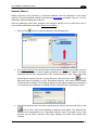
Network Wizard
Before performing this procedure, a Lonworks address must be assigned to each slave
scanner. The most practical method is through the Net-Autoset procedure. See par. 3.2.2 for
alternative address assignment methods.
Once all addresses have been assigned, the Network Wizard is to be used when one or
more scanner addresses and labels need to be modified.
1. Click on the
button to open the Network Wizard dialog box:
a. if the slave scanners have already been configured and wired to the network, click on
the Autodetect button to start a polling procedure of the current network. All slave
scanners found will be represented in the “Current Devices” area. Then, select the
desired slave scanner from the “Current Devices” area and click on the
icon (or
drag and drop) to transfer it to the “Requested Devices” area where your network
customization is defined. The following dialog box will appear allowing (if necessary)
to change the slave address ("Available Device" field) and label ("Description" field):
b. if the slave scanners have not been configured and wired to the network, click on the
icon to add a new device defining its address and model. The added slave
scanner will be displayed in the “Requested Devices” area. This option in any case
requires that all slave scanners have their address set before the network can
function.
21
SC6000
3
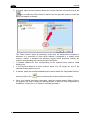
2. If desired, select a slave scanner within the "Current Devices" area and click on the
icon (or select the "Show Device" option from the right-click menu) to make the
dialog box appear as follows:
•
•
The "Show Device" option is particularly useful after the Net-Autoset procedure or
whenever it is necessary to know which address is assigned to a specific slave
scanner. Indeed, it activates the following signals which physically indicate the
scanner corresponding to the one selected, in particular:
in Network Wizard the icon corresponding to the selected slave scanner starts
blinking red;
in the Physical Network all slave scanner lasers turn off except the one of the
selected scanner which turns on.
3. If desired, select the transferred/added slave scanner within the “Requested Devices”
area and click on the
icon to customize the scanner label and address.
4. Once your network has been customized, close the network wizard. Before closure,
the program will show a dialog box asking whether to send the new configuration to
the Master. Choose the “Yes” option to start this procedure.
22
SOFTWARE CONFIGURATION
3.2.2
3
Alternative Slave Address Assignment
As alternatives to Network Setup through the Master, each Slave scanner can be assigned
an address through the following methods:
•
random address assignment from SC6000 to all slaves in the network by performing
the CASP™ procedure as described in par. 2.6.2;
•
address setting through the Local Device Network Settings item in the Device Menu
with the slave scanner connected to Genius™;
•
manual address setting through slave scanner keyboard (see par. “Internal Net” in the
relative Scanner Reference Manual for details);
3.3 GUIDE TO RAPID CONFIGURATION FOR DS8100 AND DX8200
SLAVE SCANNERS
1) Connect to each scanner Debug port and set a Lonworks Node address which must be
different and consecutive (i.e. 1, 2, 3, 4, etc.).
2) Make all the necessary PackTrack parameter settings.
3) Run Genius™ from the configuration PC. The following window appears asking to select
the configuration mode.
Figure 29 - Genius™ Wizard Opening Window
Select Advanced. The Wizard option is not currently available for SC6000.
23
SC6000
3
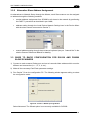
4) From the Device Menu select Local Device Network Settings and configure your SC6000
as Other, as shown in the figure below:
Figure 30 – Local Device Network Settings
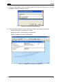
5) From the Reading System Layout folder and configure the following parameters:
Device Assignment = Controller Lon Old8K
Number of Slaves = according to your application
Check the Modify Lon Slave Configuration
Figure 31 – SC6000 Device Assignment Configuration
24
SOFTWARE CONFIGURATION
3
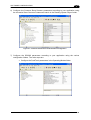
6) Configure the Common Slave Scanner parameters according to your application using
the Lonworks Slave Common Parameters branch in the Reading System Layout folder.
Figure 32 – Common Slave Scanner Code Selection Configuration
7) Configure the SC6000 parameters according to your application using the various
configuration folders. The main steps are:
• Configure the PackTrack parameters in the Operating Modes folder
25
SC6000
3
• Selecting the codes to be read in the Code Definition folder
(they must be the same as those set for the slave scanners)
• Set-up the communication and data formatting parameters in the Data
Communications settings folder
8) Send the configuration to the Slave Scanners from the Send command in the Device
Menu.
26
SOFTWARE CONFIGURATION
3
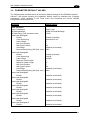
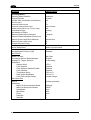
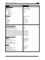
3.4 PARAMETER DEFAULT VALUES
The following table contains the list of the factory default settings for the SC6000 Controller.
Genius™ also allows checking the parameter default values by selecting the "Compare
parameters" option available in the Tools menu and comparing the current SC6000
configuration to the default one.
Parameter
Code Definition
Code Combination
No Read Message
No Read String (128 characters max)
Code Label Settings#1
Enable
Code Symbology
Label Length
Min Code Position
Max Code Position
CheckDigit
Pattern Match String (200 char. max)
Code Label Settings#2
Enable
Code Symbology
Label Length
Minimum Label Length
Maximum Label Length
Min Code Position
Max Code Position
CheckDigit
Pattern Match String (200 char. max.)
Code Label Settings#3
Enable
Code Label Settings#4
Enable
Code Label Settings#5
Enable
Code Label Settings#6
Enable
Code Label Settings#7
Enable
Code Label Settings#8
Enable
Code Label Settings#9
Enable
Code Label Settings#10
Enable
Default Setting
Single Label
Global No Read Message
<CAN>
Enabled (checked)
Interleaved 2 of 5
8
0
255
Disabled (unchecked)
NULL
Enabled (checked)
Code39
Variable
1
60
0
255
Disabled (unchecked)
NULL
Disabled (unchecked)
Disabled (unchecked)
Disabled (unchecked)
Disabled (unchecked)
Disabled (unchecked)
Disabled (unchecked)
Disabled (unchecked)
Disabled (unchecked)
27
SC6000
3
Parameter
Operating Modes
Operating Mode Selection
Physical Encoder
Encoder Step (hundredths of millimeter)
PS Line (mm)
Presence Sensor Input
Presence Sensor Input Level
Distance from PS Line to Tx Line (mm)
Transmission Edge
Max Number of Packs
Minimum Distance Error Behavior
Minimum Distance Between Packs (mm)
Minimum Pack Length Error Behavior
Minimum Pack Length (mm)
Window Dimension (mm)
Reading System Layout
Device Assignment
Data Communication Settings
Host Application Protocol Type
Data Format
Header TX Start
Termination After No Read Message
Message TX Trigger Selection
Parameters
Header String
Code Position
Code Direcion Identifier Enable
Code Identifier
Termination String
Data Packet Separators
Code Field Length Setting
Main Serial Port
Data TX
Parameters
Main Port Communication Mode
Main Port Electrical Interface
Handshake
Baud Rate
Parity
Data Bits
Stop Bits
28
Default Setting
Packtrack
Enabled
100
0
PS
Active Closet
100
Leading
10
Compose
30
Discard Item
50
15
Master (Synchronized)
Standard
With Data
Enabled
On Decoding
<STX>
Disabled
Disabled
Disabled
<CR><LF>
<CR><LF>
Variable Length
Enabled (checked)
Standard
RS232
None
9600
None
8
1
SOFTWARE CONFIGURATION
Parameter
Auxiliary Serial Port
Data TX
Pass Through
Parameters
Baud Rate
Parity
Data Bits
Stop Bits
Ethernet Port
Status
Eth_speed
DHCP
IP_address
IP_netmask
IP_gateway
IP_dns1
IP_dns2
Digital I/O Settings
Digital Input Lines Settings
Debouncing for Input 1, 2 and 3
Debouncing for Encoder
Debouncing for PS and PSAUX
PS Active Level Overridden by Op. Mode
Encoder Active Level Overridden by Op. Mode
PSAUX Active Level Overridden by Op. Mode
Input 1 Active Level Overridden by Op. Mode
Input 2 Active Level Overridden by Op. Mode
Input 3 Active Level Overridden by Op. Mode
Digital Output Lines Setting
Output 1
Line State
Activation Event
Alternative Activation Event
Deactivation Event
Alternative Deactivation Event
Deactivation Timeout (ms)
Output 2
Line State
Activation Event
Alternative Activation Event
Deactivation Event
Alternative Deactivation Event
Deactivation Timeout (ms)
3
Default Setting
Enabled (checked)
Disabled (checked)
115200
None
8
1
Enabled (checked)
Auto
Disabled
172.16.11.221
255.255.0.0
172.16.0.254
172.16.0.21
0.0.0.0
5 ms
500 µs
5 ms
Active Closed
Active Closed
Active Closed
Active Closed
Active Closed
Active Closed
Normally Open
Complete Read
Multiple Read
Timeout
None
50
Normally Open
No Read
Partial Read
Timeout
None
50
29
SC6000
3
Parameter
Output 3
Line State
Activation Event
Alternative Activation Event
Deactivation Event
Alternative Deactivation Event
Output 4
Line State
Activation Event
Alternative Activation Event
Deactivation Event
Alternative Deactivation Event
Output 5
Line State
Activation Event
Alternative Activation Event
Deactivation Event
Alternative Deactivation Event
Output 6
Line State
Activation Event
Alternative Activation Event
Deactivation Event
Alternative Deactivation Event
Diagnostics
Statistics
30
Default Setting
Normally Open
None
None
None
None
Normally Open
None
None
None
None
Normally Open
None
None
None
None
Normally Open
None
None
None
None
Disabled (unchecked)
Disabled (unchecked)
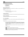
MAINTENANCE
4
4 MAINTENANCE
4.1 DATALOGIC AUTOMATIC REPLACEMENT PROCEDURE (DARPTM)
Once the system configuration has been completed, launch the DARP™ backup by one of
the following methods:
Using Genius:
Click on the DARP™ backup icon in the Device Network area. You will be prompted to select
the desired backup option (complete, all scanners, controller, or each single scanner).
Using the SC6000 keypad:
1. Press the <Ent> and <Menu> keys simultaneously to enter the Menu;
2. Use the <arrow> keys to move within the menu items;
3. In the <System> menu choose <Backup> and select the desired backup option
(complete, all scanners, controller, or each single scanner).
The SC6000 Controller will store the complete system configuration on the Compact Flash
card.
If a slave scanner has to be replaced, the corresponding configuration (node address, code
configuration, PackTrack™ configuration, etc.) is automatically downloaded by the SC6000
into the new scanner at the next system startup.
Systems with DS8100 or DX8200 slave scanners must have been
installed according to the procedure in par. 3.3.
NOTE
In case of SC6000 failure, the complete system configuration can be recovered from the
damaged SC6000 Compact Flash: by simply installing the old Compact Flash in the new
SC6000, the system configuration is automatically restored and the reading station is ready
to start working again.
Before removing the Compact Flash card, switch the SC6000 Controller off.
CAUTION
31
SC6000
4
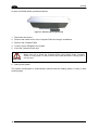
In case of SC6000 failure proceed as follows:
Figure 33 - Removing the Compact Flash
1. Disconnect the device
2. Remove the rubber cover of the Compact Flash slot using a screwdriver
3. Remove the Compact Flash
4. Connect a new SC6000 to the system
5. Insert the Compact Flash card
CAUTION
Make sure not to insert the Compact Flash card upside down. Carefully
insert it in the guides, so that it will not fall inside the device. Gently push it
into the slot.
6. Start up the system
The system configuration is automatically restored and the reading station is ready to start
working again.
32
TROUBLESHOOTING
5
5 TROUBLESHOOTING
NOTE
Before contacting your local Datalogic office or Datalogic Partner or ARC,
it is suggested to save the device configuration to a *.ddc file by means of
the Genius™ software configuration program and check the exact device
model and serial number.
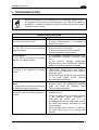
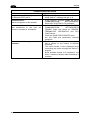
TROUBLESHOOTING GUIDE
Problem
Power On:
the “Power On” LED is not lit.
On Line Mode 1:
the "PS” LED is not lit (when external
trigger activates).
On Line Mode 1:
the "PS” LED is correctly lit but nothing
happens (no reading results).
Serial On Line Mode:
the reader is not triggered (no reading
results).
Suggestion
• Is power connected?
• If using a power adapter, is it connected to
PWO 25-pin cable?
• Check carefully if you are referring to the
25-pin connector of the PWO.
• Is sensor connected to PWO PS input?
• Is power supplied to photo sensor?
• Is the software configuration consistent with
the application condition (operating mode,
etc.)?
In the Genius™ software configuration
program select the OPERATING MODES
folder and check for related parameters.
• In the Genius™ program select the
OPERATING MODE folder and check if
serial on line is enabled as “On Line options”
parameter value.
• Are the Start-Stop strings correctly assigned?
• Is the serial trigger source correctly
connected and configured)?
• In the Genius™ software configuration
program select the OPERATING MODES
folder and check the “Reading Phase
Timeout” parameterization.
On Line Mode and Serial On Line
Mode:
the reader does not respond correctly to
the expected external signal end.
•
Communication (Main / Aux):
the device is not transmitting anything to •
the host.
•
•
•
Is serial Main / Aux cable connected?
Is wiring correct?
If using the Main RS232 or RS485 interface,
is the reference ground connected to
GND_ISO? Be careful that it is not
completely different from GND power ground.
Are serial host settings equivalent to serial
device setting?
When using the Main interface, Tx Data and
Rx Data LEDs must be lit during data
transfer.
33
SC6000
5
TROUBLESHOOTING GUIDE
Problem
Communication (Ethernet):
the Ethernet LED is not lit.
Communication:
data do not appear on the terminal.
Suggestion
• Verify the HUB connection.
• Verify Genius™ settings (see par. 3.4).
• In the Genius™ program enable the DATA
COMMUNICATION
SETTINGS/MAINAUXILIARY PORT\DATA TX parameter.
• In the Genius™ program select the DATA
Communication:
COMMUNICATION
SETTINGS/DATA
data transferred to the host are
FORMAT folder and check for HEADER,
incorrect, corrupted or incomplete.
TERMINATOR, SEPARATOR and FILL
CHAR values.
• Check the CODE FIELD LENGTH value.
• Are the COM port parameters correctly
assigned?
How do I obtain my units’ serial • The device serial number is printed on a label
that is affixed on the bottom of SC6000
numbers?
Controller.
• The serial number is also displayed when
connecting the device through the Genius™
program.
• Serial numbers consist of 9 characters: one
letter, 2 numbers, another letter followed by 5
numbers.
34
TECHNICAL FEATURES
6
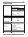
6 TECHNICAL FEATURES
ELECTRICAL FEATURES
Supply voltage
Power consumption
Communication Interfaces
15 to 30 Vdc
6.5 W typical
9 W Max. (including startup current)
Main (isolated)
Modem
RS232
RS485 full-duplex
Auxiliary
RS232
RS232
Other
Inputs (optocoupled NPN or PNP)
Outputs (optocoupled)
USER INTERFACE
LCD Display
Keypad
LED indicators
SOFTWARE FEATURES
Configuration modes
Parameter storage
ENVIRONMENTAL FEATURES
Operating temperature
Storage temperature
Humidity
Vibration resistance
Lonworks
1,25 Mb/s
Ethernet
10 or 100 Mb/s
DeviceNet
125 or 250 Kb/s
Profibus
12 Mb/s
Encoder, PS, PS Aux, 3 polarity insensitive
optocoupled inputs
6 optocoupled outputs, 3 relay control outputs
4 lines by 20 characters LCD
6 keys
PS Aux
Power ON
TACH
TX data
Networks
RX data
Controller
Ethernet
Scanners
PS
Genius™ utility program
Non-volatile extractable FLASH card
Protection class
0° to +50 °C (+32° to +122 °F)
-20° to +70 °C (-4° to +158 °F)
90% non condensing
IEC 68-2-6 test FC
14 mm @ 2 to 10 Hz; 1.5 mm @ 13 to 55 Hz;
2G @ 70-200 Hz; 2 hours on each axis
IEC 68-2-27 test EA
30 G; 11 ms;
3 shocks on each axis
IP64*
PHYSICAL FEATURES
Mechanical dimensions
Weight
320 x 250 x 90 mm (12.6 x 9.84 x 3.54 in)
3.3 kg. (7.26 lb)
Shock resistance
*with Harting RJ Industrial push pull Ethernet connector.
35
SC6000
A
A
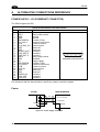
ALTERNATIVE CONNECTIONS REFERENCE
POWER SUPPLY - I/O (POWER/NET CONNECTOR)
The PWO supplies 24 VDC.
25-pin D-Sub Female Connector Pinout
Pin
1
2
3
4
5
6
7
8
9
10
11
12
13
14
15
16
17
18
19
20
21
22
23
24
25
Name
REL1
REL3
GND
GND
ENCODER A
PS_AUX A
PS A
SYS_ENC_I/O
RES
RES
SHIELD_OUT
LON_OUT B
LON_OUT A
REL2
RES
VS
ENCODER B
PS_AUX B
PS B
SYS_I/O
RES
RES
SHIELD_IN
LON_IN B
LON_IN A
Function
Relay output control
Relay output control
Ground
Ground
Encoder (Tach)
Presence sensor aux.
Presence sensor
System signal
Reserved
Reserved
Lonworks
Lonworks
Lonworks
Relay output control
Reserved
Supply voltage
Encoder (Tach)
Presence sensor aux
Presence sensor
System signal
Reserved
Reserved
Lonworks
Lonworks
Lonworks
1
13
14
25-pin Male D-sub Connector
Pin references with the denomination A and B are polarity insensitive signals.
Power
USER INTERFACE
SC6000
16
3, 4
Shield
VS
GND
V+ (15 - 30 Vdc)
V- (Ground)
Chassis
Figure 34 – Power Supply Connection
36
25
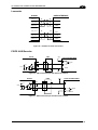
ALTERNATIVE CONNECTIONS REFERENCE
A
Lonworks
USER INTERFACE
SC6000
LON_IN A
25
25
LON A
LON_IN B
24
24
LON B
SHIELD_IN
23
23
SHIELD
LON_OUT A
13
13
LON A
LON_OUT B
12
12
LON B
SHIELD_OUT
11
11
SHIELD
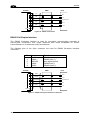
Figure 35 – SC6000 Lonworks Connection
PS/PS AUX/Encoder
PWO
SC6000
Vext
PS/PS AUX/ENCODER
V
Signal
A/B
+ 5V
+
PSIN
~
~
B/A
Ground
Figure 36 - PNP Command Input with Electrical Isolation
SC6000
PWO
A/B
+ 5V
PSIN
+
~
~
Vext
PS/PS AUX/ENCODER
V
-
B/A
Signal
Ground
Figure 37 - NPN Command Input with Electrical Isolation
37
SC6000
A
SC6000
PWO
VS
PS/PS AUX ENCODER
VS
V
VS_INPUTS*
Signal
A/B
+ 5V
+
PSIN
~
~
-
B/A
Ground
GND
*VS_INPUTS is connected through the 25-pin Extended I/O connector. If this connector is not used, VS_INPUTS
must be wired from one of the scanner terminals inside PWO, see the PWO Reference Manual for details.
Figure 38 - PNP Command Input Using System Power
SC6000
PWO
VS
VS_INPUTS*
PS/PS AUX ENCODER
VS
V
A/B
+ 5V
PSIN
+
~
~
-
B/A
Signal
GND
Ground
*VS_INPUTS is connected through the 25-pin Extended I/O connector. If this connector is not used, VS_INPUTS
must be wired from one of the scanner terminals inside PWO, see the PWO Reference Manual for details.
Figure 39 - NPN Command Input Using System Power
38
ALTERNATIVE CONNECTIONS REFERENCE
A
MAIN INTERFACE
The main serial interface is compatible with the following electrical standards:
RS232
RS485 full-duplex
RS485 half-duplex
CAUTION
Do not connect GND and GND_ISO to different (external) ground
references. GND and GND_ISO are internally connected through filtering
circuitry which can be permanently damaged if subjected to voltage drops
over 0.8 Vdc.
Details regarding the connections and use of the main interface selection are given in the
next paragraphs.
9-pin D-sub Female Connector Pinout
Pin
RS232
RS485
Full Duplex
2
3
5
7
8
TX
RX
GND_ISO
CTS
RTS
TX485 +
RX485 +
GND_ISO
RX485 TX485 -
1
5
9
6
9-pin D-sub Female Connector
RS232 Interface
The main serial interface is used for communication with the Host computer through the
PWO and allows both transmission of code data and controller configuration.
The following pins of the 9-pin connector are used for RS232 interface connection:
Pin
2
3
5
7
8
Name
TX
RX
GND_ISO
CTS
RTS
Function
Transmit
Receive
Main signal ground
Clear to send
Request to send
The RTS and CTS signals control data transmission and synchronize the connected devices.
If the RTS/CTS hardware protocol is enabled, the SC6000 activates the RTS output to
indicate a message can be transmitted. The Host must activate the CTS input to enable the
transmission.
39
SC6000
A
SC6000
PWO
2
TX
3
RX
5
RX
TX
GND-ISO
7
CTS
8
RTS
Host
Signal Ground
RTS
CTS
Shield
Figure 40 - RS232 Connections
RS485 Full-Duplex Interface
The RS485 full-duplex interface is used for non-polled communication protocols in
point-to-point connections over longer distances than those acceptable for RS232
communications or in electrically noisy environments.
The following pins of the 9-pin connector are used for RS485 full-duplex interface
connection:
Pin
2
3
5
7
8
Name
TX485 +
RX485 +
GND-ISO
RX485 TX485 -
SC6000
Function
RS485 output (+)
RS485 input (+)
Main signal ground
RS485 input (-)
RS485 output (-)
PWO
2
TX485+
3
RX485+
5
GND-ISO
7
RX485-
8
TX485
Host
RX+
TX+
Signal Ground
Shield
Figure 41 - RS485 Full-Duplex Interface Connections
40
RXTX-
ALTERNATIVE CONNECTIONS REFERENCE
A
EXTENDED I/O
25-pin D-Sub Male Connector Pinout
Pin
Name
Function
1
2
3
4
5
6
7
8
9
10
11
12
13
14
15
16
17
18
19
20
21
22
23
24
25
VS_OUTPUTS
IN1 A
IN2 A
IN3 A
GND
OUT1+
OUT2+
OUT3+
VS_INPUTS
OUT4+
OUT5+
OUT6+
GND
GND
IN1 B
IN2 B
IN3 B
GND
OUT1OUT2OUT3GND
OUT4OUT5OUT6-
Power for outputs
Input signal 1 - polarity insensitive
Input signal 2 - polarity insensitive
Input signal 3 - polarity insensitive
Ground
Configurable digital output 1 - positive pin
Configurable digital output 2 - positive pin
Configurable digital output 3 - positive pin
Power for inputs
Configurable digital output 4 - positive pin
Configurable digital output 5 - positive pin
Configurable digital output 6 - positive pin
Ground
Ground
Input signal 1 - polarity insensitive
Input signal 2 - polarity insensitive
Input signal 3 - polarity insensitive
Ground
Configurable digital output 1 - negative pin
Configurable digital output 2 - negative pin
Configurable digital output 3 - negative pin
Ground
Configurable digital output 4 - negative pin
Configurable digital output 5 - negative pin
Configurable digital output 6 - negative pin
13
1
14
25
25-pin Female D-sub
Connector
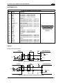
Inputs
All inputs are optocoupled.
SC6000
PWO
Vext
USER INTERFACE
V
Signal
A/B
+ 5V
+
PSIN
~
~
B/A
Ground
Figure 42 – PNP Command Input with Electrical Isolation
SC6000
PWO
A/B
+ 5V
PSIN
+
~
~
Vext
USER INTERFACE
V
B/A
Signal
Ground
Figure 43 - NPN Command Input with Electrical Isolation
41
SC6000
A
SC6000
PWO
USER INTERFACE
V
VS_INPUTS
Signal
A/B
B/A
Ground
GND
Figure 44 - PNP Command Input Using System Power
SC6000
PWO
VS_INPUTS
USER INTERFACE
V
A/B
B/A
Signal
GND
Ground
Figure 45 - NPN Command Input Using System Power
Isolation between the command logic and the scanner is maintained by powering the inputs
with an external supply voltage (Vext). For convenience, the inputs can be powered using the
VS_INPUTS signal on the SC6000 (pin 9). In this case, however, the device is no longer
electrically isolated. The VS_INPUTS signal on the Extended I/O connector is short-circuit
protected.
The electrical features of these inputs are:
Maximum voltage 30 V
Maximum current 10 mA
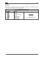
Outputs
Six general purpose outputs are available.
Pin
6
19
7
20
8
21
10
23
11
24
12
25
Name
OUT 1+
OUT 1OUT 2+
OUT 2OUT 3+
OUT 3OUT 4+
OUT 4OUT 5+
OUT 5OUT 6+
OUT 6-
Function
Configurable digital output 1 – positive pin
Configurable digital output 1 – negative pin
Configurable digital output 2 – positive pin
Configurable digital output 2 – negative pin
Configurable digital output 3 – positive pin
Configurable digital output 3 – negative pin
Configurable digital output 4 – positive pin
Configurable digital output 4 – negative pin
Configurable digital output 5 – positive pin
Configurable digital output 5 – negative pin
Configurable digital output 6 – positive pin
Configurable digital output 6 – negative pin
The function of all six outputs can be defined by the user.
Refer to Genius™ Help On-Line for further details.
42
ALTERNATIVE CONNECTIONS REFERENCE
A
By default, OUT1 is associated with COMPLETE READ event, which activates when the code
has been read correctly. In case the reader has been programmed to read several codes
within the same reading phase, the event activates when all codes have been read.
OUT2 is associated with NO READ event, which activates when no code has been read.
OUT3 - OUT6 are associated with NONE, which means that the output is always in line state.
Isolation between the command logic and the SC6000 is maintained by powering the outputs
with an external supply voltage (Vext). For convenience, the outputs can be powered using
the VS_OUTPUTS signal on the SC6000 (pin 1). In this case, however, the device is no
longer electrically isolated. The VS_OUTPUTS on the Extended I/O connector is short-circuit
protected.
The electrical features of these outputs are:
Collector-emitter voltage
Collector current
Saturation voltage (VCE)
Maximum power dissipation
30 V Max.
130 mA Max.
1 V at 10 mA Max.
90 mW at 50°C (Ambient temperature).
The limit requested by the maximum power dissipation is more important than that of the
maximum collector current: if one of these outputs is continuously driven, the maximum
current must not be more than 40 mA although 130 mA may be reached in pulse conditions.
SC6000
PWO
Vext
USER INTERFACE
V
+
C
Signal
-
Ground
E
Figure 46 - Open Collector Output Connection with Electrical Isolation
SC6000
PWO
VS_OUTPUTS
USER INTERFACE
V
+
-
Signal
GND
Ground
Figure 47 - Open Collector Output Connection Using System Power
43
SC6000
A
MODEM
SC6000 offers a dedicated 9-pin port for a Modem connection. The modem connection
allows a Host to remotely control the reading station.
9-pin D-sub Male Connector Pinout
Pin
1
2
3
4
5
6
7
8
9
44
Name
CD
RX
TX
DTR
GND
DSR
RTS
CTS
RI
Function
Carrier detect
Receive
Transmit
Data terminal ready
Ground
Data set ready
Request to send
Clear to send
Ring indicator
5
1
6
9
9-pin D-sub Male Connector
GLOSSARY
Barcode
A pattern of variable-width bars and spaces which represents numeric or alphanumeric data
in machine-readable form. The general format of a barcode symbol consists of a leading
margin, start character, data or message character, check character (if any), stop character,
and trailing margin. Within this framework, each recognizable symbology uses its own unique
format.
Barcode Label
A label that carries a barcode and can be affixed to an article.
Baud Rate
A unit used to measure communications speed or data transfer rate.
EEPROM
Electrically Erasable Programmable Read-Only Memory. An on-board non-volatile memory
chip.
Full Duplex
Simultaneous, two-way, independent transmission in both directions.
Host
A computer that serves other terminals in a network, providing services such as network
control, database access, special programs, supervisory programs, or programming
languages.
Interface
A shared boundary defined by common physical interconnection characteristics, signal
characteristics and meanings of interchanged signals.
LED (Light Emitting Diode)
A low power electronic device that can serve as a visible or near infrared light source when
voltage is applied continuously or in pulses. It is commonly used as an indicator light and
uses less power than an incandescent light bulb but more than a Liquid Crystal Display
(LCD). LEDs have extremely long lifetimes when properly operated.
Parameter
A value that you specify to a program. Typically parameters are set to configure a device to
have particular operating characteristics.
Protocol
A formal set of conventions governing the formatting and relative timing of message
exchange between two communicating systems.
RS232
Interface between data terminal equipment and data communication equipment employing
serial binary data interchange.
RS485
Interface that specifies the electrical characteristics of generators and receivers for use in
balanced digital multipoint systems such as on a Multidrop line.
45
Scanner
A device that examines a printed pattern (barcode) and either passes the uninterpreted data
to a decoder or decodes the data and passes it onto the Host system.
Serial Port
An I/O port used to connect a scanner to your computer, identifiable by a 9-pin or 25-pin
connector.
Signal
An impulse or fluctuating electrical quantity (i.e.: a voltage or current) the variations of which
represent changes in information.
Symbol
A combination of characters including start/stop and checksum characters, as required, that
form a complete scannable barcode.
Trigger Signal
A signal, typically provided by a photoelectric sensor or proximity switch, which informs the
scanner of the presence of an object within its reading zone.
46
INDEX
A
Accessories; 3
C
Connector Pinouts; 36
Connectors
DeviceNet; 11
Ethernet; 9
Profibus; 12
D
DARPTM; 31
DeviceNet; 11
E
Electrical Connections; 8
G
General View; vii
Genius™ Installation; 17
Glossary; 45
Guide to Installation; ix
Guide to Rapid Configuration for DS6000,
DS8100A and DX8200A Slave
Scanners; 17
Guide to Rapid Configuration for DS8100
and DX8200 Slave Scanners; 23
I
Inputs; 41
Installation; 4
Interfaces
Auxiliary; 8
Ethernet; 10
Main RS232; 39
Main RS485 Full Duplex; 40
Profibus; 12
K
Keypad and Display; 15
L
LED Indicators; 2
Lonworks; 37
M
Mechanical Mounting; 6
Model Description; 1
Modem; 44
N
Network Setup; 19
O
Outputs; 42
Overall Dimensions; 5
P
Package Contents; 4
Parameter Default Values; 27
Power Supply; vi
Power/Net Connector; 36
Profibus; 12
PS/PS AUX/Encoder; 37
R
Reference Documentation; v
S
Safety Regulations; vi
Services and Support; v
Software Configuration; 17
T
Technical Features; 35
Troubleshooting; 33
Typical Layouts; 13
W
WEEE Compliance; vi
47
DATALOGIC S.p.A.,
Via Candini, 2
40012 - Lippo di Calderara
Bologna - Italy
05
dichiara che
declares that the
déclare que le
bescheinigt, daß das Gerät
declare que el
e tutti i suoi modelli
and all its models
et tous ses modèles
und seine modelle
y todos sus modelos
SC6000-XXXX, Universal Controller
SC6000-XXXX
sono conformi alle Direttive del Consiglio Europeo sottoelencate:
are in conformity with the requirements of the European Council Directives listed below:
sont conformes aux spécifications des Directives de l'Union Européenne ci-dessous:
der nachstehend angeführten Direktiven des Europäischen Rats:
cumple con los requisitos de las Directivas del Consejo Europeo, según la lista siguiente:
89/336/EEC EMC Directive
e
and
et
und
y
92/31/EEC, 93/68/EEC
emendamenti successivi
further amendments
ses successifs amendements
späteren Abänderungen
succesivas enmiendas
Basate sulle legislazioni degli Stati membri in relazione alla compatibilità elettromagnetica ed alla sicurezza dei
prodotti.
On the approximation of the laws of Member States relating to electromagnetic compatibility and product safety.
Basées sur la législation des Etats membres relative à la compatibilité électromagnétique et à la sécurité des
produits.
Über die Annäherung der Gesetze der Mitgliedsstaaten in bezug auf elektromagnetische Verträglichkeit und
Produktsicherheit entsprechen.
Basado en la aproximación de las leyes de los Países Miembros respecto a la compatibilidad electromagnética y
las Medidas de seguridad relativas al producto.
Questa dichiarazione è basata sulla conformità dei prodotti alle norme seguenti:
This declaration is based upon compliance of the products to the following standards:
Cette déclaration repose sur la conformité des produits aux normes suivantes:
Diese Erklärung basiert darauf, daß das Produkt den folgenden Normen entspricht:
Esta declaración se basa en el cumplimiento de los productos con la siguientes normas:
EN 55022 (Class A ITE), August 1994:
Amendment A1 (Class A ITE), October 2000:
LIMITS AND METHODS OF MEASUREMENTS OF RADIO DISTURBANCE
CHARACTERISTICS OF INFORMATION TECHNOLOGY EQUIPMENT
EN 61000-6-2, October 2001:
ELECTROMAGNETIC COMPATIBILITY (EMC)
PART 6-2: GENERIC STANDARDS - IMMUNITY
FOR INDUSTRIAL
ENVIRONMENTS
Lippo di Calderara, 08.09.05
Ruggero Cacioppo
Quality Assurance Laboratory Manager