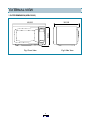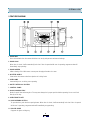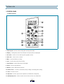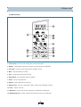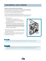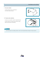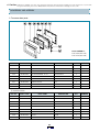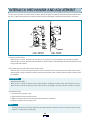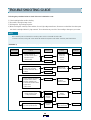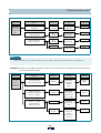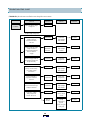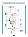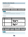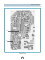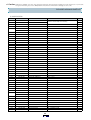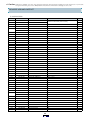
1
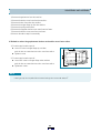
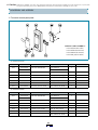
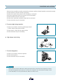
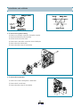
S/M No. : R631G0P001
Service Manual
Microwave Oven
Model: KOR-631G0P
KOR-631H0P
KOR-861G0P
KOR-861H0P
✔ Caution
: In this Manual, some parts can be changed for improving, their
performance without notice in the parts list. So, if you need the
latest parts information,please refer to PPL(Parts Price List) in
Service Information Center (http://svc.dwe.co.kr).
DAEWOO ELECTRONICS CO., LTD.
PRECAUTIONS TO BE OBSERVED BEFORE AND
DURING SERVICING TO AVOID POSSIBLE
EXPOSURE TO EXCESSIVE MICROWAVE ENERGY
(a) Do not operate or allow the oven to be operated with the door open.
(b) M ake the following safety checks on all ovens to be serviced before activating the m agnetron or other m icrowave
source, and m ake repairs as necessary: (1) Interlock operation, (2) Proper door closing, (3) Seal and sealing
surfaces (arcing, wear, and other dam age), (4) Dam age to or loosening of hinges and latches, (5) E vidence of
dropping or abuse.
(c) Before turning on power to the m icrow ave oven for any service test or inspection within the m icrowave
generating com partm ents, check the m agnetron, wave guide or transm ission line, and cavity for proper
alignm ent, integrity, and connections.
(d) Any defective or m isadjusted com ponents in the interlock, m onitor, door seal, and m icrowave generation and
transm ission system s shall be repaired, replaced, or adjusted by procedures described in this m anual before the
oven is released to the owner.
(e) A m icrowave leakage check to verify com pliance with the Federal perform ance standard should be perform ed on
each oven prior to release to the owner.
SAFETY AND PRECAUTIONS ........................................................................................................... 2
1. FOR SAFE OPERATION .............................................................................................................. 2
2. FOR SAFE SERVICE PROCEDURES ......................................................................................... 2
SPECIFICATIONS ............................................................................................................................... 3
EXTERNAL VIEW................................................................................................................................ 4
1. OUTER DIMENSION .................................................................................................................... 4
2. FEATURE DIAGRAM .................................................................................................................... 5
3. CONTROL PANEL ........................................................................................................................ 6
INSTALLATION ................................................................................................................................... 8
OPERATIONS AND FUNCTIONS....................................................................................................... 9
DISASSEMBLY AND ASSEMBLY...................................................................................................... 10
INTERLOCK MECHANISM AND ADJUSTMENT............................................................................... 17
TROUBLE SHOOTING GUIDE ........................................................................................................... 18
MEASUREMENT AND TEST .............................................................................................................. 22
1. MEASUREMENT OF THE MICROWAVE POWER OUTPUT ...................................................... 22
2. MICROWAVE RADIATION TEST ................................................................................................. 23
3. COMPONENT TEST PROCEDURE ............................................................................................. 24
WIRING DIAGRAM.............................................................................................................................. 25
PRINTED CIRCUIT BOARD................................................................................................................ 26
1. CIRCUIT CHECK PROCEDURE .................................................................................................. 26
2. P.C.B. CIRCUIT DIAGRAM........................................................................................................... 29
3. P.C.B. LOCATION NO .................................................................................................................. 30
EXPLODED VIEW AND PARTS LIST................................................................................................. 32
1. DOOR ASSEMBLY ....................................................................................................................... 32
2. CONTROL PANEL ASSEMBLY.................................................................................................... 32
3. TOTAL ASSEMBLY....................................................................................................................... 32
SAFETY AND PRECAUTIONS
1. FOR SAFE OPERATION
D am age that allow s the m icrow ave energy (that cooks or heats the food) to escape w ill result in poor cooking and m ay cause
serious bodily injury to the operator.
IF A N Y O F TH E FOLLO W IN G CO N D ITIO N S E X IS T, O P E RATO R M U S T N O T US E TH E A P P LIA N C E .
(O nly a trained service personnel should m ake repairs.)
1) A broken door hinge.
2) A broken door view ing screen.
3) A broken front panel, oven cavity.
4) A loosened door lock.
5) A broken door lock.
The door gasket plate and oven cavity surface should be kept clean.
N o grease, soil or spatter should be allow ed to build up on these surfaces or inside the oven.
D O N OT ATTE M PT TO O P E R ATE THIS A P P LIA N CE W ITH TH E D O O R O P EN . The m icrow ave oven has concealed sw itches
to m ake sure the power is turned off w hen the door is opened. D o not attem pt to defeat them .
D O N OT ATTE M PT TO S E RV IC E TH IS A P P LIA N C E U N TIL Y O U H AVE R E A D THIS S E RV IC E M A NU A L.
2. FOR SAFE SERVICE PROCEDURES
1) If the oven is operative prior to servicing, a m icrowave em ission check should be perform ed prior to servicing the oven.
2) If any certified oven unit is found to servicing, a m icrowave em ission check should be perform ed prior to servicing the oven.
(a) inform the m anufacturer, im porter or assem bler,
(b) repair the unit at no cost to the ow ner,
(c) attem pt to ascertain the cause of the excessive leakage,
(d) tell the ow ner of the unit not to use the unit until the oven has been brought into com pliance.
3) If the oven operates with the door open, the service person should tell the user not to operate the oven and contact the
m anufacturer im m ediately.
IMPORTANT
The w ire in this m ains lead coloured in accordance w ith the follow ing code.
G reen-and-yellow : E arth
B lue
: N eutral
B row n
: Live
A s the colours of the w ires in the m anins lead of this appliance m ay not correspond w ith the coloured m arkings
identifying the term inals in your plug, proceed as follow s.
The w ire w hich is coloured green-and-yellow m ust be connected to the term ianl in the plug w hich is m arked with the
letter ‘E ’, earth sym bol or coloured green-and-yellow.
The w ire w hich is coloured blue m ust be connected to the term inal which is m arked w ith the letter ‘N ’ or
coloured black.
The w ire w hich is coloured brow n m ust be connected to the term inal w hich is m arked w ith the letter ‘L’ or
coloured red.
NOTE
This oven is designed for counter-top use only.
SPECIFICATIONS
M O D EL
KO R -631G /H
PO W E R SU P PLY
220V -60H z, SIN G LE PH AS E W ITH E AR TH IN G
M IC R O W AVE
PO W E R
C O N SU M PTIO N
KO R -861G /H
1200W
1300W
800W
900W
G R ILL
C O M BIN ATIO N
M IC R O W AVE E N E R G Y O U TP U T
M IC R O W AVE F R E Q U E N C Y
2450M H z
O U T S ID E D IM EN SIO N S (W X H X D )
465 x 279 x 360m m (18.3 x 11.0 x 14.2 in.)
495 x 294 x 388m m (19.5 x 11.6 x 15.3 in.)
C AV IT Y D IM E N S IO N S (W X H X D )
290 x 220 x 306 m m (11.4 x 8.7 x 12.0 in.)
320 x 244 x 338m m (12.6 x 9.6 x 13.3 in.)
N E T W E IG H T
A PP R O X . 13Kg ( 28.7lbs.)
AP PR O X. 15Kg ( 33.1lbs.)
TIM ER
59 m in. 90 sec.
FU N C T IO N S ELE C T IO N S
M IC R O W AV E
PO W E R SE LE C T IO N S
C AV IT Y VO LU M E
10 LE VE LS
0.7 C u.Ft.
SPECIFICATIONS ARE SUBJECT TO CHANGE W ITHOUT NOTICE.
0.9 C u.Ft.
EXTERNAL VIEW
1. OUTER DIMENSION (KOR-631/861)
465/495
279/294
360/388
Fig.2 Side View
Fig.1 Front View
EXTERNAL VIEW
2. FEATURE DIAGRAM
1. DOOR SEAL
Door seal m aintains the m icrowave within the oven cavity and prevents m icrowave leakage.
2. DOOR HOOK
W hen door is closed, it will autom atically lock shut. If door is opened while oven is operating, m agnetron tube will
im m ediately stop operating.
3. DOOR SCREEN
Allows viewing of food. M icrowave cannot pass through perforations in screen.
4. SPATTER SHIELD
Protects the m icrowave outlet from splashes of cooking foods.
5. OVEN LAMP
Autom atically turns on during oven operating.
6. SAFETY INTERLOCK SYSTEM
7. CONTROL PANEL
8. GLASS COOKING TRAY
M ade of special heat resistant glass. The tray m ust always be in proper position before operating. Do not cook food
directly on the tray..
9. OVEN FRONT PLATE
10. DOOR OPENING BUTTON
To open the door, push the door opening button. W hen door is closed, it will autom atically lock shut. If door is opened
while oven is operating, m agnetron tube will im m ediately stop operating.
11. ROLLER GUIDE
Supports the glass cooking tray.
EXTERNAL VIEW
3. CONTROL PANEL
(1) KOR-631G/861G
1. Time set pad - Used to set the cooking tim e and the present tim e.
2. Display - Cooking tim e, power level, indicators and present tim e are displayed.
3. One touch - Used to cook or reheat specific quantities of food.
4. Auto cook - Used to cook or reheat.
5. More - Used to add tim e to cooking.
6. Less - Used to rem ove tim e from cooking.
7. Auto Defrost - Used to defrost foods.(for weight)
8. Power - Used to set power level.
9. Defrost - Used to defrost foods.(for tim e)
10. Kitchen Tim er - Used as a m inute tim er, delay cooking, hold setting after cooking.
11. Clock - Used to set clock.
12. Stop/Clear - Used to stop the oven operation or to delete the cooking data.
13. Start/Speedy cook - Used to start the oven and also used to set a reheat tim e.
EXTERNAL VIEW
(2) KOR-631H/861H
1. Time set pad - Used to set the cooking tim e and the present tim e.
2. Display - Cooking tim e, power level, indicators and present tim e are displayed.
3. One touch - Used to cook or reheat specific quantities of food.
4. More - Used to add tim e to cooking.
5. Less - Used to rem ove tim e from cooking.
6. Auto Defrost - Used to defrost foods.(for weight)
7. Power - Used to set power level.
8. Defrost - Used to defrost foods.(for tim e)
9. Kitchen Timer - Used as a m inute tim er, delay cooking, hold setting after cooking.
10. Clock - Used to set clock.
11. Stop/Clear - Used to stop the oven operation or to delete the cooking data.
12. Start/Speedy cook - Used to start the oven and also used to set a reheat tim e.
INSTALLATION
1. Steady, flat location
This m icrow ave oven should be set on a steady, flat surface.
This m icrow ave oven is designed for counter top use only.
2. Leave space behind and side
A ll air vents should be kept a clearance. If all vents are covered during operation, the oven m ay overheat and, eventually,
cause failure.
3. A w ay from radio and TV sets
Poor television reception and radio interference m ay result if the oven is located close to a TV, radio, antenna or feeder and so on.
Position the oven as far from them as possible.
4. A w ay from heating appliances and w ater taps
K eep the oven aw ay from hot air, steam or splash w hen choosing a place to position it, or the insulation m ight be adversely
affected and breakdow ns occur.
5. Power supply
C heck your local pow er source.
This m icrow ave oven requires a current of approxim ately 6 am peres, 220 Volts, 60 H z.
P ow er supply cord is about 0.8 m eters long.
The voltage used m ust be the sam e as specified on this oven. U sing a higher voltage m ay result in a fire or other accident
causing oven dam age. U sing low voltage will cause slow cooking. W e are not responsible for dam age resulting from use
of this oven w ith a voltage of am pere fuse other than those specified.
This appliance is supplied w ith cable of special type, w hich, if dam aged, m ust be repaired w ith cable of sam e type.
S uch a cable can be purchased from DA E W O O and m ust be installed by a Q ualified P erson.
6. Examine the oven after unpacking for any dam age such as:
A m isaligned door, broken door or a dent in cavity.
If any of the above are visible, D O N OT IN S TA LL, and notify dealer im m ediately.
7. D o not operate the oven if it is colder than room temperature
(This m ay occur during delivery in cold w eather.) Allow the oven to becom e room tem perature before operating.
EARTHING INSTRUCTIONS
This appliance m ust be earthed. In the event of an electrical short circuit, earthing reduces the risk of the electric shock by
providing an escape w ire for the electric current. This appliance is equipped with a cord having a earthing wire with a earthing
plug. The plug m ust be plugged into an outlet that is properly installed and earthed.
WARNING
Im proper use of the earthing plug can result in a risk of electric shock. C onsult a qualified electrician or servicem an if
the earthing instructions are not com pletely understood, or if doubt exists as to w hether the appliance is properly
earthed, and either : If it is necessary to use an extension cord, use only a 3-wire extension cord that has a 3-blade
earthing plug, and a 3-slot receptacle that w ill accept the plug on the appliance. The m arked rating of the extension
cord should be equal to or greater than the electrical rating of the appliance, or D o not use an extension cord.
OPERATIONS AND FUNCTIONS
1. Connect the m ain lead to an electrical outlet.
2. After placing the food in a suitable container, open the oven door and put it on the glass tray. The glass tray m ust always
be in place during cooking.
3. Close the door securely.
4. W hen the oven door is opened, the light turns off.
5. The oven door can be opened at any tim e during operation by touching the door release button on the control panel.
The oven will autom atically shut off. To restart the oven, close the door and then touch START.
6. Each tim e a pad is touched, a BEEP will sound to acknowledge the touch.
7. The oven autom atically cook on full power unless set to a lower power level.
8. The display will show :0 when the oven is plugged in.
9. Tim e clock returns to the present tim e when the cooking tim e ends.
10. W hen the STOP /CLEAR pad is touched during the oven operation, the oven stops cooking and all inform ation retained.
To erase all inform ation (except the present tim e), touch the STOP/CLEAR pad once m ore. If the oven door is opened
during the oven operation, all inform ation is retained.
11. If the START pad is touched and the oven does not operate, check the area betw een the door and door is closed
securely. The oven will not start cooking under the door is com pletely closed or the program has been reset.
M ake sure the oven is properly installed and plugged into the electrical outlet.
W attage output chart
The power level is set by pressing the Power pad. The chart shows the display, the power level and the percentage of
power.
Touch Power pad.
Pow er level (Display)
Approximate Percentage of Pow er
O nce
P -H I
100 %
Tw ice
P -90
90 %
3 tim es
P -80
80 %
4 tim es
P -70
70 %
5 tim es
P -60
60 %
6 tim es
P -50
50 %
7 tim es
P -40
40 %
8 tim es
P -30
30 %
9 tim es
P -20
20 %
10 tim es
P -10
10 %
11 tim es
P -00
0%
DISASSEMBLY AND ASSEMBLY
Cautions to be observed when trouble shooting
Unlike many other appliances, the microwave oven is high-voltage, high-current equipment.
It is completely safety during normal operation. However, carelessness in servicing the oven
can result in an electric shock or possible danger from a short circuit.
You are asked to observe the following precautions carefully.
1. Always remove the power plug from the outlet before servicing.
2. Use an insulated screwdriver and ware rubber gloves when servicing the high voltage side.
3. Discharge the high voltage capacitor before touching any oven components or wiring.
(1) Check the earthed.
Do not operate on a two-wire extension cord.
The microwave oven is designed to be used with earthed.
It is imperative, therefore, to makes sure it is earthed properly
before beginning repair work.
(2) Warning about the electric charge in the high voltage capacitor.
For about 30 seconds after the operation stopped and electric
charge remains in the high voltage capacitor. When replacing
or checking parts, short between oven chassis and the negative
high terminal of the high voltage capacitor, by using a properly
insulated screwdriver to discharge.
4. When the 12A fuse is blown out due to the operation of the monitor
switch; replace primary interlock switch, secondary interlock switch
and interlock monitor switch.
5. After repair or replacement of parts, make sure that the screws are
properly tightened, and all electrical connections are tightened.
6. Do not operate without cabinet.
CAUTION
S ervice personnel should rem ove their w atches w henever working close to or replacing the m agnetron.
WARNING
W hen servicing the appliance, need a care of touching or replacing high potential parts because of electrical shock or
exposing m icrow ave. These parts are as follow s - H V Transform er, M agnetron, H V C apacitor, HV D iode.
DISASSEMBLY AND ASSEMBLY
1. To rem ove cabinet
1) Rem ove three screws on cabinet back.
2) Push the cabinet backward.
.2. To rem ove door assem bly
1) Rem ove a screw which secure the stopper hinge top.
2) Rem ove the door assem bly from top plate of cavity.
3) Reverse the above for reassem bly.
NOTE
A fter replacing the door assem bly, perform a check of correct alignm ent with the hinge and cavity front plate.
✔ Caution: In this Service Manual, some parts can be changed for improving, their performance without notice in the parts list. So, if you need the
latest parts information, please refer to PPL(Parts Price List) in Service information Center(http://svc.dwe.co.kr)
DISASSEMBLY AND ASSEMBLY
3. To rem ove door parts.
DO OR A SSEMB LY :
3511710300(K O R-631)
3511710700(K O R-861)
(1) KOR-631G/631H
REF. NO
PA RT CODE
PART N AME
DESCRIPTION
Q TY
A 01
3512203800
FR A M E D O O R
A BS X R -401 H -2938
1
A 02
3517003050
BA R R IER -S C RE E N *O
A CRY L
1
A 03
3515304610
SU P P O RTE R B AR R -S *O
PP
1
A 04
3515204100
ST OP P E R H IN G E *T A S
K O R -63150S
1
A 05
3511705500
DO O R W E LD A S
K O R -61150S
1
A 06
3517002800
BA R R IER -S C RE E N *I
P O LY E S T ER T 0.1
1
A 07
3512300200
GA S K E T D O O R
PP
1
A 08
3513100700
HO O K
POM
1
A 09
3515101300
SP R IN G H O O K
PW1
1
REMARK
(2) KOR-861G/861H
REF. NO
PA RT CODE
PART N AME
DESCRIPTION
A 01
3512204100
FR A M E D O O R
A BS X R -401 H -2938
1
A 02
3517003150
BA R R IER -S C RE E N *O
A CRY L
1
A 03
3515304410
SU P P O RTE R B AR R -S *O
PP
1
A 04
3515204100
ST OP P E R H IN G E *T A S
K O R -63150S
1
A 05
3511705620
DO O R W E LD A S
K O R -81250S
1
A 06
3517002900
BA R R IER -S C RE E N *I
P O LY E S T ER T 0.1
1
A 07
3512300400
GA S K E T D O O R
PP
1
A 08
3513100700
HO O K
POM
1
A 09
3515101300
SP R IN G H O O K
PW1
1
Q TY
REMARK
DISASSEMBLY AND ASSEMBLY
1) Rem ove
2) Rem ove
3) Rem ove
4) Rem ove
5) Rem ove
6) Rem ove
7) Rem ove
8) Reverse
the gasket door from door weld as.
the barrier screen inner from door weld as.
the door fram e from door weld as.
the stopper hinge top from door weld as.
the spring and the hook.
the supporter barrier screen outer from door fram e.
the barrier screen outer from door fram e.
the above steps for reassem bly.
4. M ethod to reduce the gap betw een the door seal and the oven front surface.
1) To reduce gap located on part ‘A’.
Loosen a screw on stopper hinge top, and then
push the door to contact the door seal to oven front surface.
Tighten a screw.
2) To reduce gap located on part ‘B’.
Loosen two screws on stopper hinge under, and then
push the door to contact the door seal to oven front surface.
Tighten two screws.
NOTE
A sm all gap m ay be acceptable if the m icrow ave leakage does not exceed 4m W /cm 2 .
✔ Caution: In this Service Manual, some parts can be changed for improving, their performance without notice in the parts list. So, if you need the
latest parts information, please refer to PPL(Parts Price List) in Service information Center(http://svc.dwe.co.kr)
DISASSEMBLY AND ASSEMBLY
5. To rem ove control panel parts.
C ON TRO L PA NEL ASSEM BLY :
P KC P SW ZH00(KO R -631G)
P KC P SW ZM 00(KO R-631H)
P KC P SW N K00(KO R -861G)
P KC P SW N J00(KO R -861H)
(1) KOR-631G/631H
REF.NO
PART CODE
B 01
3518520900
PART NAM E
DES CRIPTION
K O R -631 G 0 S
S W ITC H M E M B R AN E
3518520910
B 02
3516719000
B 03
P KM P M SZ A 00
B 04
QTY
REM ARK
1
K O R -631H 0S
C O NT R O L-PAN E L
A BS X R -401 H -2938
1
P C B M A IN AS
K O R -631 H 0S
1
7122401211
S C R EW TA P PIN G
T2S TR S 4X12 M FZN
4
B 05
3513702700
LE V ER D O O R O P EN
A BS X R -401 H -2938
1
B 06
441G 430171
S P R IN G B UT TO N
SW P DIA0.7
1
B 07
3516906900
B U T TO N D O O R O PE N
ABS XR-401 H -2938
1
(2) KOR-861G/861H
REF.NO
PART CODE
B 01
3518521220
PART NAM E
DES CRIPTION
K O R -861 G 0 S
S W ITC H M E M B R AN E
3518521230
B 02
3516720200
B 03
P KM P M SN E 00
B 04
QTY
1
K O R -861H 0S
C O NT R O L-PAN E L
A BS X R -401 H -2938
1
P C B M A IN AS
K O R -860A 0S
1
7122401211
S C R EW TA P PIN G
T2S TR S 4X12 M FZN
4
B 05
3513702700
LE V ER D O O R O P EN
A BS X R -401 H -2938
1
B 06
441G 430171
S P R IN G B UT TO N
SW P DIA0.7
1
B 07
3516906900
B U T TO N D O O R O PE N
ABS XR-401 H -2938
1
REM ARK
DISASSEMBLY AND ASSEMBLY
1) Remove the screw which secure the control panel, push up two snap fits and draw forward the control panel assem bly.
2) Rem ove the door open lever from the control panel.
3) Rem ove four screws which secure the PCB assem bly to control panel.
4) Disconnect m em brane tail from the connector of the PCB assem bly.
5) Detach m em brane from the control panel.
6) Rem ove door open button and button spring from the control panel.
7) Reverse the above steps for reassem bly.
6. To rem ove high voltage capacitor.
1) Rem ove a screw which secure the grounding ring term inal
of the H.V.diode and the capacitor holder.
2) Rem ove the H.V. diode from the capacitor holder.
3) Reverse the above steps for reassem bly.
H igh voltage circuit w iring
7. To rem ove m agnetron.
1) Rem ove a screw which secure the m agnetron.
2) Rem ove the m agnetron.
3) Reverse the above steps for reassem bly.
NOTE
N ever install the m agnetron w ithout the m etallic gasket plate w hich is packed w ith each m agnetron to prevent
m icrow ave leakage. W henever repair w ork is carried out on m agnetron, check the m icrow ave leakage. It shall
not exceed 4m W /cm 2 for a fully assem bled oven with door norm ally closed.
DISASSEMBLY AND ASSEMBLY
8. To remove wind guide assembly.
1) Rem ove a screw which secure the wind guide assem bly.
2) Draw forward the wind guide assem bly.
3) Pull the fan from the m otor shaft.
4) Rem ove two screws which secure the m otor shaded pole.
5) Rem ove the m otor shaded pole.
6) Reverse the above steps for reassem bly.
9. To remove H.V.transformer.
1) Rem ove four screws holding the H.V.transform er.
2) Rem ove the H.V.transform er.
3) Reverse the above steps for reassem bly.
INTERLOCK MECHANISM AND ADJUSTMENT
The door lock m echanism is a device which has been specially designed to com pletely elim inate m icrowave radiation when
the door is opened during operation, and thus to perfectly prevent the danger resulting from the leakage of microwave.
(1) Prim ary interlock switch
W hen the door is closed, the hook locks the oven door. If the door is not closed properly, the oven will not operate.
W hen the door is closed, the hook pushes the button of the m icroswitch. Then the button of the primary interlock switch
bring it under ON condition.
(2) Secondary interlock switch and interlock m onitor switch
W hen the door is closed, the hook pushes the lock lever downward. The lock lever presses the button of the interlock
m onitor switch to bring it under NO condition and presses the button of the secondary interlock switch to bring it under
ON condition.
ADJUSTMENT
Interlock m onitor switch
W hen the door is closed, the interlock m onitor switch should be changed(N O condition) before other sw itches are closed.
W hen the door is opened, the interlock m onitor switch should be changed(N C condition) after other sw itches are opened.
(3) Adjustm ent steps
a) Loosen the one m ounting screw.
b) Adjust interlock switch assem bly position.
c) M ake sure that lock lever m oves sm oothly after adjustm ent is com pleted.
d) Tighten com pletely one m ounting screw.
NOTE
M icrow ave em ission test should be perform ed after adjusting interlock m echanism . If the m icrow ave em ission exceed
4m W /cm 2 , readjust interlock m echanism .
TROUBLE SHOOTING GUIDE
Following the procedure below to check if the oven is defective or not.
1) Check earthing before trouble checking.
2) Be careful of the high voltage circuit.
3) Discharge the high voltage capacitor.
4) W hen checking the continuity of the switches, fuse or high voltage transform er, disconnect one lead wire from these parts
and check continuity with the AC plug removed. To do otherwise m ay result in a false reading or dam age to your meter.
NOTE
W hen electric parts are checked, be sure the pow er cord is not inserted the w all outlet.
C heck w ire harness, w iring and connected of the term inals and power cord before check the parts listed below.
(TROUBLE 1) Oven does not operate at all : any inputs can not be accepted.
C O N D ITIO N
CHECK
Fuse blow s.
C heck co ntinuity of
interlock m onitor sw itch
w ith door closed
(C O M
N C)
C heck co ntinuity of both
prim ary and secondary
interlock sw itch w ith door
colosed
RESULT
C ontinuity
CAUSE
REM EDY
M alfunction
of interlock
m on itor
sw itch
R eplace
N O TE 1
M alfunction of
interlock sw itch
R eplace
N O TE 1
N o C ontinuity
N o C ontinuity
C ontinuity
C heck co ntinuity of prim ary
interlock sw itch contact
w ith door partially open
until interlock m onitor switch
contact close
(C O M <->N O )
C ontinuity
S horted contacts
of prim a ry
interlock sw itch.
R eplace
N O TE 1
C heck co ntinuity of
prim ary w inding of low
voltage transform er
0 Ω or infinite
D efective low
voltage
transform er
R eplace
D efective high
voltage transform er
R eplace
D isconne ct high voltage
fuse and operate the unit
A pprox.
150~310
(norm al)
Fuse again
blows
TROUBLE SHOOTING GUIDE
CON DITION
CHECK
RESULT
CAUSE
REM EDY
O utlet has
proper voltage
Fuse does not
blow.
C heck con tinuity of
m agn etron
No
C ontinuity
D efective
m agn etron
R eplace
C heck con tinuity of
noise filter board
No
C ontinuity
D efective line
filter board
R eplace
C heck con tinuity of
pow er supply cord
No
C ontinuity
O pen pow er
supply cord
R eplace
N orm al
D efective touch
control circuit
A djust
NOTE
A ll these sw itches m ust be replaced at the sam e tim e, please refer to “Interlock M echanism A nd A djustm ent”.
( TROUBLE 2 ) Display shows all figures selected, but oven does not start cooking, even though desired program and tim e
are set and start pad is tapped.
CON DITION
CHECK
RESULT
CAUSE
REM EDY
Turn table
m oto r and
oven lam p do
not turn on
C heck con tinuity of
prim ary interlock sw itch
No
C ontinuity
M alfunction
of prim ary
interlock
sw itch
A djust or
replace
C heck con tinuity of
secondary interlock and
D .O .M . sw itches
No
C ontinuity
M alfunction
of secondary
interlock and
D .O .M . sw itch
A djust or
replace
C heck D .C. voltage
being supplied to
R ELAY (R Y2) coil
0V
D efective
touch control
circuit
R eplace
A pprox.
15 VD C
Faulty
contacts of
R ELAY
(RY 2) or open
relay coil
R eplace
TROUBLE SHOOTING GUIDE
( TROUBLE 3 ) No m icrowave oscillation even though fan m otor rotates.
C ON DITIO N
C HE C K
R ES U LT
N o m icrow ave
oscillation
C heck continuity of high
voltage fu se
N o C ontinuity
C AU S E
R EM ED Y
R epla ce high voltage fuse
C heck continuity of high
voltage capacito r
te rm inals w ith w ires
rem oved
C ontinuity
D efective
high voltage
transform er
R eplace
C heck continuity of high
voltage rectifier in
fo rw ard and backw ard
direction w ith D C
m egge r
C ontinuity in
backw ard
direction
D efective
high voltage
rectifier
R eplace
C onnect m egger leads to
m agne tron term ina l and
m agne tron body
C ontinuity
D efective
m agnetron
R eplace
D efective
high voltage
transform er
R eplace
C heck resistance of
prim ary and secondary
coil of high voltage
transfo rm er
0 Ω or
C heck continuity of
m agne tron w ith w ires
rem oved
No
C ontinuity
D efective
m agnetron
R eplace
C heck continuity of
filam ent term inal of high
voltage transform er
No
C ontinuity
D efective
high voltage
transform er
R eplace
C heck D .C . voltage
being sup plied to
R ELAY (R Y1) coil
0V
D efective
touch control
circuit
R eplace
A pprox
15 V D C
Faulty
contacts or
R ELAY
(RY 1) or open
relay coil
R eplace
TROUBLE SHOOTING GUIDE
( TROUBLE 4 ) The following visual conditions indicate a probable defective touch control circuit or m em brane switch
assem bly
1. Incom plete segm ents,
1) Segm ents m issing.
2) Partical segm ents m issing.
3) Digit flickering other than norm al display slight flickering.
4) “ : 0 ” does not display when power is on.
2. A distinct change in the diplay are not on when they
num bers is the display.
3. One or m ore digits in the diplay are not on when they should be.
4. Display indicates a num ber different from one touched.
5. Specific num bers (for exam ple 2 or 3) will not display when the panel is touched.
6. Display does not count down or up with tim e cooking or clock operation.
7. Oven is program m able and cooks norm ally but no display shows.
8. Display obviously jum ps in tim e while counting down.
9. Display counts down noticeably too fast while cooking.
10. Display does not show the tim e of day when clear pad is touched.
11. Oven lam p and turntable m otor do not stop although cooking is finished. Check if the RELAY 2 contacts close if they are
close, replace touch control circuit.
CON DITION
D isplay does
not show
program m ing
at all, even if
keyboard is
touched.
CHECK
RESULT
CAUSE
REM EDY
C heck each pad for
continuity of the
m em brane keyboard
for the follow ing
keyboard check
proce dure
N orm al
M alfunction
of touch
control circuit
of control box
sub-a ssem bly
R eplace
control box
sub-a ssem bly
A bnorm al
M alfunction of
the m em brane
keyboard
R eplace the
m em brane
keyborad
NOTE
B efore following the particular steps listed above in the trouble shooting guide for the m em brane keyborad’s, failure,
please check for the continuity of each wire-harness betw een the m em brane keyboard and P.C.B . assem bly.
MEASUREMENT AND TEST
1. MEASUREMENT OF THE MICROWAVE POWER OUTPUT
M icrowave output power can be checked by indirectly m easuring the tem perature rise of a certain am ount of water exposed
to the m icrowave as directed below.
PROCEDURE
1. M icrowave power output m easurem ent is m ade with the m icrowave oven supplied at rated voltage and operated at its
m axim um m icrowave power setting with a load of 1000 ± 5cc of potable water.
2. The water is contained in a cylindrical borosilicate glass vessel having a m axim um m aterial thickness of 3 m m and an
outside diam eter of approxim ately 190 m m .
3. The oven and the em pty vessel are at am bient tem perature prior to the start of the test. The initial tem perature of the
water is 10 ± 2 ° C (50 ± 3.6 ° F). It is m easured im m ediately before the water is added to the vessel. After addition of
the water to the vessel, the load is im m ediately placed on the center of the shelf, which is in the lowest norm al position.
4. M icrowave power is switched on.
5. Heating tim e should be exactly A seconds.
(Refer to table as following)
Heating tim e is m easured while the
m icrowave generator is operating at
full power. The filam ent heat-up tim e
for m agnetron is not included.
6. The initial and final tem perature of water is selected
so that the m axim um difference between the am bient
and final water tem perature is 5K.
7. The m icrowave power output P in watts is calculated
from the following form ula:
P = 4187 X
T T is difference between initial and ending tem perature.
t is the heating tim e.
The power m easured should be B (Refer to SPECIFICATIONS) W ± 10.0 % .
CAUTION
1. W ater load should be m easured exactly to 1 liters.
2. Input pow er voltage should be exactly specified voltage (R efer to S PE C IFIC ATIO N S ).
3. A m bient tem perature should be 20 ± 2° C (68 ± 3.6 ° F)
Heating time for power output:
A (second)
70
64
60
56
52
49
47
44
42
40
38
B (W )
600
650
700
750
800
850
900
950
1000
1050
1100
MEASUREMENT AND TEST
2. MICROWAVE RADIATION TEST
CAUTION
1. M ake sure to check the m icrowave leakage before and after repair of adjustm ent.
2. Always start m easuring of an unknown field to assure safety for operating personnel from m icrowave energy.
3. Do not place your hands into any suspected m icrowave radiation field unless the safe density level is known.
4. Care should be taken not to place the eyes in direct line with the source of m icrowave energy.
5. Slowly approach the unit under test until the radiom eter reads an appreciable m icrowave leakage from the unit
under the test.
PROCEDURE
1. Prepare M icrowave Energy Survey M eter,
600cc glass beaker, and glass therm om eter
100° C (212° F ).
2. Pour 275cc ± 15cc of tap water initially at 20 ± 5 ° C
(68 ± 9° F) in the 600 cc glass beaker with an inside
diam eter of approx. 95 m m (3.5 in.).
3. Place it at the center of the tray and set it in a cavity.
4. Close the door and operate the oven.
5. M easure the leakage by using M icrowave Energy
Survey M eter with dual ranges, set to 2450M Hz.
1) M easured radiation leakage m ust not exceed the
value prescribed below. Leakage for a fully assem bled
oven with door norm ally closed m ust be less than 4m W /cm 2 .
2) W hen m easuring the leakage, always use the 5 cm (2 in.) space cone with probe. Hold the probe perpendicular to the
cabinet and door. Place the space cone of the probe on the door, cabinet, door seem , door viewing screen, the exhaust
air vents and the suction air vents.
3) M easuring should be in a counter-clockwise direction at a rate of 1 in./sec. If the leakage of the cabinet door seem is
unknown, m ove the probe m ore slowly.
4) W hen m easuring near a corner of the door, keep the probe perpendicular to the areas m aking sure the probe end at
the base of the cone does not get closer than 2 in. from any m etal. If it does not, erroneous reading m ay result.
MEASUREMENT AND TEST
3. COMPONENT TEST PROCEDURE
High voltage is present at the high voltage term inal of the high voltage transform er during any cooking cycle.
It is neither necessary nor advisable to attem pt m easurem ent of the high voltage.
Before touching any oven components or wiring, always unplug the oven from its power source and discharge the capacitor.
1. High voltage transformer
1) Rem ove connections from the transform er term inals and check continuity.
2) Norm al readings should be as follows :
Secondary winding ... Approx. 100
Prim ary winding ... Approx. 1 ± 10%
Filam ent winding ... Approx. 0
2. High voltage capacitor
1) Check continuity of capacitor with m eter on the highest OHM scale.
2) A norm al capacitor will show continuity for a short tim e, and then indicate 10M
3) A shorted capacitor will show continuous continuity.
once the capacitor charged.
4) An open capacitor will show constant 10M .
5) Resistance between each term inal and chassis should be infinite.
3. High voltage diode
1) Isolate the diode from the circuit by disconnecting the leads.
2) W ith the ohm m eter set on the highest resistance scale m easure the resistance across the diode term inals. Reverse
the m eter leads and again observe the resistance reading. M eter with 6V, 9V or higher voltage batteries should be
used to check the front-back resistance of the diode, otherwise an infinite resistance m ay be read in both directions. A
norm al diode's resistance will be infinite in one direction and several hundred k
in the other direction.
4. Magnetron
For com plete m agnetron diagnosis, refer to “M easurem ent of the M icrowave Power Output. " Continuity checks can only
indicate and open filam ent or a shorted m agnetron. To diagnose for an open filam ent or a shorted m agnetron,
1) Isolate m agnetron from the circuit by disconnecting the leads.
2) A continuity check across m agnetron filam ent term inals should indicate 0.1
or less.
3) A continuity check between each filam ent term inal and m agnetron case should read open.
5. Fuse
If the fuse in the prim ary and m onitor switch circuit is blown when the door is opened, check the prim ary and m onitor
switch before replacing the blown fuse. In case the fuse is blown by an im proper switch operation, replace the defective
switch and fuse at the sam e tim e. Replace just the fuse if the switches operate norm ally.
WIRING DIAGRAM
PRINTED CIRCUIT BOARD
1. CIRCUIT CHECK PROCEDURE
1. Low voltage transformer check
The low voltage transform er is located on the P.C.B.
M easuring condition: Input voltage: 220 V / Frequency: 60Hz
Term inal Voltage
LO AD
N O LO A D
4-7
A C 12.6 V
A C 14.7 V
NOTE
1. Refer to Circuit Diagram (point 4).
2. Secondary side voltage of the low voltage transformer changes in proportion to fluctuation of power source voltage.
3. The allowable tolerance of the secondary voltage is within 5% of nom inal voltage.
2. Voltage Check
- Key check point
NO
CHECK POINT
1
IC1 P IN 2,21,30,34
2
IC1 P IN 35
REMARK
-5VD C
T : 16.67m s(60H z)
3
IC1 P IN 31 O R 32
T : 250 ns(4M H z)
- Check m ethod
NO
MEASURE POINT
WAVE FORM
REMEDY
REM ARK
1
MP1
D C -5V ± 0.25V
R eplace V L1, E C 1
N O LO A D
2
MP2
D C -12V ± 2.0V
Replace E C 2, D12,13,14
N O LO A D
NOTE
Each m easure point m ust be m easured with GND points.
PRINTED CIRCUIT BOARD
M P1
M P2
Measure Point
PRINTED CIRCUIT BOARD
3. W hen there is no microwave oscillation
1) W hen touching START pad, oven lam p does not turn on.
Fan m otor do not rotate, but cook indicator in display com es on.
Cause : RELAY 2 does not operate. refer to Circuit Diagram ( Point 3)
- Check m ethod
POINT
A
B
RELA Y 2 O N
- 5V DC
GND
RELA Y 2 O F F
GND
- 12V DC
STATE
2) W hen touching START pad, oven lam p turns on.
Fan m otor and turntable rotate and cook indicator in display com es on.
Cause : RELAY 1 does not operate. refer to Circuit Diagram ( Point 2 )
- Check m ethod
P OINT
A
B
R ELA Y 1 O N
-5VD C
G ND
RELA Y 1 O FF
G ND
-12VD C
STATE
4. W hen the door is opened during operation, the count down timer does not stop.
refer to Circuit Diagram ( Point 1 )
- Check m ethod
PO INT
A
B
1) DO O R O P E N
O P EN
-5V DC
2) D O O R C LO S E D
C LO SE
GND
STATE
CHECK N O
METHOD
REM EDY
1
C heck the stage(O N,O F F) of the door open m onitor switch by resistance
m easurem ent.
Replace door open m onitor sw itch.
5. W hen the digital clock does not operate properly.
refer to Circuit Diagram ( Point 5 )
POINT
A
WAVE FORM
T: 16.67m s(60H z)
If clock does not keep exact tim e, you m ust check resistor R15,16, zener diodeZD1.
PRINTED CIRCUIT BOARD
2. P.C.B. CIRCUIT DIAGRAM
✔ Caution: In this Service Manual, some parts can be changed for improving, their performance without notice in the parts list. So, if you need the
latest parts information, please refer to PPL(Parts Price List) in Service information Center(http://svc.dwe.co.kr)
PRINTED CIRCUIT BOARD
3. P.C.B. LOCATION NO
(1) KOR-631G/631H
NO
NAM E
SYM BOL
SP ECIFIC ATION
PART CODE
Q 'TY
1
B UZ Z E R
B Z1
B M -20K
3515600100
1
2
C AR R AY
CA 1
7P(6) 102 M 50V
CN 6X B-102M
1
3
C APAC ITO R ELE C
E C1
16V R S S 100uF
CE X F 1C 101V
1
4
C APAC ITO R ELE C
E C2
25V R S S 1000uF
C E X F 1E 102V
1
5
C O N N E CT O R W A F E R
CN 1
Y W 396-02AV
3519150520
1
6
C O N N E CT O R W A F E R
CN 2
Y W 396-05AV
3519150510
1
7
C O N N E CT O R W A F E R
CN 3
F CZ 254-11
441M 367160
1
8
D IO D E R EC T IF Y
D1~6,9~12
1N4148
D Z N 4148---
10
9
D IO D E R EC T IF Y
D13,14
1N4002A
D Z N 4002A --
2
10
D IO D E Z EN E R
Z D1
M TZ 5.1VB 1/2W
D Z T Z 5R 1B --
1
11
D IO D E Z EN E R
Z D2
M TZ 3.9VB 1/2W
D Z T Z 3R 9B --
1
12
LE D D IS PLAY
DP 1
D DG -631H
DD D G 631H --
1
13
P CB M A IN
M 158
81.5X 139.9
3514315410
1
14
R AR R AY
RA 1
7P(6) 1/8 100K J
R A -87X 104J
1
15
R ES IS TO R
R1~R 7
1/6W 330 5%
R D -A Z331J-
7
16
R ES IS TO R
R8,10,12,14,22
1/6W 1K 5%
R D -A Z102J-
5
17
R ES IS TO R
R11,20,21
1/6W 100K 5%
R D -A Z104J-
3
18
R ES IS TO R
R13
1/6W 100 5%
R D -A Z101J-
1
19
R ES IS TO R
R15~17
1/6W 10K 5%
R D -A Z103J-
3
20
R ES IS TO R
R18
1/6W 1M 5%
R D -A Z105J-
1
21
R ES IS TO R
R19
1/4W 51 5%
R D -4Z510J-
1
22
R EG U LATO R
V L1
M C7905C
1M C 7905C --
1
23
T RA N S IS TO R
Q 1~5,9~11
K RA -102M
T Z R A 102M --
8
24
T RA N S IS TO R
Q6
K TA -1270Y
T ZTA 1270Y-
1
25
T RA N S P O W E R
LV T 1
D M R -631F S
5E P V 035303
1
26
W IRE C O P P E R
J1-J21
1/0.52 T IN C O AT ING
85801052G Y
21
27
W IRE C O P P E R
S J4
1/0.52 T IN C O AT ING
85801052G Y
1
28
IC M IC O M
IC1
T M P 47C 440B -NF 87
13G S 861G H 0
1
29
R ES O N ATO R CE R A
CR 1
K BR -4.0M S T F
5P K B R40M K S
1
30
S W R E LAY
RY 1
G 5G -1A DC 12V
5SC 0101121
1
31
S W R E LAY
RY 2
G 5B -1 D C12V
5S C0101110
1
32
C APAC ITO R CE R A
C6
102 50V Z A X IA L
CC Z B 1H 102K
1
33
C APAC ITO R CE R A
C1~5,C 7
104 50V Z A X IA L
CC Z F 1H 104Z
6
✔ Caution: In this Service Manual, some parts can be changed for improving, their performance without notice in the parts list. So, if you need the
latest parts information, please refer to PPL(Parts Price List) in Service information Center(http://svc.dwe.co.kr)
PRINTED CIRCUIT BOARD
(2) KOR-861G/861H
NO
NAM E
SYM BOL
SP ECIFIC ATION
PART CODE
Q 'TY
1
B UZ Z E R
B Z1
B M -20K
3515600100
1
2
C AR R AY
CA 1
7P(6) 102 M 50V
CN 6X B-102M
1
3
C APAC ITO R ELE C
E C1
16V R S S 100uF
CE X F 1C 101V
1
4
C APAC ITO R ELE C
E C2
25V R S S 1000uF
C E X F 1E 102V
1
5
C O N N E CT O R W A F E R
CN 1
Y W 396-02AV
3519150520
1
6
C O N N E CT O R W A F E R
CN 2
Y W 396-05AV
3519150510
1
7
C O N N E CT O R W A F E R
CN 3
F CZ 254-11
441M 367160
1
8
D IO D E R EC T IF Y
D1~6,9~12
1N4148
D Z N 4148---
10
9
D IO D E R EC T IF Y
D13,14
1N4002A
D Z N 4002A --
2
10
D IO D E Z EN E R
Z D1
M TZ 5.1VB 1/2W
D Z T Z 5R 1B --
1
11
D IO D E Z EN E R
Z D2
M TZ 3.9VB 1/2W
D Z T Z 3R 9B --
1
12
LE D D IS PLAY
DP 1
D DG -631H
DD D G 631H --
1
13
P CB M A IN
M 158
81.5X 139.9
3514315410
1
14
R AR R AY
RA 1
7P(6) 1/8 100K J
R A -87X 104J
1
15
R ES IS TO R
R1~R 7
1/6W 330 5%
R D -A Z331J-
7
16
R ES IS TO R
R8,10,12,14,22
1/6W 1K 5%
R D -A Z102J-
5
17
R ES IS TO R
R11,20,21
1/6W 100K 5%
R D -A Z104J-
3
18
R ES IS TO R
R13
1/6W 100 5%
R D -A Z101J-
1
19
R ES IS TO R
R15~17
1/6W 10K 5%
R D -A Z103J-
3
20
R ES IS TO R
R18
1/6W 1M 5%
R D -A Z105J-
1
21
R ES IS TO R
R19
1/4W 51 5%
R D -4Z510J-
1
22
R EG U LATO R
V L1
M C7905C
1M C 7905C --
1
23
T RA N S IS TO R
Q 1~5,9~11
K RA -102M
T Z R A 102M --
8
24
T RA N S IS TO R
Q6
K TA -1270Y
T ZTA 1270Y-
1
25
T RA N S P O W E R
LV T 1
D M R -631F S
5E P V 035303
1
26
W IRE C O P P E R
J1-J21
1/0.52 T IN C O AT ING
85801052G Y
21
27
W IRE C O P P E R
S J1, S J4
1/0.52 T IN C O AT ING
85801052G Y
2
28
IC M IC O M
IC1
T M P 47C 440B -NF 87
13G S 861G H 0
1
29
R ES O N ATO R CE R A
CR 1
K BR -4.0M S T F
5P K B R40M K S
1
30
S W R E LAY
RY 1
G 5G -1A DC 12V
5SC 0101121
1
31
S W R E LAY
RY 2
G 5B -1 D C12V
5S C0101110
1
32
C APAC ITO R CE R A
C6
102 50V Z A X IA L
CC Z B 1H 102K
1
33
C APAC ITO R CE R A
C1~5,C 7
104 50V Z A X IA L
CC Z F 1H 104Z
6
EXPLODED VIEW AND PARTS LIST
1. DOOR ASSEMBLY
Refer to Disassem bly and assem bly.
2. CONTROL PANEL ASSEMBLY
Refer to Disassem bly and assem bly.
3. TOTAL ASSEMBLY
✔ Caution: In this Service Manual, some parts can be changed for improving, their performance without notice in the parts list. So, if you need the
latest parts information, please refer to PPL(Parts Price List) in Service information Center(http://svc.dwe.co.kr)
EXPLODED VIEW AND PARTS LIST
(1) KOR-631G/631H
REF NO
PART CODE
PART NAME
A00
D O O R AS
B00
C O N T R O L PA N E L AS
F 01
DESCRIPTION
R efer to disassem bly and assem bly
Q'TY
1
1
3510801310
C A BIN E T
PC M T 0.6 G E
1
F 02
7112401011
S C R E W TA PP IN G
T1 TR S 4X 10 M FZ N
3
F 03
3516109000
C AVIT Y W E LD A S
C AV IT Y W E LD A S
1
3516109600
C AVIT Y JO IN T AS
C AV IT Y JO IN T A S
1
F 04
7112401011
S C R E W TA PP IN G
T1 TR S 4X 10 M FZ N
1
F 05
7122401211
S C R E W TA PP IN G
T2S T R S 4X12 M F ZN
1
F 06
7122401211
S C R E W TA PP IN G
T2S T R S 4X12 M F ZN
1
F 07
7112401011
S C R E W TA PP IN G
T1 TR S 4X 10 M FZ N
1
F 08
35113AC N M 5
C O R D PO W E R AS
3X0.75 40X40 120-RT M L
1
F 09
4413A90012
C LA M P PO W E R C O R D
N Y LO N 66
1
F 10
7122401211
S C R E W TA PP IN G
T2S T R S 4X12 M F ZN
1
F11
7121403011
S C R E W TA PP IN G
T2S PA N 4X 30 M FZ N
2
F 12
3963324300
M O T O R S H A D E D P O LE
220V 25W M W 10G A -M 01
1
F 13
3512517000
G U ID E W IN D
PP
1
F 14
3511800300
FAN
PP + 30% G LA SS
1
F 15
3518002200
M A G N E TR O N
2M 218H (M F)I
1
F 16
3516004000
S C R E W S PE C IAL
T2 BO LT FLAN G E 5X12 D A C R O
1
F 17
7272400811
S C R E W TA PTITE
TT 3 T R S 4X8 M FZ N
1
F 18
3513003200
H O LD ER H V C APA C ITO R
SE C C T 0.6
1
F 19
3518301900
C A PA C ITO R H V
2100VAC 0.84uF #187
1
F 20
3518400400
D IO D E H V
H V R -1X -3A B 12K V #187
1
F 21
3518113900
TRANS HV
D Y -N 80P0-63T
1
F 22
3516003700
S PE C IA L S C R E W
TT 3 H EX 4X8 F LG M F Z N
4
F 23
3510311700
B AS E
SB H G T0.8
1
F 24
7112401011
S C R E W TA PP IN G
T1 TR S 4X 10 M FZ N
5
F 25
3512100900
FOOT
PP D AS F-130
2
F 26
7272400811
S C R E W TA PTITE
TT 3 T R S 4X8 M FZ N
1
F 27
3515201101
S TO PP ER H IN G E *U
SC P-1 T2.5
1
F 28
4415A17352
S W M IC R O
VP -533A -O F S PN O #187 200G
1
F 29
4415A66600
S W M IC R O
VP -532A -O F S PN C #187 200G
1
F 30
4415A17352
S W M IC R O
VP -533A -O F S PN O #187 200G
1
F 31
3513702600
LEV ER LO C K
PO M
1
F 32
3513811700
LO C K
PO M
1
F 33
3513601600
LAM P
BL 240V 25W T 25 C 7A H 187
1
F 34
7121400611
S C R E W TA PP IN G
T2S PA N 4X 6 M FZ N
1
F 35
3966310100
M O T O R S YN C R O
220V 2.5W G M -16-24F D 12
1
3966310110
M O T O R S YN C R O
220V 2.5W M 2LJ49Z T52
1
F 36
3518905300
T H E R M O S TAT
O F F:75 O N :65 H #187 N B
1
F 37
3513003400
H O LD ER T H E R M O S TAT
PB T
1
F 38
7272400811
S C R E W TA PTITE
TT 3 T R S 4X8 M FZ N
1
F 39
3511406200
C O VE R W AV E G U ID E
H E ATP R O O F PP
1
F 40
3517400620
C O U P LE R
XA R E C
1
F 41
3514700710
R O LLE R
TE F LO N
3
F 42
3512517300
G U ID E R O LLE R
PP 5113M F6 A353B
1
F 43
3517203600
T R AY
G LAS S
1
✔ Caution: In this Service Manual, some parts can be changed for improving, their performance without notice in the parts list. So, if you need the
latest parts information, please refer to PPL(Parts Price List) in Service information Center(http://svc.dwe.co.kr)
EXPLODED VIEW AND PARTS LIST
(2) KOR-861G/861H
REF NO
PART CODE
PART NAME
A00
D O O R AS
B00
C O N T R O L PA N E L AS
F 01
DESCRIPTION
R efer to D isassem bly and assem bly.
Q'TY
1
1
3510801400
C A BIN E T
PC M T 0.6
1
F 02
7112401011
S C R E W TA PP IN G
T1 TR S 4X 10 M FZ N
3
F 03
3516109200
C AVIT Y W E LD A S
C AV IT Y W E LD A S
1
3516109700
C AVIT Y JO IN T AS
C AV IT Y JO IN T A S
1
F 04
7112401011
S C R E W TA PP IN G
T1 TR S 4X 10 M FZ N
1
F 05
7122401211
S C R E W TA PP IN G
T2S T R S 4X12 M F ZN
1
F 06
7122401211
S C R E W TA PP IN G
T2S T R S 4X12 M F ZN
1
F 07
7112401011
S C R E W TA PP IN G
T1 TR S 4X 10 M FZ N
1
F 08
35113AC N M 5
C O R D PO W E R AS
3X0.75 40X40 120-RT M L
1
F 09
4413A90012
C LA M P PO W E R C O R D
N Y LO N 66
1
F 10
7122401211
S C R E W TA PP IN G
T2S T R S 4X12 M F ZN
1
F11
7121403011
S C R E W TA PP IN G
T2S PA N 4X 30 M FZ N
2
F 12
3963324300
M O T O R S H A D E D P O LE
220V 25W M W 10G A -M 01
1
F 13
3512517000
G U ID E W IN D
PP
1
F 14
3511800300
FAN
PP + 30% G LA SS
1
F 15
3518002200
M A G N E TR O N
2M 218H (M F)I
1
F 16
3516004000
S C R E W S PE C IAL
T2 BO LT FLAN G E 5X12 D A C R O
1
F 17
7272400811
S C R E W TA PTITE
TT 3 T R S 4X8 M FZ N
1
F 18
3513003200
H O LD ER H V C APA C ITO R
SE C C T 0.6
1
F 19
3518301900
C A PA C ITO R H V
2100VAC 0.84uF #187
1
F 20
3518400400
D IO D E H V
H V R -1X -3A B 12K V #187
1
F 21
3518114200
TRANS HV
D Y -N 80P0-86T
1
F 22
3516003700
S PE C IA L S C R E W
TT 3 H EX 4X8 F LG M F Z N
4
F 23
3510311900
B AS E
SB H G T0.8
1
F 24
7112401011
S C R E W TA PP IN G
T1 TR S 4X 10 M FZ N
5
F 25
3512100900
FOOT
PP D AS F-130
2
F 26
7272400811
S C R E W TA PTITE
TT 3 T R S 4X8 M FZ N
1
F 27
3515201101
S TO PP ER H IN G E *U
SC P-1 T2.5
1
F 28
4415A17352
S W M IC R O
VP -533A -O F S PN O #187 200G
1
F 29
4415A66600
S W M IC R O
VP -532A -O F S PN C #187 200G
1
F 30
4415A17352
S W M IC R O
VP -533A -O F S PN O #187 200G
1
F 31
3513702600
LEV ER LO C K
PO M
1
F 32
3513811700
LO C K
PO M
1
F 33
3513601600
LAM P
BL 240V 25W T 25 C 7A H 187
1
F 34
7121400611
S C R E W TA PP IN G
T2S PA N 4X 6 M FZ N
1
F 35
3966310100
M O T O R S YN C R O
220V 2.5W G M -16-24F D 12
1
3966310110
M O T O R S YN C R O
220V 2.5W M 2LJ49Z T52
1
F 36
3518905300
T H E R M O S TAT
O F F:75 O N :65 H #187 N B
1
F 37
3513003400
H O LD ER T H E R M O S TAT
PB T
1
F 38
7272400811
S C R E W TA PTITE
TT 3 T R S 4X8 M FZ N
1
F 39
3511406200
C O VE R W AV E G U ID E
H E ATP R O O F PP
1
F 40
4418D 10032
C O U P LE R
PP S
1
F 41
3514700900
R O LLE R
TE F LO N
3
F 42
3512509200
G U ID E R O LLE R
PP
1
F 43
3517203500
T R AY
G LAS S
1
DAEWOO ELECTRONICS CO., LTD
686, AHYEON-DONG MAPO-GU
SEOUL, KOREA
C.P.O. BOX 8003 SEOUL, KOREA
TELEX : DWELEC K28177-8
CABLE : “DAEWOOELEC”
E-mail : [email protected]
FAX : 02) 360-8184
TEL: 02) 360-8179~8180
PRINTED DATE : NOV. 1998