1
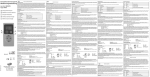
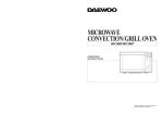
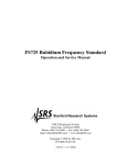
Service Manual
Microwave Oven
Model: KOC-970T1S
KOC-970T2S
KOC-980T10S
KOC-980T20S
DAEWOO ELECTRONICS CO., LTD.
PRECAUTIONS TO BE OBSERVED BEFORE AND
DURING SERVICING TO AVOID POSSIBLE
EXPOSURE TO EXCESSIVE MICROWAVE ENERGY
(a) D o not operate or allow the oven to be operated w ith the door open.
(b) M ake the follow ing safety checks on all ovens to be serviced before activating the m agnetron or other m icrow ave
source, and m ake repairs as necessary: (1) Interlock operation, (2) P roper door closing, (3) S eal and sealing
surfaces (arcing, w ear, and other dam age), (4) D am age to or loosening of hinges and latches, (5) E vidence of
dropping or abuse.
(c) B efore turning on pow er to the m icrow ave oven for any service test or inspection w ithin the m icrow ave
generating com partm ents, check the m agnetron, w ave guide or transm ission line, and cavity for proper
alignm ent, integrity, and connections.
(d) A ny defective or m isadjusted com ponents in the interlock, m onitor, door seal, and m icrow ave generation and
transm ission system s shall be repaired, replaced, or adjusted by procedures described in this m anual before the
oven is released to the ow ner.
(e) A m icrow ave leakage check to verify com pliance w ith the Federal perform ance standard should be perform ed on
each oven prior to release to the ow ner.
SAFETY AND PRECAUTIONS ........................................................................................................ 2
SPECIFICATIONS ................................................................................................................ ............ 3
EXTERNAL VIEW ................................................................................................................. ........... 4
1. OUTER DIMENSION .................................................................................................................... 4
2. FEATURE DIAGRAM .................................................................................................................. 5
INSTALLATION .................................................................................................................. .............. 7
CONTROL PANEL ................................................................................................................. .......... 8
DISASSEMBLY AND ASSEMBLY .................................................................................................. 9
INTERLOCK MECHANISM AND ADJUSTMENT ........................................................................... 18
TROUBLE SHOOTING GUIDE ........................................................................................................ 19
MEASUREMENT AND TEST ........................................................................................................... 25
1. MEASUREMENT OF THE MICROWAVE POWER OUTPUT ..................................................... 25
2. ELECTRICAL CONTINUITY CHECK OF INTERLOCK SWITCH ................................................ 26
3. MICROWAVE RADIATION TEST ................................................................................................ 27
4. COMPONENT TEST PROCEDURE ............................................................................................ 28
WIRING DIAGRAM ................................................................................................................ .......... 29
SCHEMATIC DIAGRAM .................................................................................................................. 30
EXPLODED VIEWS AND PARTS LIST ........................................................................................... 33
PRINTED WIRING BOARD .......................................................................................................... .... 39
P.C.B. CIRCUIT DIAGRAM .............................................................................................................. 44
SAFETY AND PRECAUTIONS
1. FOR SAFE OPERATION
Damage that allows the microwave energy (that cooks or heats the food) to escape will result in poor cooking and may
cause serious bodily injury to the operator.
IF ANY OF THE FOLLOWING CONDITIONS EXIST, OPERATOR MUST NOT USE THE APPLIANCE.
(Only a trained service personnel should make repairs.)
(1) A broken door hinge.
(2) A broken door viewing screen.
(3) A broken front panel, oven cavity.
(4) A loosened door lock.
(5) A broken door lock.
The door gasket plate and oven cavity surface should be kept clean.
No grease, soil or spatter should be allowed to build up on these surfaces or inside the oven.
DO NOT ATTEMPT TO OPERATE THIS APPLIANCE WITH THE DOOR OPEN.
The microwave oven has concealed switches to make sure the power is turned off when the door is opened.
Do not attempt to defeat them.
DO NOT ATTEMPT TO SERVICE THIS APPLIANCE UNTIL YOU HAVE READ THIS SERVICE MANUAL.
2. FOR SAFE SERVICE PROCEDURES.
1. If the oven is operative prior to servicing, a microwave emission check should be performed prior to servicing the oven.
2. If any certified oven unit is found to servicing, a microwave emission check should be performed prior to servicing the oven.
(1) inform the manufacturer, importer or assembler,
(2) repair the unit at no cost to the owner,
(3) attempt to ascertain the cause of the excessive leakage,
(4) tell the owner of the unit not to use the unit until the oven has been brought into compliance.
3. If the oven operates with the door open, the service person should tell the user not to operate the oven and contact
the manufacturer immediately.
IMPORTANT
The w ire in this m ains lead coloured in accordance w ith the following code.
G reen-and-yellow
Blue
Brow n
: Earth
: N eutral
: Live
As the colours of the w ires in the m ains lead of this appliance m ay not correspond w ith the coloured m arkings
identifying the term inals in your plug, proceed as follow s.
The w ire w hich is coloured green-and-yellow m ust be connected to the term inal in the plug which is m arked w ith the
letter 'E' or by earth sym bol or green-and-yellow.
The wire which is coloured blue must be connected to the terminal which is marked with the letter 'N' or coloured black.
The wire which is coloured brown m ust be connected to the term inal which is m arked with the letter 'L' or coloured red.
NOTE
This oven is designed for counter-top use only.
SPECIFICATIONS
M O DE L
KO C-970T1S
KO C-970T2S
PO W E R S UP PLY
230V~50H z
230V~50H z
M IC RO W AV E
1450W
1450W
G RILL
1200W
1200W
C O N VE CTIO N
1550W
1550W
A UTO CO O K
1850W
1850W
C O M BIN ATIO N
2600W (S im ultaneous)
1550W (S equential)
M IC RO WAVE EN ER G Y O U TP UT
1000W (IE C705)
1000W (IE C705)
M IC RO WAVE FR EQ UE NC Y
2450M Hz
2450M Hz
O U TS IDE DIM E N SIO N S (W X H X D )
526 x 345 x 412 m m (20.7 x 13.6 x 16.2 in.)
CAVITY D IM EN SIO NS (W X H X D)
335 x 250 x 339 m m (13.2 x 9.8 x 13.3 in.)
NE T W EIG HT
AP PR O X . 19.5 K g (43 lbs.)
TIM ER
60 m inutes
FU N C TIO N S ELE C TIO N S
M IC R O W AV E /G RILL/C O N VE C TIO N /CO M B I
PO W E R SELE CTIO NS
10 LEVELS
CAVITY V O LUM E
1.0 Cu.Ft.
M O DE L
KO C980T10S
KO C980T20S
PO W E R S UP PLY
230V~50H z
230V~50H z
M IC RO WAVE
1450W
1450W
G R ILL
1200W
1200W
CO NV EC TIO N
1550W
1550W
AU TO CO O K
1850W
1850W
CO M B INATIO N
2600W (S im ultaneous)
1550W (S equential)
M IC RO WAVE EN ER G Y O U TP UT
1000W (IE C705)
1000W (IE C705)
M IC RO WAVE FR EQ UE NC Y
2450M Hz
2450M Hz
O U TS IDE DIM E N SIO N S (W X H X D )
526 x 345 x 482 m m (20.7 x 13.6 x 19.0 in.)
CAVITY D IM EN SIO NS (W X H X D)
335 x 250 x 339 m m (13.2 x 9.8 x 13.3 in.)
NE T W EIG HT
AP PR O X . 21 Kg (46.3 lbs.)
TIM ER
60 m inutes
FU NC TIO N SELE CTIO NS
M ICR O W AV E/G RILL/C O N VECTIO N /CO M BI
PO W E R SELE CTIO NS
10 LE VE LS
CAVITY V O LUM E
1.0 Cu.Ft.
PO W E R C O N SU M PTIO N
PO W E R C O N SU M PTIO N
SPECIFICATIONS ARE SUBJECT TO CHANGE WITHOUT NOTICE.
EXTERNAL VIEW
1. OUTER DIMENSION
KOC-970T
Fig.2 Side view
Fig.1 Front view
KOC980T
Fig.1 Front view
Fig.2 Side view
EXTERNAL VIEW
2. FEATURE DIAGRAM
KOC-970T
1. Door seal - Door seal maintains the microwave energy within the oven cavity and prevents microwave leakage.
2. Door hook - When the door is closed, it will automatically shut. If the door is opened while
the oven is operating, the magnetron will immediately stop operating.
3. Door viewing screen - Allows viewing of food. The screen is designed so that light can pass through, but not the microwave.
4. Top heater - Turns on when convection, grill and combi cooking is selected.
5. Oven lamp - Automatically turns on during oven operating.
6. Safety interlock system
7. Control panel
8. Turntable tray - Rotates during cooking and ensure even distribution of Microwaves.
It can also be used as a cooking utensil.
9. Oven front plate
10. Rotating base - This fits over the shaft in the center of the ovens cavity floor. This is to remain in the oven for all cooking.
It should only be removed for cleaning.
11. Under heater
EXTERNAL VIEW
KOC980T
1. Door seal - Door seal maintains the microwave energy within the oven cavity and prevents microwave leakage.
2. Door hook - When the door is closed, it will automatically shut. If the door is opened while the oven is operating,
the magnetron will immediately stop operating.
3. Door viewing screen - Allows viewing of food. The screen is designed so that light can pass through, but not the microwave.
4. Top heater - Turns on when convection, grill and combi cooking is selected.
5. Oven lamp - Automatically turns on during oven operating.
6. Safety interlock system
7. Control panel
8. Turntable tray - Rotates during cooking and ensure even distribution of Microwaves.
It can also be used as a cooking utensil.
9. Oven front plate
10. Rotating base - This fits over the shaft in the center of the ovens cavity floor. This is to remain in the oven for all cooking.
It should only be removed for cleaning.
11. Under heater
12. Metal rack
INSTALLATION
1. Steady, flat location
This microwave oven should be set on a steady, flat surface.
This microwave oven is designed for counter top use only.
2. Leave space behind and side
All air vents should be kept a clearance. If all vents are covered during operation, the oven may overheat and,
eventually, cause failure.
3. Away from radio and TV sets
Poor television reception and radio interference may result if the oven is located close to a TV, radio, antenna or
feeder and so on. Position the oven as far from them as possible.
4. Away from heating appliances and water taps
Keep the oven away from hot air, steam or splash when choosing a place to position it, or the insulation might be
adversely affected and breakdowns occur.
5. Power supply
• Check your local power source. This microwave oven requires a current of approximately 13amperes, 230 Volts, 50 Hz.
Power supply cord is about 1.2 meters long.
• The voltage used must be the same as specified on this oven. Using a higher voltage may result in a fire or other
accident causing oven damage. Using low voltage will cause slow cooking. We are not responsible for damage
resulting from use of this oven with a voltage of ampere fuse other than those specified.
• This appliance is supplied with cable of special type, which, if damaged, must be repaired with cable of same type.
Such a cable can be purchased from DAEWOO and must be installed by a Qualified Person.
6. Examine the oven after unpacking for any damage such as:
A misaligned door, broken door or a dent in cavity.
If any of the above are visible, DO NOT INSTALL, and notify dealer immediately.
7. Do not operate the oven if it is colder than room temperature.
(This may occur during delivery in cold weather.) Allow the oven to become room temperature before operating.
EARTHING INSTRUCTIONS
This appliance must be earthed. In the event of an electrical short circuit, earthing reduces the risk of the electric shock by providing an escape wire for the electric current. This appliance is equipped with a cord having a earthing wire with a earthing plug.
The plug must be plugged into an outlet that is properly installed and earthed.
WARNING
Im proper use of the earthing plug can result in a risk of electric shock.
C onsult a qualified electrician or servicem an if the earthing instructions are not com pletely understood, or if doubt
exists as to w hether the appliance is properly earthed, and either:
If it is necessary to use an extension cord, use only a 3-w ire extension cord that has a 3-blade earthing plug,
and a 3-slot receptacle that w ill accept the plug on the appliance.
The m arked rating of the extension cord should be equal to or greater than the electrical rating of the appliance,
or Do not use an extension cord.
CONTROL PANEL
W hen blinking, the oven is
operating in "CO M BI"
cooking m ode.
W hen blinking, the oven is
operating in "W EIG H T
D EFRO ST" cooking m ode.
W hen blinking, the oven is
operating in "G RILL"
cooking m ode.
W hen blinking, the oven is
operating in "TIM E
D EFRO ST" cooking m ode.
W hen blinking, the oven is
operating in "M IC RO W AVE"
cooking m ode.
W hen blinking, the oven is
operating in "AUTO CO OK"
cooking m ode.
W hen blinking, the oven is
operating in "PIE"
cooking m ode.
DEFROST
M/W
GRILL
COMBI
AUTO
COOK
PIE
TEMP
COOK
Grill
WEIGHT - TIME
W hen blinking, the oven is
operating in weght input
m ode.
C ooking tim e is increased
by 1 m inute.
KG
+1m in
Com bi
C ooking tim e is increased
by 10 seconds.
Tem p
Pie
+10sec
Function Button-
W hen blinking, the oven is
operating in "CO NVECTIO N"
cooking m ode.
Auto Cook
1.Roast Beef
2.Roast Pork
3.Roast Chicken
4.Fish Fillets
5.Vegetable
Tem perature Button-
STO P/
CLEAR
Used to set desired
tem perature. If this button
is pressed for m ore than
1.3 sec, num ber is
scrolled up autom atically.
M /W
START
Speedy
+
Used to select desired
cooking function.
M /W : M ICRO W AVE
G rill
Defrost : TIM E or W EIG HT
DEFRO ST
Tem p : CO NVEC TION
Com bi : C OM BINATIO N
Pie
Auto Cook
Start ButtonUsed to start the selected
cooking cycle.
Defrost
M icrowave Power LevelU sed to select the variable
m icrowave power level. If
this button is pressed for
m ore than 1.3 sec, num ber
is scrolled up autom atically.
-
Speedy Cook ButtonUsed to program quickly
cooking tim e in 30 sec
increm ents.
Clock
TIM E/W EIGHT
Guide Lam pW hen blinking, it inform s you to
be ready to operate dial knob.
C lock ButtonUsed to set tim e
Dial KnobUsed to set the cooking tim e,
tim e of day and weight input.
DISASSEMBLY AND ASSEMBLY
Cautions to be observed when trouble shooting.
Unlike many other appliances, the microwave oven is high-voltage, high-current equipment.
It is completely safety during normal operation.
However, carelessness in servicing the oven can result in an electric shock or possible danger from a short circuit.
You are asked to observe the following precautions carefully.
1. Always remove the power plug from the outlet before servicing.
2. Use an insulated screwdriver and ware rubber gloves when servicing the high voltage side.
3. Discharge the high voltage capacitor before touching any oven components or wiring.
(1) Check the earthed.
Do not operate on a two-wire extension cord.
The microwave oven is designed to be used with earthed.
It is imperative, therefore, to makes sure it is earthed properly before
beginning repair work.
(2) Warning about the electric charge in the high voltage capacitor.
For about 30 seconds after the operation stopped and electric charge
remains in the high voltage capacitor.
When replacing or checking parts, short between oven chassis and
the negative high terminal of the high voltage capacitor,
by using a properly insulated screwdriver to discharge.
4. When the 15A fuse is blown out due to the operation of the monitor switch;
replace primary interlock switch, secondary interlock
switch and interlock monitor switch.
5. After repair or replacement of parts, make sure that the screws are
properly tightened, and all electrical connections are tightened.
6. Do not operate without cabinet.
CAUTION
Service personnel should rem ove their w atches w henever working close to or replacing the m agnetron.
WARNING
W hen servicing the appliance, need a care of touching or replacing high potential parts because of electrical shock or
exposing m icrowave. These parts are as follow s - H V Transform er, M agnetron, HV C apacitor, H V D iode.
DISASSEMBLY AND ASSEMBLY
1. To remove cabinet
(1) Remove four screws on cabinet back.
(2) Push the cabinet backward.
2. To remove guide wind assembly
(1) Remove two screws for earthing and for fixing to rear-plate.
(2) Remove the noise filter from the guide wind.
(3) Pull the fan from the motor shaft.
(4) Remove two screws which secure the motor shaded pole.
(5) Remove the motor shaded pole.
(6) Reverse the above steps for reassembly.
DISASSEMBLY AND ASSEMBLY
3. To remove H.V.transformer
(1) Remove four screws which secure
the H.V.transformer to the base plate.
(2) Remove the H.V.transformer.
(3) Reverse the above steps for reassembly.
4. To remove high voltage capacitor
(1) Remove a screw which secure the grounding ring
terminal of the H.V. diode and the capacitor holder.
(2) Remove the H.V. diode from the capacitor holder.
(3) Reverse the above steps for reassembly.
High voltage circuit wiring
DISASSEMBLY AND ASSEMBLY
5. To remove magnetron
(1) Remove three screws which secure the magnetron.
(2) Remove the magnetron.
(3) Reverse the above steps for reassembly.
CAUTION
N ever install the m agnetron w ithout the m etallic gasket plate w hich is packed w ith each m agnetron to prevent
m icrow ave leakage. W henever repair w ork is carried out on m agnetron, check the m icrow ave leakage.
It shall not exceed 4m W /cm 2 for a fully assem bled oven w ith door norm ally closed.
DISASSEMBLY AND ASSEMBLY
6. To remove control panel assembly
(1) Remove a screw which secure the control panel assembly to
the oven front plate. At the same time, draw forward the control panel
assembly from the oven front plate.
(2) Remove the dial knob.
(3) Remove nine screws which secure the main and
sub PCB assembly to control panel.
(4) Remove buttons.
(5) Remove the window display and decorator panel.
REF NO.
PART CODE
PART NAME
DESCRIPTION
QTY
REMARK
B 01
3511602400
D EC O R ATO R C -PA NE L
A BS
1
B 02
3515501200
W IN DO W D IS P LAY
P M M A IF-850
1
B 03
3516715110
C O N TR O L-PA N E L
A BS
1
B 04
3516906000
B UTTO N FUN CTIO N
A BS
1
B 05
3516905900
B UTTO N FUN CTIO N
A BS
1
KO R-816
B 06
3516905800
B UTTO N S TA RT
A BS
1
KO R-816
B 07
3516906100
B UTTO N FUN CTIO N
A BS
1
B 08
B 09
PK BP M S Q 200
P C B SU B A S
K O C -970T/980T
1
PK M P M S Q 200
P C B M A IN A S
K O C -970T1S
1
PK M P M S Q 230
P C B M A IN A S
K O C -970T2S
1
PK M P M S YA 00
P C B M A IN A S
K O C 980T10S
1
PK M P M S YA 00
P C B M A IN A S
K O C 980T20S
1
T2S PAN 3x8 MFZN
9
ABS
1
B10
7121300811
SCREW TAPPING
B11
3513403810
KNOB VOLUME
SM O G
KOR-816
DISASSEMBLY AND ASSEMBLY
7. To remove door assembly
(1) Remove two screws which secure the stopper hinge top.
(2) Remove the door assembly from top plate of cavity.
(3) Reverse the above steps for reassembly.
NOTE
After replacing the door assem bly, perform a check of
correct alignm ent w ith the hinge and cavity front plate.
8. To remove door parts
(1) Remove the gasket door.
(2) Remove two screws.
(3) Remove the door seal assy.
REF NO.
(4) Remove the hook and spring.
(5) Remove the supporter and barrier-screen *o.
(6) Remove the handle from the frame door.
PART CODE
PART NAME
DESCRIPTION
QTY
A 01
3512203320
FR AM E DO O R
ABS
1
A 02
3512601400
HA ND LE DO O R
ABS
1
A 03
3517004020
BA RR IER -S CR EE N *O
TE M P ER ED G LAS S T3.2
1
A 04
3515304700
SU PP O RTE R B AR R-S *O
N Y LO N 66
1
A 05
3511708400
DO O R S EA L AS
K O C-971C
1
A 06
3513101100
HO O K
POM
1
A 07
3515101300
SP RIN G HO O K
PW1
1
A 08
3515203600
STO P PE R H IN G E *T AS
K O C-970T1S
1
A 09
7121400811
SC RE W TA PP ING
T2S PA N 4x8 M FZN
2
A 10
3512300800
G A SK ET DO O R
PBT
1
REMARK
DISASSEMBLY AND ASSEMBLY
9. Method to reduce the gap between the door seal and the oven front surface.
(1) To reduce gap located on part ‘A’
• Loosen two screws on stopper hinge top, and then push
the door to contact the door seal to oven front surface.
• Tighten two screws.
(2) To reduce gap located on part ‘B’
• Loosen two screws on stopper hinge under, and then push
the door to contact the door seal to oven front surface.
• Tighten two screws.
(3) To reduce gap located on part ‘C’
• Loosen a screw on interlock switch assembly
located bottom of oven body.
• Draw the interlock switch assembly inward as possible to engage with hook on the door bottom.
• Tighten a screw.
(4) To reduce gap located on part ‘D’
• Loosen a screw on interlock switch assembly located top of oven body.
• Following steps are same as step (3).
NOTE
Sm all gap m ay be acceptable if the m icrow ave leakage does not exceed 1m W /cm 2
NOTE
The door on a m icrow ave oven is designed to act as an electronic seal preventing the leakage of m icrow ave energy
from the oven cavity during the cook cycle. This function does not require that the door be air-tight, m oisture (condensation) Tight or light-tight. Therefore, the occasional appearance of m oisture, light or the sensing of gentle w arm air
m ovem ent around the oven door is not abnorm al and do not of them selves, indicate a leakage of m icrowave energy
from the oven cavity. If such were the case, your oven could not be equipped w ith a bent, the very purpose of w hich
is to exhaust the vapor-laden air from the oven cavity.
DISASSEMBLY AND ASSEMBLY
10. To remove motor syncro and under heater
(1) Cut the syncro motor cover parts from the base plate.
(2) Remove two screws which secure the motor syncro and supporter to bracket syncro motor.
(3) Remove two screws and under heater assembly in cavity
11. To remove grill heater assembly
(1)Remove two screws which secure the cover insulator *t to top plate.
(2) Remove the harness between heaters.
(3) Remove two screws for removing heater brackets.
(4) Remove heaters.
(5) Reverse the above steps for reassembly.
DISASSEMBLY AND ASSEMBLY
12. To remove convection part assembly (KOC980T only)
(1) Remove cover *b and cover insulator *b protecting convection part assembly. - release two lances of cover insulator *b.
(2) Remove four screws which secure the convection part assembly to the cavity rear plate.
(3) Remove a nut holding the convection fan and the pipe.
(4) Remove two screws which secure the bracket motor to cover insulator.
(5) Remove the cooling fan.
(6) Remove two screws which secure the motor shaded pole to the bracket motor.
(7) Reverse the above steps for reassembly.
INTERLOCK MECHANISM AND ADJUSTMENT
The door lock mechanism is a device which has been specially designed to completely eliminate microwave radiation when the
door is opened during operation, and thus to perfectly prevent the danger resulting from the leakage of microwave.
1. Primary interlock switch
When the door is closed, the hook locks the oven door. If the door is not closed properly, the oven will not operate.
When the door is closed, the hook pushes the button of the microswitch.
Then the button of the primary interlock switch bring it under “ON” condition.
2. Secondary interlock switch, door open monitor switch and interlock monitor switch
When the door is closed, the hook pushes the latch lever downward.
The latch lever presses the button of the interlock monitor switch to bring it under “OFF” condition and
presses the button of the secondary interlock switch and door open monitor switch to bring it under “ON” condition.
ADJUSTMENT
Interlock monitor switch
When the door is closed, the interlock monitor switch should be opened before other switches are closed.
When the door is opened, the interlock monitor switch should be closed after other switches are opened.
3. Adjustment steps
(1) Loosen two mounting screws.
(2) Adjust interlock switch assembly position.
(3) Make sure that latch lever moves smoothly after adjustment is completed.
(4) Tighten completely two mounting screws.
NOTE
Microwave emission test should be performed after adjusting interlock mechanism.
If the microwave emission exceed 4mW/cm2, readjust interlock mechanism.
TROUBLE SHOOTING GUIDE
Following the procedures below to check if the oven is defective or not.
1. Check grounding before checking trouble.
2. Be careful of the high voltage circuit.
3. Discharge the high voltage capacitor.
4. When checking the continuity of the switches, fuse or high voltage transformer, disconnect one lead wire from these parts
and then check continuity with the AC plug removed. To do otherwise may result in a false reading or damage to your meter.
NOTE
W hen electric parts are checked, be sure the pow er cord is not inserted the w all outlet.
Check wire harness, wiring, and connected of the term inals and pow er cord before check parts listed below.
(TROUBLE 1) Oven does not operate at all; any inputs can not be accepted.
CON DITION
CHECK
Fuse blow s.
C heck co ntinuity of
interlock m onitor sw itch
w ith door closed
(C O M N C)
RESULT
(C O M N C)
C ontinuity
(C O M N C)
CAUSE
REM EDY
M alfunction
of interlock
m on itor
sw itch
R eplace
N O TE 1
M alfunction
of interlock
sw itch
R eplace
N O TE 1
S horted
contacts of
prim ary
interlock
sw itch
R eplace
D efective low
voltage
transform er
R eplace
D efective
high voltage
transform er
R eplace
N o C ontinuity
C heck co ntinuity of both
prim ary and secondary
interlock sw itch w ith
door closed
No
C ontinuity
C ontinuity
C heck co ntinuity of
prim ary interlock sw itch
contact with door
partially open until
interlock m onitor sw itch
contact close
(C O M N C close)
C ontinuity
C heck co ntinuity of
prim ary w inding of low
voltage transform er
0 Ω or infinite
D isconne ct high voltage
fuse and operate the unit
Fuse again
blows
A pprox.
150~210
(norm al)
N O TE 1
TROUBLE SHOOTING GUIDE
CON DITION
CHECK
RESULT
CAUSE
REM EDY
O utlet has
proper voltage
Fuse does not
blow.
C heck con tinuity of
m agn etron
No
C ontinuity
D efective
m agn etron
R eplace
C heck con tinuity of noise
filter board
No
C ontinuity
D efective
noise filter board
R eplace
C heck con tinuity of
pow er supply cord
No
C ontinuity
O pen pow er
supply cord
A djust
N orm al
D efective
touch control
circuit
A djust
NOTE
All these sw itches m ust be replaced at the sam e tim e, please refer to (7.Interlock M echanism and Adjust)
for adjustm ent instructions.
(TROUBLE 2) Grill heater (top heater) is not heated; Food will not become hot.
CON DITION
CHECK
RESULT
CAUSE
REM EDY
G rill heater is
not heated.
C heck continuity of
prim ary interlock sw itch
No
C ontinuity
M alfunction
of prim ary
interlock sw itch
A djust or
R eplace
C heck continuity of
secondary interlock sw itch
No
C ontinuity
M alfunction
of secondary
interlock sw itch
A djust or
R eplace
C heck continuity of
heater
No
C ontinuity
D efective
heater
R eplace
C heck D .C. voltage
being supplied to
R ELAY (R Y2) coil
0V
D efective
touch control
circuit
R eplace
A pprox
12 VD C
Faulty
contacts of
R ELAY
(RY 2) or open
relay coil
R eplace
TROUBLE SHOOTING GUIDE
(TROUBLE 3) No microwave oscillation even though fan motor rotates.
CON DITION
CHECK
RESULT
N o m icrowave
oscillation
C heck con tinuity of high
voltage fuse
No
Continuity
CAUSE
REM EDY
R eplace high voltage fuse
C heck con tinuity of high
voltage capacitor
term inals w ith w ires
rem oved
Continuity
Defective
high voltage
transform er
Replace
C heck con tinuity of high
voltage rectifier in
forw ard and backw ard
direction with D C
m egg er
Continuity in
backw ard
direction
Defective
high voltage
rectifier
Replace
C onnect m egger leads to
m agn etron term inal and
m agn etron body
Continuity
Defective
m agnetron
Replace
C heck resistance of
prim ary and secondary
coil of high voltage
transform er
0 Ω or Defective
high voltage
transform er
Replace
C heck con tinuity of
m agn etron w ith w ires
rem oved
No
Continuity
Defective
m agnetron
Replace
C heck con tinuity of
filam ent term inal of high
voltage transform er
No
Continuity
Defective
high voltage
transform er
Replace
C heck D .C. voltage
being supplied to
R ELAY (R Y3) coil
0V
Defective
touch control
circuit
Replace
Approx
13 VDC
Faulty
contacts of
RELAY
(RY3) or open
relay coil
Replace
TROUBLE SHOOTING GUIDE
(TROUBLE 4) Display shows all figures selected, but oven does not start cooking,
even though desired program and time are set and start pad is tapped.
C O N D ITIO N
C H EC K
R ESU LT
C AU SE
R EM ED Y
Turn table
m oto r and
oven lam p do
not turn on
C heck con tinuity of
prim ary interlock sw itch
No
C ontinuity
M alfunction
of prim ary
interlock
sw itch
A djus t or
replace
C heck con tinuity of
secondary interlock and
D .O .M . sw itch
No
C ontinuity
M alfunction
of secondary
interlock and
D .O .M . sw itch
A djus t or
replace
C heck D .C . voltage
being supplied to
R ELAY (R Y4) coil
0V
D efective
touch control
circuit
R eplace
A pprox.
13 VD C
F aulty
contacts of
R ELAY
(R Y 4) or open
relay coil
R eplace
(TROUBLE 5) 1) Under heater is not heated; Food will not become hot.
2) Convection motor does not rotate.
C O N D ITIO N
C H EC K
R ESU LT
C AU SE
R EM ED Y
1) U nde r hea ter
is n ot heated.
2) C onv ection
fan and m otor
does n ot rotate.
C heck con tinuity of
prim ary interlock sw itch
No
C ontinuity
M alfunction
of prim ary
interlock
sw itch
A djus t or
replace
C heck con tinuity of
secondary interlock sw itch
No
C ontinuity
M alfunction
of secondary
interlock sw itch
A djus t or
replace
C heck con tinuity of
heater (m otor)
No
C ontinuity
D efective
heater(m otor)
R eplace
C heck D .C . voltage
being supplied to
R ELAY (R Y6) coil
0V
D efective
touch control
circuit
R eplace
A pprox.
13 VD C
F aulty
contacts of
R ELAY
(R Y 6) or open
relay coil
R eplace
TROUBLE SHOOTING GUIDE
(TROUBLE 6) The following visual conditions indicate a probable defective touch control circuit or button P.C.B. assembly.
1. Incomplete segments
(1) Segments missing
(2) Partial segments missing
(3) Digit flickering other than normal fluorescent slight flickering
(4) 0 does not display when power is on.
2. A distinct change in the brightness of one or
more numbers exists in the display.
3. One or more digits in the display are not on
when they should be.
4. Display indicates a number different from one touched.
(for example, even if one touched 5, 3 appears in the display.
5. Specific numbers (for example, 2 or 3) do not display
when the button is touched.
6. Display does not count down or up with time cooking or
clock operation.
7. Oven is programable and cooks normally but no display shows.
8. Display obviously jumps in time while counting down.
9. Display counts down noticeably too fast while cooking.
10. Display does not show the time of day when clear button is touched.
11. Oven lamp and turntable motor do not stop although cooking is finished.
Check if the RELAY (RY3) contacts close and if they are close, replace touch control circuit.
CON DITION
CHECK
RESULT
CAUSE
REM EDY
D isplay does
not show
program m ing
at all, even if
keyboard is
touched.
C heck each button for
continuity of the button
keyboard for the
following keyboard
check procedure
N orm al
M alfunction
of touch
control circuit
of control box
sub-a ssem bly
R eplace
control box
sub-a ssem bly
N orm al
M alfunction
of botton
keyboard
R eplace
the button
keyboard
NOTE
Before follow ing the particular steps listed above in the trouble shooting guide for the button keyboard’s failure,
please check for the continuity of each w ire-harness betw een the button keyboard and P.C .B. assem bly.
TROUBLE SHOOTING GUIDE
BUTTON KEYBOARD CHECK PROCEDURE
1. Type of button names
( key metrix and circuit diagram )
The tact switch keyboard consists of 10 keys which configurations are described above.
2. Key check procedure
To determine if the tact switch keyboard is defective or not, check the continuity of each
button(key) contacts with a multimeter.
(1) AUTO COOK
button : between 4 and 10
(2) DEFROST
button : between 4 and 14
(3) TEMP
button : between 8 and 12
(4) MICROWAVE
button : between 6 and 14
(5) COMBI
button : between 6 and 12
(6) GRILL
button : between 2 and 10
(7) +10 SEC
button : between 8 and 10
(8) +1 MIN
button : between 6 and 10
(9) STOP/CLEAR
button : between 2 and 12
(10) START
button : between 4 and 12
(11) CLOCK
button : between 8 and 14
(12) PIE
button : between 2 and 14
MEASUREMENT AND TEST
1. MEASUREMENT OF THE MICROWAVE POWER OUTPUT
Microwave output power can be checked by indirectly measuring the temperature rise of a certain
amount of water exposed to the microwave as directed below.
PROCEDURE
1. Microwave power output measurement is made wit the microwave oven supplied at rated voltage and operated at its
maximum microwave power setting with a load of 1000 ± 5cc of potable water.
2. The water is contained in a cylindrical borosilicate glass vessel having a maximum material thickness of 3 mm and
an outside diameter of approximately 190 mm.
3. The oven and the empty vessel are at ambient temperature prior to the start of the test.
The initial temperature of the water is 10 ± 2 °C (50 ± 3.6 °F).
It is measured immediately before the water is added to the vessel.
After addition of the water to the vessel, the load is immediately placed on the center of the shelf,
which is in the lowest normal position.
4. Microwave power is switched on.
5. Heating time should be exactly A seconds.
Heating time is measured while the microwave generator is
operating at full power.
The filament heat-up time for magnetron is not included.
6. The initial and final temperature of water is selected so that the maximum
difference between the ambient and final water temperature is 5K.
7. The microwave power output P in watts is calculated from the following formula:
P = 4187 T/t
• DT is difference between initial and ending temperature.
• t is the heating time.
The power measured should be B (refer to 2. Specifications)W ± 10.0 %.
CAUTION
1. Water load should be measured exactly to 1 liters.
2. Input power voltage should be exactly specified voltage(Refer to 2. SPECIFICATIONS).
3. Ambient temperature should be 20 ± 2 °C (68 ± 3.6°F)
Heating time for power output:
A(second)
70
64
60
56
52
49
47
44
42
40
38
B(W )
600
650
700
750
800
850
900
950
1000
1050
1100
MEASUREMENT AND TEST
2. ELECTRICAL CONTINUITY CHECK OF INTERLOCK SWITCH
NOTE
R em ove the power plug from the w all receptacle before testing.
PROCEDURE
1. Primary interlock switch
(1) Disconnect two connectors from primary interlock switch.
(2) Connect the ohm-meter leads between the terminals of the primary interlock switch.
2. Read the value of resistance between the terminals of the switch, when the door is opened, and when the door is closed.
3. Secondary interlock switch
(1) Disconnect two connectors from secondary interlock switch.
(2) Connect the ohm-meter leads between the terminals of the secondary interlock switch.
(3) Read the value of resistance between the terminals of the switch, when the door is opened,
and when the door is closed.
3. Monitor interlock switch
(1) Disconnect the lead wire connecting the primary interlock switch and interlock monitor switch from
primary interlock switch terminal.
(2) Connect the ohm-meter leads between the lead wire connector disconnected as item1 and
the power supply neutral plug pin.
(3) Read the value of resistance between the lead wire connector and the power supply neutral plug pin,
when the oven door is opened, and when the oven door is closed.
JUDGEMENT
• The value of resistance should be applied to the value specified below.
Switch
Door Open
Door Close
Prim ary interlock sw itch
0
Secondary interlock sw itch
0
Interlock m onitor circuit
0
• When value obtained is not acceptable, the switch should be replaced or adjusted again.
MEASUREMENT AND TEST
3. MICROWAVE RADIATION TEST
WARNING
M ake sure to check the m icrowave leakage before and after repair of adjustm ent.
Always start m easuring of an unknown field to assure safety for operating personnel from m icrow ave energy.
D o not place your hands into any suspected m icrowave radiation field unless the safe density level is know n.
C are should be taken not to place the eyes in direct line w ith the source of m icrow ave energy.
Slow ly approach the unit under test until the radiom eter reads an appreciable m icrow ave leakage from the unit
under the test.
PROCEDURE
1. Prepare Microwave Energy Survey Meter, 600cc glass beaker,
and glass thermometer 100°C (212°F ).
2. Pour 275cc ±15cc of tap water initially at 20 ± 5 °C (68 ± 9°F)
in the 600 cc glass beaker with an inside diameter of approx.
95 mm(3.5 in.).
3. Place it at the center of the tray and set it in a cavity.
4. Close the door and operate the oven.
5. Measure the leakage by using Microwave Energy Survey Meter
with dual ranges, set to 2450MHz.
• Measured radiation leakage must not exceed the value prescribed below.
Leakage for a fully assembled oven with door normally
closed must be less than 4mW/cm2.
• When measuring the leakage, always use the 5 cm (2 in.)
space cone with probe.
Hold the probe perpendicular to the cabinet and door.
Place the space cone of the probe on the door, cabinet, door seem,
door viewing screen, the exhaust air vents and the suction air vents.
• Measuring should be in a counter-clockwise direction at a rate of 1 in./sec.
If the leakage of the cabinet door seem is unknown, move the probe more slowly.
• When measuring near a corner of the door, keep the probe perpendicular to
the areas making sure the probe end at the base of the cone does not get closer than 2 in. from any metal.
If it does not, erroneous reading may result.
MEASUREMENT AND TEST
4. COMPONENT TEST PROCEDURE
High voltage is present at the high voltage terminal of the high voltage transformer during any cooking cycle.
It is neither necessary nor advisable to attempt measurement of the high voltage.
Before touching any oven components or wiring, always unplug the oven from its power source and discharge the capacitor.
1. High voltage transformer
(1) Remove connections from the transformer terminals
and check continuity.
(2) Normal readings should be as follows :
Secondary winding ... Approx. 100 10%
Filament winding ... Approx. 0.1
Primary winding ... Approx. 1.5
2. High voltage capacitor
(1) Check continuity of capacitor with meter on the highest OHM scale.
(2) A normal capacitor will show continuity for a short time,
and then indicate 9M once the capacitor is charged.
(3) A shorted capacitor will show continuous continuity.
(4) An open capacitor will show constant 9M
(5) Resistance between each terminal and chassis should be infinite.
3. High voltage diode
(1) Isolate the diode from the circuit by disconnecting the leads.
(2) With the ohmmeter set on the highest resistance scale measure the resistance across the diode terminals.
Reverse the meter leads and again observe the resistance reading.
Meter with 6V, 9V or higher voltage batteries should be used to check the front-back resistance of the diode,
otherwise an infinite resistance may be read in both directions.
A normal diode's resistance will be infinite in one direction and several hundred kin the other direction.
4. Magnetron
For complete magnetron diagnosis, refer to "Measurement of the Microwave Output
Power." Continuity checks can only indicate and open filament or a shorted magnetron.
To diagnose for an open filament or a shorted magnetron,
(1) Isolate magnetron from the circuit by disconnecting the leads.
(2) A continuity check across magnetron filament terminals should indicate 0.1 or less.
(3) A continuity check between each filament terminal and magnetron case should read open.
5. Fuse
If the fuse in the primary and monitor switch circuit is blown when the door is opened, check the primary and monitor switch
before replacing the blown fuse.
In case the fuse is blown by an improper switch operation, replace the defective switch and fuse at the same time.
Replace just the fuse if the switches operate normally.
WIRING DIAGRAM
SCHEMATIC DIAGRAM
SCHEMATIC DIAGRAM
SCHEMATIC DIAGRAM
EXPLODED VIEWS AND PARTS LIST
1. KOC-970T
EXPLODED VIEW
EXPLODED VIEWS AND PARTS LIST
PARTS LIST
REF NO.
A 00
PART CODE
PART NAME
DESCRIPTION
QTY
3511708310
DO O R A S
KO C-970T
1
P KC PS W Q 200
CO NTRO L-PA N EL AS
KO C-970T1S
1
P KC PS W Q 230
CO NTRO L-PA N EL AS
KO C-970T2S
1
F1
3516107910
CAVITY W E LD AS
KO C-970T
1
F2
3516503300
RE AR -PLATE *O
SB HG -1 TO .6
1
F3
3514800800
SE NS O R TE M P ER ATUR E
PTM -K312-D4
1
F4
7113400814
SC RE W TA PP ING
T1 BIN 4*8 M FN I
1
F5
3511403800
CO VE R W AV E G UIDE
M ICA TO .5
1
F6
7113400814
SC RE W TA PP ING
T1 BIN 4*8 M FN I
1
F7
3514400600
PIP E
BR AS S C 3604B D
1
F8
3517401300
CO UP LE R
CE RA M IC
1
F9
3966510200
M O TO R SY NC RO
230V 25W G M -16-24FD 24
1
F10
7121400811
SC RE W TA PP ING
T2S PAN 4*8 M FZN
2
F11
3510604000
BR AC KE T M O TO R S Y NC RO
SE CC TO .8
1
F12
7113400814
SC RE W TA PP ING
T1 BIN 4*8 M FN I
1
F13
3512802100
HE ATER *U AS
KO C-971CO S
1
F14
7113400814
SC RE W TA PP ING
T1 BIN 4*8 M FN I
2
F15
3510310400
BA SE
SB HG -1 T0.8
1
F16
3515202810
STO P PE R H IN G E *U A S
KO C-970T
1
F17
7S422X 4081
SC RE W S PE C IA L
TT2 TRS 4*8 SE M FZN
2
F18
3512100900
FO O T
PP, D AS F-130
4
F19
4416W 67820
CA PA CITO R H V
2100VA C , 1.1 U F
1
F20
441X304112
HO LD ER HV CAPA CITO R
SECC TO .8
1
F21
7S422X 4081
SC RE W S PE C IA L
TT2 TRS 4*8 SE M FZN
1
F22
4416V24000
DIO D E H V
SA NK EN HV R-1X-32B (D5.3)
1
F23
3518112100
TR AN S H V
DY -90S0-97T1
1
F24
7S427W 40A 1
SC RE W S PE C IA L
TT2 H EX FG 4*10 S E M FZN
4
F25
7S312X 40A 1
SC RE W S PE C IA L
T1 TR S 4*10 SE M FZN
6
F26
3513809100
LO CK
PO M
1
F27
3513601600
LA M P
BL 240V25W T25 C 7A H187
1
F28
5S762S 10G 0
SW M ICR O
SZM -V16-FA -63
2
F29
5S762310G 0
SW M ICR O
SZM -V16-FA -61
2
F30
3513701300
LE VE R LO CK
PO M
1
F31
7S341W 40B 1
SC RE W S PE CIA L
T2S PAN 4*12 P W SE M FZN
2
F32
7S341W 40B 1
SC RE W S PE CIA L
T2S PAN 4*12 P W SE M FZN
1
F33
7S422X 4081
SC RE W S PE C IA L
TT2 TRS 4*8 SE M FZN
1
F34
3517502700
PR O TEC TO R H EATE R
M ICA M T56 T1.0
2
B 00
REMARK
EXPLODED VIEWS AND PARTS LIST
REF NO.
PART CODE
PART NAME
DESCRIPTION
QTY
F35
3510603610
BR AC KE T H EATE R *T
SE CC T0.6
2
F36
7S312X 40A 1
SC RE W S PE C IA L
TT2 H EX FG 4*10 M FZN
2
F37
3512803000
HE ATER M IRA CLO N
115V 550W
2
F38
3512765100
HA RN ES S H EATE R
#187 FLA G 65M M
1
F39
3517302500
FO AM
CR 10T*180*30
1
F40
3518002400
M A G N ETRO N
2M 218J(M F)I
1
F41
7S427W 40A 1
SC RE W S PE C IA L
TT2 H EX FG 4*10 S E M FZN
3
F42
3511800100
FA N
PP G F20
1
F43
3512505200
G U ID E W IND
PP
1
F44
3963513000
M O TO R SH AD ED PO LE
230V25W O E M -15D W C2-A03
1
F45
7121403011
SC RE W TA PP ING
T2S PAN 4*30 M FZN
2
F46
7S341W 40B 1
SC RE W S PE CIA L
T2S PAN 4*12 P W SE M FZN
1
3518604600
NO IS E -FILTER
DW LF-P (KO C-970T1S )
1
3518605500
NO IS E -FILTER
DW LF-M O 7(KO C-970T2S )
1
4417B67600
FU SE
15A 250V (K O C-970T1S )
1
5F1CD 1232M
FU SE
12A 250V (K O C-970T2S )
1
7S312X 40A 1
SC RE W S PE C IA L
T1 TR S 4*10 SE M FZN
1
35113A 5Q 5J
CO RD P O W ER AS
3*1.5(KO C-970T1S )
1
35113A 5Q M 5
CO RD P O W ER AS
3*1.0(KO C-970T2S )
1
F51
7S312X 40A 1
SC RE W S PE C IA L
T1 TR S 4*10 SE M FZN
2
F52
7S427W 40A 1
SC RE W S PE C IA L
TT2 H EX FG 4*10 S E M FZN
2
F53
3512505500
G U ID E A IR O UTLE T
SA 1D -80 TO .5
1
F54
7S312X 40A 1
SC RE W S PE C IA L
T1 TR S 4*10 SE M FZN
1
F55
3511404800
CO VE R INS U LATO R *T
SE CC TO .5
1
F56
7S312X 40A 1
SC RE W S PE C IA L
T1 TR S 4*10 SE M FZN
1
F57
3510801900
CA BIN ET
PC M TO .5
1
F58
7S312X 40A 1
SC RE W S PE C IA L
T1 TR S 4*10 SE M FZN
4
F59
3512513000
G U ID E TRAY A S
KO C-971CO S
1
F60
3517205200
TR AY M ETAL
SP P TO .6
1
F61
3518700220
FU SE HV
5K V 0.7A TH VO 60T
1
F47
F48
F49
F50
REMARK
EXPLODED VIEWS AND PARTS LIST
2. KOC-980T
EXPLODED VIEW
EXPLODED VIEWS AND PARTS LIST
PARTS LIST
REF NO.
A 00
PART CODE
PART NAME
DESCRIPTION
Q’TY
3511708310
DO O R AS
K O C 980T
1
PKC P SW YA00
CO NTRO L-PAN EL AS
KO C 980T10S (SIM UL.)
1
P KC P SW YA00
CO NTRO L-PAN EL AS
K O C 980T20S (SE Q U EN TIA L)
1
F01
3516107950
CAVITY W E LD A S
K O C 980TI0S
1
F02
3518904400
TH E RM O S TAT
120/60, #187
1
F03
7121400611
SC RE W TAP PIN G
T2S PA N 4*6 M FZN
1
F04
7112400811
SC RE W TAP PIN G
T1 TRS 4X 8 M FZN
1
F05
3511403800
CO VE R W AV E G UID E
M IC A TO .5
1
F06
7113400814
SC RE W TAP PIN G
T1 B IN 4*8 M FNI
1
F07
3514400600
PIP E
B RA SS C3604BD
1
F08
3517401300
CO UP LER
CE R AM IC
1
B 00
F09
3966510200
M O TO R S YN CR O
230V 25W G M -16-24FD 24)
1
F10
7121400811
SC RE W TAP PIN G
T2S PA N 4*8 M FZN
2
F11
3510604000
BR A CK ET M O TO R SY NC RO
S EC C TO .8
1
F12
7113400814
SC RE W TAP PIN G
T1 B IN 4*8 M FNI
1
F13
3512802100
HE ATER *U AS
K O C -971C O S
1
F14
7113400814
SC RE W TAP PIN G
T1 B IN 4*8 M FNI
2
F15
3510310400
BA S E
S BH G TO .8
1
F16
3515202800
STO P PE R H ING E *U A S
K O R -121M O A
1
F17
7S 422X4081
SC RE W S PE CIA L
TT2 TR S 4*8 S E M FZN
2
F18
3512101400
FO O T
P P, DA SF-130
4
F19
4416W 67820
CA PA CITO R H V
2100VA C , 1.1 U F
1
F20
441X304112
HO LDER HV CAPA CITO R
S EC C TO .8
1
F21
7S 422X4081
SC RE W S PE CIA L
TT2 TR S 4*8 S E M FZN
1
F22
4416V 24000
DIO DE HV
S AN KE N H VR -1X -32B(D 5.3)
1
F23
3518112100
TR A NS H V
DY -N90S0-97T1
1
F24
7S 427W 40A 1
SC RE W S PE CIA L
TT2 HE X FG 4*10 SE M FZN
4
F25
7S 312X40A 1
SC R E W S PE C IA L
T1 TRS 4*10 S E M FZN
5
F26
3513809100
LO C K
POM
1
F27
3513601600
LAM P
B L 240V 25W T25 C7A H 187
1
F28
5S 762S10G 0
SW M ICR O
S ZM -V 16-FA-63
2
F29
5S 762310G 0
SW M ICR O
S ZM -V 16-FA-61
2
F30
3513701300
LEV ER LO CK
POM
1
F31
7122401211
SC RE W TAP PIN G
T2S TR S 4*12 M FZN
2
F32
7122401211
SC RE W TAP PIN G
T2S TR S 4*12 M FZN
1
F33
7S 422X4081
SC RE W S PE CIA L
TT2 TR S 4*8 S E M FZN
1
F34
3517502700
PR O TE CTO R H EATE R
M IC A M T56 T1.O
2
F35
3510603610
BR A CK ET HE ATER *T
S EC C TO .6
2
F36
7S 312X40A 1
SC R E W S PE C IA L
T1 TRS 4*10 S E M FZN
2
F37
3512803000
HE ATER M IR AC LO N
115V 550W
2
F38
3512765100
HA RN E SS HE ATER
#187 FLAG 65M M
1
REMARK
EXPLODED VIEWS AND PARTS LIST
REF N O.
PAR T CODE
PART NA ME
DESCRIPTION
Q’TY
F 39
3517302500
FOAM
C R 10T *180*30
1
F 40
3518002400
M A G NE T R O N
2M 218J(M F )I
1
F 41
7S 427W 40A 1
S C R EW S P EC IA L
T T2 H E X F G 4*10 S E M F Z N
3
F 42
3511800100
FA N
P P G F 20
1
F 43
3512505200
G U IDE W IN D
PP
1
F 44
3963513000
M O TO R S H A DE D P O LE
230V 25W O EM -15D W C2-AO 3
1
F 45
7112403011
S C R EW TA P P IN G
T 2S PA N 4*30 M F ZN
2
F 46
7122401211
S C R EW TA P P IN G
T 2S T R S 4*12 M F Z N
1
3518604600
N O IS E-F ILT E R
D W LF -P (K O C 980T 10S )
1
3518605500
N O IS E-F ILT E R
D W LF -M O 7(K O C 980T20S )
1
4417B 67600
FUSE
15A 250V(K O C 980T 10S)
1
5F 1C D 1232M
FUSE
12A 250V(K O C 980T 20S)
1
7112401011
S C R EW TA P P IN G
T 1 T R S 4*10 M FZ N
1
35113A5Q 5J
CORD POWER AS
3*1.5(K O C980T 10S )
1
35113A5Q M 5
CORD POWER AS
3*1.0(K O C980T 20S )
1
F 51
7112401011
S C R EW TA P P IN G
T 1 T R S 4*10 M FZ N
2
F 52
7S 427W 40A 1
S C R EW S P EC IA L
T T2 H E X F G 4*10 S E M F Z N
2
F 53
3512505500
G U IDE A IR O U T LET
S A1D -80 T O .5
1
F 54
7112401011
S C R EW TA P P IN G
T 1 T R S 4*10 M FZ N
1
F 55
3511404800
C O V ER IN S ULATO R *T
S EC C TO .5
1
F 56
7112401011
S C R EW TA P P IN G
T 1 T R S 4*10 M FZ N
1
F 57
3510801000
C A B INE T
P CM TO .5
1
F 58
7112401011
S C R EW TA P P IN G
T 1 T R S 4*10 M FZ N
4
F 59
3512513000
G U IDE T R AY AS
K O C -971C O S
1
F 60
3517205200
T R AY M E TA L
S PP TO .6
1
F 61
3514800800
S E N SO R T EM P E RATU R E
PT M -K 312-D4
1
F 62
7113400814
S C R EW TA P P IN G
T 1 B IN 4*8 M F NI
1
F 63
3518700220
FUSE HV
5KV 0.7A
1
F 64
3511401300
C O V ER IN S ULATO R *B
S BH G -1 0.6T
1
F 65
3510601500
B R A CK E T M O TO R
S BH G -1 0.8T
1
F 66
3963513200
M O TO R S H A DE D P O LE
O EM -10DW C 2-A 09
1
F 67
7051400811
S C R EW M AC H IN E
PA N 4*8 S W M F Z N
2
F 68
441B629071
FA N
S BH G -1 0.6T
1
F 69
3514400400
P IP E
A L1100
1
F 70
3511401800
C O V ER IN S ULATO R
S A1D -80 0.7T
1
F 71
3511800400
FA N CO N V EC T IO N
S A1D -80 0.5T
1
F 72
7121400811
S C R EW S P EC IA L
N UT F LAN G E M 4 M F ZN
1
F 73
7S 627W 50X 1
S C R EW TA P P IN G
T 1 T R S 4*8 T B -W M F ZN
1
F 74
7S 627W 50X 1
S C R EW TA P P IN G
T 1 T R S 4*8 T B -W M F ZN
4
F 75
3511402100
C O V ER *B
P.P
1
F 47
F 48
F 49
F 50
REMA RK
PRINTED WIRING BOARD
1. CIRCUIT CHECK PROCEDURE
(1) Low Voltage Transformer(DMR-101FS) check
- The low voltage transformer is located on the P.C.B.
- Measuring condition (input voltage) : 230 VAC / 50 Hz
KOC-970T/980T
L.V.T. : DMR-101FS
Terminal
Voltage
1-2
230VAC/50Hz
4-5
13.0 VAC
6-7
35.0 VAC
8 - 10
3.0 VAC
• Secondary side voltage of the low voltage transformer changes in proportion to fluctuation of power source voltage.
• The allowable tolerance of the secondary voltage is within ±5% of normal voltage.
(2) Voltage check
- Key check point ( 1~4:Micom Pin, 5:Display Pin )
NO
CHECK POINT
REMARK
1
P IN 63, 64
0V
2
P IN 29, 32, 62
-5 VD C ± 5%
3
P IN 45
4
P IN 30, 31
5
P IN 1, 25
2.6 VAC (D isplay filam ent voltage)
- Check method
NO
VOLTAGE
REMARK
KOC-970T/980T
1
-5 V D C
R eplace R24, J3, Q 10
2
-12 V DC
R eplace D1~D6, J8
3
-27 V DC
R eplace R28, R 29, ZD 4
NOTE
The m arks of the above corresponding voltages (+5, +12, -24VD C) are written on the PC B .
Each m easuring points m ust be m easured with G ND points.
PRINTED WIRING BOARD
(3) Display Problems
NO
CAUSE
MEASUREMENT
RESULT
REMEDY
1
P oor contact between P.C .B.
and display filam ent
C heck the voltage of display pin 1 & 25
2
The display has som e
trouble in its segm ent orgrid
R efer to The display trouble shooting
data below
Replace P.C .B.
assem bly
3
Loss vacuum in the display
Find white spot
Replace P.C .B.
assem bly
2.6 VA C
Fix the pin 1 & 25 on
the P.C.B .
- The display trouble shooting data
TROUBLE
DISPLAY NAME & PIN NO.
MICOM OUTPUT IN PIN NO.
M /W & AU TO C O O K don’t com e on.
G rid 1 (G 1), 21
24
G R ILL & P IE don’t com e on.
G rid 2 (G 2), 17
17
CO M B I & TE M P CO O K don’t com e on.
G rid 3 (G 3), 14
18
W E IG H T DE FRO ST & K g don’t com e on.
G rid 4 (G 4), 10
16
TIM E D EFRO ST don’t com e on.
G rid 5 (G 5), 4,7
13
Segm ent a doesn’t com e on from G 1 to G 5
Segm ent a, 23
26
Segm ent b doesn’t com e on from G 1 to G 5
Segm ent b, 22
25
Segm ent c doesn’t com e on from G 1 to G 5
Segm ent c, 20
23
Segm ent d doesn’t com e on from G 1 to G 5
Segm ent d, 19
22
Segm ent e doesn’t com e on from G 1 to G 5
Segm ent e, 18
21
Segm ent f doesn’t com e on from G 1 to G 5
Segm ent f, 16
20
Segm ent g doesn’t com e on from G 1 to G 5
Segm ent g, 15
19
Segm ent h doesn’t com e on from G 1 to G 5
Low er bar h, 5
14
Segm ent i doesn’t com e on from G 1 to G 5
Upper bar i, 6,8,9,11
15
PRINTED WIRING BOARD
(4) Case of no microwave oscillation
(a) Situation : When touching M/W button, oven lamp turns on, fan motor and turntable motor rotate and cook indicator in
the display comes on.
⇒ CAUSE : Relay 3 (RY3) does not operate.
KOC-970T/980T
- Check method
STAGE
POINT A
POINT B
R E LAY 3 O N
-5 VD C
GND
R E LAY 3 O FF
GND
-12 V D C
(b) Situation : When touching M/W button, oven lamp does not turn on and turntable motor does not rotate but cook
indicator in the display comes on.
⇒ CAUSE : Relay 4 (RY4) does not operate.
KOC-970T/980T
- Check method
STAGE
POINT A
POINT B
R E LAY 4 O N
-5 VD C
GND
R E LAY 4 O FF
GND
-12 V D C
(c) Situation : When touching M/W button, oven lamp turns on and fan motor does not rotate but cook indicator in
the display comes on.
⇒ CAUSE : Relay 5 (RY5) does not operate.
KOC-970T/980T
PRINTED WIRING BOARD
- Check method
STAGE
POINT A
POINT B
R E LAY 5 O N
-5 VD C
GND
R E LAY 5 O FF
GND
-12 V D C
(5) Case of no heating of upper heater
When touching “TEMP COOK & COMBI” button, oven lamp turns on, fan motor and
turntable motor rotate and cook indicator in the display comes on.
⇒ CAUSE : Relay 2 (RY2) does not operate.
KOC-970T/980T
- Check method
STAGE
POINT A
POINT B
R E LAY 2 O N
-5 VD C
GND
R E LAY 2 O FF
GND
-12 V D C
(6) Case of no heating of lower heater
When touching TEMP COOK & PIE button, oven lamp turns on, fan motor and
turntable motor rotate and cook indicator in the display comes on.
⇒ CAUSE : Relay 6 (RY6) does not operate.
KOC-970T/980T
- Check method
STAGE
POINT A
POINT B
R E LAY 6 O N
-5 VD C
GND
R E LAY 6 O FF
GND
-12 V D C
PRINTED WIRING BOARD
(7) Case of no stopping of the count down timer
When the door is opened during operation, the count down timer does not stop.
KOC-970T/980T
- Check method
STAGE
POINT A
POINT B
Door opened
O pen
-5 V DC
Door closed
Closed
G ND
NOTE
C heck the state (O N , O FF) of the secondary interlock sw itch by resistance m easurem ent.
(8) Case of appearring Err6 on the display
KOC-970T/980T
- Check method
POINT
W AVEFORM
A
B
C
NOTE
If clock does not keep exact tim e, you m ust check Diode D7 & Transistor Q 2.
P.C.B. CIRCUIT DIAGRAM
1. KOC-970T/980T
P.C.B. CIRCUIT DIAGRAM
2. KOC-970T/980T PCB ASS’Y PART LIST
NAME
PC B
TR A N S P O W ER
SYMBOL
SPECIFCATION
PART CODE
Q ′TY
M 208
92X 195
3514314920
1
M 209
86X 159.5
3514314930
1
LV T1
D M R -101FS
5E P V041351
1
PP
3513002600
1
HO LDE R VFD
BU ZZE R
BZ1
B M -20K
3515600100
1
D IG ITR O N
DP1
S VM -5S S13
D S VM 5SS 13-
1
RE S O N ATO R C ER A
CR 1
C ST4.00M G W
5P C ST400M G
1
IC1
M B89143A P -218,970T
141SC 870T0
1
M B89143A P -244,980T
141SC 980T0
1
IC M IC O M
R C AB O N FILM
R17
1/4W, 4.7K O H M J
RD -4Z472J-
1
R C AB O N FILM
R22
1/4W, 100K O H M J
RD -4Z104J-
1
R C AB O N FILM
R13,18,21
1/4W,10K O HM J
RN -4Z103J-
3
R C AB O N FILM
R28,29
1/4W,2K O H M J
RD -4Z202J-
2
R C AB O N FILM
R12,19,20,27,30
1/4W,1K O H M J
RD -4Z102J-
5
R C AB O N FILM
R31
1/4W,4.7 O H M J
RD -4Z479J-
1
R C AB O N FILM
R11
1/6W,20K O HM J
RD -AZ563J-
1
R C AB O N FILM
R3,4,14,15
1/6W,10K O HM J
RD -AZ103J-
4
R C AB O N FILM
R5,6,7,9
1/6W,4.7K O HM J
RD -AZ472J-
4
R C AB O N FILM
R2,8
1/6W,1K O H M J
RD -AZ102J-
2
R C AB O N FILM
R10
1/6W,330 O HM J
RD -AZ331J-
1
R C AB O N FILM
R16
1/6W,510 O HM J
RD -AZ511J-
1
R C AB O N FILM
R1
1/6W,100 O HM J
RD -AZ101J-
1
R C AB O N FILM
R23
1/4W,10K O HM F
RN -4Z1002F
1
R C AB O N FILM
R24
1/4W,120K O H M F
RN -4Z1203F
1
DIO DE SW ITCH ING
D7
1N4148M
DZN4148M -
1
DIO DE RE CTIFIE R
D2~6,D 8~12
1N4002A
DZN4002A --
10
DIO DE ZE NER
ZD 1
M TZ 3.9B
DZTZ3R9B-
1
DIO DE ZE NER
ZD 2
U Z 5.6B
DZTZ5R6B-
1
DIO DE ZE NE R
ZD 3
M TZ 27B
DZTZ27B --
1
DIO DE ZE NER
ZD 4
M TZ 4.7B
DZTZ4R7B-
1
C E LE C TR O
EC 1
R S 50V 10 U F
CE XE 1H 100A
1
C E LE C TR O
EC 4
R SS 35V 1000 U F
CE XF1V102V
1
C E LE C TR O
EC 2,E C 3
R SS 50V 220 U F
CE XF1H221V
2
C A RR AY
CA 1
8P(7)50V 1000 P F
CN 7X B -102M
1
C C ER A A XIA L
C1,4,5~9,12~14
H 1K F 50V 0.1uFZ
CC KF1H104Z
10
C C ER A A XIA L
C10,11
H 1K F 50V 1000pZ
CC ZB 1H102Z
2
C C ER A A XIA L
C2,3
H 1K F 50V 0.47uF
CC KF1H473Z
2
P.C.B. CIRCUIT DIAGRAM
NAME
SYMBOL
SPECIFCATION
PART CODE
Q ′TY
CO NN EC TO R W AFE R
CN 2
35312-0310
30166M 5030
1
CO NN EC TO R W AFE R
CN 1
35313-0210
30166M 7020
1
CO NN EC TO R W AFE R
CN 4
35328-0610
4C W 3061M X 0
1
CO NN EC TO R FILM
CN 3
H LE M 15S-1
4C W 215SBD 0
1
TR A N S IS TO R
Q 1,2,10
K TA 1270Y
TZTA 1270Y-
3
TR A NS IS TO R
Q 6~9,11
K RA 102M
TZRA 102M -
5
TR A N S IS TO R
Q 3,4
K R C 102M
TZR C 102M -
2
RE LAY
RY 2,RY 3
G 5J-1-TP-M -D T-12
5S C 0101112
2
R E LAY
RY 4~6
G 5B -1-12V
5S C 0101110
3
R A RR AY
RA 1~R A3
8P (7) 1/8 100K J
RA -88X 104J
3
CO NN EC TO R FILM
CN 101
H LE M 15R-1
4C W 21RB D0
1
SW TA CT
SW 101~112
K PT-1115AM
5S 50101Z93
12
SW RO TA RY
EN 101
S DB 161VB 17F-12-36-36P C(PITCH 5)
5S 10109002
1
DAEWOO ELECTRONICS CO., LTD
686, AHYEON-DONG MAPO-GU
SEOUL, KOREA
C.P.O. BOX 8003 SEOUL, KOREA
TELEX : DWELEC K28177-8
CABLE : “DAEWOOELEC”
E-mail : [email protected]
FAX : 02) 360-8184
TEL: 02) 360-8178~8182
S/M NO. : C970T1S001
PRINTED DATE : JUL. 19988