1
DMB-3003LH 2003.3.4 9:57 AM 페이지20
OWNER'S MANUAL
MODEL #:
DMB-3003LH
S1
DMB-3003LH 2003.3.4 9:56 AM 페이지1
SAFETY INSTRUCTIONS
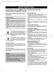
PLEASE READ THE FOLLOWING SAFETY INSTRUCTIONS BEFORE INSTALLING AND OPERATING THE UNIT:
This air conditioner meets strict safety and operating standards. The
installer of this unit must install or service this unit so it operates safely and efficiently.
Precautions When Wiring:
• Do not plug in the unit until all connections (tubing, drain hose,
mounting, etc.) have been made and double-checked.
• High voltages are present in this unit and are very dangerous.
Please refer to these instructions and diagrams when wiring.
Improper connections or inadequate grounding can cause accidental injury.
• This unit must be grounded in accordance with local electrical
codes.
• Connect wires and pipes securely and tightly as loose connections/wiring may cause overheating at connections and a possible
fire hazard.
IMPORTANT NOTES
• Adhere to all safety instructions and warnings throughout this
manual.
• Read this manual carefully before installing or operating this
unit to become familiar with its features and obtain the performance that will bring you continued enjoyment for many
years.
• Follow each installation or repair step exactly as shown in the
manual.
• Observe all local, state and national electric codes. Contact
your local government for more information on electrical
codes.
Precautions When Transporting:
• When transporting the unit, be very careful and get help as the
units are very heavy. Be careful of sharp edges on the units also.
Precautions When Installing:
• When installing in a ceiling or wall, make sure the ceiling/wall is
strong enough to hold the unit’s weight. A frame may be necessary
for added support.
• When installing in a room, make sure the tubes are well insulated to protect the walls and furniture from sweating of the tubes.
• When installing in moist or uneven locations, make sure to use
a raised level concrete pad or concrete blocks to provide a level,
solid foundation for the outdoor unit; this prevents water damage
and vibration.
• When installing in an area of high winds, make sure to securely
anchor the outdoor unit down with bolts and a metal frame.
The lightning flash with arrowhead symbol, within
an equilateral triangle is intended to alert the user to
the presence of uninsulated dangerous voltage
within the product’s enclosure that may be of sufficient magnitude to constitute a risk of electric shock
to persons.
The exclamation point within an equilateral triangle
is intended to alert the user to the presence of important operating and maintenance (servicing) instructions in the literature accompanying the appliance.
When Connecting Refrigerant Tubing:
• Keep all tubing as short as possible.
• Use the flare method for connecting tubing.
• Apply refrigerant lubricant to the matching surfaces of the flare and
union tubes before connecting them, then tighten , making sure not
to overtighten.
• Check the tubes carefully for leaks before starting the test run.
Contact Installer if Necessary:
The installation instructions are for a experienced installer. If you are
not an experienced installer, contact a local installer for help. If you
require help with service, contact your certified dealer or Daewoo
Electronics for additional instructions.
When Servicing:
If Unit is Installed Improperly:
The manufacturer shall in no way be responsible for improper installation or maintenance service, including failure to follow the instructions in this manual.
• Make sure the power is off and the unit is unplugged before opening the unit to troubleshoot or repair electrical parts and wiring.
• Keep your fingers and clothing away from any moving parts.
• Clean up the sight after you finish, making sure no metal scraps
and wiring are left in the unit.
• The Air conditioner shall be installed in accordance with the nationed wiring regulation.
• The equipment fulfills the requirements in EN 61 000-3-11 and is
subject to conditional connection to the mains.
• It may be connected in consultation with the supply authority.
• The equipment may only be connected to a mains supply with a
system impedance of less than 0.3 ohm.
• The system impedance in the interface point may be obtained
from the supply authority.
• If the mains supply has a higher system impedance, short voltage
dips may appear when the equipment is started or during operation.
• This may influence or disturb the operation of other apparatuses, e.
g. flickering lamps, especially those connected to the same supply
mains.
WARNING:
• ELECTRICAL SHOCK CAN CAUSE SEVERE PERSONAL INJURY OR DEATH. ONLY A QUALIFIED, EXPERIENCED ELECTRICIAN/INSTALLER SHOULD ATTEMPT TO WIRE THIS SYSTEM.
• THE APPLIANCE IS NOT INTENDED FOR USE BY CHILDRENOR INFIRM PERSONS WITHOUT SUPERVISION.
• YOUNG CHILDREN SHOULD BE SUPERVISED TO ENSURE
THAT DO NOT PLAY WITH THE APPLIANCE
1
DMB-3003LH 2003.3.4 9:56 AM 페이지2
ROOM AIR CONDITIONER INSTRUCTION
Remark per EMC Directive 89/336/EEC
To prevent flicker impressions during the start of the compressor (technical process) following installation conditions do apply.
1. The power connection for the air conditioner has to be done at the main power distribution. This distribution has to be of an low
impedance. Normally the required impedance is reached at a 32A fusing point. Air conditioner fuse has to be 16A max!
2. No other equipment has to be connected to this power line.
3. For detailed installation acceptance please refer to your contract with the power supplier.
If restrictions do apply for products like washing machines, air conditioners or electrical ovens.
4. For power details of the air conditioner refer to the rating plate of the product.
CONSIGINES D’INSTALLATION RACCORDEMENT ELECTRIQUE
Remarques relatives à la Directive EMC 89/336/CEE
Pour eviter les phénormènes de scintillements(variation de lumière) et les parasites lors du démmarrage du compresseur, respecter
les consignes d’installation décrites dans le mode d’emploi.
1. Le raccordement au secteur doit être-fait à l’aide d’un cable de section suffisante pour eviter tout échauffement de celui-ci et les
chutes de tension (section recommandée 3x4mm2)
Cette ligne doit être protégée par un fusible ou disjoncteur de 16A
2. Aucun autre appareil ne doit être connecté sur cette ligne.
3. En cas de doute ou de difficulté contactez votre agence EDF. Vériflez qu’il nexiste pas de contraintes particulères pour l’instalation et l’utilisation de ce climatiseur.
4. Pour les caractéristiques de l’appareil référez vous à sa plaque signalétique.
INSTRUCCIONES DE INSTALACION DEL AIRE ACONDICIONADO
Comentario de la Directiva 89/336 EEC de la EMC.
ára prevenir la sensación de golpeteo al arrancar el compresor(procesotécnico) debe aplicar las siguientes instrucciones de instalación
1. La conexión del aire acondicionado a la corriente eléctrica tiene que ser hecha a la distribución principal de energía. Esta distribución
tiene que ser de baja impedancia. Normalmente, la impedancia requerida se alcanza en el punto de fusión de 32A. El fusible del aire
acondicionado tiene que ser de 16A máximol.
2. Ningún otro equipo debe ser conectado a esta línea eléctrica.
3. Para normas detalladas de instalación por favor consulte el contrato con su suministador eléctrico, si tiene que aplicar restricciones
para productos como lavadoras, aire acondicionado u homos eléctricos.
4. Para detalles sobre las alimentación eléctrica del aire acondicionado consulte la placa de datos del aparato.
ANWEISUNGEN ZUR INSTALLATION DER RAUM-KLIMAANLAGE
Hinweis entsprechend EMV-Direktive 89/336/EEC
Um einen “Flicker-Effekt” beim Anlauf des Kompressors (kurzzeitiger Spannungseinbruch, technischer Vorgang) zu vermeiden, muß für folgende installationsbedingungen gesorgt sein. (siche auch “Anweistingen zur installation.”)
1. Der Stromanschluß für die Klimpaanlage muß am Hauptverteller vorgenommen werden. Die Abzweigung muß mit niedriger Impedanz ausgeführt werden. Normalerweise ist die erforderliche niedrlge impedanz bei einem Sicherungsanschlußpunkt von 32A erreicht.
2. An die gleíche Netzleitung dürfen keine anderen Geráte angeschlossen sein.
3. Seitens der lokaten Energieversorgungsuntemehmen bestehen möglicherweise Einschránkungen für Produkte wie Waschmaschinen,
Klimaanlagen, elektrische Öfen, etc. Für Einzelheiten zur Installation sehen Sie in Ihren Vertrag mit dem Energieversorgungsunternehmen.
4. Einzelheiten über die elektrischen Daten der Kimaanlage ersehen Sie auf dem Typenschild des Gerates.
INSTRUZIONI PER L’INSTALLAZIONE DEL CONDIZIONATORE
D’ARIA PER STANZE
NOTA DELLA DIRETTIVA EMC 89/336 EEC
Allo scopo di prevenire l’ effetto di FLICKER (variazione della luce) alla partenza del compressore, durante l’installazione seguire l punti sottoelencatl.
1. Il collegamento dell’ alimentazione, del condizionatore, deve essere fatto con una linea preferenziale dlrettamente al quadro principale o
contatore, e deve essere a bassa impedenza.
Normalmente questa lmpedenza la si ottiene al punto di fusione di 32 A ; perll condizionatore usare un fusibile da 16 A max.
2. Nessun altro apparecchio elettrico dovra essere collegato alla stessa linea di alimentazione.
3. Per maggiori dettagll circa l’ accettazione dell’ installazione del condizionatore, fare riferimento al contratto con l’ Ente erogatore dell’
Energla Elettrica e verificare che non ci siano restrizioni in atto all’ Installazione di prodottl elettrici ad alto consumo.
4. Per le informazioni relative ai dati di allmentazlone del condizionatore, fare riferimento all’ etichetta posta sul prodotto.
2
DMB-3003LH 2003.3.4 9:57 AM 페이지3
CONTENTS
It is recommended that you read the Installation and Operating instructions fully before installing and/or operating this unit.
Safety Instructions............................................................................................................................................... 1
Contents................................................................................................................................................................ 3
Configuration ....................................................................................................................................................... 4
Location of Controls............................................................................................................................................ 5
Indoor Unit ...........................................................................................................................................................................5
Outdoor Unit ........................................................................................................................................................................5
Remote Controller ...............................................................................................................................................................7
Remote Display ...................................................................................................................................................................7
Operation .............................................................................................................................................................. 8
Connecting the AC Cord .....................................................................................................................................................8
Setting the Unit for Remote Operation................................................................................................................................8
How to Install Batteries........................................................................................................................................................9
Celsius to Fahrenheit Conversion Chart.............................................................................................................................9
To Set Auto Mode .............................................................................................................................................................10
To Set Quick Mode ...........................................................................................................................................................10
To Set Cool Mode .............................................................................................................................................................10
To Set Only Fan Mode......................................................................................................................................................11
To Set Dehumidifier Mode ................................................................................................................................................11
To Set Heat Mode .............................................................................................................................................................12
To Select The Fan Direction .............................................................................................................................................12
To Set On Timer Mode......................................................................................................................................................13
To Set Off Timer Mode......................................................................................................................................................13
To Set Sleep Mode ...........................................................................................................................................................14
To Set Turbo/Mild Mode....................................................................................................................................................14
Emergency Operation .......................................................................................................................................................14
Installation Diagram ..........................................................................................................................................................15
AC Connection Diagram .....................................................................................................................................................16
Changing/Cleaning the Air Filters.................................................................................................................................17
Cleaning the Indoor Cover ..............................................................................................................................................17
Care and Maintenance ......................................................................................................................................................18
Troubleshooting Guide ....................................................................................................................................................19
3
DMB-3003LH 2003.3.4 9:57 AM 페이지4
CONFIGURATION
Unit A
Unit B1
Unit B2
A
B1
B2
Capacity
Indoor Unit
A
B1
B2
Cooling (W)
Heating (W)
3220
3500
Min
2560
Min
2490
Max
3370
Max
3520
Min
2560
Min
2490
Max
3370
Max
3520
4
DMB-3003LH 2003.3.4 9:57 AM 페이지5
LOCATION OF CONTROLS
INDOOR UNIT
(Cold or hot)
Air Out
OUTDOOR UNIT
Service Cover
Remove this cover to access
the AC connection from this
unit to the indoor unit.
A
B1
B2
5
Service Valve
The indoor units and outdoor
unit are connected by
copper tubes which are
connected here.
DMB-3003LH 2003.3.4 9:57 AM 페이지6
INDOOR UNIT DISPLAY
Indoor Unit Display
Switch Panel
■Remote Control Signal Receiver
This place is the part to receive the signal if it receives
the signal, you can hear the signal “beep”.
EMR. REMOCON
ON (Red)
Lights-on
during the operation
Timer (Yellow)
Lights-on during the time
of reservation mode.
Air clean (Green)
Lights-on
during the operation
Quick (Red)
Lights-on during the time
of Quick Mode.
■ When the remote controller is lost or outof-order, push the emergency button
(EMR.) to operate by hand.
Open the front panel on emergency operating.
Remocon switch is usually used with remote controller.
6
DMB-3003LH 2003.3.4 9:57 AM 페이지7
REMOTE CONTROLLER
DMB-3003LH
Display
Displays information
pertaining to unit.
AUTO
FAN SPEED Button
Press to select the fan speed
(High " ", Middle " ", Low " ").
MODE Button
Press to cycle through the modes
(Auto/Quick/Cool/Fan/Dehumidifier/Heat)
SLEEP Button
Press to set the unit for
the sleep mode.
ON/OFF Button (Red)
Press to turn the unit
on or off.
TEMPERATURE Buttons
Press to raise or lower
the desired temperature.
MODE
FAN SPEED
FAN DIR.
SLEEP
FAN DIR.
Button
Press to select up/down
direction for fan.
TIMER
ON/OFF
ENTER/
CANCEL
TURBO/MILD
TURBO/MILD
Press to select super-power operation
(Tubro) mode
TIMER ON/OFF Button
Press to set the unit off or on time.
(0.5, 1, 1.5, 2, 2.5, 3, 4, 5, 6, 8,
10, 12, 16, 20, 24hr)
TIMER ENTER/CANCEL Button
Press to enter a timer setting or
to cancel timer setting
COVER
Slide down to access most
of the remote buttons.
Slide down further to
access the battery
compartment.
REMOTE DISPLAY
MODE Indicators (Auto/Quick/Cool/Fan/Dehumidifier/Heat)
Lights to indicate the mode selected.
AUTO
FAN Indicators
Lights to indicate
the fan speed.
FAN DIRECTION Indicators
Lights to indicate the
fan direction.
NATURAL Indicators
Lights to indicate the
speeds simulating a breeze.
TIMER Indicators (Include sleep)
Lights to indicate the timer function mode.
TEMPERATURE & RESERVATION TIME Indicators
Lights to indicate the temperature or time.
7
DMB-3003LH 2003.3.4 9:57 AM 페이지8
OPERATION
CONNECTING THE AC CORD
Only the power plug of outdoor unit is connected to AC outlet, and the power of indoor units were supplied with AC connection cords from outdoor unit. To supply the system with AC power, follow the procedures bellow:
1. Insert the AC
plug of outdoor
unit into a
pronged 220V
AC outlet
NOTES:
• Never connect the AC line cord plug to other than the
specified voltage (220V).
• The new air conditioner system should be on it’s own
220V circuit. Contact your local electrical installer for installation.
• Use the recommended power cord and wire only (refer
to page 15)
AC Outlet
and Plug
Plug into 220V AC Outlet. (not supplied)
SETTING THE UNIT FOR REMOTE OPERATION
After the unit is fully connected and plugged in, it can be turned on. To turn the unit on and set it for remote operation,
follow the procedures below:
2. Press the ON/OFF button on the remote controller to
turn on the unit. The On LED will light on the indoor
unit and “ON” will light in the remote display.
To select the various modes
and settings, read the following pages.
1. Open the indoor unit’s cover and make sure the EMERGENCY/REMOTE switch is set to the REMOTE position;
this will allow the unit to operate with the remote controller.
EMERGENCY/REMOTE Switch
THREE MINUTE COMPRESSOR DELAY
• After turning the indoor unit on and setting it for air conditioner operation, the compressor (outdoor unit) will
not come on for three minutes. This is a feature that
will protect the compressor from damage due to quick
start and stops.
EMR. REMOCON
8
DMB-3003LH 2003.3.4 9:57 AM 페이지9
HOW TO INSTALL BATTERIES
To install the batteries, follow the procedures below:
TIMER
ON/OFF
ENTER/
CANCEL
TURBO/MILD
+
–
2. Insert two “AAA” size
Alkaline batteries following the polarity diagram
below.
1. Slide down the cover to access
most of the remote buttons. Slide
down further to access the battery
compartment.
–
+
BATTERY PRECAUTIONS
The precautions below should be followed when using batteries in this device:
1. Use only the size and type of batteries specified.
2. Be sure to follow the correct polarity when installing the batteries as indicated in the battery compartment. Reversed
batteries may cause damage to the device.
3. Do not mix different types of batteries together (e.g. Alkaline and Carbon-zinc) or old batteries with fresh ones.
4. If the device is not to be used for a long period of time, remove the batteries to prevent damage or injury from possible
battery leakage.
5. Do not try to recharge batteries not intended to be recharged; they can overheat and rupture. (Follow battery manufacturer’s directions).
CELSIUS TO FAHRENHEIT CONVERSION CHART
CELSIUS
FAHRENHEIT
CELSIUS
FAHRENHEIT
18
64.4
26
78.8
19
66.2
27
80.6
20
68
28
82.4
21
69.8
29
84.2
22
71.6
30
86
23
73.4
31
87.8
24
75.2
32
89.6
25
77
CAUTION-IN CASE OF OPERATING TWO UNITS
the operation mode of the remote controller
CASE I
indoor unit B1
indoor unit B2
Operation
Fan
Heating
Heating
Fan
Cooling
Heating
CASE II
Heating
Cooling
Fan
Cooling
No Good
Cooling
Fan
Cooling
Cooling
Cooling Dehumidification
Dehumidification Cooling
Heating
Heating
Good
As shown above, When the “CASE I” is selected, only the indoor unit which is received the first signal from the remote controller operates and the other indoor unit doesn’t operate.
also, you can see the blink of indicators of the latter.
in that case, try to select one out of the “CASE II” again.
9
DMB-3003LH 2003.3.4 9:57 AM 페이지10
TO SET AUTO MODE
This unit will automatically operate the unit according to its surroundings while in the Auto mode. All you have to set is
the desired temperature and it will control the fan, coolness and dehumidifier. Follow procedures below:
1. Press the ON/OFF button on the remote control to
turn the unit on; the On LED will light on the indoor
unit and “ON” will light in the
remote display.
2. Make sure the AUTO indicator AUTO appears in the remote
display. Using the TEMP. ▼ or ▲ buttons, set the desired
temperature. The desired temperature can be changed up
or down 1 degree from the actual
room temperature. For temperature setting: 24~28°C
3. Then the unit will automatically operate.
AUTO
TO SET QUICK MODE
To set this unit to cool at the highest power, follow the procedures below:
1. Press the ON/OFF button on the remote control to
turn the unit on; the On LED will light on the indoor
unit and “ON” will light in the remote display.
2. Press the MODE button until the Quick indicator
appears in the display.
3. The unit will then start cooling the room at the highest
power.
TO SET COOL MODE
To set the unit to cool the room to a desired temperature, follow the procedures below:
1. Press the ON/OFF button on
the remote control to turn the
unit on; the On LED will light
on the indoor unit and “ON”
will light in the remote display.
2. Press the MODE button until the Cool
indicator
appears in the display.
3. Using the TEMP. ▼ or ▲ buttons, set the desired
temperature. The desired temperature can be changed up to
32°C and down to 18°C.
4. To select the fan speed, press the FAN
SPEED button until the desired speed
appears in the display (see below).
FAN SPEEDS
“AUTO”
“ ”
“ ”
“ ”
“NATURAL”
AUTO
10
The fan will automatically select the fan speed.
The fan will operate on low speed.
The fan will operate on medium speed.
The fan will operate on high speed.
The fan will randomly cycle through the speeds
simulating a cool breeze.
DMB-3003LH 2003.3.4 9:57 AM 페이지11
TO SET ONLY FAN MODE
To operate only the fan so the unit will circulate the air, proceed as follows:
1. Press the ON/OFF button on the remote control to
turn the unit on; the On LED will light on the indoor
unit and “ON” will light in the remote display.
2. Press the MODE button until the Fan indicator
appears in the display.
No allowance setting temperature
3. To select a fan speed, press the FAN SPEED button
until the desired speed appears in the display (see below).
FAN SPEEDS
“ ”
“ ”
“ ”
“NATURAL”
NOTE:
The fan will operate on low speed.
The fan will operate on medium speed.
The fan will operate on high speed.
The fan will randomly cycle through the
speeds simulating a breeze.
• If “NATURAL” is selected, the NATURAL” indicator on
the indoor unit will light.
TO SET DEHUMIDIFIER MODE
Select this mode when there is high humidity. To select, follow the procedures below.
1. Press the ON/OFF button on the remote control to
turn the unit on; the On LED will light on the indoor
unit and “ON” will light in the remote display.
2. Press the MODE button until the Dehumidifier indicator
appears in the display.
3. Using the TEMP. ▼ or ▲ buttons, set the desired temperature. The desired temperature can be changed up
to 32°C and down to 18°C.
11
DMB-3003LH 2003.3.4 9:57 AM 페이지12
TO SET HEAT MODE
To set the unit to heat the room to a desired temperature, follow the procedures below:
1. Press the ON/OFF button on the remote control to
turn the unit on; the On LED will light on the indoor
unit and “ON” will light in the
remote display.
2. Press the MODE button until the Heat indicator
appears in the display.
In the heat mode, the fan direction
▼ or ▲ is further downward than
that in the cool mode for the good
circulation.
3. Using the TEMP. ▼ or ▲ buttons, set the desired
temperature. The desired temperature can be
changed up to 32°C and
down to 18°C.
4. To select the fan speed, press the FAN
SPEED button until the desired speed
appears in the display (see below).
NOTE:
When the heating orperation is started, hot air delivery
might be delayed due to warm up period.
FAN SPEEDS
“AUTO”
The fan will automatically select the fan
speed.
“ ”
The fan will operate on low speed.
“ ”
The fan will operate on medium speed.
“ ”
The fan will operate on high speed.
“NATURAL” The fan will randomly cycle through the
speeds simulating a cool breeze.
TO SELECT THE FAN DIRECTION
Regardless of the mode the unit is set for, the fan direction can be changed so it moves up and down.
Follow procedures below to set fan direction.
1. Press the ON/OFF button on the remote control to
turn the unit on; the On LED will light on the indoor
unit and “ON” will light in the
remote display.
3. Press the FAN DIR. button to select
the fan direction. See chart below
for detailed information on each of
the three settings.
2. Press the MODE button to select the desired mode.
FAN DIR.
FAN DIR.
First Press
The air will flow up
and down.
Second
Press
Normal air direction.
12
DMB-3003LH 2003.3.4 9:57 AM 페이지13
TO SET ON TIMER MODE
This unit can be set to automatically turn on after a predetermined amount of hours (up to 24) in the order of 0.5, 1, 1.5,
2, 2.5, 3, 3.5, 4, 5, 6, 8, 10, 12, 16, 20, 24.
1. Press the ON/OFF button of timer on the remote control to set the on timer mode, “HOUR” and “ON” on the remote
display will be displayed and “TIMER” will be flicked. When you increase to press “ON/OFF” you will get desired
time. Then, if pressing “ENTER/CANCEL” button, ON TIMER Mode will be started. If you want to stop ON TIMER
Mode, please press “ENTER/CANCEL” again.
2. While the unit is off, press the TIMER
ON button; the display will light waiting
input for the timer, but the actual unit
will not turn on.
4. Press the ENTER button to input the setting into
memory; the unit will beep, the TIMER indicator will
light on the unit and the TIMER indicator on the remote will light to indicate the unit is in the timer mode.
3. Repeatedly press the TIMER ON button until the desired hour that you want the unit to turn on appears
on the display. For example, if it is
1:00 P.M. and you want the unit to
turn on at 4:00 P.M., select 3 hours.
5. Place the remote controller so it is facing the unit.
When the desired hour is reached, the unit will turn on
to the selected mode.
AUTO
NOTE : Press the ENTER button within 5 seconds
of selecting the desired time. If mote than 5 seconds elapse, steps 3 and 4 must be repeated.
TO SET OFF TIMER MODE
This unit can be set to automatically turn off after a predetermined amount of hours (up to 24) in the order of 0.5, 1, 1.5,
2, 2.5, 3, 3.5, 4, 4.5, 5, 5.5, 6, 6.5, 7, 7.5, 8, 8.5, 9, 9.5, 10, 11, 12, 16, 20, 24.
1. Press the ON/OFF button of timer on the remote control to set the off timer mode, “HOUR” and “OFF” on the remote display will be displayed and “TIMER” will be flicked. When you increase to press “ON/OFF” you will get desired time. Then, if pressing “ENTER/CANCEL” button, OFF TIMER Mode will be started. If you want to stop OFF
TIMER Mode, please press “ENTER/CANCEL” again.
2. Press the TIMER OFF button once to
enter the Timer screen.
AUTO
4. Press the ENTER button to input the setting into
memory; the unit will beep, the TIMER indicator will
light on the unit and the TIMER indicator on the remote will light to indicate the unit is in the timer mode.
3. Repeatedly press the TIMER OFF button until the desired hour that you want the unit to shut off appears
on the display. For example, if it is
8:00 P.M. and you want the unit to
turn off at 10:00 P.M., select 2 hours.
5. When the desired hour is reached, the unit will turn
off.
AUTO
NOTE: Press the ENTER button within 5 seconds
of selecting the desired time. If more than 5 seconds elapse, steps 3 and 4 must be repeated.
13
DMB-3003LH 2003.3.4 9:57 AM 페이지14
TO SET SLEEP MODE
When you are going to sleep, select this feature and the unit will cool off the room to the desired temperature and then
increase that temperature throughout the night.
1. Press the ON/OFF button on the
remote control to turn the unit
on; the On LED will light on the
indoor unit and “ON” will light in
the remote display.
2. Press the MODE button to select the
desired mode. Then, set the desired
temperature using the TEMP. ▲ or ▼
buttons.
3. Press the SLEEP button on the remote
controller. The unit will then be in the sleep
mode and will cool the room to the desired
temperature. After a while the unit will increase the temperature again in the cooling
mode or decrease the temperature in the heat mode of
the heat pump. This process will then repeat.
TO CANCEL SLEEP MODE:
To cancel sleep mode,
press the SLEEP button
again; the SLEEP indicator
will disappear in the display.
AUTO
TO SET TURBO/MILD MODE
1. The unit is fixed “MILD” mode on production.
2. Press the “TURBO/MILD” button for powerful cooling.
3. When press the “TURBO/MILD” button one more time, it will be back to “MILD” mode.
EMERGENCY OPERATION
If the remote control is lost, broken or has no batteries, follow the procedures below:
2. The unit will then turn on and depending on the room
temperature, it will select the cool or heat, fan speed
and fan direction automatically.
1. Open the indoor unit’s cover and make sure the
EMERGENCY/REMOTE switch is set to the EMERGENCY position.
EMERGENCY/REMOTE Switch
EMR. REMOCON
3. To turn the unit off, slide or push the EMERGENCY/ REMOTE switch to the REMOTE position.
14
DMB-3003LH 2003.3.4 9:57 AM 페이지15
INSTALLATION DIAGRAM
Below is an overview for the connection of the Indoor unit to the Outdoor unit. The pages following will give detailed
instructions for full installation. Remember to read the complete Installation section and follow all the safety instructions
fully when installing the Indoor and Outdoor units.
OVERVIEW
This appliance must be installed according to national power supply acquirement.
10cm (3.95in)
from ceiling
30cm (11.8in) from
side wall
10cm (3.95in) from
side wall
Connecting cable
(Not supplied)
Wall
10cm (3.95in) from
side wall
30cm (11.8in)
from side wall
10cm (3.95in) from
side wall
Drain
Hose
Wall
Cap
Wall
Bracket
At least 30cm
(11.8in) from unit
Pipes
(Not Supplied)
Signal wire
1
cm 0
23.6 60
inches cm
Wrap with
Tape
Maximum Height 7M (21Ft)
Maximum Length 15M (49Ft)
3.9 inches
60 m
c
• After installation it must be
possible for the user to
disconnect the power supply
plug.
• If the AC outlet is a 3-pronged
type or other, have an
electrician install a new
outlet.
• Contanct service man when
replace the power cord set.
Drain
Hose
Copper
Tubing
NOTES:
Ground Wire
(Not Supplied)
23.6
inches
Connecting
cable
AC Outlet
and Plug
Signal Wire
Plug into 220V~240V
AC Outlet
(Not supplied)
15
3/8" side piping
1/4" side piping
Drain Hose
The added refrigerant according to the extention tube
length: 30g/m [Standard length: 7.5m]
- Adding additional tubing will decrease efficiency.
DMB-3003LH 2003.3.4 9:57 AM 페이지16
AC CONNECTION DIAGRAM
You should individually connect wires to terminals as bellow diagram:
Terminal Block
Terminal Block
Terminal Block
Indoor Unit B2
Indoor Unit B1
Indoor Unit A
L
BRN
Y/G
N
L
BLU
BRN
Connection
Cable
BLU
N
Y/G
L
BLU
BRN
Connection
Cable
Y/G
BLU
BRN
N3
L3
Y/G
N2
Unit B2
N
Y/G
BLU
Connection
Cable
BRN
L2
BLU
Y/G
N1
Unit B1
BRN
L1
Unit A
BLU
N
BRN
L
Power
Terminal Block
Outdoor
NOTE: We want you to observe bellow recommended specifications.
Part Name
Recommended specifications
Power plug
250V 16A
Power cable
Flexible, H05RN-F above 2.0mm2
Circuit breaker
20A
Connection cable
H05RN-F 0.5 or above x 3P x 8m
16
Y/G
DMB-3003LH 2003.3.4 9:57 AM 페이지17
CHANGING/CLEANING THE AIR FILTERS
To change or clean the two black air filters, follow the procedures below:
1. Open the indoor unit’s
cover and remove both
black air filters by bending
them slightly backward
and the lifting out.
2. Remove the two small
filters (Deodorizing and
Electrostatic) from the
indoor unit.
3. Examine the filters and determine if they need to be
cleaned or replaced. To clean filters, use a vacuum and
clean off dust. Use water and mild soap also if necessary.
4. Insert cleaned or new
small filters (Deodorizing
and Electrostatic) back
into the unit.
5. Insert cleaned or new black
filters back into the unit.
NOTES:
• The filters should be changed every 6 months.
If in a climate with cold winters, once a year is adequate.
• After getting rid of vinyl in the filter (Deodorizing and
Electrostatic), use it.
CLEANING THE INDOOR COVER
To clean the indoor cover, follow the procedures below:
1. Remove the left and right side to open the indoor cover upward by two
hands.
2. Pushing forward the indoor cover.
NOTE: Please remove or
insert the indoor
cover by two
hands.
3. Remove the indoor cover.
4. Cleaning the indoor cover.
3. (Remove it when cleaning.)
NOTES:
• Wipe the indoor cover with soft sponge or soft cloth.
• When cleaning up it in the state of opening the indoor cover, wipe it with soft cloth.
• After drying it completely in the shade, assemble it.
• If you do not so, it may cause a trouble.
• Reassembly of the indoor cover is reverse process of assembly
17
DMB-3003LH 2003.3.4 9:57 AM 페이지18
CARE AND MAINTENANCE
warning
• Make sure the AC cord is unplugged and the unit is off before cleaning.
• Do not use water on the unit to clean it. This is a shock hazard and the unit can be damaged.
Clean the casing and front of the indoor unit with a vacuum brush or wipe with a clean damp cloth.
• NEVER USE Solvents, harsh chemicals or hot water to clean the unit.
• Some metal edges on the unit are sharp. Be careful when cleaning or handling.
• Internal parts in the outdoor unit may need cleaning or routine maintenance from time to time. Consult your local service center for more details.
AFTER THE SEASON:
• Operate the fan, then dry the indoor unit.
• Shut off the indoor unit and then unplug it from the wall.
• Clean the air filters.
• Cover the outdoor unit with the supplied cover; this is very important to protect this unit.
BEFORE THE SEASON:
• Make sure the air filters are clean.
• Make sure the inlet and outlet on the indoor and outdoor units are not blocked by obstructions.
• Make sure the unit is grounded. Consult a serviceman for help.
PRECAUTIONS:
• Do not use this unit for animal or plant storage.
• In a lightning or thunder storm, immediately unplug it from the wall.
18
DMB-3003LH 2003.3.4 9:57 AM 페이지19
TROUBLESHOOTING GUIDE
Before requesting service, please refer to the chart below for possible solutions:
SYMPTOMS
No power
.
POSSIBLE CAUSE
POSSIBLE SOLUTIONS
Power failure.
Restore the power
Line voltage too low.
Contact electrician to install new outlet.
Unit is unplugged or not completely
plugged in.
Insert plug all the way.
Unit is off.
Turn unit on.
Batteries in remote are weak or dead.
Replace remote’s batteries.
EMERGENCY/REMOTE
switch is not set to REMOTE.
Slide EMERGENCY/REMOTE
to REMOTE.
When the unit is first plugged in
and turned on, the compressor
will delay turn on for 3 minutes.
Wait 3 minutes for the unit to operate.
If the unit is turned off and then
immediately back on, the compressor
will delay for 3 minutes.
Wait 3 minutes for the unit to operate.
The air filter(s) is dirty or clogged.
Clean or replace filter(s).
Unit is located near a heat
source (heater, stove, etc.)
When locating unit for the first time,
make sure it is in a desirable location.
A door or window is open.
Shut door or window.
There is an obstacle in front of
intake or indoor unit.
Remove obstacle.
Thermostat is set too high.
Set thermostat lower.
Strange sounds occur.
During operation, especially after
turning it on or off, refrigerant flows
inside the unit.
This is normal.
Strange smells occur.
The fan is bringing out the
smells of the carpet, walls, etc.
The smell should go away shortly.
No remote operation.
Batteries are weak, dead or
inserted improperly.
Replace batteries.
Remote is out of range.
Move closer to unit.
Remote not aimed at sensor.
Aim remote at sensor.
There is an obstruction between
unit and remote.
Remove obstruction.
The compressor does
not turn on.
(no cool air)
S/N.: 3113910500
19