1
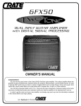
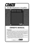
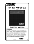
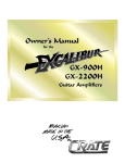
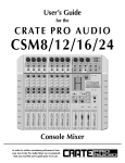
GT-500H
GUITAR AMPLIFIER
OWNER’S MANUAL
GT-500H Amplifier
Congratulations!
You are now the proud owner of one of the newest and most versatile tube amplifiers
available for the guitar, the GT-500H. This remarkable amplifier offers tremendous flexibility and power with two separate channels and silent switching for a uniquely rich palette of
tonal variety and simplicity of control over your sound.
Your GT-500H amplifier is musician-made in the U.S.A. using the finest components
available. Each unit is rigorously tested by skilled technicians and musicians to ensure that
your amplifier is the best it can be!
In order to get the most out of your new amplifier, we strongly urge you to go over the
information contained in this manual before you begin playing
And thank you for choosing
CAUTION
ATTENTION
VORSICHT
RISK OF ELECTRIC SHOCK
DO NOT OPEN
RISQUE D'ELECTROCUTION
NE PAS OUVRIR
ELEKTRISCHE SCHLAGGEFAHR
NICHT OFFENEN
CAUTION: TO REDUCE THE RISK OF ELECTRIC SHOCK,
DO NOT REMOVE COVER.
NO USER-SERVICEABLE PARTS INSIDE.
REFER SERVICING TO QUALIFIED SERVICE PERSONNEL.
ATTENTION: POUR REDUIRE D'ELECTROCUTION NE PAS
ENLEVER LE COUVERCLE. AUCUNE PIECE INTERNE N'EST REPRABLE
PAR L'UTILISATEUR. POUR TOUTE REPARATION, S'ADRESSER A UN
TECHNICIEN QUALIFIE.
VORSICHT: ZUR MINIMIERUNG ELEKTRISCHER SCHLAGGEFAHR NICHT
DEN DECKEL ABENHMEN. INTERNE TEILE KONNEN NICHT VOM
BENUTZER GEWARTET WERDEN. DIE WARTUNG IS QUALIFIZIERTEM
WARTUNGSPERSONAL ZU UBERLASSEN.
THIS EQUIPMENT HAS BEEN DESIGNED AND ENGINEERED TO PROVIDE SAFE AND RELIABLE OPERATION. IN ORDER TO PROLONG THE LIFE
OF THE UNIT AND PREVENT ACCIDENTAL DAMAGES OR INJURY, PLEASE FOLLOW THESE PRECAUTIONARY GUIDELINES:
CAUTION: TO REDUCE THE RISK OF ELECTRIC SHOCK, DO NOT OPEN CHASSIS; DO NOT DEFEAT OR REMOVE THE GROUND PIN OF THE
POWER CORD; CONNECT ONLY TO A PROPERLY GROUNDED AC POWER OUTLET.
WARNING: TO REDUCE THE RISK OF FIRE OR ELECTRIC SHOCK, DO NOT EXPOSE THIS EQUIPMENT TO RAIN OR MOISTURE.
CAUTION: NO USER-SERVICEABLE PARTS INSIDE. REFER SERVICING TO QUALIFIED SERVICE PERSONNEL.
CAUTION: THIS UNIT IS CAPABLE OF PRODUCING HIGH SOUND PRESSURE LEVELS. CONTINUED EXPOSURE TO HIGH SOUND PRESSURE
LEVELS CAN CAUSE PERMANENT HEARING IMPAIRMENT OR LOSS. USER CAUTION IS ADVISED, AND EAR PROTECTION RECOMMENDED IF
UNIT IS OPERATED AT HIGH VOLUME. THE CHART BELOW SHOWS THE U.S. GOVERNMENT’S OCCUPATIONAL SAFETY AND HEALTH ADMINISTRATION (OSHA) REGULATIONS WHICH WERE IN EFFECT AT THE TIME OF THIS PUBLICATION FOR PERMISSIBLE NOISE EXPOSURE, PER
29CFR1910.95, TABLE G-16:
SOUND LEVEL DBA, DURATION PER DAY
SLOW RESPONSE
IN HOURS
90
8
92
6
95
4
97
3
100
2
SOUND LEVEL DBA,
SLOW RESPONSE
102
105
110
115
DURATION PER DAY
IN HOURS
1 - 1 1/2
1
1/2
1/4 or less
ACCORDING TO OSHA, ANY EXPOSURE IN EXCESS TO THESE AMOUNTS LISTED ABOVE COULD RESULT IN SOME HEARING LOSS.
EXPLANATION OF
GRAPHICAL SYMBOLS:
2
"DANGEROUS VOLTAGE"
= "DANGER HAUTE TENSION"
"GEFAHLICHE SPANNUNG"
"IT IS NECESSARY FOR THE USER TO REFER TO THE INSTRUCTION MANUAL"
= "REFERREZ-VOUS AU MANUAL D'UTILISATION"
"UNBEDINGT IN DER BEDIENUNGSANLEITUNG NACHSCHLAGEN"
GT-500H Amplifier
TABLE OF CONTENTS:
Features . . . . . . . . . . . . . . . . . . . . . . . . . . . . . . . . . . .3
The Front Panel Controls and Their Use . . . . . . . . . . .4
The Rear Panel . . . . . . . . . . . . . . . . . . . . . . . . . . . . .5
Connecting to the Insert Jack . . . . . . . . . . . . . . . . . . .5
Some Suggested Settings . . . . . . . . . . . . . . . . . . . . .6
System Block Diagram . . . . . . . . . . . . . . . . . . . . . . . .7
Technical Specifications . . . . . . . . . . . . . . . .back cover
Features:
• All tube operation for classic vintage growl and howl, as you want it, when you want it
• Two completely independent channels with individual gain and tone controls
• Quick, silent channel switching from the front panel or with footswitch (provided)
• Individual reverb return controls for each channel
• Buffered insert jack – use a stereo-to-mono “Y” cord to patch in your favorite effect(s)
• Specially designed paper bobbin output transformer for a true “vintage” sound
• Drives 8 and 16 ohm speaker cabinets with no problem and delivers lots of true vintage
tone, tone, tone
• Durable tolex® covering and special cosmetic treatments for a unique stage appearance
3
GT-500H Amplifier
1
2
3
4
5
6
7
8
9
10
11
12
13
14
15
16
The Front Panel Controls and Their Use:
1. INPUT: This jack accepts a high impedance signal from a
guitar, bass, keyboard, etc.
9. CHANNEL B MID: This control adjusts the amount of
midrange frequency response on Channel B.
2. CHANNEL A VOLUME: This control sets the level of
Channel A. The sound is brighter at lower settings, and can
be cranked up for a crunchy rhythm sound.
10. CHANNEL B BASS: This control adjusts the level of low
frequency response on Channel B.
3. CHANNEL A TREBLE: This control adjusts the level of
high frequency response on Channel A.
4. CHANNEL A BASS: This control adjusts the level of low
frequency response on Channel A. (When playing at
extreme volume levels, you might want to back this control
down just a bit.)
5. CHANNEL SELECT: Silent channel switching is achieved
with this button. When the footswitch is plugged in, this button is deactivated.
6. INSERT JACK: This jack provides a line level access point
between the preamp and the power amp. The output is
buffered by a single transistor. It is out of the circuit completely when nothing is plugged into it. Use a Crate Model
#CYC6MS mono-to-stereo Y-cord, or a Y-adapter with
extenders. For more details refer to the section
“Connecting to the Insert Jack” on the following page.
7. CHANNEL B GAIN: Use this control to achieve sounds
ranging from bluesy crunch to full tilt-hard rock rhythm.
Experimenting with a combination of the gain and volume
controls on the amp along with your guitar’s volume controls can produce a wide variety of useable sounds.
8. CHANNEL B TREBLE: This control adjusts the level of the
high frequency response on Channel B.
4
11. CHANNEL B LEVEL: The overall volume level of
Channel B is controlled with this knob. When set at 2
o’clock, the power amp begins to be overdriven for true
power amp distortion.
12. CHANNEL A REVERB LEVEL: This control adjusts the
amount of reverb on Channel A.
13. CHANNEL B REVERB LEVEL: This control adjusts the
amount of reverb on Channel B.
14. FOOTSWITCH JACK: Use the supplied single-button
footswitch (Crate model #CFP-1) or an equivalent to
achieve silent remote channel switching. Plugging in the
footswitch deactivates the front panel channel switch (#5).
15. STANDBY SWITCH: This switch should remain turned off
when the unit is first turned on in order to allow the tubes
to warm up properly before high voltage is applied to
them. The Standby switch should also be turned off during extended breaks in playing when the amp is left on.
This will help ensure longer tube life.
16. POWER SWITCH: This switch applies power to the unit
when switched to the on (up) position.
The Standby and Power switches light up when on.
GT-500H Amplifier
Connecting to the Insert Jack:
SPEAKERS
50 WATTS RMS
47-269-04
SPEAKER
IMPEDANCE
Made in the
U.S.A. by
SLM ELECTRONICS
1400 Ferguson Ave.
St. Louis, MO 63133
8
16
EXT.
MAIN
(USE FIRST)
MODEL: GT-500H
18
The front panel Insert jack (#6) lets you patch external
effects into the GT-500H just prior to its power amp stage.
When using Crate’s CYC6MS stereo-to-mono Y-cord, connect
its 1/4” stereo plug into the amp’s Insert jack, its “send” plug
into the IN jack of the effect and its “return” plug into the OUT
jack of the effect.
Another method is to buy or make a stereo-to-mono Yadapter (such as Crate’s CA11Y) and use two 1/4” signal
cables to patch into the effect as shown below.
19
To Insert Jack
The Rear Panel:
17. AC LINE CORD (not shown): Connect the male end of this
heavy duty power cord to a properly grounded AC power
outlet of the correct voltage. DO NOT attempt to defeat the
ground pin of the power cord! (If your amplifier was purchased outside the United States, see the rear panel serial
number label for voltage and current information.)
TIP = RETURN
RING = SEND
SLEEVE = GROUND
18. IMPEDANCE SWITCH: For the best performance and
least strain on the amp, you MUST match the amp’s
impedance to that of your speaker cabinet(s). Set the
selector switch to the 8 or 16 ohm position, depending on
the total impedance of your cabinets. The chart below can
help you determine that impedance based on the following combinations of speakers connected in parallel.
CAB IMP.
16 ohms
32 ohms
32 ohms
# OF CABS
2
2
4
TOTAL IMP.
8 ohms
16 ohms
8 ohms
TIP
RING
SLEEVE
TIP (return):
Connect to OUT
jack of effect
RING (send):
Connect to IN
jack of effect
19. SPEAKER JACKS: Connect the amplifier to your speaker cabinet(s) via these jacks, using heavy-duty speaker
cables (not instrument patch cords). Use cabinets rated at
8 ohms or higher, in combinations which never create a
load lower than 8 ohms. Make sure the Impedance switch
(#18) is properly set. Always use the MAIN speaker jack
first, then connect to the EXTENSION jack if using more
than one cabinet.
OUT
IN
5
GT-500H Amplifier
Some Suggested Settings:
SPARKLING CLEAN
CRUNCH RHYTHM
WARM & CLEAN
BLUESY GRIND
BLUESY DIRT
"DRIVE 'EM MAD" SHRED
TRY THESE AT MIDNIGHT!
6
GT-500H Amplifier
System Block Diagram:
SECOND
GAIN
CHANNEL A:
CHANNEL A
TONES & VOLUME
INPUT
FIRST
GAIN
VOL. TREB. BASS
CHANNEL B:
TONE PREEMPHASIS
SECOND
GAIN
GAIN
THIRD
GAIN
CHANNEL B
TONES & LEVEL
FOURTH
& FIFTH
GAIN STAGE
TREB. MID
BASS LEVEL
FOOTSWITCH
REVERB
REVERB
LEVELS
INSERT
MAIN
SPEAKER
PHASE
SPLITTER
POWER
AMP
EXTENSION
SPEAKER
7
GT-500H Amplifier
TECHNICAL SPECIFICATIONS:
Output Power Rating
50W RMS @ 10% THD, 8 ohm load, 120 VAC
Input Impedance
1M ohm
Maximum Signal Accepted
2.8V peak to peak
Signal To Noise Ratio
Channel B:
Channel A:
52dB
58dB
Gain
Channel B:
Channel A:
75dB
68dB
Tone Control Range
Channel B:
Bass:
Mid:
Treble:
Bass:
Treble:
Channel A:
12dB, 60Hz
10dB, 600Hz
7dB, 4kHz
20dB, 70Hz
16dB, 2kHz
Line Out Level
375mV RMS @ full power output
Tube Type
Preamp: (4) 12AX7 Power Amp: (4) EL84/6BQ5
Power Requirements
120VAC, 60Hz, 110VA
100/115VAC, 50/60Hz, 110VA
230VAC, 50/60Hz, 110VA
Size and Weight
11”H x 21.25”W x 11.25”D, 35 lbs.
The GT-500H is covered with a durable black Tolex® material. To keep the cabinet in top condition,
wipe it clean with a damp lint-free cloth to remove dirt and road film. Never spray cleaning agents
directly onto the cabinet, and stay away from abrasive cleansers which could damage the finish.
Crate continually develops new products, as well as improves existing ones.
For this reason, the specifications and information in this publication
are subject to change without notice.
©1998 SLM ELECTRONICS • A division of St. Louis Music • 1400 Ferguson Avenue • St. Louis, Mo 63133
P/N 47-547-12 • 02/98