1
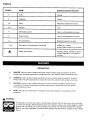
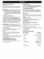
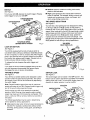
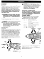
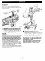
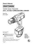
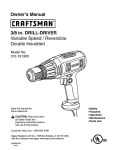
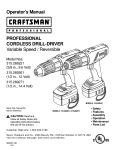
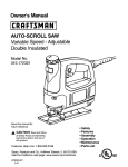
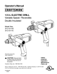
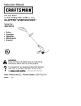
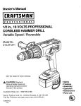
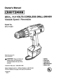
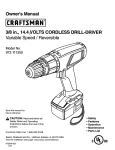
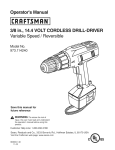
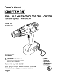
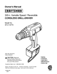
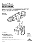
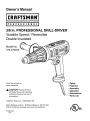
Owner's Manual
I P ,R
O
F
E" S
S
I
O N
A 'L
i
3/8 in. PROFESSIONAL
DRILL-DRIVER
Variable Speed / Reversible
Double Insulated
Model No.
315.279940
Save this manual
future reference
for
_, CAUTION: Read and follow
all Safety Rules and Operating
Instructions before first use of
this product.
Customer
Safety
Features
Assembly
Operation
Maintenance
Parts List
Help Line: 1-800-932-3188
Sears Roebuck and Co., Hoffman Estates, IL 60179 USA
Visit the Craftsman web page: www.sears.com/craftsman
972000-826
3-01
•
•
•
•
•
•
0®0s
•
Table of Contents ........................................................................................................................................................
•
General Safety Rules ..............................................................................................................................................
2-3
•
Specific Safety RulesAnd/Or
4-5
•
Features ..................................................................................................................................................................
•
Assembly ....................................................................................................................................................................
•
Operation ................................................................................................................................................................
•
Maintenance
.............................................................................................................................................................
12
•
Accessories
..............................................................................................................................................................
13
•
Exploded ViewAnd
•
Parts Ordering / Service ...........................................................................................................................................
,_
Symbols ....................................................................................................................
Repair Parts List .......................................................................................................................
INSTRUCTIONS
Work Area
•
7
8-11
15
16
When operating a power tool outside, use an
outdoor extension cord marked "W-A" or "W".
These cords are rated for outdoor use and reduce the
risk of electric shock.
Keep your work area clean and well lit. Cluttered
benches and dark areas invite accidents.
Do not operate power tools in explosive atmospheres, such as in the presence of flammable
liquids, gases, or dust. Power tools may create
sparks which may ignite the dust or fumes.
Personal
•
Keep bystanders, children, and visitors away while
operating a power tool. Distractions can cause you to
lose control.
Safety
Stay alert, watch what you are doing and use
common sense when operating a power tool. Do
not use tool while tired or under the influence of
drugs, alcohol, or medication. A moment of inattention while operating power tools may result in serious
personal injury.
Electrical Safety
•
5-7
Do not abuse the cord. Never use the cord to carry
the tools or pull the plug from an outlet. Keep cord
away from heat, oil, sharp edges, or moving pads.
Replace damaged cords immediately. Damaged
cords increase the risk of electric shock.
WARNING: Read and follow all instructions.
Failure to follow all instructions listed below, may result
in electric shock, fire and/or serious personal injury.
SAVE THESE
2
Double insulated tools are equipped with a polarized plug (one blade is wider than the other). This
plug will fit in a polarized outlet only one way. If the
plug does not fit fully in the outlet, reverse the
plug. If it still does not fit, contact a qualified
electrician to install a polarized outlet. Do not
change the plug in any way. Double insulation []
eliminates the need for the three-wire grounded power
cord and grounded power supply system.
•
Dress properly. Do not wear loose clothing or
jewelry. Contain long hair. Keep your hair, clothing,
and gloves away from moving parts. Loose clothes,
jewelry, or long hair can be caught in moving parts.
•
Avoid accidental starting. Be sure switch is off
before plugging in. Carrying tools with your finger on
the switch or plugging in tools that have the switch on,
invites accidents.
Remove adjusting keys or wrenches before turning
the tool on. A wrench or a key that is left attached to a
rotating part of the tool may result in personal injury.
Avoid body contact with grounded surfaces, such
as pipes, radiators, ranges, and refrigerators. There
is an increased risk of electric shock if your body is
grounded.
Do not overreach. Keep proper footing and balance
at all times. Proper footing and balance enables better
control of the tool in unexpected situations.
Don't expose power tools to rain or wet conditions.
Water entering a power tool will increase the risk of
electric shock.
Use safety equipment. Always wear eye protection.
Dust mask, nonskid safety shoes, hard hat, or hearing
protection must be used for appropriate conditions.
2
Tool Use and Care
•
Check for misalignment or binding of moving parts,
breakage of parts, and any other condition that
may affect the tool's operation. If damaged, have
the tool serviced before using. Many accidents are
caused by poorly maintained tools.
•
Use only accessories that are recommended by the
manufacturer for your model. Accessories that may
be suitable for one tool, may become hazardous when
used on another tool.
Use clamps or another practical way to secure and
support the workpiece to a stable platform. Holding
the work by hand or against your body is unstable and
may lead to loss of control.
•
Do not force tool. Use the correct tool for your
application. The correct tool will do the job better and
safer at the rate for which it is designed.
•
Do not use tool if switch does not turn it on or off.
Any tool that cannot be controlled with the switch is
dangerous and must be repaired.
Service
•
Disconnect the plug from power source before
making any adjustments, changing accessories,
storing the tool. Such preventive safety measures
reduce the risk of starting the tool accidentally.
Store idle tools out of the reach of children and
Tool service must be performed only by qualified
repair personnel. Service or maintenance performed
by unqualified personnel could result in a risk of injury.
•
When servicing a tool, use only identical replacement parts. Follow instructions in the Maintenance
section of this manual. Use of unauthorized parts or
failure to follow Maintenance Instructions may create a
risk of electric shock or injury.
•
•
or
other untrained persons. Tools are dangerous in the
hands of untrained users.
•
Maintain tools with care. Keep cutting tools sharp
and clean. Properly maintained tools with sharp cutting
edges are less likely to bind and are easier to control.
3
Holdtool by insulatedgrippingsurfaceswhenperformingan operationwherethe cuttingtool maycontact
hiddenwiringor its cord.Contact with a "live" wire will make exposed metal parts of the tool "live" and shock the
operator.
Additional
Rules For Safe Operation
Know your power tool. Read operator's manual
carefully. Learn its applications and limitations, as
well as the specific potential hazards related to this
tool. Following this rule will reduce the risk of electric
shock, fire, or serious injury.
Always wear safety glasses. Everyday eyeglasses
have only impact-resistant lenses; they are NOT
safety glasses. Following this rule will reduce the risk
of serious personal injury.
Protect your lungs. Wear a face or dust mask if the
operation is dusty. Following this rule will reduce the
risk of serious personal injury,
Make sure your extension cord is in good condition. When using an extension cord, be sure to use
one heavy enough to carry the current your product will draw. Awire gage size (A.W.G.) of at least
16 is recommended for an extension cord 100 feet
or less in length. A cord exceeding 100 feet is not
recommended. If in doubt, use the next heavier
gage. The smaller the gage number, the heavier the
cord. An undersized cord will cause a drop in line
voltage resulting in loss of power and overheating.
Inspect for and remove all nails from lumber before
drilling. Following this rule will reduce the risk of
serious personal injury.
Protect your hearing. Wear hearing protection
during extended periods of operation. Following this
rule will reduce the risk of serious personal injury.
Drugs, alcohol, medication. Do not operate tool
while under the influence of drugs, alcohol, or any
medication. Following this rule will reduce the risk of
electric shock, fire, or serious personal injury.
Inspect tool cords periodically and, if damaged,
have repaired at your nearest Factory Service
Center or other Authorized Service Organization.
Constantly stay aware of cord location. Following
this rule will reduce the risk of electric shock or fire.
Save these instructions. Refer to them frequently
and use them to instruct others who may use this
tool. If you loan someone this tool, loan them these
instructions also.
Check damaged parts. Before further use of the
tool, a guard or other part that is damaged should
be carefully checked to determine that it will
operate properly and perform its intended function.
Check for alignment of moving parts, binding of
moving parts, breakage of parts, mounting, and
any other conditions that may affect its operation.
A guard or other part that is damaged should be
properly repaired or replaced by an authorized
service center. Following this rule will reduce the risk
of shock, fire, or serious injury.
Do not abuse cord. Never carry the tool by the cord
or yank it to disconnect it from the receptacle.
Keep cord away from heat, oil, and sharp edges.
Following this rule will reduce the risk of electric shock
or fire.
,_WARNING:
Some dust created by power sanding,
sawing, grinding, drilling, and other construction
activities contains chemicals known to cause cancer,
birth defects or other reproductive harm. Some
examples of these chemicals are:
• lead from lead-based
paints,
• crystalline silica from bricks and cement
and other masonry products, and
• arsenic and chromium from chemicallytreated lumber.
Your risk from these exposures varies, depending on
how often you do this type of work. To reduce your
exposure to these chemicals: work in a well
ventilated area, and work with approved safety
equipment, such as those dust masks that are
specially designed to filter out microscopic particles.
SYMBOLS
SYMBOL
NAME
DESIGNATION/EXPLANATION
V
Volts
Voltage
A
Amperes
Current
Hz
Hertz
Frequency (cycles per second)
min
Minutes
Time
Alternating Current
Type or a characteristic of current
--_
Direct Current
Type or a characteristic
no
No Load Speed
Rotational speed, at no load
.../min
Revolutions or Reciprocation
Per Minute
Revolutions,
of current
strokes,
surface speed, orbits etc. per minute
_1=
Safety Alert Symbol
Indicates danger, warning or caution.
It means attention!!! Your safety is
involved.
DEFINITIONS
,_
A)
DANGER: Failure to obey a safety warning will result in serious injury to yourself or to others.
Always follow the safety precautions to reduce the risk of fire, electric shock and personal injury.
B)
WARNING: Failure to obey a safety warning can result in serious injury to yourself or to others.
Always follow the safety precautions to reduce the risk of fire, electric shock and personal injury.
C)
CAUTION: Failure to obey a safety warning may result in property damage or personal injury
to yourself or to others. Always follow the safety precautions to reduce the risk of fire, electric
shock and personal injury.
D)
NOTE: Advises you of information or instructions vital to the operation or maintenance of the
equipment.
WARNING:
The operation of any drill can result in foreign objects being thrown into your eyes, which can result
in severe eye damage. Before beginning power tool operation, always wear safety goggles or safety
glasses with side shields and a full face shield when needed. We recommend Wide Vision Safety
Mask for use over eyeglasses or standard safety glasses with side shields, available at Sears Retail
Stores.
KNOW
YOUR DRILL-DRIVER
VARIABLE
See Figure 1.
This tool has a variable speed switch that delivers higher
speed with increased trigger pressure. Speed is controlled
by the amount of switch trigger depression,
Before attempting to operate your drill-driver, familiarize
yourself with all operating features and safety requirements.
,_
TWO SPEED
speed.
BIT STORAGE
When not in use, bits provided with your drill-driver can be
placed in the storage area located on the top of the motor
housing.
CONNECTION
Your drill-driver has a precision built electric motor. It
should be connected to a power supply that is 120
volts, 60 Hz, AC only (normal household current). Do
not operate this tool on direct current (DC). A substantial
voltage drop will cause a loss of power and the motor will
overheat. If your drill-driver does not operate when
plugged into an outlet, double-check the power supply.
_,
AUXILIARY
APPLICATIONS
(Use only
CHUCK
Your drill-driver has a keyless chuck that allows you to hand
tighten or release drill bit in the chuck jaws.
SWITCH
for the purpose
Drilling in wood,
Drilling in ceramics, plastics, fiberglass, and laminates.
•
Drilling in both hard and soft metals.
•
Using driving accessories,
screwdriver bits.
•
Mixing paints.
The switch trigger can be locked in the OFF position. This
feature helps reduce the possibility of accidental starting
tool when not in use.
Rating
FORWARD/REVERSE
Gear Train
(DIRECTION
Input
SELECTOR
OF ROTATION SELECTOR)
Your drill-driver has a forward/reverse
such as driving screws with
SPECIFICATIONS:
Chuck Capacity
LOCK
below)
•
DRILL-DRIVER
Release switch trigger to turn your drill-driver OFF.
listed
•
PRODUCT
To turn your drill-driver ON, depress the switch trigger.
SWITCH
HANDLE
An auxiliary handle is packed with your drill-driver for ease
of operation and to help prevent loss of control,
WARNING: Do not allow familiarity with your drilldriver to make you careless. Remember that a careless
fraction of a second is sufficient to inflict severe injury.
KEYLESS
GEAR TRAIN
Your drill-driver has a two speed gear train designed for
drilling or driving at HI or LO speeds. A slide switch is
located on top of your drill-driver to select either HI or LO
WARNING: Carefully read through this entire owner's
manual before using your new drill-driver. Pay close
attention to the Rules For Safe Operation, Warnings
and Cautions. If you use your drill-driver properly and
only for what it is intended, you will enjoy years of safe,
reliable service.
ELECTRICAL
SPEED
Switch
315.279940
1/16 in. to 3/8 in.
120 V, 60 Hz, AC only
5.5 Amperes
Two Speed
Variable Speed
selector located
No Load Speed
above the switch trigger.
0-400 RPM (Low)
0-1400 RPM (High)
Clutch
Maximum Torque
6
24 Positions
668 in./Ibs.
TWO SPEED
GEARTRAIN(HI-LO)
BIT STORAGEAREA
AUXILIARY
HANDLE
DIRECTIONOF
ROTATIONSELECTOR
(FORWARD/REVERSE)
KEYLESS
CHUCK
TORQUE
ADJUSTMENT
RING
SWITCH
TRIGGER
LOCK-ON
BuIrON
SCREWDRIVERBITS_
Fig. 1
,_
WINGSCREW
WARNING: If any parts are missing, do not operate
your drill-driver until the missing parts are replaced.
Failure to do so could result in possible serious
personal injury.
AUXILIARY
TO LOOSEN
TORQUE
ADJUSTMENT
RING
AUXlLIAR_
HANDLE
See Figure 2.
OI_TIGHTEN
HANDLE
GROOVE
An auxiliary handle is packed with your drill-driver for ease of
operation and to help prevent loss of control. The handle can
be rotated 360 °.
Note: For convenience and ease of starting threads, the
hex nut has been trapped inside the molded slot in the
auxiliary handle.
NOTCHES
TO INSTALL:
•
_1
•
•
•
•
360°
ROTATION
Unplug your drill-driver.
WARNING: Failure to unplug your drill-driver could
result in accidental starting causing serious injury.
Place ring of handle over the chuck and torque
adjustment ring. Note: Notches in handle fits in a
groove behind torque adjustment ring.
Once in position behind torque adjustment ring, rotate
handle to desired angle.
Thread wing screw into handle insert.
Tighten wing screw securely.
7
RAISEDRIB
Fig. 2
SWITCH
•
Medium speed is suitable for drilling hard metals,
plastics, and laminates.
•
High speed produces best results when maximum
power is required. For example, drilling in wood; soft
metals such as aluminum, brass, and copper, and
when using driving accessories.
See Figure 3.
To turn your drill ON, depress the switch trigger. Release
switch trigger to turn your drill OFF.
FORWARD/REVERSE
SELECTOR
TWO
CENTERPOSITION
(LOCK)
SWITCH
TRIGGER
LOCK-ON
BUTTON
TO INCREASESPEED,
DEPRESSSWITCHTRIGGER
LOCK-ON
SPEED
GEAR TRAIN
See Figure 4.
Your drill has a two-speed gear train designed for drilling
or driving at LO (1) or HI (2) speeds. A slide switch is
located on top of your drill to select either LO (1) or HI (2)
speed. When using drill in the LO (1) speed range, speed
will decrease and unit will have more power and torque.
When using drill in the HI (2) speed range, speed will
increase and unit will have less power and torque. Use
LO (1) speed for high power and torque applications and
HI (2) speed for fast drilling or driving applications.
TWO SPEED
GEARTRAIN(HI-LO}
Fig. 3
BUTTON
See Figure 3.
LO
SPEED
HI
Your drill is equipped with a lock-on feature which is
convenient when continuous drilling for extended periods
of time is required. To lock-on, depress the switch trigger,
push in and hold the lock-on button located on the side of
the handle, then release switch trigger. Release lock-on
button and your drill will continue running.
To release the lock, depress the switch trigger and
release.
If you have the lock-on feature engaged during use and
your drill becomes disconnected from power supply,
disengage the lock-on feature immediately.
VARIABLE
SPEED
Fig. 4
SWITCH
LOCK
See Figure 3.
See Figure 5.
Your drill has a variable speed switch designed to allow
operator control of speed and torque limits. The speed
and torque of your drill can be increased by depressing
the switch trigger.
The switch trigger can be locked in the OFF position. This
feature can be used to prevent the possibility of accidental
starting when not in use. To lock switch trigger, place the
direction of rotation selector in center position.
Note: Depress switch trigger all the way for maximum .
speed and torque of your drill. Depress switch trigger only
part of the way for less speed and torque.
Avoid running your drill at low speeds for extended
periods of time. Running at low speeds under constant
usage may cause your drill to become overheated. If this
occurs, cool your drill by running it without a load and at
full speed.
SELECTOR
CENTERPOSITION
REVERSE
(LOCK)
The following guidelines may be used in determining
correct speed for various applications:
•
Low speed is ideal when minimum speed and power is
required. For example, starting holes without center
punching, driving screws, mixing paint, and drilling in
ceramics.
FORWARD
Fig. 5
REVERSIBLE
See Figure 5.
This tool has the feature of being reversible. The direction
of rotation is controlled by a selector located above the
switch trigger. With the drill held in normal operating
position, the direction of rotation selector should be
positioned to the left of the switch for drilling. The drilling
direction is reversed when the selector is to the right of
the switch. When the selector is in center position, the
switch trigger is locked.
_i
CAUTION: To prevent gear damage, always allow
chuck to come to a complete stop before changing
the direction of rotation or the two speed gear train
(hi-lo).
To stop, release switch trigger and allow the chuck to
come to a complete stop.
_lb WARNING: Your drill should never be connected to
power supply when you are assembling parts,
making adjustments, installing or removing drill bits,
cleaning, or when not in use. Disconnecting your drill
will prevent accidental starting that could cause
serious personal injury.
KEYLESS
CHUCK
See Figure 6.
A keyless chuck has been provided with your drill to allow
for easy installation and removal of bits. As the name
implies, you can hand tighten or release drill bits in the
chuck jaws. Arrows on the chuck indicate which direction
to rotate the chuck sleeve in order to LOCK (tighten) or
UNLOCK (release) the chuck jaws. Loosen the chuck
sleeve by rotating it counterclockwise with one hand.
Insert drill bit straight into the chuck the full length of the
jaws, and tighten securely by rotating the chuck sleeve in
clockwise direction.
_IL WARNING:
Do not hold chuck sleeve with one
hand and use power of the drill to tighten chuck jaws
on drill bit. Chuck sleeve could slip in your hand or
your hand could slip and come in contact with
rotating drill bit. This could cause an accident
resulting in serious personal injury.
ADJUSTABLE
TORQUE
CLUTCH
Your drill is equipped with an adjustable torque clutch for
driving different types of screws into different materials.
The proper setting depends on the type of material and
the size of screw you are using.
TO ADJUST
TORQUE
•
Identify the twenty four torque indicator settings
located on the front of your drill. See Figure 7.
•
Rotate adjusting ring to the desired setting.
1 -
4
For driving small screws.
•
5 -
8
For driving screws into soft
material.
•
9 - 12
For driving screws into soft and
hard materials.
• 13 - 16
For driving screws in hard wood.
• 17 - 20
For driving large screws.
• 21 - ,11
For heavy drilling.
TO DECREASE
TORQUE
ADJUSTING
RING
UNLOCK
(Release)
JAWS
CHUCK
,_
T01NCREASE
TORQUE
Fig. 7
Note: Remember the two-speed feature (HI-LO) when
setting torque. The amount of torque will vary depending
on which speed setting you have your drill-driver.
Switching to LO speed will increase torque. Switching to
HI speed will decrease torque.
DRILLBIT
LOCK
(Tighten)
CHUCKSLEEVE
Fig. 6
BIT STORAGE
See Figure 8.
When not in use, bits provided with your drill can be
placed in the storage area located on the top of your drill
as shown in figure 8.
BIT
AREA
STORAGE
SCREWDRIVER
BITS
Fig. 8
,_
WARNING:
Always wear safety goggles or safety
glasses with side shields when operating your drill.
Failure to do so could result in dust, shavings, loose
particles or foreign objects being thrown into your
eyes, causing possible serious injury.
Fig. 9
_k
DRILLING
See Figure 9.
When drilling hard smooth surfaces.use a center punch to
mark desired hole location. This will prevent the drill bit
from slipping off center as the hole is started. However,
the low speed feature allows starting holes without center
punching if desired. To accomplish this, simply operate
your drill at a low speed until the hole is started.
The material to be drilled should be secured in a vise or
with clamps to keep it from turning as the drill bit rotates.
WARNING:
Be prepared for binding or bit
breakthrough. When these situations occur, drill has
a tendency to grab and kick opposite to the direction
of rotation and could cause loss of control when
breaking through material. If not prepared, this loss
of control can result in possible serious injury.
When drilling metals, use a light oil on the drill bit to keep
it from overheating. The oil will prolong the life of the bit
and increase the drilling action.
If the bit jams in workpiece or if the drill stalls, release
switch trigger immediately. Remove the bit from the
workpiece and determine the reason for jamming.
Hold tool firmly and place the bit at the point to be drilled.
Depress the switch trigger to start tool.
Move the drill bit into the workpiece applying only enough
pressure to keep the bit cutting. Do not force or apply side
pressure to elongate a hole.
10
CHUCK
REMOVAL
•
Insert hex key wrench into chuck and tighten chuck
jaws securely. Tap sharply with a mallet in a
counterclockwise direction. This will loosen the chuck
on the spindle. It can now be unscrewed by hand.
See Figure 12.
See Figure 10, 11, and 12.
The chuck must be removed in order to use some
accessories. To remove:
•
Unplug your drill.
,_i
WARNING: Failure to unplug your drill could result in
accidental starting causing serious injury.
•
Place two speed gear train in the low setting and rotate
torque adjusting ring to the maximum torque setting.
•
Insert a 8 mm (5/16 in.) or larger hex key wrench into
the chuck of your drill and tighten the chuck jaws
securely.
•
Tap the hex key wrench sharply with a mallet in a
clockwise direction. See Figure 10.
•
This will loosen the screw in the chuck for easy
removal.
MALLET
TORQUE
ADJUSTING
RING
TWO SPEED
GEAR TRAIN(HI-LO)
Fig. 12
TO RETIGHTEN
A LOOSE
CHUCK
The chuck may become loose on the spindle and develop
a wobble.
CHUCK
JAWS
To tighten, follow these steps:
•
,_
HEX KEYWRENCH
•
WARNING: Failure to unplug your drill could result in
accidental starting causing serious; injury.
•
Open the chuck jaws.
•
Insert hex key wrench into chuck and tighten chuck
jaws securely. Tap hex key wrench sharply with a
mallet in a clockwise direction. This will tighten the
chuck on the spindle.
•
Open the chuck jaws and remove the hex key
wrench.
•
Tighten the chuck screw.
Fig. 10
Open the chuck jaws and remove hex key wrench.
Remove the chuck screw by turning it in a clockwise
direction. See Figure 11.
Unplug your drill.
Note: The chuck screw has left hand threads.
Note: The chuck screw has left hand threads.
SCREWDRIVER
Fig. 11
11
I 1]=1
GENERAL
DOUBLEINSULATION
All parts represent an important part of the double
insulation system and should be serviced only at a Sears
Service Center.
Double insulation is a concept in safety in electric power
tools, which eliminates the need for the usual three-wire
grounded power cord. All exposed metal parts are
isolated from the internal metal motor components with
protecting insulation. Double insulated tools do not need
to be grounded.
Avoid using solvents when cleaning plastic pads. Most
plastics are susceptible to damage from various types of
commercial solvents and may be damaged by their use.
Use clean cloths to remove dirt, carbon dust, etc.
,_
IMPORTANT
Servicing of a tool with double insulation requires extreme
care and knowledge of the system and should be
performed only by a qualified service technician. For
service, we suggest you return the tool to your nearest
Sears Service Center for repair. Always use original
factory replacement parts when servicing.
WARNING: Do not at any time let brake fluids,
gasoline, petroleum-based products, penetrating oils,
etc. come in contact with plastic pads. They contain
chemicals that can damage, weaken or destroy
plastic.
EXTENSION
It has been found that electric tools are subject to
accelerated wear and possible premature failure when
they are used on fiberglass boats, sports cars, wallboard,
spackling compounds, or plaster. The chips and grindings
frem these materials are highly abrasive to electric tool
pads, such as bearings, brushes, commutators, etc.
Consequently, it is not recommended that this toot be
used for extended work on any fiberglass material,
wallboard, spackling compounds, or piaster. During any
use on these materials, it is extremely important that the
tool is cleaned frequently by blowing with an air jet.
The use of any extension cord will cause some loss of
power. To keep the loss to a minimum and to prevent tool
overheating, use an extension cord that is heavy enough
to carry the current the tool will draw.
A wire gage size (A.W.G.) of at least 16 is recommended
for an extension cord 100 feet or less in length. When
working outdoors, use an extension cord that is suitable
for outdoor use. The cord's jacket will be marked WA.
,_IL CAUTION:
Keep extension cords away from the
drilling area and position the cord so that it will not get
LUBRICATION
caught on lumber, tools, etc., during drilling operation.
All of the bearings in this tool are lubricated with a sufficient amount of high-grade lubricant for the life of the unit
under normal operating conditions. Therefore, no further
lubrication is required.
,_
CORDS
_ll
WARNING: Always wear safety goggles or safety
glasses with side shields during power tool operation
or when blowing dust. If operation is dusty, also wear
a dust mask.
WARNING:
Check extension cords before each use.
If damaged replace immediately. Never use tool with
a damaged cord since touching the damaged area
could cause electrical shock resulting in serious injury.
Extension cords suitable for use with your drill are
available at your nearest Sears Retail Store.
12
Thefollowingrecommended
accessories
arecurrentlyavailableatSearsretailstores.
•
•
•
•
HighSpeedBits(Forwoodor metal).........1/2in.Max. •
MasonryBits...............................................
3/4in.Max. •
WoodBoringBits...........................................
1 in.Max. •
HoleSaws.....................................................
2 in.Max.
WARNING:
Doweling
Jig (ItemNo.9-4186)
Drill Stand (Item No. _-25989)
Wire Brushes, All
The use of attachments or accessories not listed might be hazardous.
WARRANTY
FULL ONE YEAR WARRANTY
ON CRAFTSMAN
PROFESSIONAL
DRILL-DRIVER
If this tRAFT$MRN
Drill-Driver fails due to a defect in material or workmanship within one year from the date of purchase, Sears will repair it, free of charge.
WARRANTY SERVICE IS AVAILABLE BY SIMPLY RETURNING THE TOOL TO THE NEAREST SEARS STORE OR
SEARS SERVICE CENTER IN THE UNITED STATES.
This warranty gives you specific legal rights, and you may also have other rights which vary from state to state.
Sears, Roebuck and Co., Dept. 817WA, Hoffman Estates, IL 60179
SAVE THESE INSTRUCTIONS
13
14
CRAFTSMAN
I
318 in. PROFESSIONAL
DRILL-DRIVER
MODEL NO. 315.279440
The model number will be found on a plate attached to the motor housing. Always mention the model
number in all correspondence regarding your CRAFTSMAN 318 In. PROFESSIONAL DRILL-DRIVER or
when ordering parts.
SEE BACK PAGE FOR PARTS ORDERING
5
INSTRUCTIONS
SEE NOTE"A"
3
4
2
6
PARTS LIST
Key No.
Pad No.
1
616478-003
Screw (Special) ...................................................................................
1
2
981839-001
Auxiliary Handle ..................................................................................
1
3
981840-001
Wing Screw .........................................................................................
1
4
981502-001
3/8 in, Chuck (Item No, 9-20955) ........................................................
1
5
982508-001
Data Plate ...........................................................................................
1
6
982509-001
Logo Plate ...........................................................................................
1
7
982510-001
Carrying Case - Not Shown ...............................................................
Owner's Manual
1
972000-826
Description
Quart.
NOTE: "A"- The assembly shown represents an "tmportant part of the Double Insulated System. To avoid the
possibility of alteration or damage to the system, service should be performed by your nearest Sears Repair
Center. Contact your nearest Sears Retail Store for Service Center information.
15
I
Get it fixed, at your home or ours!
For repair of major brand appliances in your own home...
no matter who made it, no matter who sold ifl
1-800-4-MY-HOME
s_Anyt,me,
day or n,ght
(1-800-469-4663)
www.sears.com
To bring in products such as vacuums, lawn equipment and electronics
for repair, call for the location of your nearest Sears Parts & Repair Center.
1-800-488-1222
Anyt,me,
day or n,ght
www.sears.com
For the replacement parts, accessories and owner's manuals
that you need to do-it-yourself, call Sears PartsDirect sM!
1-800-366-PART
6 a m. -
(1-800-368-7278)
11 p.m. CST,
7 days a week
www.sears.com/partsdirect
To purchase
or inquire about a Sears Service Agreement:
1-800-827-6655
7 a.m - 5 p.m. CST, Mon. - Sat
Para pedlr servl¢_O de reparac_6n a domlclho,
y para ordenar plezas con entrega a domlclho'
1-888-SU-HOGAR
sM
Au Canada
pour service
(1-877-533-6937)
(1-888-784-6427)
SEARS
HomeCentral
® Registered Trademark
© Sears, Roebuck and Co
en franqals'
1-877-LE-FOYER s,_
TM
/ ru Trademark of Sears, Roebuck and CO
® Marca Reglstrada / TMMarca de Fabnca de Sears, Roebuck and Co