1
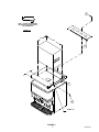
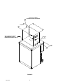
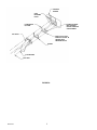
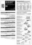
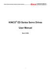
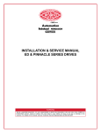
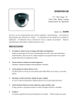
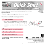
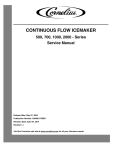
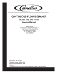
Cornelius Incorporated
500 Regency Drive
Glendale Heights, IL 60139
Telephone (630) 980-6900
Facsimile (630) 980-8511
ICEMAKER ADAPTER KIT (P/N 629085001)
This Icemaker Adapter Kit (P/N 629085001) is for the following Units:
Dispenser Model
Icemaker Model
ED200/250
Wilshire WCC500/700
Table 1. Adapter Kit Parts
Item
No.
Part No.
Name
Qty.
1
620032802
Icemaker Adapter Lid
1
2
22128
Bracket, Icemaker Mounting
2
3
50904
RTV, 3-Oz. Tube
1
4
620032804
Cover, Manual Ice Fill
1
5
70226
#10 Sheet Metal Screw
12
6
70188
Thumb Screw, #8--32X3/8--in. Long
1
7
620913501
Installation Instructions
1
CAUTION: Disconnect electrical power from the Dispenser before attempting to install this
Kit.
1. Remove merchandiser from the Dispenser by lifting up on both the right and the left sides to disengage the
merchandiser from slots in the Dispenser cabinet. Tilt the merchandiser forward from the top and lift off.
NOTE: Disregard step 2 if the ice diverter has been factory installed.
2. Refer to Figure 4 for the following:
A.
Remove the ice chute cover (snap-fit) and ice chute (4 nuts).
B.
Remove the gate restrictor and discard.
C.
Install the ice diverter as shown.
D.
Replace the ice chute and cover.
3. Refer to Figure 3 for adjusting the automatic agitation timer.
A.
Loosen/rotate the center mounting screw that secures the white reflector panel/electrical control box
cover in place and lower the cover to expose the automatic agitation timer.
B.
Adjust the timer to 2-seconds “ON”and 1-hour “OFF”as shown in Figure 3.
C. Reinstall the white reflector panel and the merchandiser.
E IMI Cornelius Inc; 1998
REV: A
October 27, 1998
620913501
NOTE: Disregard steps 4, 5, and 6 if the Dispenser has the icemaker adapter lid factory installed.
4. Remove the plastic ice storage hopper lid and discard.
5. Place the lid assembly supplied with the kit on top of the Dispenser and position it flush with the back and
sides of the Dispenser as shown in Figure 1.
6. Using the slotted holes in the lid as a template, drill four .136 diameter (#29 drill size) holes at the bottom of
the slots (see Figure 1, detail A) into the Dispenser cabinet. Use care not to drill into the ice storage hopper. Fasten the cover to the Dispenser with four #10 sheet metal screws, two on each side.
7. Seal the icemaker to the Dispenser lid as follows (see Figure 2):
A.
Run a bead of RTV around the opening in the lid and inside the perimeter of the icemaker outline so
that the icemaker will set on the RTV.
B.
Set the icemaker onto the lid and position it as shown in Figure 2.
C.
Wipe away any excessive RTV.
8. Install the icemaker mounting brackets (item 2) as shown in Figure 2. Using the brackets as a template,
drill .136 diameter (#29 drill size) holes into the icemaker cabinet and the Dispenser lid (item 1). Use care
not to drill into any icemaker components (condenser, tubing, etc.). Secure the brackets using the #10
sheet metal screws provided.
9. Follow the icemaker manufacturer’s instructions to complete the installation of the icemaker including the
bin thermostat.
10. Secure the manual ice fill cover in position on the lid over the rear hopper access opening with the thumb
screw (item 6). Note that the gasket should be compressed to form a seal against the icemaker cabinet
with the cover secured in position.
620913501
2
6
DRILL .136 DIA. HOLES USING
BOTTOM OF SLOTTED HOLES
AS A TEMPLATE.
DETAIL “A”
ENLARGED
14 1/2”
25”
4
7”
1
5
DETAIL ”A”
FIGURE 1.
3
620913501
FRONT OF ICEMAKER
FLUSH WITH SIDE OF DISPENSER
14 1/2”
25”
RUN A BEAD OF RTV INSIDE
THE PERIMETER OF THE
ICEMAKER OUTLINE ON THE LID
2
5
7”
FIGURE 2.
620913501
4
FIGURE 3.
5
620913501
STORAGE
HOPPER
GATE
MOUNTING
PLATE
FLANGE EXTENDS
INTO STORAGE
HOPPER THROUGH
GATE OPENING
ICE DIVERTER
P/N 15484
ICE CHUTE
APPLY RTV TO THIS
SURFACE TO SEAL TO
HOPPER GATE
MOUNTING PLATE
GASKET
FLAT WASHER
10--32 NUT
FIGURE 4.
620913501
6