1
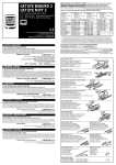
IMI CORNELIUS INC
One Cornelius Place
Anoka MN 55303--6234
Telephone (800) 238--3600
Facsimile (612) 422--3246
FOR
ED2XX DUAL-MOUNTING KIT
DISPENSER MODEL
KIT PART NUMBER
ED200/250
629085101
PARTS LIST
Item
No.
Part No.
Name
Qty.
1
629080214
Insulated Lower Panel, Dual
1
2
29677
Rear Mounting Plate
1
3
620023904
Front Mounting Plate (For 6 and 8 Beverage Valve Units)
1
4
32990
Wire Connectors
4
5
50904
RTV Sealant, 3--oz Tube
2
6
620013301
Drip Tray Cover, Black
1
7
620500201
Gasket
8
620914101
Installation Instructions
1
9
70555
Screw, No. 8-32 By 1 5/16-In. long
2
10
71010
Captivating Plastic Washer, No. 8
2
11
91486
Cornelius Logo
1
150-In
1. Disconnect electric power to the Ice/Beverage Units while installing the Kit.
2. Remove lower panel assembly from both Units.
3. Relocate beverage valve keyswitch to right side of the beverage panel on one of the Units. This Unit will be
positioned on the right side of the counter.
A.
Remove beverage panel access covers.
B.
Locate black and red wires of the keyswitch. Cut these wires approximately 2-inches from the crimp
nut connection to the yellow wires.
C.
Loosen the keyswitch mounting nut and remove the keyswitch. Using a 7/8-inch deep socket will help
access the nut.
D.
Remove plastic plug from right side of the beverage panel and insert into the left side keyswitch
opening.
E.
Install keyswitch into the right side of the beverage panel and tighten mounting nut.
E IMI Cornelius Inc; 1998
Rev A
December 9, 1998
620914101
F.
Move black and red wires from left to right side of the beverage panel. Strip red/black wires and
reconnect to the keyswitch using wire connectors (item 4) provided.
G.
Install beverage panel access covers.
4. Install Adaptor Kits if applicable for the type of ice makers used.
5. Apply self-adhesive gasket material (item 7) to the side of one Unit as indicated in Figure 1. Ends of the
gasket should fit tight to each other.
6. Place Units into position on the counter. The Units must be at the same height and sitting level. The
outside--outside dimension of the Units should be 60--3/8 inches (3/8--inch between the Units at the center).
7. Remove one screw from each base at the rear of the Unit and install rear mounting plate (item 2) to maintain the proper spacing between the Units (see Figure 2).
8. Install front mounting plate (item 3) using the four beverage panel mounting screws at the center of the
Units. The rectangular plate is for use with the six or eight valve Units.
9. Apply RTV (item 5) at the gasket-cabinet joint to seal any gaps between the Units, on all sides of the gasket.
10. Using one screw on each cabinet at the center of the Units (above the drip trays), install drip tray cover to
match color of the drip tray. The drip trays must be at the same height along the edges for cover to fit
properly.
11. Assemble two long #8--32 screws (item 9) to lower panel (item 1) using plastic washers (item 10). Install
lower panel assembly on Units.
12. Install Cornelius logo (item 11).
13. Replace hopper covers on the Units, manual fill Units.
14. Connect power cords for Ice/Beverage Dispenser to electrical outlet. Check Dispensers for proper operation.
620914101
2
APPLY GASKET
BETWEEN SIDES OF
KEYSWITCH
KEYSWITCH
11
3 FRONT MOUNTING PLATE
60 3/8
60 5/8
FIGURE 1.
AS REQ’D
REAR MOUNTING
PLATE
1
9
10
3 FRONT MOUNTING PLATE
6
SEAL WITH RTV
AS REQ,D
BEVERAGE PANEL
ACCESS COVER
KEYSWITCH
FIGURE 2.
3
620914101