1
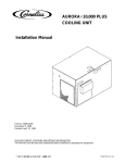
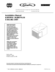
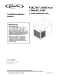
AURORAR10,000
COOLING UNIT
Installation Manual
Part No. 300381000
July 13, 1988
Revised: April 12, 1993
THIS DOCUMENT CONTAINS IMPORTANT INFORMATION
This Manual must be read and understood before installing or operating this equipment
Ó IMI CORNELIUS INC; 1988--93
PRINTED IN U.S.A
TABLE OF CONTENTS
Page
GENERAL INFORMATION . . . . . . . . . . . . . . . . . . . . . . . . . . . . . . . . . . . . . . . . . . . . . . . . . .
1
GENERAL DESCRIPTION . . . . . . . . . . . . . . . . . . . . . . . . . . . . . . . . . . . . . . . . . . . . . .
1
COOLING UNIT DESCRIPTION . . . . . . . . . . . . . . . . . . . . . . . . . . . . . . . . . . . . . . . . .
SYSTEM THEORY OF OPERATION . . . . . . . . . . . . . . . . . . . . . . . . . . . . . . . . . . . . .
INSTALLATION . . . . . . . . . . . . . . . . . . . . . . . . . . . . . . . . . . . . . . . . . . . . . . . . . . . . . . . . . . . .
1
3
5
UNPACKING AND INSPECTION . . . . . . . . . . . . . . . . . . . . . . . . . . . . . . . . . . . . . . . .
IDENTIFICATION OF LOOSE-SHIPPED PARTS . . . . . . . . . . . . . . . . . . . . . . . . . . .
SELECTING LOCATION . . . . . . . . . . . . . . . . . . . . . . . . . . . . . . . . . . . . . . . . . . . . . . . .
COOLING UNIT . . . . . . . . . . . . . . . . . . . . . . . . . . . . . . . . . . . . . . . . . . . . . . . . . . .
5
5
5
5
REMOTE CONDENSER COIL AND FAN ASS’Y . . . . . . . . . . . . . . . . . . . . . .
INSTALLING REMOTE CONDENSER COIL AND FAN ASS’Y . . . . . . . . . . . . . . .
INSTALLING COOLING UNIT . . . . . . . . . . . . . . . . . . . . . . . . . . . . . . . . . . . . . . . . . . .
PLACING COOLING UNIT IN LOCATION . . . . . . . . . . . . . . . . . . . . . . . . . . . .
CONNECTING REMOTE CONDENSER COIL AND FAN ASS’Y
REFRIGERATION LINES TO COOLING UNIT . . . . . . . . . . . . . . . . . . . . . . . .
6
6
6
6
CONNECTING ELECTRICAL POWER CIRCUIT TO COOLING UNIT . . . .
CONNECTING PLAIN WATER INLET SUPPLY LINE TO COOLING UNIT
CONNECTING CO2 INLET SUPPLY LINE TO COOLING UNIT . . . . . . . . .
CONNECTING SYRUP SOURCE LINES TO COOLING UNIT SYRUP
INLET LINES . . . . . . . . . . . . . . . . . . . . . . . . . . . . . . . . . . . . . . . . . . . . . . . . . . . . .
CONNECTING COOLING UNIT SYRUP OUTLET LINES TO INSULATED
PYTHON SYRUP LINES . . . . . . . . . . . . . . . . . . . . . . . . . . . . . . . . . . . . . . . . . . .
7
9
9
CONNECTING COOLING UNIT PLAIN WATER OUTLET LINE TO
INSULATED PYTHON PLAIN WATER LINE . . . . . . . . . . . . . . . . . . . . . . . . . . .
CONNECTING COOLING UNIT CARBONATED WATER OUTLET LINES TO
INSULATED PYTHON CARBONATED WATER LINES . . . . . . . . . . . . . . . . .
PLACING COOLING UNIT IN OPERATING POSITION . . . . . . . . . . . . . . . . . . . . .
PREPARING COOLING UNIT FOR OPERATION . . . . . . . . . . . . . . . . . . . . . .
7
9
10
10
10
10
11
OPERATION . . . . . . . . . . . . . . . . . . . . . . . . . . . . . . . . . . . . . . . . . . . . . . . . . . . . . .
STARTING COOLING UNIT REFRIGERATION SYSTEM . . . . . . . . . . . . . . .
STARTING CARBONATED WATER CIRCULATING PUMP . . . . . . . . . . . . .
ACTIVATING SYRUP SYSTEMS . . . . . . . . . . . . . . . . . . . . . . . . . . . . . . . . . . . .
LEAK CHECK AND INSULATING COOLING UNIT OUTLET LINES . . . . . .
DISPENSING STATION ADJUSTMENTS . . . . . . . . . . . . . . . . . . . . . . . . . . . . .
INSTALLING LINE IDENTIFICATION LABEL . . . . . . . . . . . . . . . . . . . . . . . . . .
11
12
12
12
13
13
13
OPERATORS INSTRUCTIONS . . . . . . . . . . . . . . . . . . . . . . . . . . . . . . . . . . . . . . . . . . . . . .
15
OPERATING CONTROLS . . . . . . . . . . . . . . . . . . . . . . . . . . . . . . . . . . . . . . . . . . . . . .
COOLING UNIT REFRIGERATION POWER SWITCH . . . . . . . . . . . . . . . . .
COOLING UNIT CARBONATOR MOTOR SWITCH . . . . . . . . . . . . . . . . . . . .
COOLING UNIT CIRCULATING MOTOR SWITCH . . . . . . . . . . . . . . . . . . . . .
REFRIGERATION SYSTEM TEMPERATURE SENSING DEVICE AND
HIGH-PRESSURE CUTOUT SWITCH . . . . . . . . . . . . . . . . . . . . . . . . . . . . . . .
15
15
15
15
DAILY PRE-OPERATION CHECK . . . . . . . . . . . . . . . . . . . . . . . . . . . . . . . . . . .
ADJUSTMENTS . . . . . . . . . . . . . . . . . . . . . . . . . . . . . . . . . . . . . . . . . . . . . . . . . . . . . . .
ADJUSTING CO2 REGULATORS . . . . . . . . . . . . . . . . . . . . . . . . . . . . . . . . . . .
16
16
16
i
15
300381000
TABLE OF CONTENTS (cont’d)
Page
ADJUSTING DISPENSING VALVES WATER FLOW RATE . . . . . . . . . . . . .
ADJUSTING WATER-TO-SYRUP ‘‘RATIO’’OF DISPENSED PRODUCT .
16
16
ADJUSTING SIZE OF DRINK DISPENSED . . . . . . . . . . . . . . . . . . . . . . . . . . .
ADJUSTING CARBONATOR TANK LIQUID LEVEL . . . . . . . . . . . . . . . . . . . .
REPLENISHING CO2 SUPPLY . . . . . . . . . . . . . . . . . . . . . . . . . . . . . . . . . . . . . .
REPLENISHING SYRUP SUPPLY . . . . . . . . . . . . . . . . . . . . . . . . . . . . . . . . . . .
CLEANING AND SANITIZING . . . . . . . . . . . . . . . . . . . . . . . . . . . . . . . . . . . . . . . . . . .
DAILY CLEANING . . . . . . . . . . . . . . . . . . . . . . . . . . . . . . . . . . . . . . . . . . . . . . . . .
SANITIZING SYRUP SYSTEMS . . . . . . . . . . . . . . . . . . . . . . . . . . . . . . . . . . . . .
16
16
16
17
17
17
17
COOLING UNIT MAINTENANCE . . . . . . . . . . . . . . . . . . . . . . . . . . . . . . . . . . . . . . . .
COOLING UNIT EQUIPPED WITH CONDENSER COIL AND AIR
INTAKE FILTER . . . . . . . . . . . . . . . . . . . . . . . . . . . . . . . . . . . . . . . . . . . . . . . . . . .
COOLING UNIT CARBONATOR MAINTENANCE . . . . . . . . . . . . . . . . . . . . .
COOLING UNIT CARBONATED WATER CIRCULATING PUMP MOTOR
LUBRICATION . . . . . . . . . . . . . . . . . . . . . . . . . . . . . . . . . . . . . . . . . . . . . . . . . . . .
17
REMOTE CONDENSER COIL AND FAN ASS’Y MAINTENANCE . . . . . . . . . . . .
CLEANING CO2 GAS CHECK VALVES . . . . . . . . . . . . . . . . . . . . . . . . . . . . . . . . . .
SERVICE AND MAINTENANCE . . . . . . . . . . . . . . . . . . . . . . . . . . . . . . . . . . . . . . . . . . . . .
18
18
19
PREPARING COOLING UNIT FOR SHIPPING, STORING, OR RELOCATING
PERIODIC INSPECTION . . . . . . . . . . . . . . . . . . . . . . . . . . . . . . . . . . . . . . . . . . . . . . .
COOLING UNIT MAINTENANCE . . . . . . . . . . . . . . . . . . . . . . . . . . . . . . . . . . . . . . . .
PERIODIC CLEANING . . . . . . . . . . . . . . . . . . . . . . . . . . . . . . . . . . . . . . . . . . . . .
19
19
20
20
CLEANING CONDENSER COIL . . . . . . . . . . . . . . . . . . . . . . . . . . . . . . . . . . . . .
CHECKING ICE WATER BATH . . . . . . . . . . . . . . . . . . . . . . . . . . . . . . . . . . . . . .
CHANGING ICE WATER BATH . . . . . . . . . . . . . . . . . . . . . . . . . . . . . . . . . . . . .
WATER PUMP YEARLY MAINTENANCE (OR AFTER WATER
SYSTEM DISRUPTIONS) . . . . . . . . . . . . . . . . . . . . . . . . . . . . . . . . . . . . . . . . . .
CARBONATED WATER CIRCULATING PUMP MOTOR LUBRICATION . . . . . .
20
20
21
ADJUSTMENTS . . . . . . . . . . . . . . . . . . . . . . . . . . . . . . . . . . . . . . . . . . . . . . . . . . . . . . .
PRIMARY CO2 REGULATOR . . . . . . . . . . . . . . . . . . . . . . . . . . . . . . . . . . . . . . .
SECONDARY CO2 REGULATORS . . . . . . . . . . . . . . . . . . . . . . . . . . . . . . . . . .
WATER FLOW RATE . . . . . . . . . . . . . . . . . . . . . . . . . . . . . . . . . . . . . . . . . . . . . .
WATER-TO-SYRUP ‘‘RATIO’’OF DISPENSED PRODUCT . . . . . . . . . . . . .
ADJUSTING CARBONATORS TANKS LIQUID LEVELS . . . . . . . . . . . . . . . .
CLEANING AND SANITIZING . . . . . . . . . . . . . . . . . . . . . . . . . . . . . . . . . . . . . . . . . . .
26
26
27
28
28
28
28
DAILY CLEANING OF UNIT . . . . . . . . . . . . . . . . . . . . . . . . . . . . . . . . . . . . . . . .
SANITIZING POST-MIX SYRUP SYSTEMS . . . . . . . . . . . . . . . . . . . . . . . . . .
REPLENISHING CO2 SUPPLY . . . . . . . . . . . . . . . . . . . . . . . . . . . . . . . . . . . . . .
REPLENISHING SYRUP SUPPLY . . . . . . . . . . . . . . . . . . . . . . . . . . . . . . . . . . .
SYRUP FLAVOR CHANGE . . . . . . . . . . . . . . . . . . . . . . . . . . . . . . . . . . . . . . . . .
CLEANING CO2 SYSTEM GAS CHECK VALVES . . . . . . . . . . . . . . . . . . . . . . . . . .
SECONDARY CO2 REGULATORS AND CO2 MANIFOLD CO2 GAS
CHECK VALVES . . . . . . . . . . . . . . . . . . . . . . . . . . . . . . . . . . . . . . . . . . . . . . . . . .
CARBONATORS CO2 INLET LINES CO2 GAS CHECK VALVE . . . . . . . . .
CONNECTING EXTERNAL CARBONATOR TO COOLING UNIT . . . . . . . .
28
29
31
32
32
32
300381000
ii
17
17
18
21
26
32
32
32
TABLE OF CONTENTS (cont’d)
Page
TROUBLESHOOTING . . . . . . . . . . . . . . . . . . . . . . . . . . . . . . . . . . . . . . . . . . . . . . . . . . . . . .
WATER-TO-SYRUP ‘‘RATIO’’OF DISPENSED DRINK TOO LOW OR
TOO HIGH. . . . . . . . . . . . . . . . . . . . . . . . . . . . . . . . . . . . . . . . . . . . . . . . . . . . . . . . . . . .
ADJUSTMENT OF DISPENSING VALVE SYRUP FLOW REGULATOR DOES
NOT INCREASE TO DESIRED WATER-TO-SYRUP ‘‘RATIO” . . . . . . . . . . . . . . .
ADJUSTMENT OF DISPENSING VALVE SYRUP FLOW REGULATOR DOES
NOT DECREASE TO DESIRED WATER-TO-SYRUP ‘‘RATIO’’. . . . . . . . . . . . . .
DISPENSED PRODUCT CARBONATION TOO LOW. . . . . . . . . . . . . . . . . . . . . . .
DISPENSED PRODUCT COMES OUT OF DISPENSING VALVE CLEAR BUT
FOAMS IN CUP. . . . . . . . . . . . . . . . . . . . . . . . . . . . . . . . . . . . . . . . . . . . . . . . . . . . . . . .
DISPENSED PRODUCT PRODUCES FOAM AS IT LEAVES DISPENSING
VALVE. . . . . . . . . . . . . . . . . . . . . . . . . . . . . . . . . . . . . . . . . . . . . . . . . . . . . . . . . . . . . . . .
ONLY CARBONATED WATER DISPENSED. . . . . . . . . . . . . . . . . . . . . . . . . . . . . . .
ONLY SYRUP DISPENSED. . . . . . . . . . . . . . . . . . . . . . . . . . . . . . . . . . . . . . . . . . . . .
WARM PRODUCT BEING DISPENSED. . . . . . . . . . . . . . . . . . . . . . . . . . . . . . . . . . .
WATER PUMP MOTOR WILL NOT OPERATE. . . . . . . . . . . . . . . . . . . . . . . . . . . . .
WATER PUMP MOTOR WILL NOT SHUT OFF. . . . . . . . . . . . . . . . . . . . . . . . . . . .
ERRATIC CYCLING OF CARBONATOR. . . . . . . . . . . . . . . . . . . . . . . . . . . . . . . . . .
WATER PUMP MOTOR OPERATES BUT WATER PUMP DOES NOT PUMP
WATER . . . . . . . . . . . . . . . . . . . . . . . . . . . . . . . . . . . . . . . . . . . . . . . . . . . . . . . . . . . . . . .
WATER PUMP CAPACITY TOO LOW. . . . . . . . . . . . . . . . . . . . . . . . . . . . . . . . . . . .
COMPRESSOR DOES NOT OPERATE. . . . . . . . . . . . . . . . . . . . . . . . . . . . . . . . . . .
COMPRESSOR OPERATES CONTINUOUSLY BUT DOES NOT FORM
SUFFICIENT ICE BANK. . . . . . . . . . . . . . . . . . . . . . . . . . . . . . . . . . . . . . . . . . . . . . . .
CONDENSER FAN MOTOR NOT OPERATING. . . . . . . . . . . . . . . . . . . . . . . . . . . .
AGITATOR MOTOR NOT OPERATING. . . . . . . . . . . . . . . . . . . . . . . . . . . . . . . . . . .
WARRANTY . . . . . . . . . . . . . . . . . . . . . . . . . . . . . . . . . . . . . . . . . . . . . . . . . . . . . . . . . . . . . .
39
39
39
40
40
40
40
40
41
41
41
41
42
42
42
42
43
44
44
45
LIST OF FIGURES
FIGURE 1. AURORAR10,000 COOLING UNIT . . . . . . . . . . . . . . . . . . . . . . . . . . . .
1
FIGURE 2. FLOW DIAGRAM (TYPICAL INSTALLATION) . . . . . . . . . . . . . . . . . . .
4
FIGURE 3. 240/24VAC POWER TRANSFORMER . . . . . . . . . . . . . . . . . . . . . . . . .
7
FIGURE 4. COOLING UNIT SPACE REQUIRED . . . . . . . . . . . . . . . . . . . . . . . . . . .
10
FIGURE 5. PARTS IDENTIFICATION (STANDARD COOLING UNIT W/INTERNAL
CONDENSER COIL AND FAN ASSEMBLY) . . . . . . . . . . . . . . . . . . . . . . . . . . . . . . .
22
FIGURE 6. PARTS IDENTIFICATION (COOLING UNIT REQUIRING CONNECTION
TO REMOTE CONDENSER COIL AND FAN ASSEMBLY) . . . . . . . . . . . . . . . . . .
23
FIGURE 7. CARBONATOR LIQUID LEVEL CONTROL SWITCHES . . . . . . . . . .
25
FIGURE 8. WATER STRAINER SCREEN AND LIQUID DOUBLE CHECK
VALVE . . . . . . . . . . . . . . . . . . . . . . . . . . . . . . . . . . . . . . . . . . . . . . . . . . . . . . . . . . . . . . . .
26
FIGURE 9. LIQUID CHECK VALVE ASSEMBLY . . . . . . . . . . . . . . . . . . . . . . . . . . .
FIGURE 10. CO2 GAS CHECK VALVE . . . . . . . . . . . . . . . . . . . . . . . . . . . . . . . . . . .
27
32
FIGURE 11. REFRIGERATION FLOW DIAGRAM (STANDARD COOLING UNIT
W/INTERNAL CONDENSER COIL AND FAN ASS’Y) . . . . . . . . . . . . . . . . . . . . . . .
33
FIGURE 12. REFRIGERATION FLOW DIAGRAM (COOLING UNIT REQUIRING
CONNECTION TO REMOTE CONDENSER COIL AND FAN ASS’Y) . . . . . . . . .
34
FIGURE 13. WIRING DIAGRAM (LOW-VOLTAGE SYSTEM) . . . . . . . . . . . . . . . .
35
iii
300381000
TABLE OF CONTENTS (cont’d)
Page
LIST OF FIGURES CONT’D)
FIGURE 14. WIRING DIAGRAM (LOW-VOLTAGE SYSTEM) . . . . . . . . . . . . . . . .
36
FIGURE 15. WIRING DIAGRAM (HIGH-VOLTAGE SYSTEM) . . . . . . . . . . . . . . .
37
LIST OF TABLES
TABLE 1. DESIGN DATA . . . . . . . . . . . . . . . . . . . . . . . . . . . . . . . . . . . . . . . . . . . . . . .
TABLE 2. LOOSE-SHIPPED PARTS . . . . . . . . . . . . . . . . . . . . . . . . . . . . . . . . . . . . .
300381000
iv
2
5
GENERAL INFORMATION
IMPORTANT: To the user of this manual - This manual is a guide for installing, operating, and
maintaining this equipment. Refer to Table of Contents for page location of detailed information
pertaining to questions that arise during installation, operation, service and maintenance, or
trouble-shooting this equipment.
GENERAL DESCRIPTION
This section gives the description, theory of operation, and design data for the AuroraR10,000 Cooling Unit,
(hereafter referred to as a ‘‘Cooling Unit’’).
COOLING UNIT DESCRIPTION
The Cooling Unit is designed to provide cooled soft drink syrup, carbonated water, and plain water to dispensing
station through an insulated python (length as ordered). On the standard Cooling Unit, refrigeration system is
cooled by condenser coil and fan assembly located inside the Cooling Unit. Cooling Unit not provided with
internal condenser coil and fan assembly is cooled by Remote Condenser Coil and Fan Assembly which is
connected to Cooling Unit. The Cooling Unit consists basically of two carbonator tanks each having its own
water pump to pump plain water into tanks, one carbonated water circulating pump, a Hydro Boostâ
(carbonated water pre-cooler) which pre-cools carbonated water on its way to carbonated water circulating
pump and a two horsepower refrigeration compressor. The cabinet panels are easily removed to facilitate
installation and service and maintenance.
An optional Cooling Unit Stand (P/N 309309000) is available to elevate Cooling Unit up off floor. A System
Status Display Kit (P/N 0913) is available and when installed on the Cooling Unit, allows operator or technician
to monitor operation of Cooling Unit and to be aware when service is required. Also available is an Aurora
Service System Analyzer (P/N 309197000) that may be used to analyze and troubleshoot the Aurora 10,000
Cooling Unit refrigeration system.
CAUTION: Before shipping or relocating Cooling Unit, syrup cooling coils must be
sanitized and all sanitizing solution must be purged from coils. All water must also be
purged from plain and carbonated water systems. A freezing ambient environment will
cause residual sanitizing solution or water remaining inside Cooling Unit to freeze resulting in
damage to internal components.
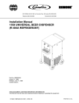
FIGURE 1. AURORAR10,000 COOLING UNIT
1
300381000
Table 1. Design Data
COOLING UNIT MODEL NUMBERS:
60 HZ Unit:
Standard Cooling Unit with Internal Condenser Coil and Fan Assembly
Cooling Unit Requiring Connection to Remote Condenser Coil and Fan
Assembly
50 HZ Unit:
Standard Cooling Unit with Internal Condenser Coil and Fan Assembly
416593
416594
496593
COOLING UNIT DATA
Overall Dimensions:
Height
Width
Depth
28-inches
36-1/2 inches
24-1/2 inches
NOTE: Overall dimensions if Cooling Unit is placed on optional Cooling Unit Stand (P/N 309309069).
Height (approximate)
75-5/16 inches
Width
37-1/2 inches
Depth
25-3/8 inches
Weights:
Models 416593 and 496593:
Shipping
Dry Weight
378 pounds
358 pounds
Model 416594:
Shipping
Dry Weight
Ice Bank Weight
Capacities:
Water Bath (no ice bank)
Compressor Horsepower
381 pounds
361 pounds
40 to 45 pounds
18 gallons
2 HP
Refrigeration System:
Refrigerant Type and Charge
See Cooling Unit Nameplate
Ambient Operating Temp.
50°F to 100°F
Electrical Requirements:
60 HZ Cooling Unit:
Operating voltage
Current Draw
See Cooling Unit
Nameplate
50HZ Cooling Unit:
Operating Voltage
Current Draw
300381000
See Cooling
Unit
Nameplate
2
Table 1. Design Data (cont’d)
REMOTE CONDENSER COIL AND FAN ASS’Y DATA (P/N 309602000)
Overall Dimensions:
Height
Width
Depth
Weight:
Shipping
27 inches
22-inches
38-inches
85 pounds
Ambient Operating Temp.
Electrical Requirements:
Operating Voltage
-22°F to 158°F
208/230VAC, Single Phase,
60Hz
2.5 Amps
Current Draw
SYSTEM THEORY OF OPERATION
(see Figure 2)
A CO2 cylinder delivers carbon dioxide gas (CO2) to primary CO2 regulator assembly which delivers regulated
CO2 gas to adjustable secondary CO2 regulators. Secondary CO2 regulators deliver regulated CO2 gas to both
carbonated water tanks inside Cooling Unit and also to soft drink tanks. Plain water is pumped into carbonated
water tanks by water pumps and is carbonated by regulated CO2 gas pressure also entering tanks. Carbonated
water leaves carbonated water tanks and passes through the Hydro BoostR(carbonated water pre-cooler)
which pre-cools carbonated water on its way to carbonated water circulating pump. Pre-cooled carbonated
water enters carbonated water circulating system through inlet side of carbonated water circulating pump.
Carbonated water passes from outlet side of carbonated water circulating pump, through cooling coils inside
water tank, and out through insulated line to turnaround inside dispensing station. Carbonated water returns to
Cooling Unit by passing through insulated line, through cooling coils, and on to carbonated water circulating
pump inlet which makes up the carbonated water circulating system. As carbonated water is being dispensed
from dispensing station, carbonated water circulating system is continuously being replenished from both
carbonated water tanks. Regulated CO2 gas pressure, exerted upon soft drink tanks contents, forces syrup
from tanks, through Cooling Unit cooling coils, and on to dispensing station through insulated lines.
Standard Cooling Unit.
The standard Cooling Unit refrigeration system is cooled by a condenser coil and fan assembly located inside
Cooling Unit.
Cooling Unit Requiring Connection to Remote Condenser Coil and Fan Assembly.
The Cooling Unit refrigeration system is cooled by a Remote Condenser Coil and Fan Assembly
(P/N 309602000) that is authorized by IMI Cornelius Inc. Use of any other Remote Condenser Coil and Fan
Assembly must be authorized by IMI Cornelius Inc. Use of an unauthorized Remote Condenser Coil and Fan
Assembly will automatically void the Cooling Unit factory warranty.
3
300381000
300381000
4
WATER PRESSURE
REGULATOR
CO2 CYLINDER
PRIMARY CO2
REGULATOR
GAS CHECK
VALVE(2)
CARBONATORS CO2
REGULATORS
SUGAR SYRUP
CO2 REGULATOR
LINE LEGEND
CO2
PLAIN WATER
CARB WATER
SYRUP
PLAIN WATER
SOURCE
SHUTOFF
VALVE
CO2 GAS CHECK VALVE
DOUBLE
LIQUID
CHECK
VALVE(2)
CARBONATED
WATER
CIRCULATING
PUMP
TEE FITTING
FIGURE 2. FLOW DIAGRAM (TYPICAL INSTALLATION)
SOFT DRINK TANKS
CO2 GAS CHECK
VALVE(5)
CO2 MANIFOLD
DIET SYRUP
CO2 REGULATOR
PLAIN WATER
SHUTOFF VALVE
WATER FILTER
ASS’Y
SYRUP
LINES
CARBONATED
WATER TANK(2)
CARBONATOR
WATER PUMP(2)
HYDDRO
BOOSTR
PLAIN WTR
CARB WTR
CARB WTR
SINGLE
LIQUID
CHECK
VALVE(2)
CARBONATED
WATER
SHUTOFF
VALVE(2)
EXTERNAL
CARBONATOR
CHECK
VALVE
HYDRO BOOSTR
BYPASS VALVE
INSTALLATION
This section covers unpacking and inspection, selecting location, installing Cooling Unit, preparing for operation,
and operation.
UNPACKING AND INSPECTION
NOTE: The Cooling Unit was thoroughly inspected before leaving the factory and the carrier has
accepted and signed for it. Any damage or irregularities should be noted at time of delivery (or not later
than 15 days from date of delivery) and immediately reported to the delivering carrier. Request a written
inspection report from Claims Inspector to substantiate any necessary claim. File claim with the
delivering carrier, not with IMI Cornelius Inc.
1. After Cooling Unit has been unpacked, remove shipping tape and other packing material.
2. Unpack LOOSE-SHIPPED PARTS. Make sure all items are present and in good condition.
Table 2. Loose-Shipped Parts
Item
No.
Part No.
Name
Qty.
1
110085000
Tubing Clamp
2
2
111353000
Tubing Clamp
7
3
311962000
Label, Line Identification
1
NOTE: The following Remote Condenser Coil and Fan Assembly and Refrigeration Lines Kits are recommended for use with the Cooling
Units.
4
309602000
Remote Condenser Coil and Fan Ass’y
1
5
300598025
Refrigeration Line Kit, 25-ft. long, 90°
1
300598050
Refrigeration Line Kit, 50-ft. long, 90° Straight
1
IDENTIFICATION OF LOOSE-SHIPPED PARTS
1. TUBING CLAMPS (item 1) used to secure insulated python lines to Cooling Unit carbonated water outlet
lines.
2. TUBING CLAMPS (item 2) used to secure insulated python lines to Cooling Unit syrup and plain water
lines.
3. REFRIGERATION LINE KITS (item 5) is used to connect the REMOTE CONDENSER COIL AND FAN
ASS’Y (item 4) to the Cooling Unit.
SELECTING LOCATION
COOLING UNIT
Select location for Cooling Unit installation that will (1) Allow the shortest possible insulated python route from
the Cooling Unit to the Dispensing Station location; (2) Allow the shortest possible refrigeration lines (not to
exceed 50-ft in length) route from Remote Condenser Coil and Fan Assembly to the Cooling Unit; (3) REFER
TO THE COOLING UNIT NAMEPLATE FOR THE REQUIRED POWER CIRCUIT OPERATING VOLTAGE, HZ,
AND THE MINIMUM CIRCUIT AMPACITY OF THE COOLING UNIT. The power circuit for the Cooling Unit
must be wired through a 40-amp minimum rated disconnect switch (not provided) and the power circuit must be
5
300381000
fused as indicated on the Unit nameplate. The power circuit may also be wired through an equivalent HACR
type circuit breaker rather then the disconnect switch. THE POWER CIRCUIT MUST BE MADE UP OF
COPPER CONDUCTORS AND ALL WIRING MUST CONFORM TO NATIONAL AND LOCAL ELECTRICAL
CODES; (4) Close to a plain water source supply line with proper requirements; (5) Allow sufficient space
around Cooling Unit (see Figure 4) for proper air circulation (18-inches on sides and back, front side open to
room, and top open to ceiling); (6) Be close to permanent floor drain to route Cooling Unit water tank drain and
overflow hoses to the floor drain.
REMOTE CONDENSER COIL AND FAN ASS’Y (IF APPLICABLE)
1. An extreme warm climate installation may require extra caution in Remote Rooftop Condenser Coil and
Fan Assembly location. Avoid hot sunny locations and seek shaded area if possible. The use of structure
to shade unit from direct sun exposure and/or a platform extending unit an additional 18-inches above
rooftop is highly recommended and will improve performance. Ample space must be provided on all sides
and above unit for proper air circulation through unit and also access for service and maintenance. DO
NOT BLOCK AIR CIRCULATION THROUGH UNIT.
2. Remote Condenser Coil and Fan Assembly must be installed in level position and must be anchored to
rooftop with adequate fastening devices.
INSTALLING REMOTE CONDENSER COIL AND FAN ASS’Y (IF
APPLICABLE)
see Figure 6
1. Remote Condenser Coil and Fan Assembly must be installed meeting requirements of SELECTING
LOCATION. Remote Condenser Coil and Fan Assembly must be installed in level position and must be
anchored to with adequate fastening devices.
2. Route REFRIGERATION LINES (item 5) from Remote Condenser Coil and Fan Assembly down to Cooling
Unit location.
3. Connect ends of refrigeration lines to Remote Condenser Coil and Fan Assembly refrigeration connectors.
INSTALLING COOLING UNIT
NOTE: Cooling Unit outlet lines, plain water, CO2, and syrup inlet lines, Remote Condenser Coil and
Fan Assembly refrigeration lines and power circuit cable (if applicable), and Cooling Unit power circuit
cable each must be long enough when connected to Cooling Unit to allow pulling unit out
approximately 36-inches from operating position for service and maintenance. When Cooling Unit is in
operating position, excess power circuit cable, Remote Condenser Coil and Fan Assembly refrigeration
lines and power circuit cable (if applicable) and plain water source and CO2 inlet lines may be coiled up
behind unit.
NOTE: An external carbonator may be connected to Cooling Unit as shown in Figure 2 for larger supply
of carbonated water.
PLACING COOLING UNIT IN LOCATION
NOTE: An optional Cooling Unit Stand (P/N 309309069) is available to elevate Cooling Unit up off floor.
1. Place Cooling Unit in position approximately 36-inches out from operating position to allow access all
around unit.
2. Remove two screws securing Cooling Unit top cover, then remove cover.
300381000
6
CONNECTING REMOTE CONDENSER COIL AND FAN ASS’Y (IF APPLICABLE)
REFRIGERATION LINES TO COOLING UNIT
(see Figure 6 )
Connect refrigeration lines, from Remote Condenser Coil and Fan Assembly, to refrigeration connectors on
back of Cooling Unit.
CONNECTING ELECTRICAL POWER CIRCUIT TO COOLING UNIT
(see Figures 5 or 6 and 15)
IMPORTANT: Before applicable single-phase 60HZ or 50HZ electrical power circuit is connected to the
Cooling Unit, service power voltage entering the building must be identified. Service power voltage
entering the building will either be 208 or 230VAC and may be posted on the main service box. If not,
the installer must contact the local electrical power company for information. If these two voltage
identification attempts should fail, a voltage reading must be performed. If service power voltage is
below 218VAC, the red electrical wire connected to the 240VAC terminal on LINE (primary) side of the
240/24VAC power transformer inside the Cooling Unit switches electrical control box (see Figure 3 and
15) must be disconnected from the 240VAC terminal and be connected to the 208VAC terminal. If
voltage is above 218VAC, power transformer red electrical wire will remain connected to the 240VAC
terminal. If installer is not sure of the service power voltage entering the building, leave the red
electrical wire connected to the 240VAC terminal on the power transformer. If service power voltage is
below 218VAC, proceed as follows:
1. Remove four screws securing switches electrical control box (see Figure 5 or 6) to Cooling Unit cabinet.
2. Pull switches electrical control box out for access to the 240/24VAC power transformer.
3. Remove red electrical wire from the 240VAC terminal on LINE (primary) side of power transformer and
connect it to the 208 VAC terminal.
4. Install Cooling Unit switches electrical control box and secure with four screws.
C
208V
240V
RESET BUTTON
FIGURE 3. 240/24VAC POWER TRANSFORMER
WARNING: Make sure 40-amp minimum-rated disconnect switch or HACR circuit breaker (if
applicable) is in ‘‘OFF’’position.
1. Remove cover from electrical box on back of Cooling Unit.
7
300381000
WARNING: The Cooling Unit must be electrically grounded to avoid possible fatal electrical
shock or serious injury to the operator. A green ground wire is provided inside electrical
box to connect power circuit ground wire which electrically grounds the Cooling Unit.
2. 60HZ Cooling Unit
Connect 208/230VAC Single Phase 60Hz electrical power circuit with a 40-amp minimum rated disconnect
switch (not provided) fused at 40-amps (maximum) or circuit connected through an equivalent HACR circuit
breaker to electrical wires inside electrical handy box on back of cooling unit. DO NOT CONNECT
ELECTRICAL POWER TO COOLING UNIT AT THIS TIME.
COOLING UNIT MUST BE PROPERLY GROUNDED, POWER CIRCUIT MUST BE MADE UP OF
COPPER CONDUCTORS, AND ALL WIRING MUST CONFORM TO NATIONAL AND LOCAL
ELECTRICAL CODES.
50HZ Cooling Unit
Connect 208/230VAC Single Phase 50Hz electrical power circuit with a 40-amp minimum rated disconnect
switch (not provided) fused at 40-amps (maximum) or circuit connected through an equivalent HACR circuit
breaker to electrical wires inside electrical handy box on back of cooling unit. DO NOT CONNECT
ELECTRICAL POWER TO COOLING UNIT AT THIS TIME.
COOLING UNIT MUST BE PROPERLY GROUNDED, POWER CIRCUIT MUST BE MADE UP OF COPPER
CONDUCTORS, AND WIRING MUST CONFORM TO APPLICABLE ELECTRICAL CODES.
CONNECTING ELECTRICAL POWER CIRCUIT TO REMOTE CONDENSER COIL AND FAN ASS’Y (IF
APPLICABLE) see Figures 6 and 15)
CAUTION: The Cooling Unit refrigeration system is cooled by a Remote Condenser Coil
and Fan Assembly (P/N 309602000) that is authorized by IMI Cornelius Inc. Use of an
unauthorized Remote Condenser Coil and Fan Assembly will automatically void the
Cooling Unit factory warranty.
Remote Condenser Coil and Fan Assembly (P/N 309602000)
NOTE: Electrical power circuit may be connected to the Remote Condenser Coil and Fan Assembly
(P/N 309602000) in two ways. The preferred way is to draw electrical power from the Cooling Unit
contactor which allows the Remote Condenser Coil and Fan assembly to operate only when the
Cooling Unit refrigeration system is operating. The optional way is to connect a separate electrical
power circuit (independent of the cooling unit) through an appropriately rated and fused disconnect
switch or an equivalent HACR circuit breaker which allows the Remote Condenser Coil and Fan
Assembly to operate at all times (independent of Cooling Unit operation).
Connect and route electrical power circuit cable from Remote Condenser Coil and Fan Assembly through fuse
box (not provided), fused at 15-amps (maximum) down to Cooling Unit location. REMOTE CONDENSER COIL
AND FAN ASSEMBLY MUST BE PROPERLY GROUNDED, POWER CIRCUIT MUST BE MADE UP OF
COPPER CONDUCTORS, AND ALL WIRING MUST CONFORM TO NATIONAL AND LOCAL ELECTRICAL
CODES.
A.
Remove four screws securing electrical control box to Cooling Unit back panel, (see Figure 6) then
pull control box out for access to contactor inside box.
B.
Route Remote Condenser Coil and Fan Assembly power cable electrical wires through electrical
handy box on back of Cooling Unit to inside of electrical control box.
C.
Connect Remote Condenser Coil and Fan Assembly power cable electrical wires to T1 and T2
terminals on contactor inside Cooling Unit electrical control box.
300381000
8
D.
Reinstall Cooling Unit electrical control box and secure with four screws.
E.
Install cover on electrical handy box on back of Cooling Unit.
CONNECTING PLAIN WATER INLET SUPPLY LINE TO COOLING UNIT
(see Figure 2)
NOTE: IMI Cornelius Inc. recommends that a water shutoff valve be installed in plain water inlet supply
line connected to Cooling Unit and that water supply be filtered. WATER PIPE CONNECTIONS AND
FIXTURES DIRECTLY CONNECTED TO A POTABLE WATER SUPPLY SHALL BE SIZED, INSTALLED
AND MAINTAINED ACCORDING TO FEDERAL, STATE, AND LOCAL LAWS.
CAUTION: Plain water inlet supply line to Cooling Unit must be 1/2-inch I.D. minimum.
Check water flow rate of water inlet supply line. MINIMUM FLOW RATE MUST BE AT LEAST
250-GALLONS PER HOUR. If flow rate is less than 250-gallons per hour, ‘‘starving’’of
carbonator water pump will occur. Starving will allow water pump to overheat causing safety
thermostat on pump outlet to disrupt electrical power to and stop water pump motor. Carbonated
water circulating pump overheating could occur if water inlet supply line flow rate drops below
250-gallons per hour. INCOMING PLAIN WATER INLET SUPPLY LINE WATER PRESSURE MUST
REMAIN A MINIMUM OF 10-PSI BELOW THE CARBONATOR CO2 OPERATING PRESSURE
(Example: operating CO2 pressure is 90-psi and maximum water pressure can be no more than
80-psi, etc.)
1. Before connecting plain water inlet supply line to Cooling Unit, open water line shutoff valve for a period of
time to flush out any metal shavings and other contaminates that may have resulted from plumbing
connections.
2. Connect flexible plain water inlet supply line (1/2-inch I.D. min.), meeting water inlet supply line
requirements of preceding CAUTION note, to Cooling Unit 3/8-in. flare (5/8-18) bulkhead fitting on back of
unit labeled ‘‘WATER INLET’’. DO NOT OPEN WATER INLET SUPPLY LINE SHUTOFF VALVE AT THIS
TIME.
CONNECTING CO2 INLET SUPPLY LINE TO COOLING UNIT
(see Figure 2)
WARNING: CO2 displaces oxygen. Strict attention must be observed in the prevention of
CO2 (carbon dioxide) gas leaks in the entire CO2 and soft drink system. If a CO2 gas leak is
suspected, particularly in a small area, immediately ventilate the contaminated area before
attempting to repair the leak. Personnel exposed to high concentration of CO2 gas will experience
tremors which are followed rapidly by loss of consciousness and suffocation.
Connect flexible CO2 inlet supply line to Cooling Unit 1/4-in. flare (7/16-20) bulkhead fitting of back of unit
labeled ‘‘CO2 INLET’’. DO NOT TURN ON CO2 SUPPLY TO COOLING UNIT AT THIS TIME.
CONNECTING SYRUP SOURCE LINES TO COOLING UNIT SYRUP INLET LINES
(see Figure 2 )
Connect syrup source lines, from No. 1 through No. 6 soft drink tanks location, to Cooling Unit syrup inlet lines
labeled No. 1 through No. 6. DO NOT CONNECT SOFT DRINK TANKS INTO SYRUP SYSTEMS AT THIS
TIME.
9
300381000
CONNECTING COOLING UNIT SYRUP OUTLET LINES TO INSULATED PYTHON SYRUP
LINES
(see Figure 2)
Connect Cooling Unit syrup outlet lines labeled No. 1 through No. 6, with barbed fittings on their ends, to
insulated python lines labeled No. 1 through No. 6. Secure connections with TUBING CLAMPS (item 2).
CONNECTING COOLING UNIT PLAIN WATER OUTLET LINE TO INSULATED PYTHON
PLAIN WATER LINE
(see Figure 2)
NOTE: Shutoff valve in plain water line inside Cooling Unit must remain closed if plain water is not
desired at dispensing valve.
Connect Cooling Unit plain water outlet line, with barbed fitting on its end, to insulated python plain water line.
Secure connection with TUBING CLAMP (item 2).
CONNECTING COOLING UNIT CARBONATED WATER OUTLET LINES TO INSULATED
PYTHON CARBONATED WATER LINES
(see Figure 2)
Connect Cooling Unit carbonated water outlet lines, with barbed connectors on their ends, to insulated python
carbonated water lines. secure Connections with TUBING CLAMPS (item 1).
PLACING COOLING UNIT IN OPERATING POSITION
1. Very carefully, move Cooling Unit back into operating position leaving space around unit (see Figure 4) as
specified in SELECTING LOCATION. MAKE SURE THERE ARE NO KINKS IN SYRUP INLET LINES,
INSULATED PYTHON INTERNAL LINES, CO2 AND PLAIN WATER INLET LINES, AND REMOTE
CONDENSER AND FAN ASSEMBLY REFRIGERATION LINES (IF APPLICABLE).
NOTE: To comply with National Sanitation Foundation (NSF) requirements, Cooling Unit not installed
on optional Cooling Unit Stand (P/N 309309069) must have its base sealed to floor with Dow-Corning
RTV 731 or equivalent.
1. Tilt Cooling Unit up to expose bottom of unit base.
2. Liberally apply silastic sealant such as Dow Corning (RTV 731) or equivalent on unit base bottom edges.
NOTE: Do not move Cooling Unit after positioning or seal from unit base to floor will be broken.
18-- IN.
18-- IN.
COOLING UNIT
18-- IN.
AIR FLOW
(OPEN TO ROOM)
FIGURE 4. COOLING UNIT SPACE REQUIRED
300381000
10
3. Lower Cooling Unit into operating position to complete seal from unit base to floor. Apply additional sealant
around bottom of base. Seal must have a minimum radius of 1/2-inch to prevent cracks and crevices and
to ensure a complete seal.
4. Route Cooling Unit water tank overflow hose to permanent floor drain.
5. Seal area around overflow hose where they exit from unit using permagum sealant or equivalent.
PREPARING COOLING UNIT FOR OPERATION
1. Make sure plug in end of Cooling Unit water tank drain hose is secure.
2. Open shutoff valve in plain water inlet supply line. Due to slow water fill rate of water level float control,
water tank may be hand filled until water runs out of water tank overflow hose. CLEAN
LOW-MINERAL-CONTENT WATER MUST BE USED WHERE A LOCAL WATER PROBLEM EXIST.
3. Adjust primary CO2 regulator (see Figure 2) on CO2 cylinder to a minimum nominal setting of 120-psi or
24-psi higher than highest setting required by the secondary CO2 regulators. Loosen CO2 regulator
adjusting screw locknut. Turn adjusting screw to the right (clockwise) until regulator gage registers nominal
120-psi, then tighten adjusting screw locknut.
4. Adjust carbonators secondary CO2 regulator (see Figure 2) to a nominal 90-psi. Loosen CO2 regulator
adjusting screw locknut. Turn adjusting screw to the right (clockwise) until regulator gage registers nominal
90-psi, then tighten adjusting screw lock nut. CO2 PRESSURE TO CARBONATORS MUST NOT EXCEED
120-PSIG.
CAUTION: Before starting refrigeration system, Hydro Boostâ coil must be completely
flooded with carbonated water to prevent coil freeze-up. Proceed as follows to fill
carbonated water system.
5. Make sure both carbonated water shutoff valves inside Cooling Unit (see Figure 2) are in ‘‘OPEN’’(handles
in line with tubing) positions.
6. Make sure Hydro Boostâ bypass valve inside Cooling Unit (see Figure 2) is in ‘‘CLOSED’’(handle not in
line with tubing) position.
7. Make sure Cooling Unit REFRIGERATION POWER, CARBONATOR MOTORS, and CIRCULATING
MOTOR Power switches are in ‘‘OFF’’(down) positions.
8. Connect electrical power to Cooling Unit at disconnect switch.
9. Place CARBONATOR MOTORS power switch in ‘‘ON’’(up) position to start carbonators.
10. Dispense from dispensing station until carbonated water appears at valve indicating Hydro Boostâ and
carbonated water system have been completely filled with carbonated water.
OPERATION
WARNING: Disconnect electrical power to Cooling Unit and Remote Condenser Coil and
Fan Assembly (if applicable) to prevent personal injury before attempting any Cooling Unit
or Remote Condenser Coil and Fan Assembly internal maintenance. Only qualified
personnel should service internal components or electrical wiring.
11
300381000
STARTING COOLING UNIT REFRIGERATION SYSTEM
NOTE: As ice bank forms in water tank, water expansion will take place and excess water will escape
through water tank overflow hose to permanent floor drain.
Cooling Unit Connected To Remote Condenser Coil and Fan Assembly. (P/N 309602000).
Place Cooling Unit REFRIGERATION POWER switch in ‘‘ON’’(up) position. Refrigeration compressor,
compressor cooling fan, agitator motor, and Remote Condenser Coil and Fan Assembly will start. Cooling Unit
will begin forming an ice bank and refrigerated Hydro Boostâ coil will also be chilling water. When full ice bank
has been formed, Remote Condenser oil and Fan Assembly, Cooling Unit compressor, and compressor cooling
fan will stop but agitator motor will continue to operate circulating ice water bath in water tank.
Standard Cooling Unit Utilizing Condenser Coil and Fan Assembly.
Place Cooling Unit REFRIGERATION POWER switch in ‘‘ON’’(up) position. Refrigeration compressor,
condenser fan motor, and agitator motor will start and begin forming an ice bank. When full ice bank has been
formed, compressor and condenser fan motor will stop but, agitator motor will continue to operate circulating ice
water bath in water tank.
STARTING CARBONATED WATER CIRCULATING PUMP
1. Place CIRCULATING MOTOR power switch in ‘‘ON’’(up) position. Circulating pump will start and begin
circulating carbonated water in system.
2. Dispense carbonated water from dispensing valve to make sure all air has been purged from system.
3. If Cooling Unit plain water outlet line is connected to dispensing system, open plain water shutoff valve
inside unit. Dispense from valve until all air is purged from plain water system.
ACTIVATING SYRUP SYSTEMS
1. Adjust soft drink tanks secondary CO2 regulators (see Figure 2) as follows:
Sugar Syrup Soft Drink Tanks CO2 Regulator.
Adjust sugar syrup soft drink tanks secondary CO2 regulator at 40-psig for syrup lines up to 10-feet in
length plus one pound for each additional length of 10-feet, plus one pound for each 2-feet of vertical lift.
For example: if syrup line total length is 30-feet and total vertical lift is 6-feet, then 40-psig + 2-psig
(1-pound for every 10-feet of length over 10-feet which is 20-feet) + 3-psig (1-pound for every 2-feet of
vertical lift which is 6-feet); total equals 40 + 2 + 3 = 45-psig CO2 regulator setting.
Low-Calorie (diet) Syrup Soft Drink Tank CO2 Regulator.
Adjust low-calorie (diet) soft drink tank secondary CO2 regulator for low-calorie drink at 10-psig for syrup
lines up to 30-feet in length. Syrup lines longer than 30-feet in length may require a slightly higher CO2
regulator setting to 12-psig maximum. Excessive CO2 pressure may cause low-calorie syrup carbonation
resulting in foam.
IMPORTANT: Syrup systems must be sanitized as instructed before syrup is connected into syrup
systems.
2. Connect soft drink tanks into syrup systems.
3. Dispense from all dispensing stations dispensing valves until product is dispensed.
300381000
12
LEAK CHECK AND INSULATING COOLING UNIT OUTLET LINES
1. Check all CO2, plain and carbonated water, and syrup connections for leaks and repair if evident.
2. Make sure Cooling Unit outlet lines connections to insulated python lines are well insulated.
3. Install Cooling Unit top cover and secure with two screws.
DISPENSING STATION ADJUSTMENTS
ADJUSTING WATER FLOW RATE
Refer to Installation Instructions provided with dispensing station for dispensing valve water flow rate adjustment
instructions.
ADJUSTING WATER-TO-SYRUP ‘‘RATIO’’OF DISPENSED PRODUCT
Adjust dispensing station dispensing valves for Water- to-Syrup ‘‘Ratio’’of dispensed product as instructed in
dispensing station Installation Instructions.
INSTALLING LINE IDENTIFICATION LABEL
Install LABEL, LINE IDENTIFICATION (item 3) on Cooling Unit and record syrup flavors in proper spaces.
13
300381000
THIS PAGE LEFT BLANK INTENTIONALLY
300381000
14
OPERATORS INSTRUCTIONS
This section covers operating controls, daily pre-operation check, adjustments, replenishing CO2 and syrup
supplies, cleaning and sanitizing, Cooling Unit maintenance, Remote Condenser Coil and Fan Assembly (if
applicable) maintenance, lubrication, and servicing CO2 gas check valves.
WARNING: Disconnect electrical power to Cooling Unit to prevent personal injury before
attempting any Cooling Unit or Rooftop Condenser Coil and Fan Assembly (if applicable)
internal maintenance. Only qualified personnel should service internal components or
electrical wiring.
OPERATING CONTROLS
COOLING UNIT REFRIGERATION POWER SWITCH
(see Figure 5 or 6)
REFRIGERATION POWER switch, located on front of Cooling Unit, placed in ‘‘OFF’’position will interrupt
electrical power to refrigeration compressor, agitator motor, condenser fan motor (if applicable), and carbonated
water circulating pump. Switch must be in ‘‘ON’’(up) position for operation. REFRIGERATION POWER
SWITCH DOES NOT DISRUPT ELECTRICAL POWER TO CARBONATORS PUMPS MOTORS.
COOLING UNIT CARBONATOR MOTOR SWITCH
(see Figure 5 or 6)
CARBONATOR MOTORS power switch, located on front of Cooling Unit, placed in ‘‘OFF’’(down) position will
interrupt electrical power to both carbonators pumps motors. Switch must be placed in ‘‘ON’’(up) position before
carbonators will operate.
COOLING UNIT CIRCULATING MOTOR SWITCH
(see Figure 5 or 6)
CIRCULATING MOTOR power switch, located on front of Cooling Unit, placed in ‘‘OFF’’(down) position will
interrupt electrical power to carbonated water circulating pump. Switch must be placed in ‘‘ON’’(up) position
before circulating pump will operate.
REFRIGERATION SYSTEM TEMPERATURE SENSING DEVICE AND HIGH-PRESSURE
CUTOUT SWITCH
Cooling Unit with Internal Condenser Coil and Fan Assembly.
(see Figure 5)
The Cooling Unit is equipped with a refrigeration system temperature sensor which will automatically initiate
shutdown if the temperature of the liquid return line from the condenser exceeds 155°F. Temperature rise may
be caused by a clogged condenser coil air intake filter, or refrigeration components problem. After cool down,
the refrigeration system will restart as required.
CAUTION: If the refrigeration system continues to ‘‘short cycle’’following restart,
immediate attention is required to avoid compressor failure.
15
300381000
Cooling Unit Connected to Remote Condenser Coil and Fan Assembly.
(see Figure 6)
This Cooling Unit is equipped with a refrigeration system temperature sensing device and a high-pressure
sensing cutout switch that will shut refrigeration system down should the system overheat due to a clogged
condenser coil in the Remote Condenser Coil and Fan Assembly. If refrigeration system does not automatically
restart itself after system has cooled down, high-pressure sensing cutout switch reset button (see Figure 6) will
have to be pressed to reset switch. MAKE SURE REFRIGERATION SYSTEM PROBLEM IS CORRECTED.
OPERATING REFRIGERATION SYSTEM IN THIS MANNER FOR PROLONGED PERIOD OF TIME COULD
RESULT IN COMPRESSOR FAILURE.
DAILY PRE-OPERATION CHECK
1. Make sure CO2 cylinder regulator assembly 1800-psi gage indicator is not in shaded (‘‘change CO2
cylinder’’) portion of dial. If so, CO2 cylinder is almost empty and must be replaced.
2. Sufficient syrup supply in all soft drink tanks. If not, replenish syrup supply as instructed.
ADJUSTMENTS
ADJUSTING CO2 REGULATORS
CO2 regulators should be periodically checked for proper pressure settings and if necessary, adjusted as
instructed.
ADJUSTING DISPENSING VALVES WATER FLOW RATE
If adjustment of dispensing valves water flow rate should be necessary, adjust as instructed in dispensing
station Installation Instructions.
ADJUSTING WATER-TO-SYRUP ‘‘RATIO’’OF DISPENSED PRODUCT
Water-To-Syrup ‘‘Ratio’’of dispensed product should be checked and if necessary, adjusted as instructed in
dispensing station Installation Instructions.
ADJUSTING SIZE OF DRINK DISPENSED
Adjust drink size of dispensed product as instructed in dispensing station Installation Instructions.
ADJUSTING CARBONATOR TANK LIQUID LEVEL
The carbonator tank liquid level (40 to 60-ounces) pump cut-in and cut-out were adjusted at the factory and
should require no further adjustment. If incorrect adjustment is suspected, adjust as instructed.
REPLENISHING CO2 SUPPLY
WARNING: CO2 displaces oxygen. Strict attention must be observed in the prevention of
CO2 (carbon dioxide) gas leaks in the entire CO2 and soft drink system. If a CO2 gas leak is
suspected, particularly in a small area, immediately ventilate the contaminated area before
attempting to repair the leak. Personnel exposed to high concentration of CO2 gas will experience
tremors which are followed rapidly by loss of consciousness and suffocation.
300381000
16
NOTE: When indicator on CO2 cylinder regulator assembly 1800-psi gage is in shaded (‘‘change CO2
cylinder’’) portion of the dial, CO2 cylinder is almost empty and should be changed. CO2 supply should
be checked daily and if necessary, replenished as instructed.
REPLENISHING SYRUP SUPPLY
Syrup supply should be checked daily and if necessary, replenished as instructed.
CLEANING AND SANITIZING
DAILY CLEANING
Perform daily cleaning of dispensing station as instructed in dispensing station Installation Instructions. Outside
of Cooling Unit must be cleaned periodically.
SANITIZING SYRUP SYSTEMS
Syrup systems should be sanitized every 90 days as instructed following Sanitizer Manufacturer’s
recommendations.
COOLING UNIT MAINTENANCE
COOLING UNIT EQUIPPED WITH CONDENSER COIL AND AIR INTAKE FILTER
CAUTION: Cooling Unit equipped with condenser coil is equipped with an air filter that
must be cleaned every 30 days as instructed. Circulating air, required to cool the coil, is
drawn in through air filter on back, and is exhausted out through coil on front of Unit.
Failure to clean and allowing air filter to become clogged, will cause refrigeration system to
overheat which will automatically shut refrigeration system down. After refrigeration system has
cooled down, system will automatically restart and operate until overheated and shut down again.
OPERATING COOLING UNIT IN THIS MANNER FOR PROLONGED PERIOD OF TIME COULD
RESULT IN COMPRESSOR FAILURE.
Area around Cooling Unit must be kept free of obstructions at all times for proper air circulation through the Unit.
Air filter must be cleaned every 30 days as instructed.
COOLING UNIT CARBONATOR MAINTENANCE
Lubrication
Carbonator water pump motor bearings must be oiled periodically as instructed.
Water Pump Yearly Maintenance (or After Water System Disruptions).
Carbonator water pump water strainer screen and liquid double check valve must be inspected and cleaned at
least once a year under normal circumstances and after any water system disruption (plumbing work,
earthquake, etc.). Inspect and clean water strainer screen and liquid double check valve as instructed.
17
300381000
COOLING UNIT CARBONATED WATER CIRCULATING PUMP MOTOR LUBRICATION
Carbonated water circulating pump motor bearings must be oiled periodically as instructed.
REMOTE CONDENSER COIL AND FAN ASS’Y (IF APPLICABLE)
MAINTENANCE
(see Figure 6)
CAUTION: Remote Condenser Coil and Fan Assembly connected to this Cooling Unit is
equipped with a condenser coil that must be cleaned every 30-days. Allowing condenser
coil to become clogged will cause refrigeration system to overheat which will automatically
shut refrigeration system down. After condenser coil has been cleaned, high-pressure cutout
switch reset button on top of switches electrical control box under Cooling Unit top cover will
have to be pressed to restart refrigeration system. OPERATING COOLING UNIT IN THIS MANNER
FOR PROLONGED PERIOD OF TIME COULD RESULT IN COMPRESSOR FAILURE.
Area on top of and around Remote Condenser Coil and Fan Assembly must be kept free of obstructions at all
times. Condenser coil must be cleaned as instructed to maintain proper cooling of coil.
CLEANING CO2 GAS CHECK VALVES
(see Figure 2 )
The CO2 gas check valves must be inspected and serviced at least once a year under normal conditions and
after any CO2 system servicing or disruption as instructed.
300381000
18
SERVICE AND MAINTENANCE
This section describes Service and Maintenance procedures to be performed on the Cooling Unit and the
Remote Condenser Coil and Fan Assembly.
WARNING: Disconnect electrical power to Cooling Unit to prevent personal injury before
attempting any Cooling Unit or Remote Rooftop Condenser Coil and Fan Assembly (if
applicable) internal maintenance. Only qualified personnel should service internal
components or electrical wiring.
PREPARING COOLING UNIT FOR SHIPPING, STORING, OR RELOCATING
CAUTION: Before shipping, storing, or relocating Cooling Unit, syrup systems must be
sanitized and all sanitizing solution must be purged from syrup systems. All water must be
purged from plain and carbonated water systems and ice bank must be melted and all
water drained from water tank. A freezing ambient environment will cause residual water remaining
inside unit to freeze resulting in damage to internal components.
PERIODIC INSPECTION
Cooling Unit Equipped With Condenser Coil and Air Intake Filter.( see Figure 5 )
CAUTION: Cooling Unit equipped with condenser coil is equipped with an air filter that
must be cleaned every 30 days as instructed. Circulating air, required to cool the coil, is
drawn in through air filter on back, and is exhausted out through coil on front of Unit.
Failure to clean and allowing the air filter to become clogged, will cause refrigeration system to
overheat which will automatically shut refrigeration system down. After refrigeration system has
cooled down, system will automatically restart and operate until overheated and shut down again.
OPERATING COOLING UNIT IN THIS MANNER FOR PROLONGED PERIOD OF TIME COULD
RESULT IN COMPRESSOR FAILURE.
Clean air filter every 30 days as instructed. Area around Cooling Unit must be kept free of obstructions at all
times for proper air circulation through the unit.
Cooling Unit Utilizing a Remote Condenser Coil and Fan Assembly.
CAUTION: Remote Condenser Coil and Fan assembly connected to this Cooling Unit is
equipped with a condenser coil that must be cleaned every 30-days. Allowing condenser
coil to become clogged will cause refrigeration system to overheat which will automatically
shut refrigeration system down. After condenser coil has been cleaned, high-pressure cutout
switch reset button on top of switches electrical control box under Cooling Unit top cover will
have to be pressed to restart refrigeration system. OPERATING COOLING UNIT IN THIS MANNER
FOR PROLONGED PERIOD OF TIME COULD RESULT IN COMPRESSOR FAILURE.
Clean Remote Condenser Coil and Fan Assembly condenser coil every 30 days, as instructed. Make sure area
on top and around unit are kept free of obstructions at all times. Air must be allowed to enter and leave unit to
remove heat from condenser coil. Restricting air through condenser coil will cause Cooling Unit refrigeration
system to overheat.
3. Check entire system for leaks or damaged components. Repair as necessary.
19
300381000
COOLING UNIT MAINTENANCE
PERIODIC CLEANING
Periodically wash all external surfaces of Cooling Unit, rinse with clean water, then wipe dry with a clean soft
cloth. DO NOT USE ABRASIVE TYPE CLEANERS.
CLEANING CONDENSER COIL
Cooling Unit Equipped With Condenser Coil and Air Filter.
(see Figure 5)
CAUTION: Air filter on back of Cooling Unit must be removed and cleaned every 30 days.
Excessive accumulation of dust, lint, and grease on air filter will restrict air flow through
the Unit and cause refrigeration system to overheat
Condenser coil air intake filter on back of Cooling Unit may either be removed and washed out with detergent
solution or may be vacuumed in place on Unit.
Remote Condenser Coil and Fan Assembly (If applicable).
see Figure 6
CAUTION: The Remote Condenser Coil and Fan Assembly condenser coil must be cleaned
every 30 days. Circulating air, required to cool the coil, is drawn in at bottom and is
exhausted out through top of unit. Failure to clean condenser coil will cause refrigeration
system to overheat.
1. Disconnect electrical power to Cooling Unit at disconnect switch.
2. Clean bottom side of condenser coil using vacuum cleaner, whisk broom, or soft-bristle brush to remove
any debris from coil.
3. Check and make sure fan blade moves freely and are not touching any surfaces, are not bent, or out of
balance. Check and make sure wire guard is properly installed and securely fastened.
4. Check and make sure roof area immediately surrounding unit is free and clear of any debris that may have
collected such as leaves, paper, trash, etc.
5. Restore electrical power to Cooling Unit at disconnect switch.
CHECKING ICE WATER BATH
(see applicable Figure 5 or 6)
A gurgle heard from Cooling Unit indicates water level in water tank is low. This indicates the water tank water
level float control is not operating properly and must be repaired or replaced. If a continuous trickle of water is
coming out of the water tank overflow tube, this indicates the water level float control is not shutting off properly
and must be repaired or replaced. Ice water bath and ice bank should be checked for cleanliness and water
tank coils and the water level float control should be checked for excessive mineral deposit build-up as follows:
300381000
20
1. Disconnect electrical power from Cooling Unit at disconnect switch.
2. Remove two screws securing Cooling Unit top cover, then remove cover.
3. Using flashlight, inspect ice water bath and ice bank for cleanliness, ice water bath should be clear and ice
bank free of foreign particles.
4. If cleaning of water tank is necessary, refer to CHANGING ICE WATER BATH in this section.
5. Fill water tank with clean water until water starts flowing from water tank overflow hose. USE LOW
MINERAL CONTENT WATER WHERE A LOCAL WATER PROBLEM EXISTS.
6. Install Cooling Unit top cover and secure with two screws.
7. Restore electrical power to Cooling Unit at disconnect switch.
CHANGING ICE WATER BATH
(see Figures 5 or 6)
1. Disconnect electrical power from Cooling Unit at disconnect switch.
2. Close shutoff valve in plain water inlet supply line.
3. Remove two screws securing the Cooling Unit top cover, then remove the cover.
4. Make sure end of water tank drain hose is routed to the floor drain, then remove plug from end of hose and
allow water to drain from water tank.
CAUTION: Never use an ice pick or other instrument to remove ice from evaporator coils.
Such practice can result in punctured refrigeration circuit.
5. Allow ice bank to melt. Hot water may be used to speed melting.
6. Thoroughly rinse inside of water tank with clean water.
7. Install plug in end of water tank drain hose.
8. Open shutoff valve in plain water inlet supply line. Due to slow water fill rate of the water level float control,
the water tank may be hand filled until water runs out of the overflow tube. USE LOW MINERAL
CONTENT WATER WHERE A LOCAL WATER PROBLEM EXISTS.
9. Install Cooling Unit top cover and secure with two screws.
10. Connect electrical power to Cooling Unit at disconnect switch.
WATER PUMP YEARLY MAINTENANCE (OR AFTER WATER SYSTEM DISRUPTIONS)
WARNING: The carbonators water inlet strainer screens, double liquid check valves, and
carbonated water tanks water outlet lines single check valves, must be inspected and
serviced at least once a year under normal circumstances, and after any disruptions
(plumbing work, earthquake, etc.) to the water supply system that might cause turbulent (erratic)
flow of water through system. Water pump with no screen or defective screen in the strainer would
allow foreign particles to foul the liquid double check valve. CO2 gas could then back flow into
water system and create a health hazard in water system.
21
300381000
TOP COVER
ELECTRICAL
CONTROL BOX
TOP COVER
RETAINING SCREW(2)
HYDRO BOOSTR
AIR FILTER
RETAINING SCREW(4)
PLAIN WATER
INLET
CARBONATED WATER
CIRCULATING PUMP
CIRCULATING
PUMP MOTOR
FILTER
BRACKET
AIR FILTER
CO2 INLET
CO2 INLET
CHECK VALVE
SWITCHES ELECTRICAL
CONTROL BOX
LIQUID DOUBLE
CHECK VALVE(2)
CIRCULATING MOTOR
POWER SWITCH
CARBONATOR
WATER PUMP(2)
CARBONATORS MOTOR
POWER SWITCH
LEFT-- SIDE
PANEL
REFRIGERATION
POWER SWITCH
CARBONATOR
TANK(2)
SYSTEM ANALYZER
TEST PLUG
WATER PUMP MOTOR(2)
COMPRESSOR
CONDENSER COIL
FIGURE 5. PARTS IDENTIFICATION (STANDARD COOLING UNIT W/INTERNAL CONDENSER COIL AND
FAN ASSEMBLY)
300381000
22
REMOTE ROOFTOP CONDENSER
COIL AND FAN ASS’Y
REFRIGERATION LINES
(ITEM 4 AND 5)
TOP COVER
TOP COVER
RETAINING SCREW(2)
HYDRO BOOSTR
PLAIN WATER INLET
CARBONATED WATER
CIRCULATING PUMP
ELECTRICAL
CONTROL BOX
CIRCULATING
PUMP MOTOR
CO2 INLET
CHECK VALVE
AGITATOR MOTOR
CO2 INLET
LIQUID DOUBLE
CHECK VALVE(2)
CARBONATOR
WATER PUMP(2)
REFRIGERATION
LINES
CONNECTORS(2)
SWITCHES ELECTRICAL
CONTROL BOX
CIRCULATING MOTOR
POWER SWITCH
CARBONATORS MOTOR
POWER SWITCH
REFRIGERATION
POWER SWITCH
RESET BUTTON
WATER PUMP
MOTOR(2)
SYSTEM ANALYZER
TEST PLUG
CARBONATOR
TANKS(2)
ACCESS GRILLE
COMPRESSOR
REFRIGERATION
SYSTEM SIGHT GLASS
COMPRESSOR COOLING FAN
FIGURE 6. PARTS IDENTIFICATION (COOLING UNIT REQUIRING CONNECTION TO REMOTE
CONDENSER COIL AND FAN ASSEMBLY)
23
300381000
Servicing Carbonator Water Pump Water Strainer Screen. (see applicable Figure 5 or 6 and 8)
1. Disconnect electrical power from Cooling Unit at disconnect switch.
2. Close shutoff valve in plain water inlet supply line.
3. Note pressure setting on carbonator CO2 regulator, then turn regulator adjusting screw to the left
(counterclockwise) until regulator gage reads 0-psi.
4. Remove two screws securing Cooling Unit top cover,then remove cover for access to carbonators water
pumps.
CAUTION: Condenser Coil and Fan Assembly condenser coil must be cleaned every 30
days. Excessive accumulation of debris on condenser coil will restrict cooling air flow
through coil and cause coil and refrigeration system overheat. Operating refrigeration
system in overheated condition will eventually result in Cooling Unit compressor failure.
5. If left-side (facing front switch side) of Cooling Unit is obstructed, unit will have to be pulled out for removal
of left-side panel for access to carbonator tanks and tanks carbonated water outlet lines liquid single check
valves.
6. Remove Cooling Unit left-side panel.
7. Loosen carbonator water pump screen retainer, then pull screen retainer and strainer screen from water
pump.
8. Pull strainer screen from screen retainer. Clean any sediment from screen retainer and pump screen
retainer port.
9. Inspect strainer screen for holes, restrictions, corrosion and other damage. Discard damaged strainer
screen.
10. Check O-Ring on screen retainer. Replace worn or damaged O-Ring (P/N 315349000). NOTE: A strainer
screen should always be used, otherwise particles could foul liquid double check valve.
11. Install good or new strainer screen (P/N 315348000) in screen retainer, then screw retainer into water
pump and tighten securely.
12. Service other carbonator water pump water strainer screen by repeating preceding steps 7 through 11.
13. Service carbonator water inlet liquid double check valve and carbonated water tank water outlet line single
check valve. Refer to next paragraph, Servicing Carbonator Plain Water Inlet Liquid Double Check Valve
and Carbonated Water Tank Carbonated Water Outlet Line Liquid Single Check Valve.
Servicing Carbonator Plain Water Inlet Liquid Double Check Valve and Carbonated Water Tank Carbonated
Water Outlet Line Single Liquid Check Valve. (see Figures 2, 8, and 9)
1. Service water strainer screen as instructed in previous paragraph before servicing liquid double and single
check valves.
2. Pull up on carbonator tanks relief valves to release CO2 pressure from tanks.
3. Disconnect carbonator tank water inlet line from liquid double check valve outlet, then remove double
check valve from elbow in water pump outlet.
4. Remove one check valve from the other, then disassemble each check valve as shown in Figure 9.
5. Wipe each part with clean lint-free cloth. Inspect each part, especially the ball, for burrs, nicks, corrosion,
deterioration, and other damage. Discard ball seat and any damaged or suspicious parts and replace with
new parts during reassemble.
300381000
24
6. Reassemble check valves as shown in Figure 9. ALWAYS INSTALL NEW BALL SEAT (QUAD RING) P/N
312418000.
NOTE: Make sure when assembling check valves together, check valve female end with white tapered
gasket inside, is on inlet side of liquid double check valve assembly.
7. Assemble check valves together as shown in Figure 8 . DO NOT OVERTIGHTEN.
8. Make sure white tapered gasket is in place inside female end of liquid double check valve, then install
double check valve on elbow in water pump outlet port.
9. Connect carbonator tank water inlet line to liquid double check valve outlet.
10. Remove liquid single check valve from carbonated water tank carbonated water outlet line.
11. Disassemble check valve as shown in Figure 9.
12. Wipe each part with clean lint-free cloth. Inspect each part, especially the ball, for burrs, nicks, corrosion,
deterioration, and other damage. Discard ball seat and any damaged or suspicious parts and replace with
new parts during reassemble.
13. Reassemble liquid check valve as shown in Figure 9. ALWAYS INSTALL NEW BALL SEAT (QUAD RING)
P/N 312418-000.
14. Install check valve in carbonated water tank carbonated water outlet line.
15. Repeat procedures in Servicing Carbonator Water Pump Water Strainer Screen and this paragraph for
servicing water strainer screen and liquid check valves on other carbonator.
16. Turn carbonator CO2 regulator adjusting screw to the right (clockwise) until its gage indicates pressure
setting observed in step 3 of Servicing Carbonator Water Pump Water Strainer Screen.
17. Open shutoff valve in plain water inlet supply line.
18. Restore electrical power to Cooling Unit at disconnect switch.
19. Dispense carbonated water at dispensing station and allow carbonators to cycle on and off. Check for
water leaks and repair if evident.
20. Disconnect electrical power from Cooling Unit at disconnect switch.
21. Install Cooling Unit left-side panel and top cover. Place unit back in operating position if moved out for
panel removal.
22. Restore electrical power to Cooling Unit at disconnect switch.
TANK BRACKET
SWITCH ADJUSTMENT
BRACKET
LEVEL CONTROL
SWITCH(2)
SWITCH ACTUATOR(2)
FIGURE 7. CARBONATOR LIQUID LEVEL CONTROL SWITCHES
25
300381000
CARBONATED WATER CIRCULATING PUMP MOTOR LUBRICATION
(see applicable Figure 5 or 6)
Carbonated water circulating pump motor bearings must be oiled periodically. Refer to oiling instructions on
motor. DO NOT OVER OIL.
ADJUSTMENTS
NOTE: To readjust CO2 regulator to a lower setting, loosen adjusting screw lock nut, then turn screw to
the left (counterclockwise) until pressure gage reads 5-psi lower than new setting will be. Turn
adjusting screw to the right (clockwise) until gage registers new setting, then tighten lock nut.
PRIMARY CO2 REGULATOR
(see Figure 2)
Adjust primary CO2 regulator on CO2 cylinder to a minimum nominal setting of 120-psi or 24-psi higher than
highest setting required by the secondary CO2 regulators. Loosen CO2 regulator adjusting screw locknut. Turn
adjusting screw to the right (clockwise) until regulator gage registers nominal 120-psi, then tighten adjusting
screw locknut.
WATER LINE TO TANK
DOUBLE LIQUID
CHECK VALVE
WHITE TAPERED GASKET
ELBOW
SAFETY THERMOSTAT
(P/N 318040000)
PUMP TO MOTOR COUPLING
WATER PUMP
WATER
STRAINER SCREEN
(P/N 315348000)
O-- RING (P/N 315349000)
SCREEN RETAINER
300381000
FIGURE 8. WATER STRAINER SCREEN AND LIQUID DOUBLE CHECK VALVE
26
Index
No.
1
2
3
4
5
6
Part
No.
317963000
312415000
*312418000
312419000
312196000
317965000
Name
Housing
Flat Washer, Stainless Steel
Ball Seat (quad ring)
Ball
Spring
Retainer
* Install new ball seat at each servicing.
FIGURE 9. LIQUID CHECK VALVE ASSEMBLY
SECONDARY CO2 REGULATORS
(see Figure 2)
Carbonator Secondary CO2 Regulator.
Adjust carbonators secondary CO2 regulator to a nominal 90-psi. Loosen CO2 regulator adjusting screw locknut.
Turn adjusting screw to the right (clockwise) until regulator gage registers nominal 90-psi, then tighten adjusting
screw locknut. CO2 PRESSURE TO CARBONATORS MUST NOT EXCEED 125-PSIG.
Sugar Syrup Soft Drink Tanks CO2 Regulator.
Adjust sugar syrup soft drink tanks secondary CO2 regulator at 40-psig for syrup lines up to10-feet in length plus
one pound for each additional length of 10-feet, plus one pound for each 2-feet of vertical lift. For example: if
syrup line total length is 30-feet and total vertical lift is 6-feet, then 40-psig+ 2-psig (1-pound for every10-feet of
length over10-feet which is 20-feet)+3-psig (1-pound for every 2-feet of vertical lift which is 6-feet); total equals
40+2+3=45-psig CO2 regulator setting.
Low-Calorie (diet) Syrup Soft Drink Tank CO2 Regulator.
Adjust low-calorie (diet) soft drink tank secondary CO2 regulator for low-calorie drink at 10-psig for syrup lines
up to 30-feet in length. Syrup lines longer than 30-feet in length may require a slightly higher CO2 regulator
setting to 12-psig maximum. Excessive CO2 pressure may cause low-calorie syrup carbonation resulting in
foam.
27
300381000
WATER FLOW RATE
Refer to Installation Instructions provided with dispensing station for dispensing valve water flow rate adjustment
instructions.
WATER-TO-SYRUP ‘‘RATIO’’OF dISPENSED PRODUCT
Adjust dispensing station dispensing valves for Water-to-Syrup ‘‘Ratio’’of dispensed product as instructed in
dispensing station Installation Instructions.
ADJUSTING CARBONATORS TANKS LIQUID LEVELS
(see Figure 7)
NOTE: The carbonator tanks liquid levels (40 to 60-ounces) pump cut-in and cut-out were adjusted at
the factory and should require no further adjustment. If incorrect adjustment is suspected, check and
make necessary adjustment as follows:
Under 40-ounces of carbonated water dispensed.
If total amount of carbonated water dispensed is under 40-ounces, loosen screw securing switch adjustment
bracket and move bracket up slightly. Moving bracket up allows weight of more water in tank to push tank
further down before activating liquid level control switches which shuts off water pump. Tighten screw after
adjustment.
Over 60-ounces of carbonated water dispensed.
If total measurement of carbonated water dispensed is over 60-ounces, loosen screw securing switch
adjustment bracket and move bracket down slightly. Moving bracket down allows weight of less water in tank o
activate liquid level control switches which shuts off water pump motor. Tighten screw after adjustment.
CLEANING AND SANITIZING
DAILY CLEANING OF UNIT
1. Remove cup rest from the drip tray.
2. Wash drip tray in place on the Unit, then rinse drip tray with hot water allowing water to drain out through
the drain hose.
3. Wash cup rest, then rinse the cup rest with clean water. Install cup rest in the drip tray.
4. Clean all external surfaces of the Unit with a sponge. Rinse out the sponge with clean water, then wring
excess water out of the sponge and wipe off all external surfaces on the Unit. Wipe Unit dry with a clean
soft cloth. DO NOT USE ABRASIVE CLEANERS.
5. Remove nozzle and syrup diffusers from the dispensing valves. Place nozzles and syrup diffusers in
sanitizing solution.
6. Wash the nozzles and syrup diffusers in sanitizing solution, then rinse them with potable water.
7. Re-install nozzles and syrup diffusers back on the dispensing valves.
300381000
28
SANITIZING POST-MIX SYRUP SYSTEMS
IMPORTANT: Only qualified Service Personnel should perform sanitizing procedure on the post-mix
syrup systems.
The post-mix syrup systems should be sanitized every 90-days using a non-scented household liquid bleach
containing a 5.25 % sodium hypochlorite concentration. Proceed as follows to sanitize the post-mix syrup
systems.
1. Disconnect syrup supplies from syrup systems.
2. Rinse quick disconnects (syrup tanks systems) or bag-in-box connectors (syrup bag-in-box systems) in
warm potable water.
STEP 1. WASH SYRUP SYSTEMS
3. Using a clean syrup tank (syrup tank system) or a five-gallon container (bag-in-box system), prepare a full
tank or container of liquid dishwasher detergent by using 70_F (21_C) to 100_F (38_C) potable water
and 0.5 oz. (15 ml) of liquid dishwasher detergent to one gallon of potable water. Stir detergent solution to
thoroughly mix the solution.
4. Syrup Tank Systems.
A.
Observe and note CO2 pressure setting on the syrup tanks CO2 regulator, then re-adjust CO2
regulator to 60 to 80-psi. Pressurize syrup tank containing detergent solution to 60 to 80-psi.
B.
Connect detergent solution tank, pressurized at 60 to 80-psi, into one of the syrup systems.
Bag-in Box Syrup Systems.
C.
Install bag valves, cut from empty bag-in-box syrup containers, on ends of syrup containers syrup
outlet tubes connectors.
D.
Place all syrup outlet tubes, with bag valves on their ends, in container containing detergent solution.
5. Flush the syrup system and dispensing valve as follows:
A.
Place waste container under applicable dispensing valve.
B.
Activate the dispensing valve for one minute to purge all syrup and flush out the syrup system.
C.
Continue to activate the dispensing valve in cycles (“ON”for 15-seconds, “OFF”, then “ON”for
15-seconds). Repeat “ON”and “OFF”cycles for 15-cycles.
6. Connect detergent solution to the remaining syrup systems and flush syrup out of the syrup systems as
instructed in step NO TAG preceding.
7. Remove detergent solution source from the syrup system.
STEP 2. FLUSH SYRUP SYSTEMS
8. Syrup Tank Systems.
Connect syrup tank containing potable water, pressurized at 60 to 80-psi, into one of the syrup systems.
Bag-in-Box Syrup System.
Fill five-gallon container with potable water, then place all bag-in-box syrup containers syrup outlet tubes in
container containing potable water.
9. Flush detergent solution out of the syrup system and dispensing valve as follows:
A.
Place waste container under applicable dispensing valve.
B.
Activate the dispensing valve for one minute to purge all detergent solution and flush out the syrup
system.
29
300381000
C.
Continue to activate the dispensing valve in cycles (“ON”for 15-seconds, “OFF”, then “ON”for
15-seconds). Repeat “ON”and “OFF”cycles for 15-cycles.
10. Connect potable water source to the remaining syrup systems and flush detergent solution out of the syrup
systems as instructed in step NO TAG preceding.
11. Remove potable water source from the syrup system.
STEP 3. SANITIZE SYRUP SYSTEMS
12. Using a clean syrup tank (syrup tanks system) or a five-gallon container (bag-in-box system), prepare
sanitizing solution using 70_F (21_C) to100_F (38_C) potable water and 0.5 oz. (15 ml) of non-scented
household liquid bleach that contains a 5.25 % sodium hypochlorite concentration to one gallon of potable
water. This mixture must not exceed 200 PPM of chlorine. Stir sanitizing solution to thoroughly mix.
13. Syrup Tank Systems.
Connect sanitizing solution tank, pressurized at 60 to 80-psi, into one of the syrup systems.
Bag-in-Box Syrup System.
Place all bag-in-box syrup containers syrup outlet tubes in container containing sanitizing solution.
14. Sanitize the syrup system and dispensing valve as follows:
A.
Place waste container under applicable dispensing valve.
B.
Activate the dispensing valve for one minute to purge all water from and install sanitizing solution in
the syrup system and dispensing valve.
C.
Continue to activate the dispensing valve in cycles (“ON”for 15-seconds, “OFF”, then “ON”for
15-seconds). Repeat “ON”and “OFF”cycles for 15-cycles.
15. Repeat stepsNO TAG and NO TAG to flush water out of and install sanitizing solution in the remaining
syrup systems and dispensing valves.
16. Remove sanitizing solution source from the syrup system.
17. Allow sanitizing solution to remain in the syrup systems for not less than 10 or no more than 15-minutes
(max.) contact time.
STEP 4. WATER FLUSH SYRUP SYSTEMS
WARNING: Flush sanitizing solution from the syrup systems as instructed. Residual
sanitizing solution left in the syrup systems could create a health hazard.
18. Fill syrup tank (syrup tank system) or a five-gallon container (bag-in-box system) with potable water.
19. Syrup Tank Systems.
Connect syrup tank containing potable water, pressurized at 60 to 80-psi, into one of the syrup systems.
Bag-in-Box Syrup System.
Place all bag-in-box syrup containers syrup outlet tubes in container containing potable water.
20. Flush sanitizing solution from the syrup system and the dispensing valve as follows:
A.
Place waste container under applicable dispensing valve.
B.
Activate the dispensing valve for one minute to purge all sanitizing solution out of the syrup system
and the dispensing valve.
C.
Continue to activate the dispensing valve in cycles (“ON”for 15-seconds, “OFF”, then “ON”for
15-seconds). Repeat “ON”and “OFF”cycles for 15-cycles.
300381000
30
21. Repeat steps NO TAG and NO TAG preceding to purge sanitizing solution out of the remaining syrup
systems and
dispensing valves.
22. Remove potable water source from the syrup system.
STEP 5. PURGE WATER OUT OF SYRUP SYSTEMS (RESTORE OPERATION)
23. Syrup Tank Systems.
A.
Noting syrup tanks CO2 regulator pressure setting observed in step 4 preceding, readjust CO2
regulator to the observed pressure setting,
B.
Connect tanks containing syrup into syrup systems.
Bag-in-Box Syrup System.
C.
Remove all bag valves from bag-in-box syrup containers outlet tubes connectors.
D.
Connect bag-in-box syrup containers into the syrup systems.
24. Place waste container under dispensing valves. Dispense from all dispensing valves to permit syrup to
purge all potable water from the syrup systems and the dispensing valves. Continue to dispense from the
dispensing valves until only syrup is dispensed from the syrup systems and valves.
WARNING: To avoid possible personal injury or property damage, do not attempt to
remove the syrup tank cover until CO2 pressure has been released from the tank.
25. Dispose of waste sanitizing solution in a sanitary sewer, not in a storm drain, then thoroughly rinse the
inside and the outside of the container that was used for sanitizing solution to remove all sanitizing solution
residue.
REPLENISHING CO2 SUPPLY
WARNING: CO2 displaces oxygen. Strict attention must be observed in the prevention of
CO2 (carbon dioxide) gas leaks in the entire CO2 and soft drink system. If a CO2 gas leak is
suspected, particularly in a small area, immediately ventilate the contaminated area before
attempting to repair the leak. Personnel exposed to high concentration of CO2 gas will experience
tremors which are followed rapidly by loss of consciousness and suffocation.
NOTE: When indicator on CO2 cylinder primary CO2 regulator assembly 1800-psi gage is in shaded
(‘‘change CO2 cylinder’’) portion of dial, CO2 cylinder is almost empty and should be changed.
1. Fully close (clockwise) CO2 cylinder valve.
2. Slowly loosen primary CO2 regulator assembly coupling nut allowing CO2 pressure to escape, then remove
regulator assembly from empty CO2 cylinder.
3. Unfasten safety chain and remove empty CO2 cylinder.
WARNING: To avoid personal injury and/or property damage, always secure CO2 cylinder in
upright position with safety chain to prevent it from falling over. Should valve become
accidentally damaged or broken off, CO2 cylinder can cause serious personal injury.
4. Position CO2 cylinder and secure with safety chain.
5. Make sure gasket is in place inside primary CO2 regulator coupling nut, then install regulator on CO2
cylinder.
31
300381000
6. Open (counterclockwise) CO2 cylinder valve slightly to allow lines to slowly fill with gas, then open valve
fully to back-seat valve. (Back-seating valve prevents leakage around valve shaft.)
REPLENISHING SYRUP SUPPLY
NOTE: The following instructions are applicable only when replenishing same flavor syrup. Refer to
SYRUP FLAVOR CHANGE when changing syrup flavor.
1. Disconnect empty soft drink tank from syrup system.
2. Check soft drink tank quick disconnects for sticky or restricted operation. Wash disconnects in warm water.
3. Connect full tank of syrup into syrup system.
SYRUP FLAVOR CHANGE
1. Perform sanitizing procedure on syrup system syrup flavor change will be made on.
2. Check soft drink tank quick disconnects for sticky or restricted operation. Wash disconnects in warm water.
3. Connect full tank of new flavor syrup into syrup system.
FIGURE 10. CO2 GAS CHECK VALVE
CLEANING CO2 SYSTEM GAS CHECK VALVES
SECONDARY CO2 REGULATORS AND CO2 MANIFOLD CO2 GAS CHECK VALVES
(see Figures 2 and 10)
The secondary CO2 regulators and CO2 manifold CO2 gas check valves must be inspected and serviced at
least once a year under normal conditions and after any servicing or disruption of the CO2 system.
ALWAYS REPLACE QUAD RING SEAL EACH TIME GAS CHECK VALVES ARE SERVICED.
CARBONATORS CO2 INLET LINES CO2 GAS CHECK VALVE
(see Figures 2 and 10)
Carbonators CO2 inlet lines CO2 gas check valve, located inside Cooling Unit, must be inspected and serviced
at least once a year under normal conditions and after any servicing or disruption of the CO2 system. ALWAYS
INSTALL NEW BALL SEAT (QUAD RING) P/N 312418000 EACH TIME CHECK VALVE IS SERVICED.
CONNECTING EXTERNAL CARBONATOR TO COOLING UNIT
An external carbonator may be connected to the Cooling Unit (see Figure 2) for a larger supply of carbonated
water.
300381000
32
FIGURE 11. REFRIGERATION FLOW DIAGRAM (STANDARD COOLING UNIT W/INTERNAL CONDENSER
COIL AND FAN ASS’Y)
33
300381000
FIGURE 12. REFRIGERATION FLOW DIAGRAM (COOLING UNIT REQUIRING CONNECTION TO
REMOTE CONDENSER COIL AND FAN ASS’Y)
300381000
34
35
300381000
FIGURE 13. WIRING DIAGRAM (LOW-VOLTAGE SYSTEM)
MODEL NUMBERS:
416593
496593
30-- 9340-- 001
REVISION B
300381000
36
FIGURE 14. WIRING DIAGRAM (LOW-VOLTAGE SYSTEM)
MODEL NUMBER
416594
1054
REVISION A
37
300381000
FIGURE 15. WIRING DIAGRAM (HIGH-VOLTAGE SYSTEM)
30-- 9356-- 000
REVISION H
MODEL NUMBERS:
416593
416594
496593
THIS PAGE LEFT BLANK INTENTIONALLY
300381000
38
TROUBLESHOOTING
IMPORTANT: Only qualified personnel should service internal components or electrical wiring.
WARNING: If repairs are to be made to a product system, remove quick disconnects from
the applicable product tank, then relieve the system pressure before proceeding. If repairs
are to be made to the CO2 system, stop dispensing, shut off the CO2 supply, then relieve the
system pressure before proceeding. If repairs are to be made to the refrigeration system, make sure
electrical power is disconnected from the unit.
TROUBLESHOOTING POST-MIX SYSTEM
Probable Cause
Trouble
WATER-TO-SYRUP ‘‘RATIO’’
OF DISPENSED DRINK TOO
LOW OR TOO HIGH.
ADJUSTMENT OF
DISPENSING VALVE SYRUP
FLOW REGULATOR DOES
NOT INCREASE TO DESIRED
WATER-TO-SYRUP ‘‘RATIO”
Remedy
A.
Dispensing valve syrup flow
regulator not properly
adjusted.
A.
Adjust Water-To-Syrup ‘’Ratio’’
(refer to dispensing station
installation Instructions).
B.
CO2 gas pressure to soft drink
tanks insufficient to push syrup
out of tanks.
B.
Adjust soft drink tanks secondary
CO2 regulator as instructed.
A.
No syrup supply.
A.
B.
Soft drink tank quick
disconnects not secure.
Replenish syrup supply as
instructed.
B.
Secure quick disconnects.
C.
Soft drink tanks secondary
CO2 regulator out of
adjustment.
C.
Adjust soft drink tanks secondary
CO2 regulator as instructed.
D.
Dispensing valve syrup flow
regulator, soft drink tank quick
disconnect, or syrup line
restricted.
D.
Sanitize syrup system as
instructed.
E.
Tapered nylon washer inside
tube swivel nut connection
distorted from being
overtightened restricting syrup
flow.
E.
Replace nylon washer. Make sure
washer seats properly in swivel
nut.
F.
Dirty or inoperative piston or
cylinder in dispensing valve
syrup flow regulator.
F.
Disassemble and clean
dispensing valve syrup flow
regulator.
39
300381000
Trouble
Probable Cause
Remedy
ADJUSTMENT OF
DISPENSING VALVE SYRUP
FLOW REGULATOR DOES
NOT DECREASE TO
DESIRED WATER-TO-SYRUP
‘‘RATIO’’.
A.
Dirty or inoperative piston or
cylinder in dispensing valve
syrup flow regulator.
A.
Disassemble and clean
dispensing valve syrup flow
regulator.
DISPENSED PRODUCT
CARBONATION TOO LOW.
A.
Carbonator CO2 regulator out
of adjustment for existing
water conditions or
temperature.
A.
Adjust carbonator CO2 regulator
as instructed.
B.
Water, oil, or dirt in CO2
supply.
B.
Remove contaminated CO2
supply. Clean CO2 system (lines,
regulators,etc.) using a mild
detergent. Replenish with a clean
CO2 supply.
A.
Oil film or soap scum in cups.
A.
Use clean cups.
B.
Ice used for finished drink is
sub-cooled.
B.
Do not use ice directly from
freezer. Allow ice to become ‘‘wet’’
before using. (Refer to following
NOTE)
DISPENSED PRODUCT
COMES OUT OF
DISPENSING VALVE CLEAR
BUT FOAMS IN CUP.
NOTE: Crushed ice also causes dispensing problems. When finished drink hits sharp edges of ice,
carbonation is released from finished drink.
DISPENSED PRODUCT
PRODUCES FOAM AS IT
LEAVES DISPENSING VALVE.
ONLY CARBONATED WATER
DISPENSED.
300381000
A.
Carbonator CO2 regulator
pressure set too high for
existing water conditions or
temperature.
A.
Reduce carbonator CO2 regulator
pressure setting as instructed.
B.
Syrup over-carbonated with
CO2.
B.
Remove soft drink tank quick
disconnects. Relieve tank CO2
pressure, shake tank vigorously,
then relieve tank CO2 pressure as
many times as necessary to
remove over-carbonation.
C.
Tapered nylon washer inside
tube swivel nut connection
distorted from being
overtightened restricting syrup
flow.
C.
Replace nylon washer. Make sure
washer is properly seated in
swivel nut.
A.
Quick disconnect not secure
on soft drink tank.
A.
Secure quick disconnect on soft
drink tank.
B.
Out of syrup.
B.
Replenish syrup supply as
instructed.
C.
Inoperable dispensing station.
C.
Repair dispensing station.
D.
Dispensing valve syrup flow
regulator not properly
adjusted.
D.
Adjust dispensing valve syrup
flow regulator (refer to Installation
Instructions provided with
dispensing station).
40
Trouble
Probable Cause
Remedy
ONLY CARBONATED WATER
DISPENSED (CONT’D)
E.
Dispensing valve syrup flow
regulator, soft drink tank quick
disconnect, or syrup lines
restricted.
E.
Sanitize syrup system as
instructed.
ONLY SYRUP DISPENSED.
A.
Plain water inlet supply line
shutoff valve closed.
A.
Open plain water inlet supply line
shutoff valve.
B.
CARBONATOR MOTORS
power switch in ‘‘OFF’’
position.
B.
Place switch in ‘‘ON’’position.
C.
Water filter clogged.
C.
Replace water filter.
D.
Frozen Hydro BoostÒ Coil.
D.
Allow Hydro BoostÒ Coil to thaw,
then check for refrigeration
problem.
A.
Carbonated water circulating
pump CIRCULATING MOTOR
power switch in ‘‘OFF’’
position.
A.
Place circulating pump
CIRCULATING MOTOR power
switch in ‘‘ON’’position.
B.
Inoperable carbonated water
circulating pump or motor.
B.
Replace pump or motor.
WARM PRODUCT BEING
DISPENSED.
Trouble
Probable Cause
Remedy
TROUBLESHOOTING CARBONATOR
WATER PUMP MOTOR WILL
NOT OPERATE.
WATER PUMP MOTOR WILL
NOT SHUT OFF.
A.
Inoperative water pump motor.
A.
Replace water pump motor.
B.
Dirty balance mechanism.
B.
Clean balance mechanism.
C.
Loose connections and/or
open electrical circuit.
C.
Tighten connections and/or repair
open circuit.
D.
Overheated motor cut off by
thermal overload protector.
D.
Check for proper line voltage.
Check for restricted pump
discharge.
E.
Inoperative level control
switches.
E.
Replace level control switches.
F.
Binding or damaged balance
mechanism.
F.
Repair or replace balance
mechanism.
G.
Water pump binding (new or
replacement pumps only).
G.
Remove water pump from motor,
rotate pump or motor shaft 180
degrees, then recouple pump to
motor.
H.
Water pump damaged.
H.
Replace water pump as
instructed.
I.
Safety thermostat inoperative.
I.
Replace safety thermostat.
A.
Foreign object restricting tank
movement.
A.
Remove foreign object.
B.
Dirty balance mechanism.
B.
Clean balance mechanism.
C.
Leak in carbonated water line.
C.
Tighten or replace line.
D.
Inoperative level control
switches.
41
D.
Replace level control switches.
300381000
Trouble
ERRATIC CYCLING OF
CARBONATOR.
WATER PUMP MOTOR
OPERATES BUT WATER
PUMP DOES NOT PUMP
WATER
WATER PUMP CAPACITY
TOO LOW.
Probable Cause
Remedy
E.
Binding or damaged balance
mechanism.
E.
Repair or replace balance
mechanism.
A.
Balance mechanism spring
obstructed or ‘‘cocked’’.
A.
Remove obstruction. Make sure
spring is perpendicular to spring
release and is not twisted.
B.
Dirty balance mechanism.
B.
Clean balance mechanism.
A.
Water pump inlet water strain
screen dirty.
A.
Clean or replace water strainer
screen as instructed.
B.
Kinked water supply line.
B.
Straighten water supply line.
C.
Restriction between water
pump outlet and carbonator
tank inlet.
C.
Remove restriction.
D.
Foreign object in water pump
bypass.
D.
Clean bypass. (Note: Count
number of turns bypass screw
makes when removing and install
same number of turns.)
E.
Water pump worn out.
E.
Replace water pump.
A.
Water pump inlet water
strainer screen dirty.
A.
Clean or replace water strainer
screen as instructed.
B.
Water supply capacity too low.
B.
Inlet water supply must be at a
minimum of 250-gallons per hour
with a maximum water pressure
of 80-psi
C.
Water filter clogged.
C.
Replace water filter cartridge as
instructed.
D.
Inoperative water pump.
D.
Replace water pump.
TROUBLESHOOTING REFRIGERATION SYSTEM
COMPRESSOR DOES NOT
OPERATE.
300381000
A.
Ice bank sufficient.
A.
Refrigeration not called for.
B.
REFRIGERATION POWER
switch in ‘‘OFF’’position.
B.
Place REFRIGERATION POWER
switch in ‘‘ON’’position.
C.
Electrical power to Cooling
Unit turned off.
C.
Turn on electrical power to
Cooling Unit.
D.
No Cooling Unit power source.
Blown fuse or tripped circuit
breaker.
D.
Replace fuse or reset circuit
breaker.
E.
Low voltage.
E.
Voltage must be at least 208 volts
at compressor terminals when
compressor is trying to start.
F.
Loose, disconnected, or
broken wiring.
F.
Tighten connections or replace
broken wiring.
G.
Inoperable contactor.
G.
Replace contactor.
H.
Inoperable control board.
H.
Replace control board.
42
Trouble
COMPRESSOR DOES NOT
OPERATE (CONT’D)
Probable Cause
Remedy
I.
Hi-pressure cutout tripped
(remote Cooling Unit only).
I.
Reset pressure switch (see
REFRIGERATION SYSTEM
TEMPERATURE SENSING
DEVICE AND HIGH-PRESSURE
CUTOUT SWITCH in
OPERATORS INSTRUCTIONS
SECTION.
J.
No voltage to control board.
J.
Check for loose or broken wiring.
Check 240/24 VAC power
transformer for 24 VAC output.
(see NOTE below)
K.
Inoperative compressor.
K.
Replace compressor.
L.
Temperature sensor is shorted
or open circuit.
L.
Check for loose, broken, or
disconnected wire or plug at
pre-cool coil. Repair or replace
wire. Confirm which temperature
sensor has failed by using the
Aurora Series
System Analyzer (P/N
309197-000).
M.
Loose or broken wire to
satellite board from ice sensor
probe on main control board
(see low-voltage system wiring
diagram).
M.
Repair or replace wire.
NOTE: The 240/24 VAC power transformer has an overload reset button located on its 24 VAC output
side (see Figure 3). An overload on the transformer will cause its reset button to pop out disrupting
the 24 VAC output to the main control board. Overload reset button must be pressed in to restore 24
VAC output.
COMPRESSOR OPERATES
CONTINUOUSLY BUT DOES
NOT FORM SUFFICIENT ICE
BANK.
A.
Cooling capacity is exceeded
by overdrawing.
A.
Reduce amount of drinks drawn
per given time.
B.
Standard Cooling Unit with
condenser coil and fan
assembly-- Cooling Unit
located in excessively hot area
or air circulation through
condenser coil is restricted.
B.
Relocate unit or check and if
necessary, clean air filter as
instructed.
C.
Remote Rooftop Condenser
Coil and Fan Assembly-- Air
circulation through condenser
coil is restricted.
C.
Check and if necessary, clean
condenser coil as instructed.
D.
Insufficient refrigerant charge.
D.
Check refrigeration system with
gage set and Aurora
Series System Analyzer
(P/N 309197000). Find and repair
refrigeration leak, then replenish
refrigerant charge.
43
300381000
Trouble
COMMPRESSOR OPERATES
CONTINUOUSLS BUT DOES
NOT FORM SUFFICIENT ICE
BANK (CONT’D)
Probable Cause
Remedy
E.
Inoperative or disconnected
pulse-modulating expansion
valve (see applicable
REFRIGERATION FLOW
DIAGRAM).
E.
Check that expansion valve is
operating by touch (should be
able to feel valve pulse).Check for
loose or disconnected wire to
solenoid coil. If necessary,
troubleshoot expansion valve with
a gage set to see if it is opening.
If expansion valve is not opening,
suction pressure will be in a
vacuum.
F.
Inoperative control board. No
output from board to
solenoids.
F.
Check LED’s on control board to
see if they are modulating. Check
for 24V output to pulse
modulating expansion valve (see
WIRING DIAGRAM). If control
board green LED is on and yellow
LED Is flashing; but no 24V
output, replace board.
NOTE: If overload protector cuts out compressor, condenser fan motor will continue to operate
otherwise; troubleshooting condenser fan motor problem is same as for ‘‘COMPRESSOR DOES NOT
OPERATE’’paragraph plus the following:
CONDENSER FAN MOTOR
NOT OPERATING.
Standard Cooling Unit with
Condenser Coil and Fan
Assembly
A.
Jumper cord loose or
disconnected from condenser
fan motor or terminals inside
control box. Broken wire in
cord.
A.
Tighten connections or replace
cord.
B.
Fan blade obstructed.
B.
Remove obstruction.
C.
Inoperative condenser fan
motor.
C.
Replace condenser fan motor.
Remote Condenser Coil and Fan
assembly.
AGITATOR MOTOR NOT
OPERATING.
300381000
A.
Blown power circuit fuse.
A.
Replace power circuit fuse.
B.
Fan blade obstructed.
B.
Remove obstruction.
C.
Inoperative condenser fan
motor.
C.
Replace condenser fan motor.
D.
Cooling unit contactor
inoperable.
D.
Replace Cooling Unit contactor.
A.
Agitator motor propeller
obstructed.
A.
Remove obstruction.
B.
Low voltage.
B.
Voltage must be at least 208 volts
at compressor terminals when
compressor is trying to start
C.
Loose, disconnected, or
broken wiring.
C.
Tighten connections or replace
broken wiring.
D.
Inoperative agitator motor.
44
D.
Replace agitator motor.
WARRANTY
IMI Cornelius Inc. warrants that all equipment and parts are free from defects in material and workmanship under normal use and service. For a copy of the warranty applicable to your Cornelius, Remcor or Wilshire product, in your country, please write, fax or telephone the IMI Cornelius office nearest you. Please provide the
equipment model number, serial number and the date of purchase.
IMI Cornelius Offices
AUSTRALIA D P.O. 210, D RIVERWOOD, D NSW 2210, AUSTRALIA D (61) 2 533 3122 D FAX (61) 2 534 2166
AUSTRIA D AM LANGEN FELDE 32 D A-1222 D VIENNA, AUSTRIA D (43) 1 233 520 D FAX (43) 1-2335-2930
BELGIUM D BOSKAPELLEI 122 D B-2930 BRAASCHAAT, BELGIUM D (32) 3 664 0552 D FAX (32) 3 665 2307
BRAZIL D RUA ITAOCARA 97 D TOMAS COELHO D RIO DE JANEIRO, BRAZIL D (55) 21 591 7150 D FAX (55) 21 593 1829
ENGLAND D TYTHING ROAD ALCESTER D WARWICKSHIRE, B49 6 EU, ENGLAND D (44) 789 763 101 D FAX (44) 789 763 644
FRANCE D 71 ROUTE DE ST. DENIS D F-95170 DEUIL LA BARRE D PARIS, FRANCE D (33) 1 34 28 6200 D FAX (33) 1 34 28 6201
GERMANY D CARL LEVERKUS STRASSE 15 D D-4018 LANGENFELD, GERMANY D (49) 2173 7930 D FAX (49) 2173 77 438
GREECE D 488 MESSOGION AVENUE D AGIA PARASKEVI D 153 42 D ATHENS, GREECE D (30) 1 600 1073 D FAX (30) 1 601 2491
HONG KONG D 1104 TAIKOTSUI CENTRE D 11-15 KOK CHEUNG ST D TAIKOKTSUE, HONG KONG D (852) 789 9882 D FAX (852) 391 6222
ITALY D VIA PELLIZZARI 11 D 1-20059 D VIMARCATE, ITALY D (39) 39 608 0817 D FAX (39) 39 608 0814
NEW ZEALAND D 20 LANSFORD CRES. D P.O. BOX 19-044 AVONDALE D AUCKLAND 7, NEW ZEALAND D (64) 9 8200 357 D FAX (64) 9 8200 361
SINGAPORE D 16 TUAS STREET D SINGAPORE 2263 D (65) 862 5542 D FAX (65) 862 5604
SPAIN D POLIGONO INDUSTRAIL D RIERA DEL FONOLLAR D E-08830 SANT BOI DE LLOBREGAT D BARCELONA, SPAIN D (34) 3 640 2839 D FAX (34) 3 654 3379
USA D ONE CORNELIUS PLACE D ANOKA, MINNESOTA D (612) 421-6120 D FAX (612) 422-3255
LD004
4/21/98
45
300381000
IMI CORNELIUS INC.
CORPORATE HEADQUARTERS:
One Cornelius Place
Anoka, Minnesota 55303-6234
(612) 421-6120
(800) 238-3600