1
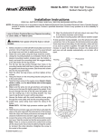
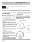
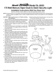
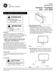
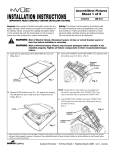
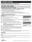
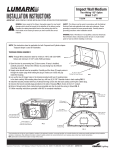
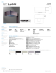
Tribute
Sheet 1 of 4
INSTALLATION INSTRUCTIONS
1/7/08
IMPORTANT : READ CAREFULLY BEFORE INSTALLING FIXTURE.
IMI-685
WARNING: Risk of Fire/Electric Shock. If not qualified, consult an electrician.
WARNING: Risk of Electric Shock. Disconnect power at fuse or circuit breaker before installing or servicing.
WARNING: Risk of Burn. Disconnect power and allow fixture to cool before changing bulb or handling fixture.
WARNING: Risk of Personal Injury. Fixture may become damaged and/or unstable if not installed properly.
Tighten all fixture components to their recommended torque values. Ensure door is properly latched.
WARNING: Risk of Fire/Electrical Shock. Upside down installation can result in overheating or accumulation of water in fixture. Install right side up.
Tools Required Socket, 5/16" Socket, 3/4" Deep Well Socket, Electrical
wiring tools.
FIG. 1
NOTE: these luminaires are designed for outdoor lighting
services, and should not be used in area of limited ventilation
or in high ambient temperature enclosures. Construction is
suitable for down lighting only. Best results will be obtained
if installed and maintained according to the following
recommendations.
Latch
1. Open housing door by squeezing thumb latch towards front of
housing. To relieve latch pressure, compress gasket by pushing
door into housing. Once the latch is disengaged, gently swing the door
open. FIG. 1
2. Remove the door by opening it to 45° angle “half open/half closed” then
lift it off the hook shaped hinges. FIG. 2
3. Remove the electrical compartment cover.
Hard Mount Version
• Hard mount electrical covers requires captive screws “1” & “2” to be
loosened. Grab handle and remove cover. FIG. 3a
Power Tray Version
• Power tray version requires captive screw “1” to be loosened. FIG. 3a
• Grab handle and open power tray. FIG. 3b
• To remove power tray from housing, unhook pin through gap in
power tray. Slide off of back pin and unplug the electrical
connection. FIG. 3c
FIG. 3b
FIG. 3a
Screw “1”
FIG. 2
Lift
Open
Power
Tray
FIG. 3c
Handle
Screw “2”
These instructions do not claim to cover all details or variations in the equipment, procedure, or process described, nor to provide directions for meeting every possible contingency
during installation, operation or maintenance. When additional information is desired to satisfy a problem not covered sufficiently for user’s purpose, please contact your nearest
representative.
NOTE: Specifications and dimensions subject to change without notice
Visit our web site at www.cooperlighting.com
Customer First Center 1121 Highway 74 South Peachtree City, GA 30269 770.486.4800 FAX 770.486.4801
ADH070937
Tribute
Sheet 2 of 4
INSTALLATION INSTRUCTIONS
1/7/08
IMPORTANT : READ CAREFULLY BEFORE INSTALLING FIXTURE.
IMI-685
Mounting the fixture
4a. Arm Mount (FIG. 4a)
• Arm Mounting (Square Pole) Lay the fixture on its’ top
with door removed. Remove pole cap allowing nut plate
to be inserted into pole and align with bolt holes. Install
threaded bolts into nut plate. Align arm (end with drain
holes towards pole) and place over threaded bolts.
Align holes in fixture with bolts. Route fixture supply leads
through arm and into pole. Inside of fixture place lock
washer and nuts onto threaded bolts, secure. Housing
and arm must be square with pole. Tighten bolts to 30 ft
lbs. Bolts must not be extended into fixture more than 1".
Finish securing electrical connections inside of pole.
FIG. 4a (Arm Mount)
Pole Cap
Nut Plate
Arm
Drain Hole
In This
Location
Hex Nut
Lock Washer
1/2-13 Threaded Rod.
Max. extension into housing
is 1”.
• Arm Mounting (Round Pole) Installation is the same as
square pole except a round pole adapter is used against
the round pole.
4b. Internal Mast Arm Mount (FIG. 4b)
• Loosen the four tenon clamp bolts for insertion of the
mounting tenon. Note: for the 2" pipe size tenon,
remove the tear away portion of the tenon entrance
gasket. To remove, grasp the aluminum gasket with
pliers and twist off the pre-cut portion of the gasket.
• Pull service lead wires through the mounting tenon until
about 6" extends beyond the tenon end.
• Slide the luminaire onto the tenon while guiding the
service lead wires. Make sure end of tenon is against
stop in housing.
• Tighten 4 tenon clamp bolts. Note: fixture can be
leveled by tightening front bolts differently than rear
bolts. When fixture is level, torque all 4 clamp bolts to
100 inch-pounds. Tighten bolts in alternating pattern.
• Connect service lead wires to fixture leads and anchor
leads in place so they are not in contact with the reflector
surface or ballast surface.
• Replace electrical compartment cover removed in
step 3.
Cross Sectional View of Fixture Mounted to Pole
FIG. 4b (Internal Mast Arm Mount)
2” or 1 1/2”
Mounting
Tenon
“A”
Service Lead Wires
Extend Min. 6”
Flip Clamps
over for 1 1/2” Pipe
Housing
Stop
Electrical
Cover
Detail “A”
Tear off this part
of gasket for
2” pipe size
Tenon Clamp Bolts (qty. 4)
Torque to 100 inch pounds
These instructions do not claim to cover all details or variations in the equipment, procedure, or process described, nor to provide directions for meeting every possible contingency
during installation, operation or maintenance. When additional information is desired to satisfy a problem not covered sufficiently for user’s purpose, please contact your nearest
representative.
NOTE: Specifications and dimensions subject to change without notice
Visit our web site at www.cooperlighting.com
Customer First Center 1121 Highway 74 South Peachtree City, GA 30269 770.486.4800 FAX 770.486.4801
ADH070937
Tribute
Sheet 3 of 4
INSTALLATION INSTRUCTIONS
1/7/08
IMPORTANT : READ CAREFULLY BEFORE INSTALLING FIXTURE.
4c. Slipfitter Mount (FIG. 4c)
• The integral slipfitter can be mounted on 2" (2 3/8"
O.D.) pipe. Set screws and a thru bolt are provided to
clamp it securely to the tenon. Thru bolt will require a
drilled hole thru the arm or tenon. Use the slipfitter as a
pattern to drill the thru hole. Secure electrical leads
from the drill path. Remove slipfitter and clean burrs on
tenon from drilled hole. Reinstall the slipfitter. Remove
the cover plate from slipfitter and bring leads into
compartment. Pull power supply leads and the ground
lead into the bottom half of the slipfitter. Be sure the
pivot retainer bolt is tightened securely after aiming is
accomplished. Tighten all mounting bolts per FIG. 4c.
4d. Trunnion Mount (FIG. 4d)
• If the unit is provided with a trunnion which can be
mounted directly on a flat surface (Adapters are
available for installation on building fronts, poles,
crossarms, pipes, etc.) 14-3 SO cable is
recommended for making electrical connection.
The fixture is provided with a grommnet and a strain
relief (approximately 9/16" diameter). To maintain the
seal, screws in the strain relief must be retightened
whenever the seal is disturbed.
5. Socket Setting Adjustment—Type II or Type III Only
(FIG. 5)
• Socket is normally factory set to provide IES Type II light
distribution pattern. To obtain IES Type III distribution,
proceed as follows (FIG. 5).
• Loosen the two (2) hex head clamping screws
sufficiently for the socket to clear the indexing screws.
• Move socket bracket so that the indexing screws
engage appropriate indexing holes. See table (FIG. 5)
for socket position and resulting light pattern.
IMI-685
FIG. 4c (Slipfitter Mount)
Pivot Retainer Bolt
Torque to 40-50
foot-pounds
Set screw
Torque to 15-20
foot-pounds
3/8-16 x 4”
Hex Head Thru Bolt
with lock nut.
FIG. 4d (Trunnion Mount)
3/8-16 Bolt
(Torque to 120-140
inch-pounds)
3 1/2"
[89mm]
3" [77mm]
2" [51mm]
5 3/8" [137mm]
Mounting
Holes
FIG. 5
Light Pattern
IES Type
II
III
Socket
Mount
Socket Index Position
250W Clear HPS Lamp
All other Clear
(5 3/4” LCL)*
HID Lamps (5” LCL)*
A
B
C
D
NOTE: * Light Center Length.
Indexing
Screw (2)
Indexing
Hole
Clamping
Screw (2)
These instructions do not claim to cover all details or variations in the equipment, procedure, or process described, nor to provide directions for meeting every possible contingency
during installation, operation or maintenance. When additional information is desired to satisfy a problem not covered sufficiently for user’s purpose, please contact your nearest
representative.
NOTE: Specifications and dimensions subject to change without notice
Visit our web site at www.cooperlighting.com
Customer First Center 1121 Highway 74 South Peachtree City, GA 30269 770.486.4800 FAX 770.486.4801
ADH070937
INSTALLATION INSTRUCTIONS
Tribute
Tribute
Sheet 4 of 4
Sheet 1 of 4
1/7/08
IMPORTANT: READ CAREFULLY BEFORE INSTALLING FIXTURE.
IMI-685
Tools Required Socket, 5/16" Socket, 3/4" Deep Well Socket, Electrical
wiring tools.
FIG. 6
FIG. 1
Latch
1. Open housing door by squeezing thumb latch towards front of
housing. To relieve latch pressure, compress gasket by pushing
door into housing. Once the latch is disengaged, gently swing the door
open. FIG. 1
8. Photocontrol Receptacle Loosen the two flathead screws to allow
rotation of the receptacle. Insert screwdriver into center slot and rotate
receptacle until indicator arrow points north. Retighten screws. Plug the
photoelectric control into receptacle and twist into locked position.
The photocontrol must contain a soft, resilient gasket fastened to the
bottom surface to assure a proper weather seal between the control
and the receptacle.
9. Lamp installation Open fixture door. Install the lamp by grasping it close
to the base and rotating clockwise, tightening securely to engage socket
center contact. Close the fixture door.
IMI-685
NOTE: these luminaires are designed for outdoor lighting
services, and should not be used in area of limited ventilation
or in high ambient temperature enclosures. Construction is
suitable for down lighting only. Best results will be obtained
if installed and maintained according to the following
recommendations.
Wire leads are to be routed from housing to pole. All wiring connections are
to be made in the pole. Wire the fixture voltage leads to the supply voltage
lead; fixture common lead to the supply neutral lead; and the fixture ground
lead to the supply ground lead. If fixture is supplied with the ballast tray
option, re-connect the polarized plug and replace the ballast tray.
NOTE: The orientation procedure is only required for photocontrols which
specifically require the cell to be aimed north. Otherwise factory orientation
will work. Follow the directions recommended by the supplier of the
photocontrol for proximity to light sources. Lighted signs, building surface
reflection, floodlights, tree branches, etc. May affect final position of the
photocontrol. FIG. 7
1/7/08
IMPORTANT : READ CAREFULLY BEFORE INSTALLING FIXTURE.
WARNING: Risk of Fire/Electric Shock. If not qualified, consult an electrician.
WARNING: Risk of Electric Shock. Disconnect power at fuse or circuit breaker before installing or servicing.
WARNING: Risk of Burn. Disconnect power and allow fixture to cool before changing bulb or handling fixture.
WARNING: Risk of Personal Injury. Fixture may become damaged and/or unstable if not installed properly.
Tighten all fixture components to their recommended torque values. Ensure door is properly latched.
WARNING: Risk of Fire/Electrical Shock. Upside down installation can result in overheating or accumulation of water in fixture. Install right side up.
6. Light Distribution Some of the reflector options are directional oriented.
The reflector can be rotated in 90° increments. Loosen reflector mounting
screws and rotate reflector to desired orientation and then retighten the
mounting screws. FIG. 6. Tools required 1/4" socket.
7. Wiring
Important: Dual voltage and multi-tap ballasts are factory-wired for
277V input. Before installation make certain supply and ballast voltages
are compatible. For use with other line voltages, remove wire nut
splicing the black lead from the quick disconnect plug and 277V lead
from ballast. Cap off 277V lead with wire nut. Splice black lead from
the quick disconnect plug with desired voltage lead from ballast.
INSTALLATION INSTRUCTIONS
2. Remove the door by opening it to 45° angle “half open/half closed” then
lift it off the hook shaped hinges. FIG. 2
3. Remove the electrical compartment cover.
Hard Mount Version
• Hard mount electrical covers requires captive screws “1” & “2” to be
loosened. Grab handle and remove cover. FIG. 3a
Power Tray Version
• Power tray version requires captive screw “1” to be loosened. FIG. 3a
• Grab handle and open power tray. FIG. 3b
• To remove power tray from housing, unhook pin through gap in
power tray. Slide off of back pin and unplug the electrical
connection. FIG. 3c
FIG. 7
Loosen
NOTE: Do not use lubricants on lamp base or socket as this will cause
damage and void warranty.
FIG. 3b
FIG. 3a
10. Reflector and Lens Cleaning Open fixture door, dust reflector with soft,
clean dry cloth. Do not use alkaline or acidic cleaners on reflector
surfaces. Clean lens with non-abrasive glass cleaning solution.
Screw “1”
FIG. 2
Lift
Open
Power
Tray
FIG. 3c
Handle
NOTE: A regular maintenance schedule should be followed to retain optimal
light output and reduce heat retention.
Screw “2”
These instructions do not claim to cover all details or variations in the equipment, procedure, or process described, nor to provide directions for meeting every possible contingency
during installation, operation or maintenance. When additional information is desired to satisfy a problem not covered sufficiently for user’s purpose, please contact your nearest
representative.
NOTE: Specifications and dimensions subject to change without notice.
Visit our web site at www.cooperlighting.com
Customer First Center 1121 Highway 74 South Peachtree City, GA 30269 770.486.4800 FAX 770.486.4801
ADH070937
NOTE: Specifications and dimensions subject to change without notice.
Visit our web site at www.cooperlighting.com
Customer First Center 1121 Highway 74 South Peachtree City, GA 30269 770.486.4800 FAX 770.486.4801
ADH070937