1
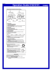
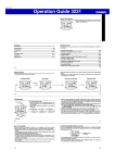
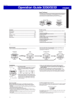
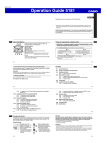
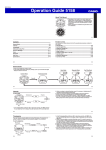
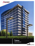
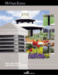
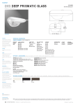
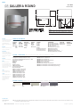
AREA
GR GALLERIA ROUND
250-1000W
MH/HPS/SMH
ARCHITECTURAL AREA LUMINAIRE
A
A
B
B
F
C
D
E
C
D
Fixture
250-400W (in.)
(mm)
1000W (in.)
(mm)
NOTE: In all flat glass configurations only.
A
18 1/4
464
19 3/4
502
B
3 1/2
89
4 1/4
108
C
19 3/4
502
25 5/8
651
D
24 1/2
676
32 15/16
837
E
6 or 14
152 or 356
6 or 14
152 or 356
F
16
406
19 3/4
502
STREETWORKS™
HOUSING
Roll-formed aluminum housing with
stamped reveal has interior-welded
seams for structural integrity.
Optional NEMA twistlock
photocontrol. ANSI wattage/source
label.
BALLAST
Ballast is hard-mounted to housing
O R D E R I N G I N F O R M AT I O N
SAMPLE NUMBER: GRA25MWWXX
PRODUCT
FAMILY 1
GRA=Arm
GRC=Spider
2 3/8" 3" O.D.
LAMP
WATTAGE
25=250W
40=400W
91=1000W
LAMP TYPE 2
S=High Pressure
Sodium
M=Metal
Halide
R=SMH
BALLAST
TYPE 2
W=CWA
C=CWI
M=Mag. Reg.
interior for cooler operation.
VOLTAGE 2
2=120V
0=208V
4=240V
7=277V
8=480V
W=Multi-Tap wired 120V
N=Multi-Tap wired 277V
V=Multi-Tap wired 240V
REFLECTOR
DISTRIBUTION
LENS TYPE
OPTIONS +
1D=Type I MCO (Horizontal)
FG=Flat Glass 3, 5 ACCESSORIES
2D=Type II MCO (Horizontal) SG=Sag Glass
(See Below)
3D=Type III MCO (Horizontal)
3V=Type III (Vertical)
FT=Forward Throw (Horizontal)
AR=Area Round (Vertical)
AS=Area Square (Vertical)
RW=Rectangular Wide (Vertical)
SL=Spill Light Eliminator (Horizontal) 3, 4
Spun and stamped anodized
aluminum reflector in vertical lamp
units, or hydroformed anodized
OPTIONS + ACCESSORIES [Must be listed in the order shown and separated by a dash]
aluminum reflector in horizontal
lamp units.
SPRINGS
Aluminum door retaining springs.
DOOR
Formed aluminum door for
arm-mount fixture has retaining
springs, while spider-mount unit
has a heavy-duty hinge and captive
retaining screws. Door is finished in
polyester powder coat.
LENS
Convex tempered glass lens.
Tempered flat glass available.
FINISH
Standard polyester powder coat
finish in bronze. For more color
options see optional colors or
consult your Streetworks
OPTIONS (add as suffix)
1=Single Fuse, Internally Mounted (120 or 277)
2=Double Fuse, Internally Mounted (208, 240, or 480V)
4=Photocontrol Receptacle
WH=White
BK=Black
AP=Grey
DP=Dark Platinum
GM=Graphit Metallic
H=Plug-in Starter Receptacle 4
B=House Side Shield
AIR=Arm Included for Round Pole 6
AIS=Arm Included for Square Pole 6
CSR=Color Reveal Stripe—Red
CSB=Color Reveal Stripe—Blue
CSY=Color Reveal Stripe—Yellow
CSG=Color Reveal Stripe—Green
CSD=Color Reveal Stripe—Gold
CSS=Color Reveal Stripe—Silver
CSW=Color Reveal Stripe—White
ACCESSORIES (order separately)
MA1025=14" Arm for Square Pole 7
MA1026=6" Arm for Square Pole
MA1006=Direct Mounting Kit for Square Pole
MA1027=14" Arm for Round Pole 7
MA1028=6" Arm for Round Pole
MA1009=Direct Mounting Kit for Round Pole
MA1061 =House Side Shield—Field Installed (Medium Housing)
MA1062 =House Side Shield—Field Installed (Large Housing)
represenatitive for more
information.
OPTIONAL COLORS [Standard color is bronze, other finish colors available. Consult your Cooper Lighting representative]
WH
White
BK
Black
AP
Grey
DP
Dark Platinum
GM
Graphite Metallic
S H I P P I N G D ATA
Approximate Net Weight:
86 lbs. (40 kgs.)
NOTE: 1 Order arm separately. 2 Refer to technical section for lamp/ballast/voltage compatibility. 3 Must use reduced envelop lamp. 4 Not available in 1000W. 5 Available in 1D, 2D, 3D, FT. AR. 6 Arm length varies based on housing
size. 7 Required for mounting fixtures at 90° increments.
84 S T R E E T W O R K S O u t d o o r L i g h t i n g S o l u t i o n s
Cooper Lighting
GR GALLERIA ROUND AREA
P H O T O M E T R I C S [ C o m p l e t e I E S f i l e s a v a i l a b l e a t w w w. c o o p e r l i g h t i n g . c o m ]
5
5
4
4
E
3
C
2
A
1
AB C
6
5
4
3
2
1
0
1
2
3
3
D
2
B
1
D E
4
5
6
0
0
1
1
2
2
3
3
4
4
5
6
GRA91SARS.IES
1000-Watt HPS
140,000-Lumen Lamp
Area Round Sag Glass
5
4
3
2
1
0
1
2
3
4
5
6
5
G R A 9 1 M 3 D F. I E S
1000-Watt MH
110,000-Lumen Lamp
Type III MCO Flat Glass
F O O T C A N D L E TA B L E
Select mounting height and read across for footcandle values of
each isofootcandle line. Distance in units of mounting height.
Mounting
Footcandle Values for
Height
Isofootcandle Lines
A
B
C
D
E
GRA91SARS.IES
30'
3.54
2.66
1.77
0.88
0.44
35'
2.60
1.95
1.30
0.65
0.32
40'
2.00
1.50
1.00
0.50
0.25
45'
1.58
1.18
0.79
0.39
0.19
50'
1.28
0.96
0.64
0.32
0.16
GRA91M3DF.IES
30'
35'
40'
45'
50'
3.54
2.60
2.00
1.58
1.28
2.66
1.95
1.50
1.18
0.96
1.77
1.30
1.00
0.79
0.64
0.88
0.65
0.50
0.39
0.32
0.44
0.32
0.25
0.19
0.16
M O U N T I N G C O N F I G U R AT I O N S
Spider Mount
Arm Mount 2 @ 180°
Arm Mount Single
Arm Mount 2 @ 90°
Arm Mount 3 @ 90°
(Requires 14” Arm)
Arm Mount 3 @ 120°
(Requires 14” Arm)
Round Pole Only
Arm Mount 4 @ 90°
(Requires 14” Arm)
E.P.A. TABLE
DRILL PATTERN
SINGLE
[W/Arm where applicable]
2 @ 180°
2 @ 90°
3 @ 90°
3 @ 120°
“M” 1
2.2
4.4
5.4
7.1
7.1
7.9
3"
2.0
n/a
n/a
n/a
n/a
n/a
“M” 1
3.0
6.0
7.0
9.5
9.5
10.7
3"
2.8
n/a
n/a
n/a
n/a
n/a
GRA [Arm Mount] 250-400W
GRC [Spider Mount] 250-400W
GRA [Arm Mount] 1000W
GRC [Spider Mount] 1000W
4 @ 90°
NOTE: 1 Assumes 14" arm for 90° and 120° mounting configurations, 6" for all else.
D R I L L I N G PAT T E R N
2" OR 3" DIRECT MOUNT TENON ADAPTER
TYPE “M”
Top Cap
2 11/16''
[69mm]
3/4'' [20mm]
dia. hole
2 7/16'' [124mm]
4 7/8'' [124mm]
(2) 5/8'' [16mm]
dia. holes
12''
[305mm]
Set
Screws
(“M” Drilling for Arm Mounting)
Cooper Lighting
O R D E R I N G I N F O R M AT I O N
Catalog
Number
MA1010
MA1011
MA1012
MA1013
MA1014
MA1015
MA1016
MA1017
MA1018
Tenon
Size (In.)
3 1/2 O.D
3 1/2 O.D
3 1/2 O.D
3 1/2 O.D
3 1/2 O.D.
3 1/2 O.D
3 1/2 O.D
2 3/8 O.D
2 3/8 O.D
Fixture
Configuration
1 Fixture
2 Fixtures at 180°
3 Fixtures at 120°
4 Fixtures at 90°
2 Fixtures at 90°
2 Fixtures at 120°
3 Fixtures at 90°
1 Fixture
2 Fixtures at 180°
NOTES: Fitters for other tenon sizes available. Consult your Streetworks representative. Tenon adapter for through
bolt mounted luminaires. Standard adapter is bronze painted steel.
STREETWORKS Outdoor Lighting Solutions
85