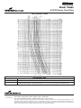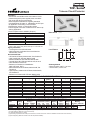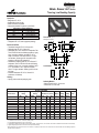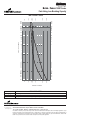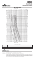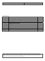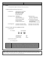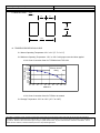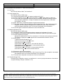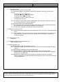
1
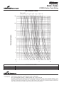
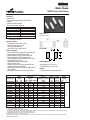
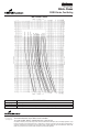
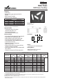
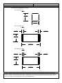
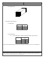
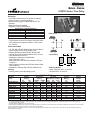
Brick™ Fuses
6125TD Series, Time Delay
Description
• Time Delay surface mount fuse capable of replacing
glass tube fuses in certain applications
• Environmentally rugged, complies with EIA-IS-722
Standard
• Solder Immersion Compatible
• Targeted for Consumer Electronics
ELECTRICAL CHARACTERISTICS
% of Amp Rating
Opening Time
100%
4 Hours Minimum
200%
1 Second Minimum
200%
2-4 Seconds Typical
200%
60 Seconds Maximum
Agency Information
• UL Recognition Guide & File numbers: JDYX2 & E19180.
• CSA Component Acceptance: 053787 C 000 & Class
No: 1422 30.
Environmental Data
• Life Test: MIL-STD-202, Method 108A, Test Condition D
• Load Humidity: MIL-STD-202, Method 103B
• Moisture Resistance: MIL-STD-202, Method 106E
• Thermal Shock: MIL-STD-202, Method 107D, air-to-air
• Case Resistance: EIA/IS-722
• Resistance to Dissolution of Metallization:
ANSI J-STD-002, Test D
• Mechanical Shock: MIL-STD-202, Method 213B, Test
Condition A
• High Frequency Vibration: MIL-STD-202, Method 204D,
Test Condition D
• Resistance to Solvents: MIL-STD-202, Method 215A
Ordering
• Specify product code and packaging code
Dimensions
mm
⁄(inches)
Land Pattern
2.6
3.0
(0.102)
(0.118)
4.0
(0.157)
8.6
(0.338)
Soldering Method
• Wave Immersion: 260°C, 3 sec max.
• Infrared: 260°C, 30 sec max.
SPECIFICATIONS
Product
Code
6125TD500mA
6125TD750mA
6125TD1A
6125TD1.5A
6125TD2A
6125TD2.5A
6125TD3A
6125TD3.5A
6125TD4A
6125TD5A
6125TD7A
Voltage
Rating
AC
DC
125V
60V
125V
60V
125V
60V
125V
60V
125V
60V
125V
60V
125V
60V
125V
60V
125V
60V
125V
60V
125V
60V
Interrupting
Rating*
125VAC 60VDC
50A
50A
50A
50A
50A
50A
50A
50A
50A
50A
50A
50A
50A
50A
50A
50A
50A
50A
50A
50A
50A
50A
DC Cold
Resistance** (ohms)
min. typ. max.
.3350 .4025 .4700
.2000 .2350 .2700
.1350 .1680 .2000
.0550 .0630 .0700
.0380 .0480 .0580
.0280 .0350 .0420
.0225 .0263 .0300
.0170 .0195 .0220
.0160 .0185 .0210
.0115 .0133 .0150
.0073 .0087 .0100
Typical
Melting
I2t†
0.716
1.07
2.88
2.35
9.45
16.2
15.3
14.5
38.8
34.4
90.2
Typical
Voltage
Drop‡
245 mV
250 mV
256 mV
125 mV
133 mV
130 mV
97 mV
95 mV
106 mV
100 mV
99 mV
* AC Interrupting Rating (Measured at designated voltage, 100% power factor); DC Interrupting Rating (Measured at designated voltage, time constant of less than
50 microseconds, battery source)
** DC Cold Resistance (Measured at 10% of rated current)
† Typical Melting I2t (Measured with a battery bank at rated DC voltage, 10x-rated current (not to exceed IR), time constant of calibrated circuit less than 50 microseconds)
‡ Typical Voltage Drop (Measured at rated current after temperature stabilizes)
Device designed to carry rated current for four hours minimum. An operating current of 80% or less of rated current is recommended, with further derating required at
elevated ambient temperatures.
Brick™ Fuses
6125TD Series, Time Delay
TIME CURRENT CURVE
250mA and 375mA
to be determined
PACKAGING CODE
Packaging Code
SP2
TR1
OC-2530 Rev. M 5/03
© Cooper Electronic
Technologies 2003
Description
50 piece sample
Standard Package: (This is an insert)
1000 pieces of fuses on 12mm tape-and-reel on a 7 inch (177mm) reel per EIA Standard 481
Visit us on the Web at www.cooperET.com
3601 Quantum Boulevard Boynton Beach, Florida 33426-8638
Tel: +1-561-752-5000 Toll Free: +1-888-414-2645 Fax: +1-561-742-1178
This bulletin is intended to present product design solutions and technical information that will help the end user with design applications. Cooper
Electronic Technologies reserves the right, without notice, to change design or construction of any products and to discontinue or limit distribution of
any products. Cooper Electronic Technologies also reserves the right to change or update, without notice, any technical information contained in this
bulletin. Once a product has been selected, it should be tested by the user in all possible applications.
TCP™ Series
Telecom Circuit Protector
Description
• The first and most reliable surface mount telecom circuit
protector designed to protect against power cross faults
and comply with all surge requirements.
• Allows compliance with telecom regulatory standards
including Bellcore GR 1089, UL 1950/60950, and FCC part
68. Application circuit testing is recommended.
• Eliminates the need for a current limiting resistor.
• Protects against overcurrent conditions found in telecom tip
and ring applications.
• RoHS Compliant version available (-R option)
ELECTRICAL CHARACTERISTICS
% of Amp Rating
Opening Time
100%
4 Hours Minimum
250%
1 Second Minimum
250%
4-10 Seconds Typical
250%*
120 Seconds Maximum
300%
10 Seconds Maximum
Dimensions
mm
⁄(inches)
* If the device does not open at 250% within 120 seconds, increase
current to 300% of amp rating. Device must open in 10 seconds max.
Agency Information
• UL Recognition Card: JDYX2/E19180
• CSA Component Certification Record and Class No.:
053787C000, 1422 30
Environmental Data
• Life Test: MIL-STD-202, Method 108A, Test Condition D
• Load Humidity: MIL-STD-202, Method 103B
• Moisture Resistance: MIL-STD-202, Method 106E
• Thermal Shock: MIL-STD-202, Method 107D, air-to-air
• Case Resistance: EIA/IS-722
• Resistance to Dissolution of Metallization:
ANSI J-STD-002, Test D
• Mechanical Shock: MIL-STD-202, Method 213B, Test
Condition A
• High Frequency Vibration: MIL-STD-202, Method 204D,
Test Condition D
• Resistance to Solvents: MIL-STD-202, Method 215A
Land Pattern
5.2
3.7
(0.204)
(0.145)
4.0
(0.157)
12.6
(0.496)
Soldering Method
• Wave Immersion: 260°C, 3 sec max.
• Infrared: 240°C, 30 sec max.
LIGHTNING SURGE SPECIFICATIONS
Surge Specification
Surge
FCC 47 Part 68
FCC 47 Part 68
Surge out
Longitudinal Type B
Metallic Type A
FCC 47 Part 68
FCC 47 Part 68
Bellcore GR-1089-CORE
Bellcore GR-1089-CORE
Surge out
Surge out
Longitudinal Type A
Metallic Type B
First Level Lightning
First Level Lightning
Repetitions
Waveform
(µSec.)
Current (A)
Voltage (V)
Performance
Requirement
N/A
800
N/A
Fuse cannot open
Fuse must open safely
Fuse cannot open
TCP 500mA tested
2
5x320
37.5
2
10x560
100
25
10x160
65
TCP 1.25A and TCP2A tested
2
10x160
100 per fuse
2
10x560
100
50
10x1000
100
50
2x10
500
1
10x160
160
1
10x560
115
1500
800
1000
2500
N/A
N/A
Fuse
Fuse
Fuse
Fuse
Fuse
Fuse
cannot
cannot
cannot
cannot
cannot
cannot
open
open
open
open
open
open
ELECTRICAL AND POWER CROSS SPECIFICATIONS
Product
Code
TCP500mA
TCP1.25A
TCP2A
Voltage
Rating
AC
250 V
250 V
250 V
Interrupting
Rating*
250VAC 600VAC
50 A
40 A
50 A
60 A
50 A
60 A
DC Cold
Resistance** (ohms)
min. typ. max.
0.420 0.530 0.640
0.070 0.090 0.110
0.050 0.075 0.100
Typical
Melting
I2t†
1.3 A2s
22.2 A2s
30 A2s
Maximum
Total
Clearing
100 A2s
100 A2s
100 A2s
Typical
Voltage
Drop‡
471mV
150mV
205mV
* AC Interrupting Rating (Measured at designated voltage, 100% power factor)
** DC Cold Resistance (Measured at 10% of rated current)
*** On RoHS Compliant Version (-R option)
† Typical Melting I2t (Measured with a battery bank at 60V DC, 10x-rated current, time constant of calibrated circuit less than 50 microseconds)
‡ Typical Voltage Drop (Measured at rated current after temperature stabilizes)
Alpha Code
Marking
1st Code 2nd Code
F
R***
J
N
TCP™ Series
Telecom Circuit Protector
TIME CURRENT CURVE
OPTIONS
Option Code (Suffix)
-R
Description
RoHS Compliant Version (Sn plating w/ Ni barrier)
PACKAGING CODE
Packaging Code
TR2
Visit us on the web at:
www.CooperET.com
Datasheet: 98076
6/15/04 - SB04124
© Cooper Electronic
Technologies 2004
Description
2500 pieces of fuses on 24mm tape-and-reel on 13 inch (330mm) reel per EIA Standard 481, 8mm pitch
North America
Cooper Bussmann
Cooper Electronic Technologies
P.O. Box 14460
3601 Quantum Boulevard
St. Louis, MO 63178-4460
Boynton Beach, FL 33426-8638
Tel: 1-636-394-2877
Tel: 1-561-752-5000
Fax: 1-800-544-2570
Fax: 1-561-742-0134
Toll Free: 1-888-414-2645
Europe
Cooper Electronic Technologies
Cooper (UK) Limited
Burton-on-the-Wolds
Leicestershire • LE12 5TH UK
Tel: +44 (0) 1509 882 737
Fax: +44 (0) 1509 882 786
Asia Pacific
Cooper Electronic Technologies
1 Jalan Kilang Timor
#06-01 Pacific Tech Centre
Singapore 159303
Tel: +65 278 6151
Fax: +65 270 4160
Brick™ Fuses 1025T Series
Time Lag, Low Breaking Capacity
Description
• Designed to IEC 127-4
• Surface Mount fuse, time lag
• Solder Immersion Compatible
• Overcurrent protection of systems up to 250VAC
ELECTRICAL CHARACTERISTICS
% of Amp Rating
Opening Time
125%
1 Hours Minimum
200%
2 Minutes Maximum
200%
1 Second Minimum
1000%
0.01 -- 0.1 Seconds
Approvals
• Designed to IEC 127, Sheet 4 (approval pending)
Environmental Data
• Termination Strength: IEC 127-4 Clause 8.3.2
• Soldered Joints: IEC 127-1 Clause 8.5
• Solderability: IEC 127-4 Clause 8.6.2 subjected to Test
Td of IEC-68-2-58 with the following conditions; Aging:
none. Immersion conditions: exceeds IEC 127-4.
Depth of immersion: entire metal surface. Flux type:
non-activated. Solder type: 60% tin and 40% lead
according to IEC 68-2-20, Appendix B.
• Resistance to Soldering Heat: IEC 127-4 Clause 8.7
subjected to Test Td of IEC 68-2-58 with the following
conditions; Aging: none. Immersion conditions: 260°C
± 5°C, 10 seconds ± 1 sec. Depth of immersion:
10mm. Flux type: activated. Solder type: 60% tin and
40% lead
• Insulation Resistance: IEC 127-4, Clause 9.3.3
(resistance ≥ 0.1Mohms)
Ordering
• Specify product code and packaging code
Dimensions
mm
⁄(inches)
Drawing Not to Scale
3.07 ± 0.15
(0.121 ± 0.006)
2.77 ± 0.15
3.07 ± 0.15
(0.109 ± 0.006)
(0.121 ± 0.006)
2.77 ± 0.15
(0.109 ± 0.006)
End View
1.4 ± 0.25
(0.055 ± 0.010)
1.4 ± 0.25
(0.055 ± 0.010)
3.07 ± 0.15
(0.121 ± 0.006)
10.29 ± 0.20
(0.405 ± 0.008)
2.77 ± 0.15
(0.109 ± 0.006)
1.4 ± 0.25
(0.055 ± 0.010)
1.4 ± 0.25
(0.055 ± 0.010)
2.77 ± 0.15
(0.109 ± 0.006)
3.07 ± 0.15
(0.121 ± 0.006)
Side View
10.29 ± 0.20
(0.405 ± 0.008)
Land Pattern
Top View
3.30
(0.130)
4.38
(0.172)
6.79
(0.267)
Soldering Method
• Wave Immersion: 260°C, 10 sec max.
• Infrared: 260°C, 30 sec max.
SPECIFICATIONS
Product Code
1025T250mA
1025T500mA
1025T800mA
1025T1A
1025T1.6A
1025T2A
1025T2.5A
1025T3.15A
1025T4A
1025T5A
1025T6.3A
Voltage
Rating
AC
DC
250V
125V
250V
125V
250V
125V
250V
125V
250V
125V
250V
125V
250V
125V
250V
125V
250V
125V
250V
125V
250V
125V
Interrupting
Rating*
250VAC 125VDC
100A
50A
100A
50A
100A
50A
100A
50A
100A
50A
100A
50A
100A
50A
100A
50A
100A
50A
100A
50A
100A
50A
DC Cold
Resistance** (ohms)
min. typ. max.
TBD
TBD TBD
TBD
TBD TBD
TBD
TBD TBD
TBD
TBD TBD
0.064 0.074 0.083
TBD
TBD TBD
0.045 0.048 0.051
0.030 0.034 0.038
TBD
TBD TBD
TBD
TBD TBD
TBD
TBD TBD
Typical Typical
Melting Voltage
I2t†
Drop‡
TBD
TBD
TBD
TBD
TBD
TBD
TBD
TBD
12.26 155 mV
TBD
TBD
32.91
TBD
54.98 184 mV
TBD
TBD
TBD
TBD
TBD
TBD
Max. Marking
Voltage Code
Drop‡
800
Dt
600
Ft
400
KKt
300
Ht
300
MMt
300
Nt
300
Ot
300
Qt
300
St
300
Tt
300
OOt
* AC Interrupting Rating (Measured at designated voltage, greater than 95% power factor); DC Interrupting Rating (Measured at designated voltage, time constant of
the calibrated circuit is less than 1 millisecond, battery source)
** DC Cold Resistance (Measured at ≤10% of rated current)
† Typical Melting I2t (Measured with a battery bank at rated DC voltage, 10x-rated current, not to exceed IR, time constant of calibrated circuit less than 50 microseconds)
‡ Typical Voltage Drop (Measured at rated current after temperature stabilizes)
• Device designed to carry rated current for four hours minimum. An operating current of 80% or less of rated current is recommended, with further derating required at
elevated ambient temperatures.
Brick™ Fuses 1025T Series
Time Lag, Low Breaking Capacity
TIME CURRENT CURVE
PACKAGING CODE
Packaging Code
TR2
TR3
OC-2536 Rev. XF 5/03
© Cooper Electronic
Technologies 2003
Description
2,500 pieces of fuses on 24mm tape-and-reel on 13 inch (330mm) reel per EIA Standard 481
50 pieces of fuses on 24mm tape packaged in a plastic box per EIA Standard 481
Visit us on the Web at www.cooperET.com
3601 Quantum Boulevard Boynton Beach, Florida 33426-8638
Tel: +1-561-752-5000 Toll Free: +1-888-414-2645 Fax: +1-561-742-1178
This bulletin is intended to present product design solutions and technical information that will help the end user with design applications. Cooper
Electronic Technologies reserves the right, without notice, to change design or construction of any products and to discontinue or limit distribution of
any products. Cooper Electronic Technologies also reserves the right to change or update, without notice, any technical information contained in this
bulletin. Once a product has been selected, it should be tested by the user in all possible applications.
Brick™ Fuses 1025F Series
Fast Acting, Low Breaking Capacity
Description
• Surface mount fuse, fast acting
• Designed to IEC 127-4
• Surface Mount
• Solder Immersion Compatible
• Overcurrent protection of systems up to 250 VAC
ELECTRICAL CHARACTERISTICS
% of Amp Rating
Opening Time
125%
1 Hour Minimum
200%
2 Minutes Maximum
1000%
0.001 - 0.01 Seconds
Approvals
• Designed to IEC 127, Sheet 4 (approval pending)
Environmental Data
• Termination Strength: IEC 127-4 Clause 8.3.2
• Soldered Joints: IEC 127-1 Clause 8.5
• Solderability: IEC 127-4 Clause 8.6.2
• Resistance to Soldering Heat: IEC 127-4 Clause 8.7
• Insulation Resistance: IEC 127-4 Clause 9.3.3
Soldering Method
• Wave Immersion: 260°C, 10 sec max.
• Infrared: 260°C, 30 sec max.
Ordering
• Specify product code and packaging code
Dimensions
mm
⁄(inches)
Drawing Not to Scale
2.77 ± 0.15
(0.109 ± 0 .006)
End View
1.4 ± 0.25
(0.055 ± 0.010)
1.4 ± 0.25
(0.055 ± 0.010)
3.07 ± 0.15
(0.121 ± 0.006)
3.07 ± 0.15
(0.121 ± 0.006)
2.77 ± 0.15
(0.109± 0.006)
3.07± 0.15
(0.121± 0.006)
10.29± 0.20
(0.405± 0.008)
2.77 ± 0.15
(0.109 ± 0 .006)
1.4 ± 0.25
(0.055 ± 0.010)
1.4 ± 0.25
(0.055 ± 0.010)
2.77 ± 0.15
(0.109 ± 0 .006)
3.07 ± 0.15
(0.121 ± 0 .006)
Side View
10.29 ± 0.20
(0.405 ± 0 .008)
Land Pattern
Top View
3.30
(0.130)
4.38
(0.172)
6.79
(0.267)
SPECIFICATIONS
Product Code
1025F250mA
1025F500mA
1025F800mA
1025F1A
1025F1.6A
1025F2A
1025F2.5A
1025F3.15A
1025F4A
1025F5A
1025F6.3A
Voltage
Rating
AC
DC
250V
125V
250V
125V
250V
125V
250V
125V
250V
125V
250V
125V
250V
125V
250V
125V
250V
125V
250V
125V
250V
125V
Interrupting
Rating*
250VAC 125VDC
100A
50A
100A
50A
100A
50A
100A
50A
100A
50A
100A
50A
100A
50A
100A
50A
100A
50A
100A
50A
100A
50A
DC Cold
Resistance** (ohms)
min. typ. max.
TBD TBD TBD
TBD TBD TBD
TBD TBD TBD
TBD TBD TBD
TBD TBD TBD
TBD TBD TBD
TBD TBD TBD
TBD TBD TBD
TBD TBD TBD
TBD TBD TBD
TBD TBD TBD
Typical
Melting
I2t†
TBD
TBD
TBD
TBD
TBD
TBD
TBD
TBD
TBD
TBD
TBD
Typical
Voltage
Drop‡
TBD
TBD
TBD
TBD
TBD
TBD
TBD
TBD
TBD
TBD
TBD
* AC Interrupting Rating (Measured at designated voltage, greater than 95% power factor); DC Interrupting Rating (Measured at designated voltage,
time constant of the calibrated circuit is less than 1 millisecond, battery source)
** DC Cold Resistance (Measured at ≤10% of rated current)
† Typical Melting I2t (Measured with a battery bank at 10x-rated current, not to exceed IR,
time constant of calibrated circuit less than 50 microseconds)
‡ Typical Voltage Drop (Measured at rated current after temperature stabilizes)
• Device designed to carry rated current for four hours minimum. An operating current of 80% or less of rated current is recommended, with
further derating required at elevated ambient temperatures.
Marking
Code
Df
Ff
KK f
Hf
MM f
Nf
Of
Qf
Sf
Tf
OO f
Brick™ Fuses 1025F Series
Fast Acting, Low Breaking Capacity
2000 %
1000 %
300 %
166 %
200 %
100 %
4000
3000
4000
3000
2000
2000
1000
800
600
500
400
300
1000
800
600
500
400
300
200
200
100
80
60
50
40
30
100
80
60
50
40
30
20
20
10
8
6
5
4
3
10
8
6
5
4
3
2
2
1
.8
.6
.5
.4
.3
1
.8
.6
.5
.4
.3
.2
.2
.1
.08
.06
.05
.04
.03
.1
.08
.06
.05
.04
.03
.02
.02
2000 %
.001
1000 %
.001
300 %
.002
200 %
.002
166 %
.01
.008
.006
.005
.004
.003
100 %
.01
.1
.008
.006
.005
.004
.003
50 %
TIME IN SECONDS
50 %
TIME CURRENT CURVE
CURRENT IN PERCENT
PACKAGING CODE
Packaging Code
TR2
TR3
OC-2548 Rev. X2 5/03
© Cooper Electronic
Technologies 2003
Description
2500 pieces of fuses on 24mm tape-and-reel on a 13 inch (330mm) reel per EIA Standard 481
50 pieces of fuses on 24mm tape packaged in a plastic box per EIA Standard 481
Visit us on the Web at www.cooperET.com
3601 Quantum Boulevard Boynton Beach, Florida 33426-8638
Tel: +1-561-752-5000 Toll Free: +1-888-414-2645 Fax: +1-561-742-1178
This bulletin is intended to present product design solutions and technical information that will help the end user with design applications. Cooper
Electronic Technologies reserves the right, without notice, to change design or construction of any products and to discontinue or limit distribution of
any products. Cooper Electronic Technologies also reserves the right to change or update, without notice, any technical information contained in this
bulletin. Once a product has been selected, it should be tested by the user in all possible applications.
Brick™ Fuses
6125FA Series, Fast Acting
Description
• Surface Mount
• Environmentally rugged, complies with the EIA-IS-722
Standard
• Solder Immersion Compatible
• Targeted for Consumer Electronics
• Overcurrent protection of systems up to 125VAC/DC
• Wire-in-air design
ELECTRICAL CHARACTERISTICS
% of Amp Rating
Opening Time
100%
4 Hours Minimum
200%
5 Seconds Maximum
Agency Information
• UL Listed Guide and File Numbers (250mA-12A):
JDYX & E195337
• UL Recognized Guide and File Numbers (15A):
JDYX2 & E195337
• CSA Component Acceptance: 053787 C 000 &
Class No: 1422 30
Environmental Data
• Shock: MIL-STD-202, Method 213, Test Condition 1
(100 G’s peak for 6 milliseconds)
• Vibration: MIL-STD-202, Method 201 (10-55 Hz, 0.06
inch, total excursion)
• Salt Spray: MIL-STD-202, Method 101, Test Condition
B (48 hrs)
• Insulation Resistance: MIL-STD-202, Method 302, Test
Condition A (After Opening) 10,000 ohms minimum
• Resistance to Solder Heat: MIL-STD-202, Method 210,
Test Condition F (20 sec, at 260° C)
• Thermal Shock: MIL-STD-202, Method 107, Test
Condition B (-65° C to +125° C)
Ordering
• Specify product code and packaging code
Dimensions
mm
⁄(inches)
Drawing Not to Scale
2.59+ .250
(0.102+.010)
End View
1.35+.25
(0.053+.010)
1.35 +.25
(0.053+.010)
2.59+.25
(0.102+.010)
2.59+ .250
(0.102+.010)
Top View
6.10+.25
(0.240+.010)
1.35+ .25
(0.053+ .010)
1.35+.25
(0.053+.010)
2.59+ .25
(0.102+.010)
Side View
6.10+.25
(0.240+.010)
Land Pattern
2.6
3.0
(0.102)
(0.118)
4.0
(0.157)
8.6
(0.339)
Soldering Method
• Wave Solder: 260°C, 10 sec max.
(MIL-STD-202, Method 210)
• Infrared Reflow: 260°C, 30 sec max.
SPECIFICATIONS
Product
Code
6125FA250mA
6125FA375mA
6125FA500mA
6125FA750mA
6125FA1A
6125FA1.25A
6125FA1.5A
6125FA2A
6125FA2.5A
6125FA3A
6125FA3.5A
6125FA4A
6125FA5A
6125FA6.3A
6125FA7A
6125FA10A
6125FA12A
6125FA15A
AC
125V
125V
125V
125V
125V
125V
125V
125V
125V
125V
125V
125V
125V
125V
125V
125V
125V
N/A
Voltage
Rating
DC
125V
125V
125V
125V
125V
125V
125V
125V
125V
125V
125V
125V
125V
125V
125V
N/A
N/A
N/A
DC
86V
86V
86V
86V
86V
86V
86V
86V
86V
86V
86V
86V
86V
86V
86V
86V
86V
86V
Interrupting
Rating*
125V AC 125V DC 86V DC
50A
300A
10,000A
50A
300A
10,000A
50A
300A
10,000A
50A
300A
10,000A
50A
300A
10,000A
50A
300A
10,000A
50A
300A
10,000A
50A
300A
10,000A
50A
300A
10,000A
50A
300A
10,000A
50A
300A
10,000A
50A
300A
10,000A
50A
300A
10,000A
50A
300A
10,000A
50A
300A
10,000A
50A
N/A
10,000A
50A
N/A
10,000A
N/A
N/A
10,000A
Resistance
(ohms)**
Typ.
0.65
0.36
0.24
0.15
0.11
0.09
0.07
0.05
0.038
0.028
0.025
0.022
0.016
0.012
0.011
0.007
0.006
0.004
Typical
Melt
I2t†
0.01
0.03
0.06
0.07
0.14
0.24
0.41
0.80
1.4
2.4
3.3
4.4
7.8
14.0
19.0
44
69
124
Typical
Voltage
Drop (V)‡
0.30
0.25
0.22
0.17
0.17
0.16
0.15
0.15
0.14
0.13
0.13
0.13
0.12
0.12
0.114
0.107
0.103
0.098
* AC Interrupting Rating (Measured at designated voltage, 100% power factor); DC Interrupting Rating (Measured at designated voltage, time constant of less than 50
microseconds, battery source)
** DC Cold Resistance (Measured at 10% of rated current)
† Typical Melting I2t (Measured with a battery bank at rated DC voltage, 10x-rated current, time constant of calibrated circuit less than 50 microseconds)
‡ Typical Voltage Drop (Measured at rated current after temperature stabilizes)
Device designed to carry rated current for four hours minimum. An operating current of 80% or less of rated current is recommended, with further derating required at elevated
ambient temperatures.
Brick™ Fuses
6125FA Series, Fast Acting
TIME CURRENT CURVE
PACKAGING CODE
Packaging Code
SP2
TR2
OC-2531 Rev. I 5/03
© Cooper Electronic
Technologies 2003
Description
50 piece sample
5000 pieces of fuses on 12mm tape-and-reel on a 13 inch (330mm) reel per EIA Standard 481
Visit us on the Web at www.cooperET.com
3601 Quantum Boulevard Boynton Beach, Florida 33426-8638
Tel: +1-561-752-5000 Toll Free: +1-888-414-2645 Fax: +1-561-742-1178
This bulletin is intended to present product design solutions and technical information that will help the end user with design applications. Cooper
Electronic Technologies reserves the right, without notice, to change design or construction of any products and to discontinue or limit distribution of
any products. Cooper Electronic Technologies also reserves the right to change or update, without notice, any technical information contained in this
bulletin. Once a product has been selected, it should be tested by the user in all possible applications.
Brick™ Fuses
1025FA Series, Fast Acting
Description
• Surface Mount
• Environmentally rugged, satisfies the EIA/IS-722
Standard
• Solder Immersion Compatible
• Targeted for Consumer Electronics
ELECTRICAL CHARACTERISTICS
% of Amp Rating
Opening Time
100%
4 Hours Minimum
200% (250mA-5A)
5 Seconds Maximum
250% (250mA-5A fuse)
1 Second Maximum
200% (7A-15A fuse)
20 Seconds Maximum
250% (7A-15A fuse)
4 Seconds Maximum
Dimensions
mm
⁄(inches)
Drawing Not to Scale
Note: 30vde constant current source required for 200%
overload tests on 250ma-1a.
Agency Information
• UL Recognition Guide & File numbers:
JDYX2 & E19180 (250mA - 15A)
• CSA Component Acceptance:
File # 053787 C000, Class # 1422 30
Environmental Data
• Life Test: MIL-STD-202, Method 108A, Test Condition D
• Load Humidity: MIL-STD-202, Method 103B
• Moisture Resistance: MIL-STD-202, Method 106E
• Terminal Strength: MIL-STD-202, Method 211A
• Thermal Shock: MIL-STD-202, Method 107D, air-to-air
• Case Resistance: EIA/IS-722
• Resistance to Dissolution of Metallization:
ANSI J-STD-002, Test D
• Mechanical Shock: MIL-STD-202, Method 213B with
exceptions per EIA/IS-722 Standard
• High Frequency Vibration: MIL-STD-202, Method 204D,
Test Condition D
• Resistance to Solvents: MIL-STD-202, Method 215A
Land Pattern
3.30
(0.130)
4.38
(0.172)
6.79
(0.267)
Soldering Method
• Wave Solder: 260°C, 10 sec max.
• Infrared Reflow: 260°C, 30 sec max.
Ordering
• Specify product code and packaging code
SPECIFICATIONS
Product Code
1025FA250mA
1025FA500mA
1025FA750mA
1025FA1A
1025FA1.5A
1025FA2A
1025FA2.5A
1025FA3A
1025FA3.5A
1025FA4A
1025FA5A
1025FA7A
1025FA10A
1025FA12A
1025FA15A
Voltage
Rating
AC
DC
250V
125V
250V
125V
250V
125V
250V
125V
250V
125V
250V
125V
250V
125V
250V
125V
250V
125V
250V
125V
250V
125V
250V
60V
250V
60V
250V
60V
250V
60V
Interrupting
Rating*
250VAC 125VDC 60VDC
50A
50A
50A
50A
50A
50A
50A
50A
50A
50A
50A
50A
50A
50A
50A
50A
50A
50A
50A
50A
50A
50A
50A
50A
50A
50A
50A
50A
50A
50A
DC Cold
Resistance** (ohms)
Typical
5.0000
1.2000
0.6000
0.3000
0.1040
0.0800
0.0510
0.0390
0.0300
0.0270
0.0200
0.0116
0.0076
0.0550
0.0041
Typical
Melting
I2t†
0.1212
0.0415
0.143
1.750
1.460
6.086
8.48
18.15
17.83
23.32
38.74
138
457
498
1451
Typical
Marking
Voltage
Code‡‡
1st & 2nd
3rd
Drop‡
2019 mV
AD
1500 mV
AF
880 mV
AG
560 mV
AH
260 mV
AK
258 mV
AN
U,
232 mV
AO
T
205 mV
AP
or
185 mV
AR
S
190 mV
AS
180 mV
AT
150 mV
AU
146 mV
AW
120 mV
AX
110 mV
AY
* AC Interrupting Rating (Measured at designated voltage, 100% power factor random closing); DC Interrupting Rating (Measured at designated voltage, time constant of
less than 50 microseconds, battery source)
** DC Cold Resistance (Measured at ≤10% of rated current)
† Typical Melting I2t (Measured with a battery bank at rated DC voltage, 10x-rated current, but not exceeding the interrupting rating. Time constant of calibrated circuit less
than 50 microseconds). Test current not to exceed interrupting rating of 50A.
‡ Typical Voltage Drop (Measured at rated current after temperature stabilizes)
‡‡ Marking Code - 3rd (U = USA, T = Taiwan and S = China)
• Device designed to carry rated current for four hours minimum. An operating current of 80% or less of rated current is recommended, with further derating required at
elevated ambient temperatures.
Brick™ Fuses
1025FA Series, Fast Acting
TIME CURRENT CURVE
PACKAGING CODE
Packaging Code
SP1
TR2
OC-2538 Rev. X6 5/03
© Cooper Electronic
Technologies 2003
Description
50 piece sample
2,500 pieces of fuses on 24mm tape-and-reel on 13 inch (330mm) reel per EIA Standard 481
Visit us on the Web at www.cooperET.com
3601 Quantum Boulevard Boynton Beach, Florida 33426-8638
Tel: +1-561-752-5000 Toll Free: +1-888-414-2645 Fax: +1-561-742-1178
This bulletin is intended to present product design solutions and technical information that will help the end user with design applications. Cooper
Electronic Technologies reserves the right, without notice, to change design or construction of any products and to discontinue or limit distribution of
any products. Cooper Electronic Technologies also reserves the right to change or update, without notice, any technical information contained in this
bulletin. Once a product has been selected, it should be tested by the user in all possible applications.
Brick™ Fuses
1025TD Series, Time Delay
Description
• Surface Mount
• Environmentally rugged, satisfies the EIA/IS-722
Standard
• Solder Immersion Compatible
• Targeted for Consumer Electronics
ELECTRICAL CHARACTERISTICS
% of Amp Rating
Opening Time
100%
4 Hours Minimum
200%
1 Second Minimum
200%
60 Seconds Maximum
250% *
10 Seconds Maximum
Dimensions
mm
⁄(inches)
Drawing Not to Scale
* If fuse does not open @ 200% in 60 seconds, raise current to 250%
and the fuse must open in 10 seconds maximum.
Agency Information
• UL Recognition Guide & File numbers:
JDYX2 & E19180 (250mA - 5A)
• CSA Component Acceptance:
File # 053787 C000, Class # 1422 30
Environmental Data
• Life Test: MIL-STD-202, Method 108A, Test Condition D
• Load Humidity: MIL-STD-202, Method 103B
• Moisture Resistance: MIL-STD-202, Method 106E
• Terminal Strength: MIL-STD-202, Method 211A
• Thermal Shock: MIL-STD-202, Method 107D, air-to-air
• Case Resistance: EIA/IS-722
• Resistance to Dissolution of Metallization:
ANSI J-STD-002, Test D
• Mechanical Shock: MIL-STD-202, Method 213B with
exceptions per EIA/IS-722 Standard
• High Frequency Vibration: MIL-STD-202, Method 204D,
Test Condition D
• Resistance to Solvents: MIL-STD-202, Method 215A
Land Pattern
3.30
(0.130)
4.38
(0.172)
6.79
(0.267)
Ordering
• Specify product code and packaging code
Soldering Method
• Wave Immersion: 260°C, 10 sec max.
• Infrared: 260°C, 30 sec max.
SPECIFICATIONS
Product Code
1025TD250mA
1025TD500mA
1025TD750mA
1025TD1A
1025TD1.5A
1025TD2A
1025TD2.5A
1025TD3A
1025TD3.5A
1025TD4A
1025TD5A
Voltage
Rating
AC
DC
250V
125V
250V
125V
250V
125V
250V
125V
250V
125V
250V
125V
250V
125V
250V
125V
250V
125V
250V
125V
250V
125V
Interrupting
Rating*
250VAC 125VDC
50A
50A
50A
50A
50A
50A
50A
50A
50A
50A
50A
50A
50A
50A
50A
50A
50A
50A
50A
50A
50A
50A
DC Cold
Resistance** (ohms)
Typical
4.200
0.5500
0.317
0.2030
0.1025
0.0680
0.0420
0.0330
0.0270
0.0220
0.0160
Typical
Melting
I2t†
0.128
1.47
0.93
9.91
11.79
17.27
16.51
42.74
43.33
66.96
88.38
Typical
Voltage
Drop‡
1900 mV
455 mV
400 mV
387 mV
310 mV
250 mV
201 mV
184 mV
180 mV
152 mV
145 mV
Marking
Code‡‡
1st & 2nd
3rd
DD
DF
DG
DH
U,
DK
T
DN
or
DO
S
DP
DR
DS
DT
* AC Interrupting Rating (Measured at designated voltage, 100% power factor random closing); DC Interrupting Rating (Measured at designated voltage, time
constant of the calibrated circuit is less than 50 microseconds, battery source)
** DC Cold Resistance (Measured at ≤10% of rated current)
† Typical Melting I2t (Measured with a battery bank at rated DC voltage, 10x-rated current, time constant of calibrated circuit less than 50 microseconds)
‡ Typical Voltage Drop (Measured at rated current after temperature stabilizes)
‡‡ Marking Code - 3rd (U = USA, T = Taiwan and S = China)
• Device designed to carry rated current for four hours minimum. An operating current of 80% or less of rated current is recommended, with further derating required at
elevated ambient temperatures.
Brick™ Fuses
1025TD Series, Time Delay
TIME CURRENT CURVE
PACKAGING CODE
Packaging Code
SP1
TR2
OC-2537 Rev. XH 5/03
© Cooper Electronic
Technologies 2003
Description
50 piece sample
2,500 pieces of fuses on 24mm tape-and-reel on 13 inch (330mm) reel per EIA Standard 481
Visit us on the Web at www.cooperET.com
3601 Quantum Boulevard Boynton Beach, Florida 33426-8638
Tel: +1-561-752-5000 Toll Free: +1-888-414-2645 Fax: +1-561-742-1178
This bulletin is intended to present product design solutions and technical information that will help the end user with design applications. Cooper
Electronic Technologies reserves the right, without notice, to change design or construction of any products and to discontinue or limit distribution of
any products. Cooper Electronic Technologies also reserves the right to change or update, without notice, any technical information contained in this
bulletin. Once a product has been selected, it should be tested by the user in all possible applications.
Engineering Product Specification
TCP TM
Telecom Circuit Protector
- The information contained in this document is the property of Cooper Industries, Inc. It is not for public disclosure. Possession of the information
does not convey any right to loan, sell or disclose the CONFIDENTIAL information. Unauthorized reproduction or use of the information is
prohibited. This document is to be returned to Cooper Industries, Inc. Upon completion of the purposes for which it is loaned or upon request.
Rev. #
Revision Description
Date
Author
Appr
L
K
Redraw the Maximum Offset of Tube to make it legible. Correct the minimum tube size from .103”SQ to .101”SQ. Add
comment to indicate the cap and tube SQ sizes are minimum dimensions. Update UL card to indicate 2A. Remove the ink
color from the alpha mark spec. Add the alpha mark designations for the China and Costa Rica facilities. Update mfgr info.
Rename TCP1.251A product to TCP2A. No change in electrical characteristics. Add China facility.
J
Add 1.251A version. Add ISO registration information. Change alpha code: 500mA from A to F and 1.25A from B to J.
6/8/00
DR
EC
I
Detail marking specification in section 7.
4/28/00
DR
EC
2
2/21/01
VK
DB
8/23/00
VK
DB
H
Add maximum total clearing I t in section 5.5.
1/19/00
DR
EC
G
Added nickel flash. Added cold resistance for TCP-500mA (min 0.541, typ 0.614, max. 0.686) Added typ. Melt I2t
(500mA=1.3a2sec, 1.25A=22.2 a2sec). Added typ. Voltage drop on 500mA(471mV), changed voltage drop of 1.25A to
205mV. Added TCC for both ratings. Changed max. temp from 85°C to 125°C. Added max. tube offset drawing.
5.2.1 Changed .500mA 600v int. rating to 40A; 5.4 Added DC cold resistance for TCP1.25 min-0.107, type -0.128, max. 0.150; 5.6 Added 0.205 typ voltage drop to TCP 1.25A; 6.1 Added UL Recognition card; 6.2 Added CSA component
acceptance card; 12 Removed copper from wire, plate end plates and mark in flow chart.
Changed area code, removed Nickel flash on post plating, removed marking of fuse
10/99
CR
EC
9/99
CR
EC
6/99
CR
EC
D
Changed Interrupting Rating to 60A, changed Time vs. Current requirement for 1.25A, & removed specification data results.
4/99
DG
EC
C
Added new logo and disclaimer
1/99
DG
EC
F
E
B
Final for prerelease
3/98
EC
EC
A
Original
2/18
EC
EC
Title: Engineering Product Specification Telecom Circuit Protector
Printed on: 7/14/2003
Revision: L
Sheet 2
of
18
Table of Contents
Section
1.
2.
3.
4.
5.
6.
7.
8.
9.
10.
11.
12.
13.
14.
Title
Scope
Manufacturer and Production Facility
Catalog Symbol and Part Numbering System
Mechanical Specifications
Electrical Specifications
Standards and Agency information
Marking Specification
Soldering Method
Land Pattern
Temperature Derating Curve
Packaging Specification
Process Flow Chart
Environmental (Reliability / Qualification) Data
End
Page
3
3
3
4
6
11
13
13
14
14
15
15
16
18
This bulletin is intended to clearly present comprehensive product data and provide technical information that will help the end user with design
applications. Bussmann reserves the right, without notice, to change design or construction of any products and to discontinue or limit distribution of
any products. Bussmann also reserves the right to change or update, without notice, any technical information contained in this bulletin. Once a
product has been selected, it should be tested by the user in all possible applications.
Title: Engineering Product Specification Telecom Circuit Protector
Printed on: 7/14/2003
Revision: L
Sheet 3
of
18
1.SCOPE
1.1 This Specification applies to Bussmann TCP series protectors.
2. MANUFACTURER AND PRODUCTION FACILITY
2.1 Manufacturer
Cooper Electronic Technologies
3601 Quantum Boulevard
Boynton Beach, FL 33426
Phone: (561) 752-5000
Fax: (561) 742-0134
2.2 Production Facility
1) Bussmann
114 Old State Road
Ellisville, MO 63021 (USA)
2) NO. 59-12, 9 Lin
Ta Tsuo Li, Chu Nan Chen
Mia LiHsien, Taiwan, R.O.C
3) Xin Min Industrial Estate
Changan DongGuan
Guangdong Province China
4) 1K M Al Este Del Aeropurto
Juan Santamarita, Zona Franca
Saret, Edificio B-05
Rio Segundo Alajuela, Costa Rica
1) ISO 9002, File Number A4916
3) ISO 9002, Certificate No. Q2273
2) ISO 9001, File Number A6444
4) ISO 9002, File Number A7346
2.3 ISO Registration
3. CATALOG SYMBOL AND PART NUMBERING SYSTEM
3.1 Catalog Symbol
3.1.1 Example
TR1/TCP500mA
TR1/
↓
1
TCP
↓
2
1. Packaging Code:
2. Series Number:
3. Ampere Rating:
500mA
↓
3
TR1/
TCP
500mA
3.2 Part Numbering System
3.2.1 Packaging Code
Packaging Code
SP1/
SP2/
TR1/
TR2/
10 Fuses in
50 Fuses in
1000 Fuses
2500 Fuses
Description
Tape in a Plastic Bag (Engineering Samples)
Tape with a Leader and Trailer in a Plastic Box (Engineering Samples)
in Tape and Reel (13 inch [330 mm] reel)
in Tape and Reel (13 inch [330 mm] reel)
This bulletin is intended to clearly present comprehensive product data and provide technical information that will help the end user with design
applications. Bussmann reserves the right, without notice, to change design or construction of any products and to discontinue or limit distribution of
any products. Bussmann also reserves the right to change or update, without notice, any technical information contained in this bulletin. Once a
product has been selected, it should be tested by the user in all possible applications.
Title: Engineering Product Specification Telecom Circuit Protector
Printed on: 7/14/2003
Revision: L
Sheet 4
of
18
3.2.2 Ampere Rating
Catalog
Symbol
TCP500mA
TCP1.25A
TCP2A
Description
500mA
1.25A
2A
Fuse
Fuse
Fuse
4. MECHANICAL SPECIFICATIONS
4.1 Construction (drawing not to scale)
1 2
3
4
5
6
00 00 00 00 00 00 00 00 00 00 00 00 00 00 00 00 00 00 00 00 00 00 00 00 00 00 00 00 00 00 00 00 00 00 00 00 00 00 00 00 00 00 00 00 00 00 00 00 00 00 00 00 00 00 00 00 00 00 00 00 00 00 00 00 00 00 00 00 00
00 00 00 00 00 00 00 00 00 00 00 00 00 00 00 00 00 00 00 00 00 00 00 00 00 00 00 00 00 00 00 00 00 00 00 00 00 00 00 00 00 00 00 00 00 00 00 00 00 00 00 00 00 00 00 00 00 00 00 00 00 00 00 00 00 00 00 00 00
000000000000000000000000000000000000000000000000000000000000000000000
1. End plate
2. High temperature solder preform
3. Metallization of ceramic body
4. Ceramic body
5. Fuse element
6. End termination overcoat on both ends (Nickel Flash, Tin/Lead Overcoat)
4.1.2 Maximum Offset of Tube
This bulletin is intended to clearly present comprehensive product data and provide technical information that will help the end user with design
applications. Bussmann reserves the right, without notice, to change design or construction of any products and to discontinue or limit distribution of
any products. Bussmann also reserves the right to change or update, without notice, any technical information contained in this bulletin. Once a
product has been selected, it should be tested by the user in all possible applications.
Title: Engineering Product Specification Telecom Circuit Protector
Printed on: 7/14/2003
Revision: L
Sheet 5
of
18
4.2 Dimensions (drawings not to scale)
4.2.1 End View mm
(inches)
2.77± 0.15
(0.109± 0.006)
2.77± 0.15
(0.109± 0.006)
4.2.2 Top View mm
(inches)
1.40± 0.25
(0.055± 0.010)
1.40± 0.25
(0.055± 0.010)
2.77± 0.15
(0.109± 0.006)
10.29± 0.20
(0.405± 0.008)
4.2.3 Side View mm
(inches)
1.40± 0.25
(0.055± 0.010)
1.40± 0.25
(0.055± 0.010)
2.77± 0.15
(0.109± 0.006)
10.29± 0.20
(0.405± 0.008)
This bulletin is intended to clearly present comprehensive product data and provide technical information that will help the end user with design
applications. Bussmann reserves the right, without notice, to change design or construction of any products and to discontinue or limit distribution of
any products. Bussmann also reserves the right to change or update, without notice, any technical information contained in this bulletin. Once a
product has been selected, it should be tested by the user in all possible applications.
Title: Engineering Product Specification Telecom Circuit Protector
Printed on: 7/14/2003
Revision: L
Sheet 6
of
18
4.2.4 Orthogonal View
5. ELECTRICAL SPECIFICATIONS
5.1 Voltage Rating
Catalog Symbol
TCP500mA
TCP1.25A
TCP2A
Voltage Rating
AC
250 V
250 V
250 V
5.2 Interrupting Rating
5.2.1
AC Interrupting Rating (Measured at designated voltage, 100% power factor)
Catalog Symbol
TCP500mA
TCP1.25A
TCP2A
Interrupting Rating
AC
250 V
600 V*
50 A
40A
50 A
60 A
50 A
60 A
*600V, 60A Interrupting ratings test were performed by closing the circuit between 50° and 70° on the voltage wave.
This bulletin is intended to clearly present comprehensive product data and provide technical information that will help the end user with design
applications. Bussmann reserves the right, without notice, to change design or construction of any products and to discontinue or limit distribution of
any products. Bussmann also reserves the right to change or update, without notice, any technical information contained in this bulletin. Once a
product has been selected, it should be tested by the user in all possible applications.
Title: Engineering Product Specification Telecom Circuit Protector
Printed on: 7/14/2003
5.3 Time vs. Current Characteristic
Revision: L
Sheet 7
of
18
(Measured with a Kepco constant current power supply)
5.3.1 For TCP500mA and TCP1.25A
% of Amp Rating
100%
250%
250%
250%
300%*
Opening Time
4 Hours Minimum
1 Second Minimum
4 -10 Seconds Typical
120 Seconds Maximum
10 Seconds Maximum
*If the device does not open at 250% within 120 seconds, increase current to 300% of amp rating.
Device must open in 10 seconds maximum.
5.3.2 For TCP2A
Current Level
2.2A**
7A
25A
40A
Opening Time
30 minutes minimum
opens before Bussmann MDL-2
opens before Bussmann MDL-2
opens before Bussmann MDL-2
% of A mp Rating
100%
250%
250%
250%
300%*
Opening Time
4 Hours M inimum
1 Second M inimum
4 -10 Seconds Typical
120 Seconds M aximum
10 Seconds M aximum
*If the device does not open at 250% within 120 seconds, increase current to 300% of amp rating.
Device must open in 10 seconds maximum.
** The TCP2A may have a maximum temperature rise of 100°C after carrying 2.2A for thirty minutes.
5.4 DC Cold Resistance
(Measured at 10% of rated current)
Catalog Symbol
TCP500mA
TCP1.25A
TCP2A
Resistance (ohms)
Min.
Typ.
Max.
0.420
0.530
0.640
0.107
0.128
0.150
0.050
0.075
0.100
This bulletin is intended to clearly present comprehensive product data and provide technical information that will help the end user with design
applications. Bussmann reserves the right, without notice, to change design or construction of any products and to discontinue or limit distribution of
any products. Bussmann also reserves the right to change or update, without notice, any technical information contained in this bulletin. Once a
product has been selected, it should be tested by the user in all possible applications.
Title: Engineering Product Specification Telecom Circuit Protector
Printed on: 7/14/2003
Revision: L
Sheet 8
of
18
2
5.5 I t
2
5.5.1 Typical Melt I t is measured with a battery bank at 60V DC, 10x-rated current, time constant
of calibrated circuit less than 50 microseconds.
5.5.2 Maximum Total Clearing is measured on a 40A, 600V AC, unity power factor circuit.
Catalog Symbol
TCP500mA
TCP1.25A
TCP2A
Typical
M elt I 2t
1.3 A 2s
22.2 A 2s
30 A 2s
M aximum
Total Clearing I 2t
100 A 2s
100 A 2s
100 A 2s
5.6 Typical Voltage Drop (Measured at rated current after temperature stabilizes)
Catalog Symbol Typical Voltage Drop
TCP500mA
471mV
TCP1.25A
205mV
TCP2A
205mV
This bulletin is intended to clearly present comprehensive product data and provide technical information that will help the end user with design
applications. Bussmann reserves the right, without notice, to change design or construction of any products and to discontinue or limit distribution of
any products. Bussmann also reserves the right to change or update, without notice, any technical information contained in this bulletin. Once a
product has been selected, it should be tested by the user in all possible applications.
Title: Engineering Product Specification Telecom Circuit Protector
Printed on: 7/14/2003
Revision: L
Sheet 9
of
18
5.7 Surge Specifications
a) TCP 500mA tested to surge requirements listed below
Surge Specification
FCC 47 Part 68
FCC 47 Part 68
Surge
Repetitions
Waveform
(µSec.)
Current (A)
Voltage (V)
2
5x320
37.5
N/A
2
10x560
100
800
Fuse cannot open
Fuse must open
safely
25
10x160
65
N/A
Fuse cannot open
Longitudinal
Type B
Metallic
Type A
Surge Out
Performance
Requirement
b) TCP1.25A and TCP2A tested to surge specifications listed below
Surge Specification
Surge
Repetitions
FCC 47 Part 68
Longitudinal Type A
2
FCC 47 Part 68
Metallic Type B
2
Bellcore GR-1089-CORE First Level Lighting
50
Bellcore GR-1089-CORE First Level Lighting
50
Surge Out
1
Surge Out
1
Waveform
( µSec.)
10x160
10x560
10x1000
2x10
10x160
10x560
Current (A) Voltage (V)
100 per fuse
1500
100
800
100
1000
500
2500
160
N/A
115
N/A
Performance
Requirements
Fuse cannot open
Fuse cannot open
Fuse cannot open
Fuse cannot open
Fuse cannot open
Fuse cannot open
5.8 Maximum Temperature Rise (Measured at rated current after temperature stabilizes)
Catalog Symbol
TCP500mA
TCP1.25A
TCP2A
M aximum Temperature Rise
< 75 °C (135°F)
< 75 °C (135°F)
< 75 °C (135°F)
This bulletin is intended to clearly present comprehensive product data and provide technical information that will help the end user with design
applications. Bussmann reserves the right, without notice, to change design or construction of any products and to discontinue or limit distribution of
any products. Bussmann also reserves the right to change or update, without notice, any technical information contained in this bulletin. Once a
product has been selected, it should be tested by the user in all possible applications.
Title: Engineering Product Specification Telecom Circuit Protector
Printed on: 7/14/2003
Revision: L
Sheet 10
of
18
5.9 Time Current Curve:
This bulletin is intended to clearly present comprehensive product data and provide technical information that will help the end user with design
applications. Bussmann reserves the right, without notice, to change design or construction of any products and to discontinue or limit distribution of
any products. Bussmann also reserves the right to change or update, without notice, any technical information contained in this bulletin. Once a
product has been selected, it should be tested by the user in all possible applications.
Title: Engineering Product Specification Telecom Circuit Protector
Printed on: 7/14/2003
Revision: L
Sheet 11
of
18
6. STANDARDS and APPROVALS
6.1 UL Recognition Card (JDYX2 / E19180)
6.1.1 Marking
The UL Recognition symbol appears on the label affixed to the packaging container.
This bulletin is intended to clearly present comprehensive product data and provide technical information that will help the end user with design
applications. Bussmann reserves the right, without notice, to change design or construction of any products and to discontinue or limit distribution of
any products. Bussmann also reserves the right to change or update, without notice, any technical information contained in this bulletin. Once a
product has been selected, it should be tested by the user in all possible applications.
Title: Engineering Product Specification Telecom Circuit Protector
Printed on: 7/14/2003
Revision: L
Sheet 12
of
18
6.2 CSA Component Acceptance Card (500mA and 1.25A)
2A is approved, but the card has not been updated
6.2.1 Marking
The CSA symbol appears on the label affixed to the packaging container
This bulletin is intended to clearly present comprehensive product data and provide technical information that will help the end user with design
applications. Bussmann reserves the right, without notice, to change design or construction of any products and to discontinue or limit distribution of
any products. Bussmann also reserves the right to change or update, without notice, any technical information contained in this bulletin. Once a
product has been selected, it should be tested by the user in all possible applications.
Title: Engineering Product Specification Telecom Circuit Protector
Printed on: 7/14/2003
Revision: L
Sheet 13
of
18
7. MARKING SPECIFICATION
7.1 A two letter alpha code will be marked on the body of the fuse.
The first letter will indicate the ampere rating. The second letter will indicate the manufacturing facility.
7.1.1 Table of alpha code marking
Ampere 1st position
Rating
alpha code
TCP500mA
F
TCP1.25A
J
TCP2A
N
Manufacturing 2nd position
Facility Location alpha code
USA
u
Taiwan
t
China
s
Costa Rica
c
7.1.2 Example of a TCP1.25A manufactured in the USA.
Ju
J = 1.25A
u = manufactured in USA
8. SOLDERING METHOD
8.1 Wave Immersion
8.1.1 Reservoir Temperature: 260° C (500°F)
8.1.2 Time in Reservoir: 3 Seconds Maximum
8.2 Infrared
8.2.1 Temperature: 240° C (464 °F)
8.2.2 Time: 30 Seconds Maximum
This bulletin is intended to clearly present comprehensive product data and provide technical information that will help the end user with design
applications. Bussmann reserves the right, without notice, to change design or construction of any products and to discontinue or limit distribution of
any products. Bussmann also reserves the right to change or update, without notice, any technical information contained in this bulletin. Once a
product has been selected, it should be tested by the user in all possible applications.
Title: Engineering Product Specification Telecom Circuit Protector
Printed on: 7/14/2003
9. LAND PATTERN
Revision: L
Sheet 14
of
18
mm
(inches)
5.2
3.7
(0.204)
(0.145)
4.0
(0.157)
12.6
(0.496)
10. TEMPERATURE DERATING CURVE
10.1 Normal Operating Temperature: 25°C ± 2°C (77 °F ± 3.6 °F)
10.2 Maximum Operating Temperature: -55°C to 125°C with proper correction factor applied
Percent of Rating
10.2.2 Chart of correction factor for TCP500mA and TCP1.25A
150
140
130
120
110
100
90
80
70
60
50
40
30
-55
Effect on Current
Rating
-40
-20
0
20
40
60
80
100
125
Ambient °C
10.2.3 Chart of correction factor for TCP2A to be created
10.3 Storage Temperature: -55°C to 125°C (-67° F to 185°F)
This bulletin is intended to clearly present comprehensive product data and provide technical information that will help the end user with design
applications. Bussmann reserves the right, without notice, to change design or construction of any products and to discontinue or limit distribution of
any products. Bussmann also reserves the right to change or update, without notice, any technical information contained in this bulletin. Once a
product has been selected, it should be tested by the user in all possible applications.
Title: Engineering Product Specification Telecom Circuit Protector
Printed on: 7/14/2003
Revision: L
Sheet 15
of
18
11. PACKAGING SPECIFICATION
11.1 SP1/:
10 pieces of fuses on 24mm tape, 8 mm pitch per EIA Standard 481, packaged in a
plastic bag
11.2 SP2/:
50 pieces of fuses on 24mm tape, 8 mm pitch per EIA Standard 481, packaged in a
plastic box
11.3 TR1/:
1000 pieces of fuses on 24mm tape and reeled on a 13 inch (330 mm) reel per EIA
Standard 481, 8 mm pitch
11.4 TR2/:
2500 pieces of fuses on 24mm tape and reeled on a 13 inch (330 mm) reel per EIA
Standard 481, 8 mm pitch
12. PROCESS FLOW CHART
Purchase
Tubes
Metallize
Tube Ends
Purchase
Wire (T)
Plate
Wire (T)
Purchase Ceramic
Yarn (T)
Wind Wire
Around Yarn (T)
Plate
Metalized
Ends’
Cut Element
To Length
Purchase
End Plates
Clean End
Plates
Assemble Fuse Components
and Reflow Solder
Overcoat
Terminations
Test
and Pack Fuses
Purchase
Solder Disk
This bulletin is intended to clearly present comprehensive product data and provide technical information that will help the end user with design
applications. Bussmann reserves the right, without notice, to change design or construction of any products and to discontinue or limit distribution of
any products. Bussmann also reserves the right to change or update, without notice, any technical information contained in this bulletin. Once a
product has been selected, it should be tested by the user in all possible applications.
Title: Engineering Product Specification Telecom Circuit Protector
Printed on: 7/14/2003
Revision: L
Sheet 16
of
18
13. ENVIRONMENTAL (RELIABILITIY / QUALIFICATION) DATA
13.1 Life Test:
MIL-STD-202, Method 108A, Test Condition D
13.2 Load Humidity Test:
MIL-STD-202, Method 103B except:
13.2.1 Environmental chamber 85%+2% relative humidity at 85°C+2°C
13.2.2 100% of rated DC current, at any voltage less than or equal to rated voltage for 1000 hours
13.2.3 At 168h, 504h, and completion of test, the power is turned off. Resistance readings are taken
after temperature stabilization. Change in resistance from the original value is calculated
and recorded. ∆R<10%.
13.2.4 After 1000 hours is completed, samples are split into two equal lots.
13.2.5 One group is tested to the non-destructive 100% Current Carry Test. After current carry test is
complete, half of the samples are subjected to the Maximum Current Carry Test with the
remaining samples subjected to the Time Current Characteristic Curve Generation.
13.2.6 The other group is tested to the destructive Current Overload Test.
13.3 Moisture Resistance Test:
MIL-STD-202, Method 106E except:
13.3.1 Samples are placed in a temperature/moisture chamber and subjected to 50 cycles.
13.3.2 Temperature and humidity measurements are recorded at 0 cycles, 25 cycles, and 50 cycles.
13.3.3 At the completion of 50 cycles.
Samples are stabilized at 25°C+5°C for a minimum of 15 minutes and a maximum of 24 hours.
The change in resistance from the original value is calculated and recorded. ∆R<10%,
13.3.4 One cycle is:
1) Start at 90-100% RH and 25°+2°C
2) Ramp up to 65°C+2°C within 2 ½ hours
3) Remain at 65°C+2°C for 3 hours
4) Ramp down to 25°C+2C within 2 ½ hours with 80-100% RH
5) Ramp back up to 65°C+2°C within 2 ½ hours with 90-100% RH
6) Remain at 65°C+2°C for 3 hours
7) Ramp down to 25°C+2°C within 2 ½ hours with 80-100% RH
8) Remain at 25°C+2°C for 8 hours with 90-100% RH
13.3.5 Samples are split into two equal lots
13.3.6 One set is tested to the non-destructive 100% Current Carry Test. After completion, the samples
are subjected to the Time Current Characteristic Curve Generation.
13.3.7 The other set is subjected to the destructive Current Overload Test
13.4 Terminal Strength Test:
Downward force is applied to cause a 1mm deflection for 1 minute (no physical evidence of mechanical
or physical damage, change in resistance < 5%)
This bulletin is intended to clearly present comprehensive product data and provide technical information that will help the end user with design
applications. Bussmann reserves the right, without notice, to change design or construction of any products and to discontinue or limit distribution of
any products. Bussmann also reserves the right to change or update, without notice, any technical information contained in this bulletin. Once a
product has been selected, it should be tested by the user in all possible applications.
Title: Engineering Product Specification Telecom Circuit Protector
Printed on: 7/14/2003
Revision: L
Sheet 17
of
18
13.5 Thermal Shock Test:
MIL-STD-202, Method 107D, air-to-air except:
13.5.1 Samples are placed in a temperature chamber and subjected to 200 air-to-air cycles of the
following:
1) Hold -55°C+2°C for 30+5 minutes
2) Transfer to 125°C+2°C within 0.5 minutes
3) Hold 125°C±2°C for 30±5 minutes
4) Transfer to -55°C±2°C within 0.5 minutes
5) Repeat cycle 200 times
13.5.2 At completion of 200 cycles, resistance readings taken after temperature stabilization (25°C±5°C
for 15 minutes minimum to 24 hours maximum)
13.5.3 Samples divided into two equal lots of twenty
13.5.4 One set is tested to the non-destructive 100% current carry test. After completion, the samples
are subjected to the Time Current Characteristic Curve Generation.
13.5.5 The other set is subjected to the destructive Current Overload Test.
13.6 Maximum Current Carry Test
13.6.1 Performed after the non-destructive Load Humidity and 100% Current Carry Tests (same samples
used)
13.6.2 At the completion of the 100% Current Carry Test, the current is increased by 10% of the current
rating of the fuse. Increase occurs every 15 minutes until the fuse opens. Temperature is
monitored constantly.
13.7 Case Resistance Test
EIS/IS-722
13.8 Resistance to Dissolution of Metallization Test
ANSI J-STD-002, Test D
13.9 Mechanical Shock Test
MIL-STD-202, Method 213B, Test Condition A, except:
13.9.1 Test boards mounted to a shock test fixture, which in turn was mounted to the table of the shock
machine.
13.9.2 Shock machine calibrated for the required shock pulse.
13.9.3 Samples subjected to eighteen impacts, three impacts in each of the three mutually
perpendicular axis. Each shock pulse approximated a half-sine wave shape with a magnitude
of 50 g’s for 11±1 milliseconds.
13.9.4 High frequency vibration test is performed after the mechanical shock test is completed.
After the high-frequency vibration test, the samples undergo the 100% current carry test and the
Current overload tests.
This bulletin is intended to clearly present comprehensive product data and provide technical information that will help the end user with design
applications. Bussmann reserves the right, without notice, to change design or construction of any products and to discontinue or limit distribution of
any products. Bussmann also reserves the right to change or update, without notice, any technical information contained in this bulletin. Once a
product has been selected, it should be tested by the user in all possible applications.
Title: Engineering Product Specification Telecom Circuit Protector
Printed on: 7/14/2003
Revision: L
Sheet 18
of
18
13.10 High Frequency Vibration Test
MIL-STD-202, Method 204D, Test Condition D, except:
13.10.1 Test boards mounted to a shock test fixture, which in turn was mounted to the table of the shock
machine.
13.10.2 Samples subjected to a simple harmonic motion having an amplitude of 20g peak ± 20%.
13.10.3 Vibration frequency is varied logarithmically from 10 to 2,000 Hz.
13.10.4 Cycle is performed 12 times in each of the three mutually perpendicular directions.
13.10.5 At the completion of the last cycle, resistance readings are taken after temperature stabilization.
The change in resistance from the original value is calculated and recorded.
13.10.6 After the vibration test is completed, the samples undergo the non-destructive 100% current
carry test and then the destructive Current Overload Test.
13.11 Resistance to Solvents Test
MIL-STD-202, Method 215A
Note:
Due to the similarities of constructions for TCP1.25A and TCP2A, environmental tests were
performed on TCP1.25A only.
14. END
This bulletin is intended to clearly present comprehensive product data and provide technical information that will help the end user with design
applications. Bussmann reserves the right, without notice, to change design or construction of any products and to discontinue or limit distribution of
any products. Bussmann also reserves the right to change or update, without notice, any technical information contained in this bulletin. Once a
product has been selected, it should be tested by the user in all possible applications.