1
R407C
free cooling
RT
A
HHH
H
H
H H
HHH
H
IT
EM
L
E
T
QU
H
H
H
IFI
D
C
3
E
Y S
YS
INRAFCPW
0503
4034510_00
TECHNICAL AND INSTALLATION BOOKLET
NRA
M
MA
AN
NU
UA
ALLEE TTEEC
CN
NIIC
CO
O EE D
D’’IIN
NS
STTA
ALLLLA
AZ
ZIIO
ON
NEE
Refrigeratori aria - acqua
Air to water chillers
Dichiarazione di conformità . . . . . . . . . . . . . . . . . . . . . . .4
Osservazioni . . . . . . . . . . . . . . . . . . . . . . . . . . . . . . . . . . .5
Declaration of conformity . . . . . . . . . . . . . . . . . . . . . . . . .4
Remarks . . . . . . . . . . . . . . . . . . . . . . . . . . . . . . . . . . . . . . .5
DESCRIZIONE DELL’UNITÀ
6
Modalità di funzionamento . . . . . . . . . . . . . . . . . . . . . . . .6
Versioni disponibili . . . . . . . . . . . . . . . . . . . . . . . . . . . . . .7
Scelta dell’unità con configuratore . . . . . . . . . . . . . . . . . .8
Componenti principali . . . . . . . . . . . . . . . . . . . . . . . . . . .9
Descrizione dei componenti . . . . . . . . . . . . . . . . . . . . . .9
Organi di regolazione . . . . . . . . . . . . . . . . . . . . . . . . . . .12
Accessori . . . . . . . . . . . . . . . . . . . . . . . . . . . . . . . . . . . . .14
Tabella di compatibilità degli accessori . . . . . . . . . . . . .15
UNIT DESCRIPTION
6
Operatin mode . . . . . . . . . . . . . . . . . . . . . . . . . . . . . . . . .7
version available . . . . . . . . . . . . . . . . . . . . . . . . . . . . . . . .7
Unit selection with configurator . . . . . . . . . . . . . . . . . . . . .8
Main components . . . . . . . . . . . . . . . . . . . . . . . . . . . . . . .9
Description components . . . . . . . . . . . . . . . . . . . . . . . . . .9
Control components . . . . . . . . . . . . . . . . . . . . . . . . . . . .12
Accessories . . . . . . . . . . . . . . . . . . . . . . . . . . . . . . . . . . .14
Accessories compatibility table . . . . . . . . . . . . . . . . . . . .15
SCHEDA TECNICA
16
TECHNICAL SHEET
16
CRITERI DI SCELTA
18
SELECTION CRITERIA
18
CAMPO DI FUNZIONAMENTO
20
WORKING RANGE
20
COEFFICIENTI CORRETTIVI
POTENZA FRIGORIFERA E ASSORBITA21
Tav. 1: versione Standard e alta temperatura . . . . . . . . . . . . . . . . .21
Tav. 2: versione silenziata . . . . . . . . . . . . . . . . . . . . . . . . . . .22
Tav. 3: con solo free-cooling . . . . . . . . . . . . . . . . . . . . .23
PERDITE DI CARICO
24
Tav. 4: Perdite di carico degli evaporatori . . . . . . . . . . . .24
CORRECTION FACTORS
COOLING CAPACITY AND TOTAL INPUT 21
Tav. 1: standard and High temperature versions . . . . . . . . . . .21
Tav. 2: Low noise version . . . . . . . . . . . . . . . . . . . . . . . .22
Tav. 3: Free-cooling versions . . . . . . . . . . . . . . . . . . . . . .23
PRESSURE DROPS
24
Tav. 4: Evaporators pressure drops . . . . . . . . . . . . . . . . .24
FATTORI DI CORREZIONE
25
Fattori ci correzione per funzionamento
con acqua glicolata . . . . . . . . . . . . . . . . . . . . . . . . . . . . .25
CORRECTION TABLE
25
Correction factors for operation
with glycole solutions . . . . . . . . . . . . . . . . . . . . . . . . . . .25
VERSIONI CON ACCUMULO
26
Prevalenze utili . . . . . . . . . . . . . . . . . . . . . . . . . . . . . . . .26
SAUND DATA
28
Sound pressure and power level . . . . . . . . . . . . . . . . . . .28
DATI SONORI
Pressione e potenza sonora
CAPACITY CONTROL
28
. . . . . . . . . . . . . . . . . . . . . .28
PARZIALIZZAZIONI
28
TARATURE DISPOSITIVI DI PROTEZIONE
29
Campo di taratura dei dispositivi di controllo . . . . . . . . .29
Taratura dispositivi di protezione . . . . . . . . . . . . . . . . . .29
CIRCUITO IDRAULICO
30
Circuito idraulico consigliato . . . . . . . . . . . . . . . . . . . . .32
DATI DIMENSIONALI
33
Dimensioni . . . . . . . . . . . . . . . . . . . . . . . . . . . . . . . . . .33
Posizione degli attacchi idraulici . . . . . . . . . . . . . . . . . . .33
Pesi e baricentri . . . . . . . . . . . . . . . . . . . . . . . . . . . . . . .33
Posizione per il fissaggio di supporti antivibranti . . . . . . .33
Pesi e distribuzione percentuale del peso sugli appoggI .33
INSTALLAZIONE E UTILIZZO DELL’UNITÀ 43
Movimentazione . . . . . . . . . . . . . . . . . . . . . . . . . . . . . . .43
Ubicazione e spazi tecnici minimi . . . . . . . . . . . . . . . . .44
Pirma della messa in funzione . . . . . . . . . . . . . . . . . . . .45
Messa in funzione dell’unità . . . . . . . . . . . . . . . . . . . . . .45
Caricamento/scaricamento impianto . . . . . . . . . . . . . . . .45
Norme d’uso per gas R407C . . . . . . . . . . . . . . . . . . . . . .45
Usi impropri e simboli di sicurezza . . . . . . . . . . . . . . . . .46
COLLEGAMENTI ELETTRICI
47
Dati elettrici . . . . . . . . . . . . . . . . . . . . . . . . . . . . . . . . . .47
SERVIZI ASSISTENZA ITALIA
71
28
PROTECTION DEVICE ADJUSTMENT 29
Control parameter setting range . . . . . . . . . . . . . . . . . . . .29
Protection device setting . . . . . . . . . . . . . . . . . . . . . . . . .29
HYDRAULIC CIRCUIT
30
Suggested hydraulic circuit . . . . . . . . . . . . . . . . . . . . . . .32
DIMENSIONS
33
Dimensions . . . . . . . . . . . . . . . . . . . . . . . . . . . . . . . . . . .33
Water connections position . . . . . . . . . . . . . . . . . . . . . . .33
Weight and center of grvity . . . . . . . . . . . . . . . . . . . . . . .33
Positions for anti vibration mounts . . . . . . . . . . . . . . . . . .33
Weights and percentage distribution of weight on supports . . . . .33
UNIT INSTALLATION AND USE
43
Movement . . . . . . . . . . . . . . . . . . . . . . . . . . . . . . . . . . . .43
Installation site and minimum technical space . . . . . . . . .44
Before machine start-up . . . . . . . . . . . . . . . . . . . . . . . . . .45
Unit start-up . . . . . . . . . . . . . . . . . . . . . . . . . . . . . . . . . .45
Filling/draining the installation . . . . . . . . . . . . . . . . . . . . .45
Requirements for gas R407C . . . . . . . . . . . . . . . . . . . . . .45
Improper use and safety symbol . . . . . . . . . . . . . . . . . . .46
WIRING
47
Electrical data . . . . . . . . . . . . . . . . . . . . . . . . . . . . . . . . .47
AERMEC S.p.A.
I-37040 Bevilacqua (VR) Italia – Via Roma, 44
Tel. (+39) 0442 633111
Telefax 0442 93730 – (+39) 0442 93566
www.aermec.com - [email protected]
NRA
free cooling
modello:
model:
numero di serie:
serial number:
DICHIARAZIONE DI CONFORMITA'
Noi, firmatari della presente, dichiariamo sotto la nostra
esclusiva responsabilità che l'insieme in oggetto così definito:
REFRIGERATORE D'ACQUA NRA
risulta :
DECLARATION OF CONFORMITY
We declare under our own responsability that the above
equipment described as follows:
AIR TO WATER CHILLER NRA
complies with following provisions:
1. conforme alla Direttiva 97/23/CE ed è stato sottoposto,
con riferimento all'allegato II della direttiva stessa, alla
seguente procedura di valutazione di conformità :
1. 97/23/CE Directive, since as per enclosure II, it has
undergone the conformity testing procedure:
modulo B + C1
con controlli eseguiti mediante ispezioni dall'organismo
notificato RW-TUV Kurfurstenstrasse 58, D-45138 ESSEN,
numero distintivo 0044;
2. progettato, prodotto e commercializzato nel rispetto
delle seguenti specifiche tecniche:
Norme armonizzate:
- EN 378: Refrigerating system and heat pumps - Safety
and environmental requirements;
- EN 12735: Copper and copper alloys - Seamless, round
copper tubes for air conditioning and refrigeration;
Altre norme:
- UNI 1285-68: Calcolo di resistenza dei tubi metallici
soggetti a pressione interna;
3.progettato, prodotto e commercializzato in conformità
alle seguenti direttive comunitarie:
- Direttiva macchine 98/37/ CE ;
- Direttiva bassa tensione 73/23/CEE;
- Direttiva compatibilità elettromagnetica 89/336/CEE.
Bevilacqua, 09/03/2005
4
B + C1 module
with checkings carried out by the appointed body RW-TUV
Kurfurstenstrasse 58, D-45138 ESSEN, identity code 0044;
2. designed, manufactured and commercialized in compliance with the following technical specifications:
Harmonized standards:
- EN 378: Refrigerating system and heat pumps - Safety
and environmental requirements;
- EN 12735: Copper and copper alloys - Seamless, round
copper tubes for air conditioning and refrigeration;
Others:
- UNI 1285-68: calculation of metal tubes resistance to
inside pressure;
3. designed, manufactured and commercialized in compliance with the following EEC Directive:
- Machinery safety 98/37/EC;
- Low voltage equipment 73/23/EEC;
- Electromagnetic compatibility 89/336/EEC.
Direttore Commerciale – Sales and Marketing Director
Luigi Zucchi
OSSERVAZIONI • REMARKS
Questo è uno dei due manuali che descrivono la macchina
qui rappresentata. I capitoli descritti nella tabella sottoriportata, sono presenti o assenti a seconda del tipo di manuale.
Informazioni generali
Caratteristiche:
Descrizione della macchina
versioni, accessori
Caratteristiche tecniche:
Dati tecnici
Dati accessori
Schemi elettrici
Misure di sicurezza:
Precauzioni generali
Usi impropri
Installazione:
Trasporto
Installazione unità
Procedure per la messa
in funzione
Uso
Manutenzione ordinaria
Individuazione guasti
Tecnico
x
x
x
x
x
x
x
x
x
x
x
x
x
Uso
x
x
x
x
This is one of a set of two manuals that describe this machine. The chapters in the table below are present only if relevant to the specific manual.
Technical
General information
Characteristics:
Machine description with
versions, accessories
Technical characteristics:
Technical data
Accessory data
Wiring diagrams
Safety measures:
General safety practices
Improper use
Installation:
Transport
Unit installation
Start-up procedures
x
x
x
x
x
x
x
x
x
x
User
x
x
x
x
x
x
x
x
x
x
Use
Routine maintenance
Fault-finding
WARNING
ATTENZIONE
• Conservare i manuali in luogo asciutto, per evitare il
deterioramento, per almeno 10 anni per eventuali riferimenti futuri.
.
• Leggere attentamente e completamente tutte le informazioni contenute in questo manuale. Prestare particolarmente attenzione alle norme d’uso accompagnate
dalle scritte “PERICOLO” o “ATTENZIONE” in quanto,
se non osservate, possono causare danno alla macchina
e/o a persone e cose.
x
x
x
•
Store the manuals in a dry location to avoid deterioration, as they must be kept for at least 10 years for any
future reference.
• All the information in this manual must be carefully
read and understood. Pay particular attention to the
operating instructions marked “DANGER” or “WARNING” as their inobservance can cause damage to the
machine and/or property and injury to persons.
• Per anomalie non contemplate da questo manuale,
interpellare tempestivamente il Servizio Assistenza di
zona.
• If you encounter malfunctions that are not included in
this manual, contact your local After Sales Centre
immediately.
• AERMEC S.p.A. declina ogni responsabilità per qualsiasi
danno dovuto ad un uso improprio della macchina, ad
una lettura parziale o superficiale delle informazioni
contenute in questo manuale.
• AERMEC S.p.A. declines all responsibility for any damage whatsoever caused by improper use of the machine,
and partial or superficial knowledge of the information
contained in this manual.
• L'apparecchio deve essere installato in maniera tale da
rendere possibili operazioni di manutenzione e/o riparazione.
La garanzia dell'apparecchio non copre in ogni caso i
costi dovuti ad autoscale, ponteggi o altri sistemi di elevazione che si rendessero necessari per effettuare gli
interventi in garanzia.
Il numero di pagine di questo manuale è: 72.
• The equipment should be installed so that maintenance and/or repair services be possible.
The equipment warranty does not cover costs due to
lifting apparatus and platforms or other lifting systems
required by the warranty interventions.
This manual has 72 pages.
5
DESCRIZIONE DELL’UNITÀ
UNIT DESCRIPTION
Gli apparecchi della serie NRA F sono refrigeratori d’acqua
dotati di sistema di recupero della potenza frigorifera
dell’aria esterna denominato “free-cooling”.
Il sistema di raffreddamento gratuito dell’acqua (da qui il
nome free-cooling) consiste nell’integrare fino a sostituire
completamente la potenza frigorifera erogata dai compressori mediante l’utilizzo di una batteria ad acqua aggiuntiva
che sfrutta la bassa temperatura dell’aria esterna per raffreddare l’acqua di ritorno dall’impianto. Con tale sistema è
possibile ottenere in maniera quasi gratuita acqua refrigerata per tutte quelle installazioni ove ne è richiesta la produzione in servizio continuo e quindi anche con basse temperature dell’aria esterna; ad esempio processi industriali, centri commerciali, ospedali ed altre applicazioni civili. Questo
tipo di soluzione permette di ottenere un sensibile risparmio
energetico: già quando l’acqua di ritorno dall’impianto è 2
°C inferiore alla temperatura dell’aria esterna una valvola a
tre vie devia l’acqua nella batteria free-cooling per essere
preraffreddata e quindi inviata all’evaporatore dove viene
portata alla temperatura di progetto.
NRA F series units are water chillers equipped with a system
to recover the cooling capacity of the outside air known as
"free-cooling".
This free-cooling system consists of supplementing and even
completely replacing the cooling capacity delivered by the
compressors by using an additional water coil that utilizes
the low temperature of the outside air to cool the water
returning from the system. This system makes it possible to
obtain cooled water at virtually no cost for all installations
requiring a continuous production of cooled water and therefore also when the temperature of the outside air is low;
for example, industrial processes, shopping malls, hospitals
and other residential applications. This type of solution provides significant energy savings: even when the water returning from the system is 2°C lower than the temperature of
the outside air, a three-way valve diverts the water in the
free-cooling coil to be pre-cooled and then sent to the evaporator where it is taken to the project temperature.
Le unità NRA free-cooling sono costituite da due circuiti frigoriferi ad R407C e da un unico circuito idraulico che può
attivare tramite una valvola a tre vie la batteria ad acqua del
free-cooling posta in serie con l’evaporatore a piastre. Il circuito idraulico può essere o no fornito di gruppo d'accumulo. La presenza di più compressori di tipo scroll ed il controllo
della velocità dei ventilatori tramite il dispositivo regolatore di
giri, consente ai refrigeratori NRA varie parzializzazioni della
potenza frigorifera sia in modalità solo compressori che freecooling (parziale o totale).
La regolazione elettronica con microprocessore ottimizzata
per il funzionamento con free-cooling controlla e gestisce
tutti i componenti e i parametri di funzionamento dell'unità;
una memoria interna registra le condizioni di funzionamento nel momento in cui insorga una condizione di allarme,
per poi poterle visualizzare sul display.
Le unità hanno grado di protezione IP 24.
NRA free-cooling units are composed of two R407C refrigeration circuits and a single plumbing circuit that, via a threeway valve, can activate the free-cooling water coil set in
series with the plate evaporator. The plumbing circuit may
be supplied with a storage unit. Scroll-type compressors and
fan speed control with a rev governor provide various capacity control steps for NRA chillers in both compressor and
free-cooling modes (partial or total).
Electronic microprocessor control optimized for operation
with free-cooling controls and manages all the unit's operating parameters and components; an internal memory logs
the conditions of operation when an alarm is triggered, to
then be able to show them on the display.
The units have an IP 24 protection rating.
Tutti gli apparecchi nelle varie versioni sono corredati di
serie di:
- dispositivo di controllo numero giri dei ventilatori,
- resistenza elettrica antigelo evaporatore,
- resistenza carter compressore,
- pannello di comando a distanza,
- filtro acqua,
- flussostato.
All the various versions of the units are equipped as standard with:
- fan speed control device,
- evaporator antifreeze electric heating element,
- compressor casing heating element,
- remote control panel,
- water filter,
- flow switch.
MODALITÀ DI FUNZIONAMENTO:
OPERATING MODE
- SOLO FREE-COOLING: quando la temperatura esterna è
sufficientemente bassa per permettere un raffreddamento
dell’acqua nelle batterie free-cooling fino alla temperatura di progetto. E’ la condizione più economica di utilizzo
dell’unità, funzionano solo i ventilatori in modulazione di
velocità.
- MISTO FREE-COOLING + COMPRESSORI: quando la
potenza frigorifera recuperata dall’aria esterna non è più
sufficiente a soddisfare la potenza richiesta dall’impianto i
compressori funzionano in integrazione del free-cooling.
Tale integrazione sarà tanto minore quanto maggiore sarà
il recupero di potenza con free-cooling.
- SOLO COMPRESSORI: quando la temperatura dell’aria
esterna è maggiore della temperatura di ritorno dell’acqua
dall’impianto.
- FREE-COOLING ONLY: when the outside temperature is
sufficiently low to permit cooling the water in the freecooling coils down to the project temperature. This is the
most economic condition for using the unit, only the fans
work with speed modulation.
- MIXED FREE-COOLING + COMPRESSORS: when the
cooling capacity recovered from the outside air is no longer sufficient to satisfy the capacity required by the system
the compressors work with free-cooling supplementation.
The greater the recovery of capacity with free-cooling, the
lower this supplementation will be.
- COMPRESSORS ONLY: when the temperature of the outside air is greater than the temperature of the water returning from the system.
6
VERSIONI:
VERSIONS:
-BASE (°) rappresenta la configurazione più economica ottenuta calibrando gli scambiatori a pacco alettato per consentire un corretto funzionamento del refrigeratore con temperature dell'aria esterna non superiori a 41 - 42°C.
-ALTA TEMPERATURA (A) consente attraverso il potenziamento dello scambiatore a pacco alettato, di ampliare i
limiti operativi arrivando fino ad una temperatura massima
dell'aria esterna di 46°C.
A parità di condizioni di funzionamento ha prestazioni
superiori alla versione base.
-SILENZIATA (L) rappresenta i modelli configurati per un
funzionamento particolarmente silenzioso.
-STANDARD (°) this is the most economic configuration,
which is obtained by calibrating the finned heat exchanger
banks to allow proper operation of the refrigerator at external air temperatures not exceeding 41 - 42°C.
-HIGH TEMPERATURE (A) this, by increasing the power in
the finned heat exchanger bank, allows working limits to be
extended up to a maximum external air temperature of
46°C.
-LOW NOISE (L) this indicates models configured for particularly low noise operation.
All versions are equipped with fan speed adjustment device.
Tutte le versioni sono dotate di serie di dispositivo regolatore velocità dei ventilatori
CAMPO D’IMPIEGO
FIELD OF USE
Tutti i refrigeratori, nelle varie versioni, possono produrre
acqua refrigerata fino a 4° C; per temperature inferiori, è
prevista una versione (Y) "Bassa Temperatura acqua prodotta", con una apposita valvola termostatica.
The various versions of all chillers are capable of producing
water cooled to 4° C; for lower temperatures, the cold only
models alone include a "Low Temperature" version (Y),
with a special thermostat valve.
REFRIGERATORI con ACCUMULO
CHILLERS with STORAGE TANK
Gli apparecchi con accumulo montano di serie la resistenza
elettrica antigelo.
Il gruppo di pompaggio dei refrigeratori con accumulo è ad
alta prevalenza prevede come opzione una pompa di riserva gestita dalla scheda elettronica, che ruota periodicamente le pompe presenti, in modo da ottimizzarne le ore di funzionamento.
In appliances with storage tank, the antifreeze resistor is fitted as a standard accessory.
The pump unit in chillers with storage tank are high head,
and includes the option of a reserve pump, managed by the
electronic card, which carried out periodic rotation of the
pumps fitted, so as to optimise working hours.
INFORMAZIONI IMPORTANTI
ATTENZIONE:
ATTENZIONE Porre particolare attenzione alle condizioni di
installazione, ubicazione, collegamenti idraulici ed elettrici, tensione di alimentazione.
ATTENZIONE: Per gli apparecchi destinati a funzionare
con bassa temperatura dell’aria, prima di ogni messa in funzione dell'unità (o al termine di ciascun periodo di pausa
prolungato) è d'estrema importanza che l'olio del carter
compressore sia stato preventivamente riscaldato, tramite
alimentazione delle apposite resistenze elettriche, per un
periodo di almeno 8 ore.
La resistenza carter viene alimentata automaticamente alla
sosta dell’unità, purchè l’unità venga mantenuta sotto tensione.
IMPORTANT INFORMATION
W A R N I N G : Pay special attention to the conditions
during installation and positioning, of hydraulic/electrical
connections, as well as of the electricity supply.
W A R N I N G : For appliances that are to be operated at
low air temperatures, before starting up the unit each time
(or after each prolonged stoppage) it is extremely important that the oil in the compressor casing be pre-heated for
at least 8 hours, by powering the special resistors.
The casing resistor is powered automatically when the unit
pauses, provided the power supply is not turned off.
7
SCELTA DELL’UNITA’
UNIT SELECTION
I refrigeratori della serie NRA sono disponibili in 6 grandezze; combinando opportunamente le numerose opzioni
disponibili è possibile configurare ciascun modello della
serie, al fine di rispondere alla più svariate esigenze impiantistiche.
NRA series chillers are available in 6 sizes; by combining
the various options available it is possible to set up each
model in the series to meet the widest possible range of
system requirements.
Regole di configurazione:
Il paragrafo “Scelta dell’ unità” sono elencate tutte le voci
necessarie per la compilazione della sigla commerciale (nei
16 campi che la compongono).
NB: il simbolo (°) rappresenta le opzioni standard.
Nel configurare l'unità si ricordi che non tutte le combinazioni sono possibili.
Di seguito sono riportate le principali limitazioni da tenere
presenti.
- NRA FC con produzione di acqua a -10 °C: è disponibile
solo la versione (YA) (alta temperatura con produzione di
acqua a -10 °C);
Configuration rules:
The paragraph "Selecting a unit" lists all the items necessary
to fill in the sale code (which is made up of 16 fields).
NB: the symbol (°) represents the standard options.
When configuring the unit, remember that not all combinations are possible.
The following are the main restrictions that you must bear in
mind.
- NRA FC with water produced at - 10°C: YA version only
(high temperature with water produced at - 10°C) is available.
ATTENZIONE:
ATTENZIONE per la configurazione di tutte le altre versioni (Y) si raccomanda di consultare la sede .
W A R N I N G : For all other configurations including Y, please
CONFIGURATORE
CONFIGURATION
Campi 1, 2 e 3
Campi 4, 5, 6, 7
Field 1, 2 and 3
Field 4, 5, 6, 7
NRA
Grandezza:
0800 • 0900 • 1000
1200 • 1350 • 1500
Campo 8
Campo d’impiego
°
standard
Y
versione per bassa temperatura, acqua
prodotta fino a -10°C
Campo 9
Modello
°
Solo freddo
Campo 10 Recupero di calore
°
Senza recuperatore
Campo 11 Versione
°
base
L
Silenziata
A
Alta temperatura
Campo 12 Batterie
°
Alette batterie in alluminio
R
Alette batterie in Rame
S
Alette batterie in rame Stagnato
Campo 13 Evaporatore
°
A norme PED
G A norme TÜV-D (Germania)
P
A norme UDT-PL (Polonia)
Campo 14 Alimentazione
°
400V-3-50Hz; compressori protetti con
magnetotermici
4
230V-3-50Hz; compressori protetti con
magnetotermici
9
500V-3-50Hz; compressori protetti con
magnetotermici
Campi 15 e 16 Accumulo
F0 Senza accumulo
F3 Accumulo alta prevalenza
senza pompa di riserva
F4 Accumulo alta prevalenza
e pompa di riserva
F5 Solo pompa alta prevalenza
senza pompa di riserva
F6 Pompa alta prevalenza
e pompa di riserva
ATTENZIONE:
ATTENZIONE il simbolo ° rappresenta le opzioni standard.
8
contact the company.
NRA
Size:
0800 • 0900 • 1000
1200 • 1350 • 1500
Field 8
Field of application
°
standard equipment
Y
low water temperature up to -10°C
Field 9
Model
°
Cooling only
Field 10
Heat recover
°
Without recovery
Field 11
Version
°
Standard
L
Low noise
A
High temperature
Field 12
Coils
°
Finned aluminium coils
R
Finned copper coils
S
Finned tinned copper coils
Field 13
Evaporator
°
To PED standard
G To TÜV-D standard (Germany)
P
To UDT-PL standard (Poland)
Field 14
Power supply
°
400V-3-50Hz; compressors protected by
thermal-magnetic circuit breakers
4
230V-3-50Hz; compressors protected by
thermal-magnetic circuit breakers
9
500V-3-50Hz; compressors protected by
thermal-magnetic circuit breakers
Fields 15 and 16
Storage tank
F0 Without storage tank
F3 high head storage tank and single pump
F4 high head storage tank and reserve pump
F5 Only high head pump
F6 High head and standby pump
W A R N I N G : standard options are represented by the symbol °.
DESCRIZIONE DEI COMPONENTI
MAIN COMPONENTS
8
NRA F0
1 Scambiatore free-cooling • free-cooling heat exchanger
1
5
2
6
4
3
10
7
9
2
3
4
5
6
7
8
9
10
Condensatore ad aria • Air condenser
Evaporatore • Evaporator
Filtro acqua • Water filter
Tastiera di comando • Control keypad
Quadro elettrico • Electric panel
Struttura portante • Frame
Gruppo ventilante • Fan assembly
Compressore • Compressor
Valvola 3 vie • 3-way valve
NRA F3-F4
9
1 Scambiatore free-cooling • free-cooling heat exchanger
6
2
1
7
3
10
5
4
8
2
3
4
5
6
7
8
9
10
Condensatore ad aria • Air condenser
Evaporatore • Evaporator
Serbatoio d’accumulo • Storage tank
Pompa di circolazione • Circulation pum
Tastiera di comando • Control keypad
Quadro elettrico • Electric panel
Struttura portante • Frame
Gruppo ventilante • Fan assembly
Valvola 3 vie • 3-way valve
COMPONENTI CIRCUITO FRIGORIFERO
COMPONENTS OF REFRIGERANT CIRCUIT
COMPRESSORE
Compressori ermetici di tipo scroll corredati, di serie, della
resistenza elettrica.
La resistenza viene alimentata automaticamente alla sosta
dell’unità, purchè l’unità venga mantenuta sotto tensione.
Il vano compressori è isolato acusticamente.
COMPRESSOR
Hermetic scroll type compressors, fitted with electric heater
as standard accessory.
The resistor is powered automatically when the unit pauses,
provided the power supply is not turned off.
The compressor compartment is soundproofed.
SCAMBIATORE REFRIGERANTE - ACQUA (EVAPORATORE)
Del tipo a piastre (AISI 316), a doppio circuito frigorifero e
circuiti acqua-refrigerante alternati. E' isolato esternamente
con materiale a celle chiuse per ridurre le dispersioni termiche. Corredato di serie della resistenza elettrica antigelo.
EXCHANGER WATER - REFRIGERANT (EVAPORATOR)
Plate type (AISI 316), with double cooling circuit and alternating water-refrigerant circuits. Insulated externally with
closed cell material, to reduce heat loss.
Equipped with standard anti-freeze electric heater.
SCAMBIATORE LATO ARIA (CONDENSATORE)
È realizzato con tubi di rame ed alette in alluminio bloccate
mediante espansione meccanica dei tubi. È del tipo ad alta
efficienza.
EXCHANGER AIR SIDE (CONDENSER)
Features copper tube bundle with aluminium fins, fixed by
mechanical expansion of tubes. High-efficiency type.
FILTRO DEIDRATATORE
Di tipo meccanico realizzato in ceramica e materiale igroscopico, in grado di trattenere le impurità e le eventuali
tracce di umidità presenti nel circuito frigorifero.
DRIER FILTER
Mechanical filter made from ceramic and hygroscopic material, designed to capture impurities and all residual moisture
in the cooling circuit.
9
RUBINETTI DEL LIQUIDO E PREMENTE
Consentono di intercettare il flusso del fluido refrigerante in
caso di manutenzione straordinaria.
SPIA DEL LIQUIDO
Serve per verificare la carica di gas frigorigeno e l'eventuale
presenza di umidità nel circuito frigorifero.
VALVOLA SOLENOIDE
Interviene allo spegnimento del compressore interrompendo
la migrazione di gas frigorigeno liquido verso l'evaporatore.
VALVOLA TERMOSTATICA
La valvola con equalizzatore esterno posto all'uscita dell'evaporatore, modula l'afflusso di gas all'evaporatore in funzione del carico termico in modo da assicurare un sufficiente grado di surriscaldamento al gas di aspirazione.
VALVOLA UNIDIREZIONALE
Consente il passaggio del refrigerante in una sola direzione.
SUCTION SIDE LIQUID AND DISCHARGE GAS SHUTOFF VALVES
These valves provide the facility to intercept the flow of
refrigerant to allow supplementary maintenance work to be
carried out.
LIQUID INDICATOR
Indicates the level of the refrigerant gas charge and the presence of moisture in the cooling circuit.
SOLENOID VALVE
Cuts in when the compressor shuts down to stop flow of
refrigerant gas to the evaporator.
THERMOSTATIC VALVE
The valve, with equaliser at the evaporator outlet, regulates
gas flow to the evaporator according to the thermal load,
ensuring a sufficient degree of superheating of intake gas.
NON RETURN VALVE
Allows refrigerant to flow in only one direction.
TELAIO E VENTILATORI
FRAME AND FANS
STRUTTURA PORTANTE
Realizzata in lamiera di acciaio zincata a caldo, di adeguato spessore, è verniciata con polveri poliuretaniche per
garantire la resistenza agli agenti atmosferici.
GRUPPO VENTILANTE
Di tipo elicoidale, bilanciato staticamente e dinamicamente. Gli elettroventilatori sono protetti elettricamente con
interuttori magnetotermici. E' provvisto di griglia di protezione secondo norme CEI EN 60335-2-40.
COMPONENTI ELETTRICI
QUADRO ELETTRICO
Contiene la sezione di potenza e la gestione dei controlli e
delle sicurezze. È conforme alle norme CEI 60204-1, e alle
Direttive sulla compatibilità elettromagnetica EMC
89/336/CEE e 92/31/CEE.
SEZIONATORE BLOCCAPORTA
Per sicurezza è possibile accedere al quadro elettrico solo
togliendo tensione agendo sulla leva di apertura del quadro
stesso. E’ possibile bloccare tale leva con uno o più lucchetti durante interventi di manutenzione per impedire una
indesiderata messa in tensione della macchina.
TASTIERA DI COMANDO
Consente il controllo completo dell'apparecchio. Per una più
dettagliata descrizione si faccia riferimento al manuale d'uso.
FRAME
Made from hot-galvanised thick sheet metal, painted with
stoved polyurethane powder for resistance to atmospheric
agents.
FAN ASSEMBLY
Statically and dynamically balanced axial flow type. The fan
units are electrically protected with thermal-magnetic circuit
breakers and mechanically protected with metal anti-intrusion grilles following CEI EN 60335-2-40 standards.
ELECTRICAL COMPONENTS
ELECTRIC PANEL
Features power section, regulation of controls and safety
devices. Compliant with CEI 60204-1 standards and
Directives EMC 89/336/CEE and 92/31/CEE governing electromagnetic compatibility.
DOOR LOCK DISCONNECTOR
For safety's sake it is only possible to access the electric
panel after cutting off the power supply using the lever that
opens the panel itself. This lever can be fastened with one
or more locks during maintenance operations, to prevent
power from being restored to the machine accidentally.
CONTROL KEYPAD
Gives complete control over unit functions. For more information, refer to the user manual.
PANNELLO COMANDO A DISTANZA
Consente di eseguire a distanza le operazioni di comando
del refrigeratore.
REMOTE CONTROL PANEL
For remote control of chiller operation.
-
-
sistema di interblocco porta;
magnetotermico protezione compressori;
magnetotermico protezione ventilatori;
magnetotermico protezione ausiliario;
pannello comandi remoto semplificato composto da:
commutatore ON/OFF/Reset;
commutatore Estate/Inverno;
segnalazione riassunto allarmi.
10
door interlocking system.
compressor thermal-magnetic circuit breaker;
fan thermal-magnetic circuit breaker;
auxiliary thermal-magnetic circuit breaker;
simplified remote control panel featuring:
ON/OFF/Reset switch;
Summer/Winter mode switch;
alarms summary display.
COMPONENTI IDRAULICI
HYDRAULIC COMPONENTS
SCAMBIATORE ARIA - ACQUA (FREE-COOLING)
Attraversata da acqua per il funzionamento in free-cooling. È realizzata con tubi di rame ed alette in alluminio bloccate mediante
espansione meccanica dei tubi. È del tipo ad alta efficienza.
AIR - WATER HEAT EXCHANGER (FREE-COOLING)
Crossed by water for free-cooling operation. It is made with
copper tubes and aluminium fins locked by the mechanical
expansion of the tubes. High efficiency type.
FILTRO ACQUA (Installato di serie)
Consente di bloccare ed eliminare eventuali impurità presenti nei circuiti idraulici. Presenta al suo interno una maglia
filtrante con fori non superiori ad un millimetro. E' indispensabile per evitare gravi danni allo scambiatore a piastre.
WATER FILTER (Supplied as a standard accessory)
Allows any impurities in the hydraulic circuits to be collected and eliminated. Interior houses a filter mesh with holes
not exceeding one millimetre. It is essential to prevent
serious damage to the plate heat exchanger.
VALVOLA 3 VIE
Presente sul lato acqua del circuito free-cooling, è una valvola deviatrice ON-OFF comandata tramite servocomando
elettrico.
3 - WAY VALVE
On the water side of the free-cooling circuit there is an ONOFF diverter valve controlled by an electric servo control.
1
GRUPPO DI RIEMPIMENTO
È fornito di manometro per la visualizzazione della pressione dell’impianto.
2
POMPA DI CIRCOLAZIONE
In funzione delle caratteristiche della pompa scelta una prevalenza
utile per vincere le perdite di carico dell'impianto.
Qualora sia prevista la possibilità della pompa di riserva il software residente nella scheda di regolazione provvede alla rotazione
delle pompe per equilibrare il numero di ore di funzionamento.
SERBATOIO DI ACCUMULO
E' in acciaio e la capienza è di 700 litri. Al fine di ridurre le
dispersioni termiche ed eliminare il fenomeno della formazione di condensa, viene coibentato mediante materiale
poliuretanico di adeguato spessore.
Monta di serie due resistenze elettriche antigelo comandate dalla sonda antigelo inserita nel serbatoio.
1
VALVOLA DI SFIATO
Di tipo automatico montata sulla parte superiore del serbatoio; provvede a scaricare eventuali sacche d’aria presenti
nel medesimo. È intercettata da un rubinetto per facilitarne
l’eventuale sostituzione.
1
VASO DI ESPANSIONE
E' del tipo a membrana con precarica di azoto.
COMPONENTI DI SICUREZZA E CONTROLLO
FLUSSOSTATO (Installato di serie)
Ha il compito di controllare che ci sia circolazione d'acqua.
In caso contrario blocca l’unità. Il flussostato è tarato in fabbrica per una portata corrispondente al 75% della portata
nominale (∆t = 5°C)
RESISTENZA ELETTRICA ANTIGELO EVAPORATORE
(Installata di serie)
Il suo funzionamento viene comandato dalla sonda antigelo
posizionata nell'evaporatore a piastre. L'attivazione avviene
quando la temperatura dell'acqua è +3°C mentre il suo
disinserimento avviene con temperatura dell'acqua di +5°C.
Il software dedicato, residente nella scheda di regolazione,
gestisce la resistenza elettrica.
TRASDUTTORE DI ALTA PRESSIONE
Permette di visualizzare sul display della scheda a microprocessore il valore della pressione di mandata del compressore (uno per circuito). Posto sul lato ad alta pressione
del circuito frigorifero, arresta il funzionamento del compressore in caso di pressioni anomale di lavoro.
TRASDUTTORE DI BASSA PRESSIONE
Permette di visualizzare sul display della scheda a microprocessore il valore della pressione di aspirazione del com1
2
Componente del circuito idraulico non presente nelle unità F0
E possibile avere il gruppo pompe anche senza accumolo versioni F5 - F6
1
FILLING ASSEMBLY
Features pressure gauge for measuring system pressure
values.
2
CIRCULATION PUMP
Fitted to the tank, provides the head required to compensate for pressure drops in the system.
If the option of a reserve pump is foreseen, in this case the
software resident in the regulation card will provide for alternation of the pump to keep the number of working hours
even.
STORAGE TANK
Steel tank with 700-litre capacity. To reduce heat loss and
eliminate the formation of condensation, it is insulated with
layer of polyurethane material of adequate thickness.
Equipped as standard with two electric antifreeze heater
controlled by the antifreeze sensor located in the tank.
1
BLEED VALVE
Automatic valve fitted in upper section of tank. Discharges
residual air present in tank. It is intercepted by a tap to facilitate replacement when necessary.
1
EXPANSION VESSEL
Diaphragm type pre-charged with nitrogen.
SAFETY AND CONTROL DEVICES
FLOW SWITCH (Supplied as a standard accessory)
Has the job of checking the circulation of water. If there is
no circulation, it blocks the unit. The flow switch is factory
set for a flow rate corresponding to 75% of the nominal
flow rate (∆t = 5°C)
EVAPORATOR ANTI-FREEZE ELECTRIC HEATER (Supplied
as a standard accessory)
This is turned on by the antifreeze probe, located in the
plate evaporator. It turns on when the water temperature
drops to +3°C and turns off again when the temperature
reaches +5°C. The resistor is managed by a dedicated
software, resident in the regulation card.
HIGH PRESSURE SENSOR
Displays on the microprocessor the delivery pressure value of
compressors (one for each circuit); standard equipment on
heat pump and silent versions. Positioned on the high pressure side of refrigerant circuit. It cuts out compressor operation in
the event of abnormal operating pressure.
LOW PRESSURE SENSOR
Displays on the microprocessor the delivery pressure value of
compressors (one for each circuit); standard equipment on
heat pump and silent versions. Positioned on the low pressure
1
2
Componente del circuito idraulico non presente nelle unità F0.
E possibile avere il gruppo pompe anche senza accumolo versioni F5 - F6.
11
pressore (uno per circuito). Posto sul lato a bassa pressione
del circuito frigorifero, arresta il funzionamento del compressore in caso di pressioni anomale di lavoro.
PRESSOSTATO DI ALTA
A taratura variabile, posto sul lato ad alta pressione del circuito frigorifero, arresta il funzionamento del compressore
in caso di pressioni anomale di lavoro.
VALVOLA DI SICUREZZA CIRCUITO FRIGORIFERO
Tarata a 30 bar (22 bar nelle versioni a pompa di calore),
interviene scaricando la sovrapressione in caso di pressioni
anomale.
DISPOSITIVO DI REGOLAZIONE DEI VENTILATORI
Tale dispositivo è costituito da una scheda elettronica di
regolazione che varia il numero di giri dei ventilatori in
base alla pressione di condensazione, letta dal trasduttore
di alta pressione, al fine di mantenerla a valori adeguati.
Tale logica consente un corretto funzionamento in raffreddamento con temperature esterne inferiori a 20°C; in caso
di funzionamento in modalità free-cooling tale dispositivo
regola la velocità dei ventilatori in funzione del carico
richiesto.
VALVOLA DI SICUREZZA CIRCUITO IDRAULICO
Tarata a 6 Bar, e con lo scarico convogliabile interviene
scaricando la sovrapressione in caso di pressioni anomale.
side of refrigerant circuit. It cuts out compressor operation in
the event of abnormal operating pressure.
HIGH PRESSURE SWITCH
Variable setting, located on the high pressure side of the
cooling circuit, the switch shuts compressor operation in the
event of abnormal operating pressure levels.
COOLING CIRCUIT SAFETY VALVE
Set to 30 bar (22 bar in heat pump versions), it intervenes to
discharge excess pressure if the pressure level rises above
normal.
FAN CONTROL DEVICE
This device is composed of an electronic control card that
varies the speed at which the fans turn according to the
condensation pressure, measured by the high-pressure transducer, in order to keep it at suitable levels. This logic permits correct operation when cooling with outside temperatures under 20°C; when working in free-cooling mode this
device regulates the fans on top speed.
HYDRAULIC CIRCUIT SAFETY VALVE
Set to 6 Bar with ductable discharge, it intervenes to
discharge excess pressure if the pressure level rises above
normal.
SCHEDA A MICROPROCESSORE
MICROPROCESSOR
Composta da scheda di gestione e controllo e da scheda di
visualizzazione. Funzioni svolte:
• regolazione temperatura acqua ingresso evaporatore
con termostatazione fino a 4 gradini e controllo proporzionale - integrale sulla velocità dei ventilatori.
• ritardo avviamento compressori.
• funzionamento come refrigeratore con possibilità di integrazione capacità frigorifera tramite “free-cooling” .
• rotazione sequenza compressori.
• gestione dispositivo bassa temperatura (accessorio).
• conteggio ore funzionamento compressori.
• start/stop.
• reset.
• memoria permanente degli allarmi.
• autostart dopo caduta di tensione.
• messaggistica multilingue.
• funzionamento con controllo locale o remoto.
• visualizzazione stato macchina:
ON/OFF compressori;
riassunto allarmi.
• gestione allarmi:
alta pressione;
flussostato;
bassa pressione;
antigelo;
sovraccarico compressori;
sovraccarico ventilatori;
sovraccarico pompe.
• visualizzazione dei seguenti parametri:
temperatura ingresso acqua;
temperatura ingresso acqua evaporatore;
temperatura uscita acqua;
delta T;
alta pressione;
bassa pressione;
tempo attesa di riavvio.
• visualizzazione allarmi.
• impostazioni set:
a) senza parola d'ordine:
set freddo;
differenziale totale;
b) con parola d'ordine:
set antigelo;
tempo esclusione bassa pressione;
linguaggio display;
Comprises control board and display panel. Functions include:
• evaporator inlet water temperature control with thermostatting up to 4 steps and proportional - integral control
on the fan speed.
• compressor start-up delay;
• chiller operating mode with possibility of additional
cooling capacity using “free-cooling”;
• compressor sequence rotation;
• low temperature control device (accessory);
• compressor operation timer;
• start/stop control;
• reset;
• permanent alarm memory;
• automatic restart after power failure;
• multi-language messages;
• local or remote-control operation;
• machine status display:
compressors ON/OFF;
alarms summary;
• alarm control:
high pressure;
flow switch;
low pressure;
anti-freeze;
compressor overload;
fan overload;
pumps overload;
• display of the following parameters:
water inlet temperature;
evaporator water inlet temperature;
water outlet temperature;
delta T;
high pressure;
low pressure;
restart delay time.
• alarm display.
• settings:
a) without password:
set cooling;
total differential;
b) with password:
set anti-freeze;
low pressure off time;
display language;
access code.
12
codice di accesso.
Di seguito sono descritte in dettaglio le principali funzioni
gestite dalla scheda a microprocessore. Per ulteriori informazioni , si veda il manuale utente.
– ACCENSIONE-SPEGNIMENTO COMPRESSORI
La scheda gestisce l'accensione e lo spegnimento dei compressori in funzione della temperatura dell'acqua di ritorno
dall'impianto e della potenza frigorifera erogata dalle batterie ad acqua. La lettura delle temperature viene effettuata tramite sonda posta in ingresso all’evaporatore-uscita free-cooling.
– TEMPORIZZAZIONE DEI COMPRESSORI E DEI VENTILATORI
Di seguito sono elencati tutti i tempi di attesa tra un avviamento e l'altro dei carichi interni. Si vuole comunque evidenziare che il singolo compressore rimane sempre fermo
per almeno un minuto dopo lo spegnimento e devono inoltre essere trascorsi almeno 5 minuti dall’ultimo avviamento.
– tempo minimo per il riavvio compressore: 60 sec.
– attesa aggiuntiva riavvio compressore se il tempo di funzionamento > 240 sec.: 0 sec.
– attesa aggiuntiva riavvio compressore se il tempo di funzionam. < 240 sec.: 240sec. - tempo di funzion.
– ritardo tra compressori: 30 secondi.
– tempo minimo di funzionamento per circuito frigorifero :
2 minuti.
– AUTOSTART
Riavvia l’unità dopo mancanza di tensione. La scheda a
microprocessore è dotata di particolari memorie che permettono di memorizzare, permanentemente, le impostazioni di funzionamento dell’unità prima dell’interruzione di
tensione.
Al ritorno di tensione, se il parametro AUTOSTART è:
– 0 (Off): la macchina non riparte;
– 1 (On): la macchina riparte anche se era in Stand-By;
– 2 (Auto): la macchina si riconfigura come al momento
della mancanza di tensione.
– ROTAZIONE DEL FUNZIONAMENTO DEI COMPRESSORI
Il microprocessore conteggia le ore di funzionamento dei
compressori e con queste gestisce la rotazione dei compressori. È possibile azzerare questi parametri dal pannello a
bordo macchina (solo con il codice di accesso).
– GESTIONE DEGLI ALLARMI
La scheda elettronica gestisce le anomalie di funzionamento
in pre-allarmi ed allarmi.
I preallarmi sono intesi come segnalazioni di temporanee
anomalie di funzionamento provocate da elementi esterni;
esse comportano il passaggio della macchina dallo stato di
funzionamento allo stato di stand-by e vengono segnalate
sul display pannello comandi. Quando la scheda rileva che
tali anomalie sono state eliminate la macchina riparte automaticamente senza necessità di essere resettata.
La scheda elettronica gestisce il passaggio in allarme da preallarme quando questo continua a persistere, bloccando il
funzionamento del circuito interessato.
La scheda a microprocessore segnala l’intervento di un
allarme mediante l’accensione di un led rosso sia sul pannello a bordo macchina sia sul pannello comandi remoto.
È inoltre a disposizione sulla scheda un contatto pulito in
deviazione che viene attivato in caso d’allarme (morsettiera
M1: V = 250V, Imax = 1 A).
Il microprocessore memorizza in modo permanente gli allarmi intervenuti: ad esempio la mancanza di tensione subito
dopo l’intervento di un allarme non ne comporta la cancellazione, e, al momento del ritorno di tensione, la macchina
non riparte e continua a segnalare l’allarme intervenuto.
The main functions controlled by the microprocessor are
described below (for more information, refer to the user
manual).
– COMPRESSOR ON-OFF CONTROL
The card controls switching the compressors on and off
according to the temperature of the water returning from the
system and the cooling capacity delivered by the water coils.
Water temperature is measured by a probe at the evaporator
inlet-free-cooling outlet.
– COMPRESSOR AND FAN TIME CONTROL
The delay times between start-ups are given below. Note
that single compressor shut down for at least one minute
after deactivation; at least 5 minutes must elapse since the
latest start-up.
- minimum delay for compressor start-up: 60 sec.
- additional delay for compressor start-up when operating
time is > 240 sec.: 0 sec.
- additional delay for compressor start-up when operating
time is < 240 sec.: 240sec. - operating time.
- delay between compressors: 30 seconds.
– minimum operating time for refrigerant circuit : 2 minutes
– AUTOMATIC RESTART
The unit is automatically restarted after a power failure. The
microprocessor permanently stores the unit operating settings.
When the power supply is restored, the AUTOSTART parameter is:
– 0 (Off): the unit does not restart;
– 1 (On): the unit restarts (even if previously set to standby mode);
– 2 (Auto): the unit resets to the configuration prior to the
power failure.
– COMPRESSOR OPERATION ROTATION
Il microprocessore conteggia le ore di funzionamento dei
compressori e con queste gestisce la rotazione dei compressori. È possibile azzerare questi parametri dal pannello a
bordo macchina (solo con il codice di accesso).
– ALARM CONTROL
The microprocessor also manages operating anomalies
through pre-alarm and alarms.
Pre-alarms refer to temporary operating faults caused by
external factors; these set the unit from operating mode to
stand-by, and are indicated on the control panel display.
When the board detects that the faults have been eliminated, the unit automatically restarts without any resetting of
operating parameters.
In the event that the pre-alarm persists, the board sets the
machine to alarm status and shuts down operation of the
circuit concerned.
The microprocessor board indicates that an alarm has been
triggered by means of a red LED lamp on the machine and
on the remote control panel.
The board also features a voltage-free changeover contact
that is energised in the event of alarm (terminal board M1: V
= 250V, Imax = 1 A).
The microprocessor permanently stores all triggered alarms
(a power failure immediately following an alarm will not
cancel the latter); when the power supply has been restored, the unit will not restart and an alarm will be indicated.
If the alarm concerns a single circuit, this alone will be shut
down; if a common alarm is triggered, both circuits will be
shut down. To reactivate the machine or the circuit in alarm
status, eliminate the cause of the alarm, then press the reset
key on the machine panel.
To reset the unit from the remote-control panel, press the
13
Se l'allarme interessa un solo circuito, viene fermato solo
questo, se è in comune vengono fermati entrambi i circuiti.
Per riattivare la macchina o il circuito in allarme, dopo aver
eliminato la causa dell'intervento, è necessario premere il
tasto reset sul pannello a bordo macchina.
Per effettuare il “reset” dal pannello remoto si azioni una
volta in rapida successione il tasto ON / OFF; tale operazione è effettuabile per non più di due volte in un’ora.
Per un elenco completo degli allarmi, si consulti "Utilizzo
del pannello", alla voce "Visualizzazione degli allarmi intervenuti" nel manuale d’uso. Gli allarmi flussostato e alta pressione sono delle sicurezze principali e agiscono direttamente
sulle bobine dei carichi, indipendentemente dalla scheda.
– ELETTROPOMPA DEL CIRCUITO DELL'ACQUA REFRIGERATA
L'elettropompa viene attivata quando la macchina viene
accesa e resta attiva per tutto il tempo in cui l’unità è accesa
indipendentemente dal funzionamento dei compressori.
Quando la macchina viene spenta, la scheda a microprocessore ferma pure l’elettropompa.
Il comando pompa è disponibile ai morsetti 1 e 2 (MPO)
della morsettiera M2 (V = 230V Imax = 0,5 A).
Se il consenso pompa della scheda non viene utilizzato, è
obbligatorio che la pompa venga accesa prima della macchina e lasciata sempre in funzione durante il funzionamento della macchina e spenta succesivamente alla fermata
dell’unità.
ON / OFF button a few times in rapid succession (note that
this operation can be performed no more than twice in an
hour).
For a complete alarms list, refer to "Using the panel" "Triggered alarms display" section in the user manual. The
flow switch and high pressure alarms are main safety devices and act directly on the spools, regardless of the microprocessor.
– CHILLED WATER ELECTRIC PUMP
The electric pump is actuated when the machine is started
up, and remains in operation as long as the unit is on,
regardless of compressor operation.
When the machine is shut down, the microprocessor also
shuts down the electric pump.
The pump control is available at terminals 1 and 2 (MPO)
on board M2 (V = 230V Imax = 0.5 A).
If the pump permissive on the microprocessor is not used,
start up the pump before the unit and allow it to operate as
long as the machine is on and switched off after the shut
down of the unit.
ACCESSORI
ACCESSORIES
AER485 - Scheda per sistemi MODBUS.
Questo accessorio consente il collegamento dell'unità con
sistemi di supervisione BMS con standard elettrico RS485 e
protocollo di tipo MODBUS.
DCPX - DISPOSITIVO PER BASSE TEMPERATURE
Di serie nei modelli silenziati (L) e D
Dispositivo bassa temperatura per un corretto funzionamento in raffreddamento sotto i 20°C (solo per versioni Base ed
Alta Temperatura). È costituito da una scheda elettronica di
regolazione che varia il numero di giri dei ventilatori in
base alla pressione di condensazione, letta dal trasduttore di
alta pressione, al fine di mantenerla sufficientemente alta.
GP - GRIGLIA DI PROTEZIONE
Ogni kit comprende due griglie; si dovranno usare due o tre
kit a seconda dei modelli. L'utilizzo del kit, protegge la batteria esterna da urti fortuiti.
PGS - PROGRAMMATORE GIORNALIERO/SETTIMANALE
Schedina da innestare sulla scheda elettronica dell'unità.
Permette di programmare due fasce orarie al giorno (due
cicli d'accensione e di spegnimento) e di avere programmazioni differenziate per ogni giorno della settimana.
ROMEO - Remote Overwatching Modem Enablig Operation
Il dispositivo ROMEO (Remote Overwatching Modem
Enablig Operation) permette il controllo remoto del chiller
da un comune telefono cellulare dotato di browser WAP,
permette inoltre l'invio di SMS di allarme o preallarme fino
a 3 cellulari GSM anche se non dotati di browser WAP.
AVX - SUPPORTI ANTIVIBRANTI
Gruppo di antivibranti da montare sotto il basamento in
lamiera dell'unità, nei punti già predisposti e servono ad
attenuare le vibrazioni prodotte durante il funzionamento
dal gruppo di ventilazione e dai compressori.
AER485 - MODBUS SYSTEM BOARD
Accessory for connecting the unit to BMS supervisor
systems with electric standard RS485 and MODBUS protocol.
DCPX - LOW TEMPERATURE DEVICE
Fitted as standard in sizes and in all models
• Low noise and D
Low temperature device designed to ensure correct operation during cooling cycles below 20°C (only for Standard
and High Temperature versions). Comprises an electronic
regulation card that adjusts the ventilator speed according
to the condensation pressure, read by the high pressure
transducer, to keep it sufficiently high.
GP - PROTECTIVE GRILLE
Each kit contains two grills; it will be necessary to use two
or three kits, according to the model. This kit is used to protect the external battery from accidental knocks.
PGS - PROGRAMMATORE GIORNALIERO/SETTIMANALE
Board designed for installation on the unit microprocessor.
Used to program two time settings per day (i.e. two on-off
cycles); different programs may be set for each day of the
week.
ROMEO - Remote Overwatching Modem Enablig Operation
(Remote Overwatching Modem Enabling Operation) is a
device that enables a remote control of a chiller from an
ordinary mobile phone with WAP browser. Furthermore it
allows to send alarm or pre-alarm SMS up to 3 GSM mobile
phones which may not be equipped with WAP browser.
AVX - VIBRATION DAMPER SUPPORTS
Group of vibration dampers to be fitted under the plate base
of the unit, at the points provided, and which serves to
reduce the vibration produced by the fan unit and compressors during operation.
DRE – DISPOSITIVO RIDUZIONE CORRENTE DI SPUNTO
Consente la riduzione della corrente di spunto necessaria alla
macchina in fase d’avviamento.
Applicabile solo in fabbrica.
DRE – TAKEOFF STARTING CURRENT REDUCTION DEVICE
Reduces takeoff starting current necessary for machine startup. The device is factory fitted only.
14
ACCESSORIES COMPATIBILITY TABLE
TABELLA DI COMPATIBILITÀ DEGLI ACCESSORI
Versioni standard e alta temperatura• Standard and high temperature versions
Mod. NRA
AER 485
DRE25 1
DRE30 1
GP 350
GP 500
DCPX29
DCPX30
PGS4
ROMEO
800(°)
✔
✔ (X 4)
1000(°)
✔
✔
900(°)
✔
✔ (X 2)
✔ (X 2)
✔
✔
✔
✔
✔
✔
✔
✔
✔
✔
1000L
✔
✔
900L
✔
✔ (x 2)
✔ (x 2)
✔
✔ (x 4)
✔
✔
✔
✔
✔
✔
✔
✔
✔
✔
1200(°)
✔
✔ (X 6)
1350(°)
✔
✔ (X 3)
✔ (X 3)
1500(°)
✔
✔
✔
✔
✔
✔
✔
✔
✔
✔
✔
1200L
✔
✔ (x 6)
1350L
✔
✔ (x 3)
✔ (x 3)
✔ (x 6)
✔
✔
✔
✔
✔
✔
1200(°) - A F0
1350(°) - A F0
1500(°) - A F0
✔
✔
✔ (X 4)
✔
4 (X 6)
✔
Versioni Silenziate • Low noise versions
Mod. NRA
AER 485
DRE25 1
DRE30 1
GP 350
GP 500
PGS
ROMEO
AVX 151
800L
✔
✔ (x 4)
✔
✔
✔
1500L
✔
AVX per Versioni Alta temperatura e standard • AVX High temperature and standard versions
Mod. NRA
AVX155
AVX158
AVX160
800(°) - A F0
✔
Mod. NRA
AVX156
AVX157
AVX159
AVX161
800(°) - A F3
✔
Mod. NRA
AVX156
AVX157
AVX159
AVX161
800(°) - A F4
✔
Mod. NRA
AVX155
AVX158
AVX160
800(°) - A F5
✔
Mod. NRA
AVX155
AVX158
AVX160
800(°) - A F6
✔
1
900(°)- A F0
✔
1000(°) - A F0
✔
✔
900(°) - A F3
✔
1000(°) - A F3
1200(°) - A F3
1350(°) - A F3
✔
✔
1500(°) - A F3
✔
✔
900(°) - A F4
✔
1000(°) - A F4
1200(°) - A F4
1350(°) - A F4
✔
✔
1500(°) - A F4
✔
✔
900(°)- A F5
✔
1000(°) - A F5
✔
1200(°) - A F5
1350(°) - A F5
✔
✔
1500(°) - A F5
✔
900(°)- A F6
✔
1000(°) - A F6
✔
1200(°) - A F6
1350(°) - A F6
✔
✔
1500(°) - A F6
✔
Componente applicabile solo in fabbrica
The device is factory fitted only.
15
16
[kPa]
❆ Perdite di carico
❆ Chiller pressure drops
[kPa]
Perdite di carico
Chiller pressure drops
Le prestazioni sono riferite alle seguenti condizioni:
❄ -temperatura acqua prodotta = 7 °C; ∆ t = 5 °C
- temperatura aria esterna = 35 °C.
- Acqua ritorno 12 °C
Free-cooling: Temperatura ambiente 35 °C
- temperatura aria esterna = 2 °C
- Acqua ritorno 15 °C
(°) = Base • Standard
[m3/h]
[l/h]
Portata aria • Total air flow
Portata acqua • Water flow rate
[W/W]
[kW]
Potenza assorbita totale • Total input power
E.E.R.
[kW]
Potenzialità frigorifera • Cooling capacity
FREE-COOLING
[m3/h]
[l/h]
Portata aria • Total air flow
❆ Portata acqua • Water flow rate
[W/W]
[kW]
❆ Potenza assorbita totale • Total input power
❆ E.E.R.
[kW]
❆ Potenzialità frigorifera • Cooling capacity
RAFFREDDAMENTO • COOLING
800
242
246
232
10,8
22
23
21
35.730
36.540
32.010
114.000
111.000
73
74
61
800
221
226
198
88,0
83,5
90,0
2,51
2,71
2,20
38.010
38.870
34.060
114.000
111.000
58.000
38
40
31
900
274
278
264
10,8
25
26
24
39.770
41.070
35.890
111.500
109.000
70
70
62
900
246
254
222
97,0
91,5
99,5
2,54
2,78
2,23
42.310
43.690
38.180
111.500
109.000
61.000
33
35
27,5
1000
308
312
296
10,8
29
29
27
43.980
45.270
39.770
109.000
107.000
74
76
65
1000
272
280
246
105,0
99,0
109,0
2,59
2,83
2,26
46.780
48.160
42.310
109.000
107.000
64.000
37,5
40
31,5
L = Silenziata • Low noise
1200
332
338
320
14,4
23
23
22
53.350
54.970
48.180
152.000
149.000
56
59
49
1200
330
340
298
130,0
123,0
134,0
2,54
2,76
2,22
56.760
58.480
51.260
152.000
149.000
76.000
38
40
32
Performances refer to following conditions:
❄ -temperature of processed water = 7 °C; ∆ t = 5 °C
- ambient air temperature = 35 °C.
- Temperature of inlet water 12 °C
Free-cooling: ambient air temperature 2 °C
temperature of processed water 7°C
Temperature of inlet water 15 °C
A = Alta temperatura • High temperature
(°)
A
L
(°)/A
(°)
A
L
(°)
A
L
(°)
A
(°)
A
L
(°)
A
L
(°)
A
L
(°)
A
L
(°)
A
L
(°)
A
L
(°)
A
L
1350
392
396
378
14,4
27
28
26
59.820
61.440
54.000
149.500
146.500
68
68
56
1350
370
380
334
143,0
135,0
148,0
2,59
2,81
2,26
63.640
65.360
57.450
149.500
146.500
80.000
34
36
28,5
REFRIGERATORI • CHILLERS : DATI TECNICI • TECHNICAL DATA
1500
452
456
436
14,4
31
32
30
66.290
67.910
59.500
147.000
144.000
100
104
86
1500
410
420
368
156,0
147,0
162,0
2,63
2,86
2,27
70.520
72.240
63.300
147.000
144.000
84.000
38
40
32
R407C
17
n°
(°) / A
L
(°)
A
L
[A]
(°)
A
L
(°)/A
(°) / A
L
(°)
A
L
[kg]
[mm]
[mm]
[mm]
(°)
A
L
900
3”
Victaulic
2.450
2.200
3.400
2.452
2.543
2.605
800
3”
Victaulic
2.450
2.200
3.400
2.363
2.450
2.547
89
83
61
55
89
83
61
55
900
167
162
168
24
227
208
392
388
385
4 x 130
4 x 130
800
152
147
153
24
208
190
352
348
345
900
2,7 x 4
0,6 x 4
4
4
4
870
4
4/2
800
2,7 x 4
0,6 x 4
4
4
4
870
4
4/2
1000
3”
Victaulic
2.450
2.200
3.400
2.490
2.579
2.598
1000
182
176
182
24
245
226
432
427
425
89
83
61
55
4 x 130
1000
2,7 x 4
0,7 x 4
4
4
4
870
4
4/2
1200
4”
Victaulic
2.450
2.200
4.250
3.088
3.199
3.339
1200
225
217
228
32
308
285
432
425
425
91
85
63
57
6 x 130
1200
2,4 x 6
0,53 x 6
6
6
6
870
6
6/2
1350
4”
Victaulic
2.450
2.200
4.250
3.182
3.304
3.386
1350
247
239
250
32
336
314
480
473
474
91
85
63
57
6 x 130
1350
2,4 x 6
0,6 x 6
6
6
6
870
6
6/2
A = Alta temperatura • High temperature
Le prestazioni sono riferite alle seguenti condizioni:
❄ -temperatura acqua prodotta = 7 °C; ∆ t = 5 °C
- temperatura aria esterna = 35 °C.
- Acqua ritorno 12 °C
Free-cooling: Temperatura ambiente 35 °C
- temperatura aria esterna = 2 °C
- Acqua ritorno 15 °C
(°) = Base • Standard
Performances refer to following conditions:
❄ -temperature of processed water = 7 °C; ∆ t = 5 °C
- ambient air temperature = 35 °C.
- Temperature of inlet water 12 °C
Free-cooling: ambient air temperature 2 °C
temperature of processed water 7°C
Temperature of inlet water 15 °C
L = Silenziata • Low noise
(1) Tensione di alimentazione • Power supply= 400 V - 3 - 50 Hz (±10%).
(2) ATTACCHI IDRAULICI DELLE VERSIONI STANDARD, per la posizione e diametro degli attacchi delle versioni con accumulo e pompe fare riferimento al capitolo POSIZIONE DEGLI ATTACCHI IDRAULICI.
(2) WATER CONNECTIONS FOR STANDARD VERSION , for versions with bufter tank and pumps ace the chapter “Position of water connections” to get the POSITION AND DIAMETER OF THE CONNECTIONS.
(3) Peso a vuoto (versione senza accumulo e pompa) • Weight for version without storage tank and pump.
Peso a vuoto • Net weight (3)
Attacchi idraulici • Water connec.
Ø (2)
Attacchi idraulici • Water connect. Tipo • Type (2)
Altezza • Height
Dimensioni - Dimensions
Larghezza • Width
Profondità • Depth
ATTACCHI IDRAULICI E DIMENSIONI • WATER CONNEC. AND DIMEN.
• Peak current(1)
[A]
Corrente max. • Max.current
Corrente di
[A]
❆ Corrente assorbita(1) • Current absorption(1)Free-cooling
spunto(1)
[A]
❆ Corrente assorbita(1) • Current absorption(1)
DATI ELETTRICI • ELECTRICAL DATA
Velocità motori ventilatori • Fan motor speed
g/m•rpm
Compressori • Compressors
n°
Numero compressori / c•CircuitiNumber of compressors / circuit
n°
Resistenza carter compressori
n° x [W]
Crankcase heater power
Potenza sonora • Sound pressure
dB (A) (°)/A
L
Pressione sonora • Sound pressure
dB (A) (°)/A
L
Numero dei ventilatori
Number of fans
DATI TECNICI GENERALI • MAIN TECHNICAL DATA
✰otenza assorbita dei motori ventilatori
n° x [kW]
Fan motor power
1500
4”
Victaulic
2.450
2.200
4.250
3.270
3.404
3.427
1500
269
260
271
32
363
343
527
520
522
91
85
63
57
6 x 130
1500
2,4 x 6
0,6 x 6
6
6
6
870
6
6/2
CRITERI DI SCELTA
SELECTION CRITERIA
Per permettere una scelta agevole dell’unità vengono di
seguito messe a disposizione una serie di curve, grafici,
tabelle che descriviamo brevemente:
Le TAV. 1, 2, 3 riportano i coefficienti correttivi (validi per
tutti i modelli), da utilizzare per ricavare i valori della
potenza frigorifera e di quella assorbita in condizioni diverse da quelle nominali per il funzionamento con solo compressori e con free-cooling.
Le TAV. 4, 5 riportano rispettivamente le curve delle perdite
di carico acqua nel funzionamento solo refrigeratore e nel
funzionamento solo free-cooling o misto free-cooling-refrigeratore.
Le TAV. 6, 7 sono tabelle di correzione da impiegare quando le
condizioni di utilizzo del refrigeratore rientrano in uno di questi
casi: presenza di acqua glicolata, ∆t diversi dal nominale.
To help with selecting a unit, here we provide a set of
graphs, charts and tables that may briefly be described as
follows:
TAB. 1, 2, 3 give the corrective coefficients (good for all
models) to be used to obtain the cooling capacity and input
power in conditions other than the nominal conditions for
operation with compressors only and with free-cooling.
TAB. 4, 5 show respectively the graphs of the water pressure drops in operation with chiller only, free-cooling only or
mixed free-cooling-chiller.
TAB. 6, 7 are correction tables to use when the working
conditions of the chiller are one of the following: presence
of glycol water, Dt other than nominal.
ESEMPIO DI SCELTA
Si debbano condizionare degli ambienti per i quali siano
date le seguenti condizioni di progetto:
Condizioni estive:
- potenza frigorifera richiesta 300 kW (24 ore al giorno);
- temperatura esterna di progetto: 30°C;
- temperatura acqua prodotta: 10 °C con ∆t = 5 K;
Condizioni invernali:
- potenza frigorifera richiesta 250 kW (carico costante);
- temperatura esterna di progetto: 2 °C;
- temperatura acqua prodotta: 10 °C;
Viene utilizzata acqua con contenuto di glicole pari al 30%.
La macchina andrà scelta facendo riferimento alle condizioni più gravose come temperatura aria esterna ossia quelle
estive (maggiore è la temperatura aria esterna minore sarà la
potenza frigorifera disponibile).
Selezione e prestazioni nelle condizioni estive:
Per una temperatura dell'aria pari a 30 °C e acqua prodotta a
10 °C si ricava da TAV. 1:
Cf = 1,17
Ca = 0,9
Dalla TAV 8 si ricava, in corrispondenza del 30% di glicole:
FcPf = 0,967
FcPa = 0,988
Un'unità che renda 300 kW nelle condizioni di progetto
date, alle condizioni nominali dovrà rendere almeno:
Pf = 300 / (1,17 x 0,967) = 265,2 kW
Si può allora offrire il modello:
NRA1000°°°°°F0
Nelle condizioni di lavoro di progetto estive si avranno le
seguenti prestazioni con ∆t = 5 K:
Potenza frigorifera: 272x1,17x0,967= 307,7 kW (TAV. 1)
Potenza assorbita : 105x0,9x0,988 = 93,3 kW
(TAV. 1)
La portata d'acqua (senza glicole) necessaria all'evaporatore
è:
Q* = Pf x 860 / ∆t = 307,7 x 860 / ∆t= 52.925 l/h
La perdita di carico (senza glicole), letta nelle curve in
TAV 4, risulta:
∆p* = 48 kPa
Sia il valore di Q che quallo di ∆p vanno corretti dai coefficienti correttivi di Tav 9, per tener conto della presenza di
glicole:
Q = Q* x FcGQF = 52.925 x 1,13 = 59.800 l/h
∆p = ∆p* x FcGDpF = 48 x 1,65 = 79,2 kPa
A questo punto si andrà ad applicare il fattore di correzione
della temperatura media all’evaporatore.
Prestazioni nelle condizioni invernali:
Poichè la temperatura dell’aria esterna è ben inferiore alla temperatura di ritorno dell’ acqua dall’impianto, quest’ ultima viene
deviata prima nelle batterie free-cooling e successivamente inviata all’evaporatore. Per valutare le prestazioni della macchina nelle
condizioni invernali occorre innanzitutto quantificare la potenza
frigorifera recuperata tramite il funzionamento con free-cooling .
Utilizzando la TAV 3 ed ipotizzando ∆t = 5 K, si vede una potenza frigorifera recuperata (con glicole) e con solo free-cooling pari
a:
Pf = 308 x 1,0 x 0,967= 297,8 kW
SELECTION EXAMPLE
It is necessary to air-condition rooms for which there are the
following project conditions:
Summer conditions:
- required cooling capacity 300 kW (24 hours a day);
- project outside temperature: 30°C;
- processed water temperature: 10°C with ∆t = 5 K;
Winter conditions:
- required cooling capacity 250 kW (constant load);
- project outside temperature: 2°C;
- processed water temperature: 10°C;
Water is used with a glycol content of 30%.
The machine will be selected taking account of the worst
conditions of outside air temperature, that is in the summer
(the higher the outside air temperature the lower the available cooling capacity).
18
Selection and performance in summer conditions:
For an air temperature of 30°C and water processed at 10°C
from TAB. 1 we have:
Cf = 1.17
Ca = 0.9
From TAB 8 we have, for 30% glycol:
FcPf = 0.967
FcPa = 0.988
A unit delivering 300 kW in the given project conditions, at
the nominal conditions must deliver at least:
Pf = 300 / (1.15 x 0.967) = 265,2 kW
So we can offer the model:
NRA1000°°°°°F0
In the summer project working conditions there will be the
following performance with ∆t = 5 K:
Cooling capacity: 272x1,17x0,967= 307,7 kW(TAB. 1)
Input power: 105x0,9x0,988 = 93,3 kW
(TAB. 1)
The water flow rate (without glycol) needed for the evaporator is:
Q* = Pf x 860 / ∆t = 307,7 x 860 / ∆t= 52.925 l/h
The pressure drop (without glycol), read off the graph in
TAB 4, is:
∆t* = 48 kPa
Both Q and Dp should be corrected with the corrective
coefficients of Tab 9 in order to take account of the the glycol:
Q = Q* x FcGQF = 52.925 x 1,13 = 59.800 l/h
∆p = ∆p* x FcGDpF = 48 x 1,65 = 79,2 kPa
We now need to apply the correction factor of the mean
temperature at the evaporator.
Performance in winter conditions:
Since the outside air temperature is much lower than the
temperature of the water returning from the system, this
water is first diverted into the free-cooling coils and then
sent to the evaporator. To evaluate the performance of the
machine in winter conditions it is firstly necessary to quantify the cooling capacity recovered with free-cooling. By
using TAB 3 and assuming ∆t = 5 K, we have a recovered
cooling capacity (with glycol) and with free-cooling only
equal to:
Pf = 308 x 1,0 x 0,967= 297,8 kW
In queste condizioni di funzionamento si avrà un recupero totale
dall’ambiente esterno della potenza frigorifera necessaria
all’impianto ed i compressori saranno spenti.
La potenza in eccesso verrà regolata tramite la variazione del
numero di giri dei ventilatori inoltre già una minore temperatura
di ritorno dell’acqua dall’impianto renderà minore il recupero di
potenza frigorifera dall’ambiente esterno (TAV 3). In questo caso
varierà anche il ∆t ed occorrerà applicare i coefficienti correttivi
di (TAV 2.1). Occorre notare che la portata varierà a seconda
della curva di prevalenza della pompa installata. Infatti se il
dimensionamento della pompa viene fatto per ottenere un certo
∆t nel funzionamento refrigeratore, quando si commuterà in
free-cooling si otterrà un nuovo punto di funzionamento
dato da (TAV 5) e dalla curva di prevalenza utile pompa.
L’ unità in queste condizioni assorbe al massimo la potenza
necessaria al funzionamento dei ventilatori ricavabile dalla tabella
dei dati tecnici ossia:
Pa = 10,8 kW
In these working conditions there will be total recovery from
the outside environment of the cooling capacity necessary
for the system and the compressors will be off.
The excess power will be regulated by varying the fan
speed; in addition, a lower temperature of the water returning from the system will mean less cooling capacity is recovered from the outside environment (TAB 3). In this case,
Dt will change, too, and it will be necessary to apply the
corrective coefficients of (TAB 2.1). It should be noted that
the flow rate will vary depending on the graph of the head
of the pump installed. If the pump is sized to obtain a certain Dt in chiller mode, when switching over onto free-cooling there will be a new operating point given by (TAB 5)
and the graph of the useful head of the pump.
In these conditions the unit has the greatest power input
necessary for the fans to work, which can be obtained from
the technical data table, i.e.:
Pa = 10,8 kW
VALUTAZIONE DELLA ECONOMIA DI ESERCIZIO
Per permettere una valutazione sul risparmio con free-cooling
confronteremo due ipotesi di utilizzo alle condizioni di progetto
invernale dell’esempio di scelta: la prima ipotesi sarà di un funzionamento dell’unità NRA F 1000 standard senza utilizzo di
free-cooling come fosse un normale refrigeratore. Nella seconda
ipotesi invece la utilizzeremo con recupero di potenza gratis
dall’ambiente esterno ossia in modalità free-cooling.
Ipotesi 1 (non utilizzo del free-cooling):
La regolazione del numero di giri dei ventilatori porterebbe la
macchina a condensare come se le batterie fossero raffreddate da
aria esterna a 20 °C. Con acqua prodotta a 10 °C si ricava da
TAV. 1:
Cf = 1,3
Ca = 0,74
L’unità ha le seguenti prestazioni nelle ipotese fatte:
Pf = 272 x 1,3 x 0,967 = 341,9 kW
Pa = 105 x 0,74 x 0,988 = 76,8 kW
Rispetto al carico termico la potenza resa è sicuramente in
eccesso rispetto ai 250 kW richiesti e la macchina tenderà a
parzializzare portandosi alle seguenti prestazioni al 3° gradino di parzializzazione:
Pf = 341,9 x 0,80 ≈ 273,0 kW
Pa = 76,8 x 0,72 ≈ 55,3 kW
E.E.R. = 4,76
Ipotesi 2 (utilizzo del free-cooling):
Come si è già visto stiamo lavorando con condizioni di utilizzo
del solo free-cooling. Con acqua prodotta a 10 °C e temperatura
aria esterna 2 °C abbiamo ottenuto:
Pf = 308 x 1,0 x 0,967= 297,8 kW
Pa = 10,8 kW
E.E.R. = 27,6
EVALUATION OF OPERATING EFFICIENCY
In order to be able to evaluate the savings with free-cooling
we will compare two cases of use under winter project conditions for the selection example: the first case will be operation of the standard NRA F 1000 unit without using freecooling as if it were a normal chiller. Whereas, in the second
case we will use it with free power recovery from the outside environment, that is in free-cooling mode.
Case 1 (not using free-cooling):
The fan speed adjustment would lead the machine to condense as if the coils were cooled by outside air at 20°C.
With water processed at 10°C we obtain from TAB. 1:
Cf = 1.3
Ca = 0.74
The unit has the following performance in the two cases:
Pf = 272 x 1.3 x 0.967 = 341,9 kW
Pa = 105 x 0,74 x 0,988 = 76,8 kW
In relation to the heating load, the power delivered is definitely greater than the 250 kW required and the machine will
tend to step down to have the following performance at the
3rd capacity control step:
Pf = 341,9 x 0,80 ≈ 273,0 kW
Pa = 76,8 x 0,72 ≈ 55,3 kW
E.E.R. = 4,76
Case 2 (using free-cooling):
As already seen, we are working under conditions of using
free-cooling only. With water processed at 10°C and outside
air temperature 2°C we have obtained:
Pf = 308 x 1,0 x 0,967= 297,8 kW
Pa = 10,8 kW
E.E.R. = 27,6
Come si può vedere l’efficienza energetica della macchina
in queste condizioni di lavoro è 7,3 volte superiore a quelle
della macchina standard senza free-cooling. E’ inoltre evidente che all’abbassarsi della temperatura aria esterna l’efficienza della macchina in funzionamento free-cooling crescerà in maniera direttamente proporzionale (+10% ad ogni
grado in più di differenza tra temperatura aria esterna e temperatura acqua di ritorno dall’impianto) mentre l’efficienza
della macchina “solo compressori” rimarrà sostanzialmente
invariata (circa 4 di COP).
As may be seen, the machine's energy efficiency in these
working conditions is 7.3 times greater than that of the standard machine without free-cooling. In addition, it is clear
that as the outside air temperature lowers, the efficiency of
the machine in free-cooling mode will increase in direct proportion (+10% for each extra step in difference between the
outside air temperature and the temperature of the water
returning from the system) while the efficiency of the "compressors only" machine will remain basically unchanged
(approximately 4 COP).
19
LIMITI DI FUNZIONAMENTO
OPERATING LIMITS
Gli apparecchi, nella loro configurazione standard, non
sono idonei ad una installazione in ambiente salino. I limiti
massimi e minimi per le portate d’acqua allo scambiatore
sono indicati dalle curve dei diagrammi delle perdite di
carico. Per i limiti di funzionamento, si faccia riferimento ai
diagrammi sottostanti.
Units in the standard configuration are not suited for installation in seaside locations. The minimum and maximum
limits for water flow to the exchanger are indicated by the
curves in the load loss diagrams. For operating limits, refer
to the diagrams below.
FUNZIONAMENTO IN RAFFREDDAMENTO
OPERATION IN COOLING MODE
Alta temperatura (A) • Hight temperature (A) Silenziato (L) • Low noise (L)
Temp. aria esterna b.s. °C
Outdoor air temp. d.b. °C
(Y)
50
45
40
35
30
25
20
15
10
5
0
-5
-10
-15
-20
Versione base (°) • Standard version (°)
40
35
Funzionamento standard
Standard operation
15
-10
-6 -5 -4 -3 -2 -1 0
1
3
(Y)
2
4
Funzionamento
con acqua glicolata
Operation
with glycole and water
5 6 7 8 9 10 11 12 13 14 15
Temperatura acqua prodotta °C • Water temperature produced °C
DESIGN DATA
DATI DI PROGETTO
Lato
AP
Pressione massima ammissibile [bar] 30
Temperatura mass. ammissibile [°C] 120
Temperatura min. ammissibile [°C] -10
Legenda:
AP = lato alta pressione
BP = lato bassa pressione
20
Lato
BP
22
52
-16
Max pressure allowable
Max temp. allowable
Min. temp. allowable
Key:
AP = High presure side
BP = Low presure side
side
HP
[bar] 30
[°C] 120
[°C] -10
side
LP
22
52
-16
COEFFICIENTI CORRETTIVI
POTENZA FRIGORIFERA E ASSORBITA
CORRECTION FACTORS
COOLING CAPACITY AND TOTAL INPUT
La potenza frigorifera resa e la potenza elettrica assorbita in
condizioni diverse da quelle nominali si ottengono moltiplicando i valori nominali (Pf, Pa) riportati in tabella per i
rispettivi coefficienti correttivi (Cf, Ca).
I diagrammi seguenti consentono di ricavare i coefficienti
correttivi da utilizzare per gli apparecchi, nelle varie versioni, nel funzionamento a freddo; in corrispondenza di ciascuna curva è riportata la temperatura dell’aria esterna alla
quale si riferisce.
The cooling capacity produced and the total input power in
conditions other than the rated ones are found by multiplying the rated values (Pf, Pa) indicated in the table by the
respective correction coefficients (Cf, Ca).
The following diagrams make it possible to calculate the correction coefficients to be used for the various versions of
each appliance, when used for cooling; the external air temperature referred to is indicated in correspondence with
each curve.
TAV1.
TAV1.
VERSIONI STANDARD
ALTA TEMPERATURA
Ca
STANDARD
HIGH TEMPERATURE VERSIONS
1,3
45
1,2
(*)
40
1,1
Coefficente correttivo della
potenza elettrica assorbita (Pa)
Absorbed power corrective
coefficient (Pa)
1
35
0,9
30
25
0,8
20
0,7
0,6
-6
Cf
-4
-2
0
2
4
6
8
10
12 14
1,5
20
1,4
25
30
1,3
Coefficente correttivo della
potenza frigorifera (Pf)
Cooling capacity corrective
coefficient (Pf)
35
1,2
(*)
40
1,1
1
45
0,9
0,8
0,7
0,6
0,5
0,4
-6
-4
-2
0
2
4
6
8
10
12 14
∆t= 5°C)
Temperatura acqua prodotta (∆
∆t= 5°C)
Water temperature produced (∆
ATTENZIONE:
ATTENZIONE (*) Campo di lavoro con glicole per poter lavorare a tali temperature dell’acqua prodotta. In relazione alla percentuale di glicole utilizzato occorre moltiplicare tali coefficienti per un ulteriore coefficiente riportato in TAV 6-7
W A R N I N G : (*) Working range with glycol to allow the
functioning at these temperatures of produced water.
Depending on the percentage of glycol used, it is necessary
to multiply these coefficients by another coefficient given in
TAB 6-7
21
TAV2.
VERSIONI SILENZIATA
TAV2.
LOW NOISE VERSIONS
1,3
45
1,2
40
1,1
35
Coefficente correttivo della
potenza elettrica assorbita (Pa)
30
Absorbed power corrective
coefficient (Pa)
Ca
1,0
25
0,9
20
0,8
0,7
Cf
1,4
20
1,3
30
35
40
25
Coefficente correttivo della
potenza frigorifera (Pf)
Cooling capacity corrective
coefficient (Pf)
1,2
1,1
1,0
45
0,9
0,8
5
6
7
8
9
10
11
12
13
14
15 °C
∆t= 5°C)
Temperatura acqua prodotta (∆
∆t= 5°C)
Water temperature produced (∆
Per ∆t diversi da 5°C all’evaporatore si utilizzi la Tav.2.1
per ottenere i fattori correttivi della potenza frigorifera ed
assorbita. Per tenere conto dello sporcamento degli scambiatori si utilizzano i relativi fattori di sporcamento.
Per ∆t diversi da 5°C all’evaporatore si utilizzi la Tav.2.1
per ottenere i fattori correttivi della potenza frigorifera ed
assorbita. Per tenere conto dello sporcamento degli scambiatori si utilizzano i relativi fattori di sporcamento.
TAV2.1
TAV2.1
SENZA FREE-COOLING
WITHOUT FREE-COOLING MODE
∆t diversi dal nominale
FCTPF
FCTPA
3
5
0,99
1
0,99
1
8
10
FCTPF
FCTPA
3
5
8
10
1,02 1,03
FCTPF
0,99
1
1,02 1,03
1,01 1,02
FCTPA
0,99
1
1,01 1,02
3
5
SOLO FREE-COOLING
∆t diversi dal nominale
∆t different to nominal
ONLY FREE-COOLING MODE
3
5
0,99
1
0,99
1
8
10
∆t different to nominal
8
10
1,02 1,03
FCTPF
0,99
1
1,02 1,03
1,01 1,02
FCTPA
0,99
1
1,01 1,02
Fattori di sporcamento [K*m2]/[W] 0,00005 0,0001 0,0002
Fouling factor [K*m2]/[W]
FCSPF
1
0,98 0,94
FCSPF
1
0,98 0,94
FCSPA
1
0,98 0,95
FCSPA
1
0,98 0,95
Legenda:
Key:
FCTPF
FCTPF
= Fattore di correzione potenza frigorifera
= Cooling capacity correction factor
FCTPA = Fattore di correzione potenza assorbita
FCTPA = Input power correction factor
FCSPF = Fattore di correzione potenza frigorifera
FCSPF = Cooling capacity correction factor
FCSPA = Fattore di correzione potenza assorbita
FCSPA = Input power correction factor
22
0,00005 0,0001 0,0002
TAV3.
VERSIONI CON SOLO FREE-COOLING
TAV3.
La massima potenza frigorifera resa quando il funzionamento è completamente in free-cooling ossia tutti i compressori
sono spenti si ottiene moltiplicando il valore nominale di
potenza frigorifera free-cooling (Pf) riportato nei Dati
Tecnici per il rispettivo coefficiente correttivo (Cfc) che si
ottiene dal diagramma seguente in base alla temperatura
dell’acqua prodotta e della temperatura dell’aria esterna.
Tali valori sono riferiti a ventilatori a pieni giri (massima potenza assorbita), se la potenza resa dovesse risultare in eccesso
interverrà una modulazione sul numero di giri.
Cfc
Coefficente correttivo
della potenza frigorifera free-cooling (Pf)
free-cooling capacity
corrective factor (Pf)
4.00
3.75
3.50
3.25
3.00
2.75
2.50
2.25
2.00
1.75
1.50
1.25
1.00
0.75
0.50
0.25
0.00
-10 -8 -6 -4 -2
WITH ONLY FREE-COOLING
The maximum cooling capacity delivered when operation is
entirely in free-cooling mode, that is all the compressors are
switched off, is obtained by multiplying the nominal freecooling capacity (Pf) given in the Technical Data by the
respective corrective coefficient (Cfc) that is obtained from
the following diagram according to the processed water
temperature and the outside air temperature.
These values refer to fans at top speed (maximum input
power), if the power delivered is too high the speed will be
modulated.
-20 °C
-15 °C
-10 °C
-5 °C
0 °C
Temperatura
dell’aria esterna (°C)
External air temperature (°C)
5 °C
10 °C
15 °C
0
2
4
6 8 10 12 14 16 18 20 22 24
Temperatura dell’acqua ritorno impianto
Water temperature returning from plant
23
PERDITE DI CARICO
TAV4.
PRESSURE DROPS
SENZA FREE-COOLING
[kPa]
TAV4.
110
A
100
WITHOUT FREE-COOLING
B
90
A = 800
B = 900
C = 1000
D = 1200
E = 1350
F = 1500
C
D
80
E
70
60
Perdite di carico
Pressure drops
F
50
40
30
20
10
0
15 20 25 30 35 40 45 50 55 60 65 70 75 80 85 90 95
[m3h]
Portata acqua
Water flow
TAV5.
CON FREE-COOLING
TAV5.
WITH FREE-COOLING
[kPa] 350
C
300
B
250
A
200
Perdite di carico
Pressure drops
A = 800
B = 900 - 1000
C = 1200 - 1350
D = 1500
D
150
100
50
0
0
10 20 30 40 50 60
70 80 90 100 110 120 130
[m3h]
Portata acqua
Water flow
Le perdite di carico del diagramma precedente sono relative
ad una temperatura media dell’acqua di 10°C. La tabella
seguente riporta la correzione da applicare alle perdite di
carico al variare della temperatura media dell’acqua.
The pressure drops in the charts above refer to an average
water temperature of 10 °C. The following table shows the
corrections to apply to the pressure drops with a variation in
average water temperature.
Temperatura
Average water 5°C
5°C
10°C 15°C 20°C 30°C 40°C 50°C
media acqua
Coefficiente
moltiplicativo
24
10°C 15°C 20°C 30°C 40°C 50°C
temperature
1,02
1
0,985 0,97
0,95 0,93 0,91
Correction
factor
1,02
1
0,985 0,97
0,95 0,93 0,91
TAV 6
CORREZIONE POTENZA PER FUNZIONAMENTO CON ACQUA GLICOLATA
POWER CORRECTION FOR OPERATION WITH GLYCOLE SOLUTIONS
1,00
FcGPa
0,99
FcGPf
0,98
0,97
0,96
0%
5%
10%
15%
20%
25%
30%
35%
FcGPf = Fattore di correzione potenza frigorifera
FcGPa = Fattore di correzione potenza assorbita
FcGPf = Cooling capacity correction factor.
FcGPa = Input power correction factor.
I fattori di correzione di potenza frigorifera ed assorbita tengono conto della presenza di glicole.
The cooling capacity and input power correction factors
take into account the presence of glycol.
TAV 7
CORREZIONE PER PERDITE DI CARICO E PORTATA CON ACQUA GLICOLATA
CORRECTION FOR PRESSURE DROP AND WATER FLOW WITH GLYCOLE SOLUTIONS
1,8
1,7
FcGDpF
1,6
1,5
1,4
1,3
1,2
FcGQF
1,1
1,0
0,9
0%
5%
10%
15%
FcGDpF = Fattore di correzione delle perdite di carico (evaporatore) (valutato con una temperatura media di 10°C)
FcGQF = Fattore di correzione delle portate (evaporatore)
(valutato con una temperatura media di 10 °C).
I fattori di correzione di portata acqua e perdite di carico
vanno applicati direttamente ai dati ricavati per funzionamento senza glicole.
20%
25%
30%
35%
40%
FcGDpF = Pressure drops correction factor (evaporator) (It
refers to a medium temperature of 10 °C).
FcGQF = Water flow correction factor (evaporator)(It refers
to a medium temperature of 10 °C).
The water flow rate and pressure drop correction factors are
to be applied directly to the values given for operation
without glycol.
25
VERSIONI CON ACCUMULO
VERSIONS WITH STORAGE TANK
Le versioni con accumulo prevedono diversi allestimenti,
variabili in base alla prevalenza utile che si vuol ottenere,
alle caratteristiche del gruppo di pompaggio alla presenza o
meno di fori per resistenza integrativa. Nelle tabelle seguenti vengono evidenziate le caratteristiche principali dei componenti del circuito idraulico, mentre i grafici di queste
pagine riportano le relative perdite di carico.
I serbatoi di accumulo con fori per resistenza elettrica sono
forniti di tappi di chiusura provvisoria in plastica.
The versions with storage tank include a number of setups,
which vary according to the working head to be obtained,
to the characteristics of the pumping unit and to the presence or absence of supplementary resistor holes. The following
tables underline the main characteristics of hydraulic circuit
components, while the graphs on these pages indicate the
relative pressure drops.
The storage tanks with holes for electric resistors are supplied with plastic plugs for provisional sealing of the holes.
ATTENZIONE:Prima
dell’avviamento l’installatore dovrà
ATTENZIONE
provvedere a montare le resistenze elettriche. Qualora tali
resistenze non fossero subito necessarie, i tappi in plastica,
dovranno essere sostituiti con opportuni tappi in metallo.
W A R N I N G : Before starting installation, fit the electric resi-
NRA F3-F4
NRA F3-F4
0800 0900 1000 1200 1350 1500
Capacità sebatoio [l]
700
Resistenza antigelo [W] 2x300
POMPE
Potenza assorbita [W] 5,5
Corrente assorbita [A] 11
Pompe in funzione n°
1
Prevalenza utile [kPa] (°) 210
A 205
L 230
FREE-COOLING
Prevalenza utile [kPa](°) 192
A 188
L 212
700
2x300
700
2x300
700
2x300
700
2x300
700
2x300
5,5
11
1
205
205
230
5,5
11
1
180
180
205
7,5
14,6
1
197
197
230
7,5
14,6
1
175
175
215
9,2
17,5
1
170
150
230
189
182
207
164
161
192
202
191
233
169
160
209
145
133
208
700
2x300
700
2x300
700
2x300
700
2x300
700
2x300
5,5
11
1
205
205
230
5,5
11
1
180
180
205
7,5
14,6
1
197
197
230
7,5
14,6
1
175
175
215
9,2
17,5
1
170
150
230
189
182
207
164
161
192
202
191
233
169
160
209
145
133
208
kPa
kPa
500
500
450
450
400
400
350
350
300
300
250
250
200
200
150
150
100
100
50
A
0
0
10
20
Portata acqua
Water flow
30
40
50
C
60 B 70
A = NRA 800
B = NRA 900
= Versione Y
Prevalenza utile netta con free-cooling
26
0800 0900 1000 1200 1350 1500
Tank capacity [l]
700
Anti-freeze heater [W] 2x300
PUMP
Power input [W]
5,5
Absorbed current [A]
11
Pumps working n°
1
Useful head [kPa] (°) 210
A 205
L 230
FREE-COOLING
Useful head [kPa] (°) 192
A 188
L 212
PREVALENZA UTILE CON
POMPE AD ALTA PREVALENZA + FC
WORKING HEAD WITH HIGH HEAD PUMPS + FC
PREVALENZA UTILE CON
POMPE AD ALTA PREVALENZA
WORKING HEAD WITH HIGH HEAD PUMPS
(1)
stors. Should the resistors not be required immediately, the
plastic plugs must be replaced with suitable metal plugs.
D
50
F
D
80
E
C
A
B
0
E
90
0
100
C = NRA 1000
D = NRA 1200
(1)
10
20
30
40
E = NRA 1350
F = NRA 1500
F
50
60
70
80
90
100
Portata acqua
Water flow
= Y version
Net available pressure head with free-cooling
CONTENUTO MASSIMO D’ACQUA
DELL’IMPIANTO
MAXIMUM WATER CONTENT FOR THE
SYSTEM
Nella tabella sottostante è indicato il contenuto massimo in
litri d'acqua dell'impianto idraulico, compatibile con la
capacità del vaso d'espansione fornito di serie nelle versioni con accumulo (valore di intervento della valvola di sicurezza: 6 bar) . I valori riportati in tabella si riferiscono alla
seguente condizione di lavoro:
The following table indicates the maximum hydraulic
system water content, in litres, according to the capacity of
the standard expansion tank supplied as a standard in versions with storage tank (safety valve set to 6 bar) . The
values indicated in the table refer to following working conditions:
Temp. acqua max. = 40 °C / Temp. min. acqua = 4 °C
Max. water temp. 40 °C. / Min. water temp. 4 °C
Se il contenuto d'acqua effettivo dell'impianto idraulico
(compreso il serbatoio d'accumulo) è superiore a quello
riportato in tabella alle condizioni operative, dovrà essere
installato un ulteriore vaso d'espansione aggiuntivo dimensionato, utilizzando i criteri abituali, con riferimento al volume d'acqua aggiuntivo.
Nelle tabelle seguenti si possono ricavare i valori di massimo contenuto dell'impianto anche per altre condizioni di
funzionamento con acqua glicolata.
I valori si ottengono moltiplicando il valore di riferimento
per il coefficiente di correzione.
If the actual water content in the hydraulic system (including the accumulation tank) exceeds the one indicated in
the table during normal operation, it will be necessary to fit
an additional expansion tank, sized according to the additional volume of water using the normal criteria.
The following tables can be used to find the maximum
system content for other working conditions with glycolated
water.
The values are obtained by multiplying the reference value
by the correction coefficient.
Altezza idraulica
H [m] 30
Taratura vaso espansione [bar] 3,2
Valore di riferimento 1 [l] 363
contenuto acqua
Hydraulic height
H [m] 30
Expansion tank calibration[bar] 3,2
Reference value 1
[l] 363
water content
Acqua glicolata
10%
20%
35%
25
2,8
442
20
2,3
520
°C acqua Coefficiente
max. min. correzione
40
-2
0,507
40
-6
0,434
40
-6
0,393
15
1,8
599
10
1,5
642
Condizioni
riferimento
1
1
1
Glicol mix.
10%
20%
35%
25
2,8
442
20
2,3
520
°C water
Correction
max. min.
factor
40
-2
0,507
40
-6
0,434
40
-6
0,393
15
1,8
599
10
1,5
642
Reference
condition
1
1
1
Condizioni operative di riferimento:
1
Raffreddamento:
Temp. acqua max. = 40 °C, Temp. min. acqua = 4 °C.
Reference working conditions:
1
Cooling:
Max. water temp. 40 °C. Min water temp 4 °C.
TARATURA VASO ESPANSIONE
EXPANSION TANK CALIBRATION
Il valore standard di pressione di precarica dei due vasi d’espansione è pari a 1,5 bar, mentre il loro volume è di 24 litri, valore
massimo 6 bar.
La taratura dei vasi deve essere regolata in funzione del massimo
dislivello (H) dell’utilizzatore (vedi figura) secondo la formula:
p (taratura) [bar] = H [m] / 10,2 + 0,3.
Ad esempio se il valore del dislivello H è pari a 20 m, il valore di
taratura del vaso sarà 2,3 bar.
Se il valore di taratura ricavato dal calcolo risultasse inferiore a
1,5 bar (cioè per H < 12,25), mantenere la taratura standard.
The standard expansion two tanks pre-charge pressure value is 1,5
bar, it contains 24 l, the maximum value is 6 bar.
The tank must be calibrated according to the maximum difference
in level (H) with respect to the user (see figure), applying the formula:
p (calibration) [bar] = H [m] / 10,2 + 0,3.
For example, if the difference in level H is 20 m, the tank calibration value will be 2,3 bar.
If the calibration value obtained is lower than 1,5 bar (that is to
say H < 12,25), the standard calibration should be maintained.
Hmax = 55m
ATTENZIONE:
ATTENZIONE
1 Verificare che l’utilizzatore più alto non superi i 55 metri
di dislivello.
2 Verificare che l’utilizzatore più basso possa sopportare la
pressione globale agente in quel punto.
1
H = 12,25m
H
WARNING:
1
2
Ensure that the highest terminal unit doesn’t exceed 55
metres of level difference.
Ensure that the lowest terminal unit can support the global pressure present at that point.
Hmin
2
27
DATI SONORI
SAUND DATA
Pressione sonora*
Sound pressure*
800
900
1000
1200
1350
1500
(°)
A
L
FC
(°)
A
L
FC
(°)
A
L
FC
(°)
A
L
FC
(°)
A
L
FC
(°)
A
L
(°)
dB(A)
60,5
60,0
55,0
60,5
60,5
60,0
55,0
60,5
60,5
60,0
55,0
60,5
62,5
62,0
57,0
62,5
62,5
62,0
57,0
62,5
62,5
62,0
57,0
62,5
125
dB
92,0
89,8
89,3
92,0
92,0
89,8
89,3
92,0
92,0
89,8
89,3
92,0
95,5
93,2
92,7
95,5
95,5
93,2
92,7
95,5
95,5
93,2
92,7
95,5
Potenza sonora per frequenza centrale di banda (Hz)
Sound power band middle frequency (Hz)
250
500
1000
2000
4000
dB
dB
dB
dB
dB
88,5
85,0
83,6
81,1
72,8
87,3
84,3
83,4
81,0
72,4
84,7
80,2
77,3
73,7
65,2
88,5
85,0
83,6
81,1
72,8
88,5
85,0
83,6
81,1
72,8
87,3
84,3
83,4
81,0
72,4
84,7
80,2
77,3
73,7
65,2
88,5
85,0
83,6
81,1
72,8
88,5
85,0
83,6
81,1
72,8
87,3
84,3
83,4
81,0
72,4
84,7
80,2
77,3
73,7
65,2
88,5
85,0
83,6
81,1
72,8
88,2
88,0
85,9
82,4
73,5
87,0
87,3
85,8
82,3
73,1
84,4
83,1
79,7
74,9
65,9
88,2
88,0
85,9
82,4
73,5
88,2
88,0
85,9
82,4
73,5
87,0
87,3
85,8
82,3
73,1
84,4
83,1
79,7
74,9
65,9
88,2
88,0
85,9
82,4
73,5
88,2
88,0
85,9
82,4
73,5
87,0
87,3
85,8
82,3
73,1
84,4
83,1
79,7
74,9
65,9
88,2
88,0
85,9
82,4
73,5
I dati riportati esprimono la potenza sonora totale emessa dalla macchina
alle condizioni nominali di funzionamento in raffreddamento.
* = Pressione sonora in campo libero a 10 m di distanza, con fattore di
direzionalità 2.
Potenza frigorifera %
1°
NRA 800
30
NRA 900
30
NRA 1000
30
NRA 1200
18
NRA 1350
18
NRA 1500
18
gradini di potenza
2°
3°
4°
60
80
100
60
80
100
60
80
100
36
52
70
36
52
70
36
52
70
Potenza assorbita %
gradini di potenza
2°
3°
4°
43
72
100
43
72
100
43
72
100
27
44
63
27
44
63
27
44
63
NRA 800
NRA 900
NRA 1000
NRA 1200
NRA 1350
NRA 1500
8000
dB
63,3
62,8
55,9
63,3
63,3
62,8
55,9
63,3
63,3
62,8
55,9
63,3
64,1
63,6
56,6
64,1
64,1
63,6
56,6
64,1
64,1
63,6
56,6
64,1
dB
94,8
93,3
91,2
94,8
94,8
93,3
91,2
94,8
94,8
93,3
91,2
94,8
97,3
95,7
93,9
97,3
97,3
95,7
93,9
97,3
97,3
95,7
93,9
97,3
dB (A)
88,5
88,0
83,0
88,5
88,5
88,0
83,0
88,5
88,5
88,0
83,0
88,5
90,5
90,0
85,0
90,5
90,5
90,0
85,0
90,5
90,5
90,0
85,0
90,5
The data given the total sound power level ratings of the unit at nominal
operating conditions in cooling.
* = sound pressure in free field conditions at a distance of 10 mt.s with a
directional factor of 2.
CAPACITY CONTROL
PARZIALIZZAZIONI
1°
22
22
22
11
11
11
Potenza totale
Total power
Cooling capacity %
5°
6°
85
85
85
100
100
100
5°
6°
NRA 800
NRA 900
NRA 1000
NRA 1200
NRA 1350
NRA 1500
1°
30
30
30
18
18
18
gradini di potenza
2°
3°
4°
60
80
100
60
80
100
60
80
100
36
52
70
36
52
70
36
52
70
1°
22
22
22
11
11
11
gradini di potenza
2°
3°
4°
43
72
100
43
72
100
43
72
100
27
44
63
27
44
63
27
44
63
Input power %
81
81
81
100
100
100
NRA 800
NRA 900
NRA 1000
NRA 1200
NRA 1350
NRA 1500
5°
6°
85
85
85
100
100
100
5°
6°
81
81
81
100
100
100
Le prestazioni sono riferite alle seguenti condizioni:
❄ temperatura acqua prodotta = 7 °C; temperatura aria
esterna = 35 °C.
Performances refer to following conditions:
❄ temperature of processed water = 7 °C; ambient air temperature = 35 °C.
ATTENZIONE:Come
si evince dalla tabella, in regime parzializzato
ATTENZIONE
la riduzione della potenza assorbita è superiore alla riduzione della
potenza di resa, ottenendo così un E.E.R. superiore a quello in funzionamento in pieno carico. Questo perchè in parzializzazione la
macchina si viene a trovare con degli scambiatori “sovradimensionati” rispetto le rispettive portate di refrigerante, permettendo così
una maggiore efficienza energetica. Per tale motivo questa serie di
apparecchi è particolarmente indicata per ridurre i consumi energetici in presenza di carico variabile (tipico delle applicazioni di
confort).
W A R N I N G : You will see from the table that when the unit is operating at part load the reduction in absorbed current is greater proportionally than the reduction in capacity.
Hence the E.E.R. is higher on units with capacity control than those
without.
For this reason this series is particularly recommended to reduce the
energy consumption when the cooling requirement is variable, as in
comfort air conditioning.
28
TARATURA DISPOSITIVI DI PROTEZIONE
CAMPO DI TARATURA PARAMENTRI DI CONTROLLO
min.
4 (-6)
-9
3
Set point raffreddamento
Intervento antigelo
Differenziale totale
Autostart
1
standard
7 (-6) 1
3
5
auto
1
max.
14
4
10
Versioni Y
PROTECTION DEVICE ADJUSTEMENT
CONTROL PARAMETER SETTING RANGE
1
800
Magnetotermico [A] (°) 8
ventilatori
A 8
L 8
Magnetotermico [A] 39x4
compressore
48x2
Pressotato
[bar]
27
alta pressione
Trasduttore [bar]
27
alta pressione
Resistenza [n°xW] 4x130
Carter
900
min.
4 (-6)
-9
3
Cooling set-point
Antifreeze set point
Total differential
Autostart
1
standard
7 (-6) 1
3
5
auto
max.
14
4
10
Y Versions
1000 1200 1350 1500
8
8
8
8
8
8
12
12
12
12
12
12
12
12
12
Fan circuit
Breaker
39x2
48x4
39x3
48x6
27
27
39x6
48x3
27
27
27
27
27
27
27
27
4x130
4x130
6x130
6x130
6x130
Compressor
circuit breaker
High pressure [bar]
switch
High pressure [bar]
trasducer
Crankcases [n°xW]
heater
[A] (°)
A
L
[A]
800
900
8
8
8
8
8
8
1000 1200 1350 1500
8
8
8
12
12
12
12
12
12
12
12
12
39x4
48x2
27
39x2
48x4
39x3
48x6
27
27
39x6
48x3
27
27
27
27
27
27
27
27
27
4x130
4x130
4x130
6x130
6x130
6x130
TARATURA DEL FLUSSOSTATO
SETTING OF FLOW SWITCH
Tutti i flussostati presenti nelle unità NRA sono già tarati in
fabbrica per un corretto funzionamento con portata d’acqua
nominale: tale taratura viene effettuata per una portata corrispondente al 75% della portata nominale (con un differenziale di temperatura di 5°C), questo consente nella stragrande maggioranza dei casi di non dover ricorrere ad operazioni aggiuntive.
Qualora comunque si intendesse operare con portate
d’acqua inferiori di oltre il 20% a quelle nominali, si
dovranno eseguire le seguenti operazioni di taratura:
1) avviare l’unità e portarla a regime;
2) leggere sul display del pannello comandi il valore del differenziale temperatura acqua tra ingresso e uscita;
3) chiudere lentamente la valvola manuale d’intercettazione
di uscita, fino ad ottenere un incremento di circa 1,25
∆ t) letto
volte il valore del differenziale di temperatura (∆
precedentemente;
4) agendo sull’apposita vite tarare il flussostato fino al suo
intervento;
5) riaprire completamente la valvola manuale d’intercettazione di uscita.
All the flow switches in NRA units are already factory set for
correct operation with nominal water flow rate: this setting is made for a flow rate corresponding to 75% of the
nominal flow rate (with a temperature difference of 5°C).
In the vast majority of cases this means that no additional
operations are necessary.
1)start the unit and bring it up to normal operating conditions;
2)read the control panel display, indicating the difference
in water temperature for incoming and outgoing water;
3)slowly close the manual output cut-out valve, until the difference in temperature read as above increases by
approximately 1°C;
4)turn the screw provided to adjust the flow switch until it
triggers;
5)open up the manual output cut-out valve again
29
CIRCUITO IDRAULICO
HYDRAULIC CIRCUIT
CIRCUITO IDRAULICO INTERNO
INSIDE HYDRAULIC CIRCUIT
Di seguito viene schematizzato il circuito idraulico interno
alla macchina per entrambe le versioni: con e senza accumulo.
Below you can find the diagram referred to the unit water
circuit for both versions : with and without storage tank.
LEGENDA PER CIRCUITO IDRAULICO NRA
ACC = Serbatoio accumulo
FC = Batteria acqua - aria
FL
= Flussostato
FM = Filtro acqua
MPO = Pompa acqua
SIW = Sonda temperatura ingresso acqua
SUW = Sonda temperatura uscita acqua
SW-in= Sonda temperatura ingresso evaporatore
SW-out = Sonda temperatura uscita acqua
EV = Evaporatore a piastre
GCR = Gruppo di caricamento con manometro
V
= Ventilatore
VESP = Vaso di espansione
V3V = Valvola 3 vie motorizzata
VSF = Separatore d’aria con valvola di sfiato automatica
VSA = Valvola scarico acqua
VSIC = Valvola di sicurezza
KEY FOR NRA HYDRAULIC CIRCUIT
ACC = Liquid receiver
FC = Water to air heat exchanger
FL
= Flow switch
FM = Water filter
MPO = Water pump
SIW = Water inlet temperature probe
SUW = Water outlet temperature probe
SW-in = Water inlet temperature probe (evaporator)
SW-out = Water outlet temperature probe
EV = Evaporator plate exchanger
GCR = Water makeup group with pressure gauge
V
= Fan
VESP = Expansion tank
V3V = Motorized 3-way valve
VSF = Air separator with automatic air vent
VSA = Water discharge valve
VSIC = Safety valve
V
Mod.
Free Cooling
FC
NRA F0
Sw-inev
SIW
FM
FL
Sw-out
FC
IN
H2O
OUT
V3V
EV
SUW
Free Cooling
V
V
Mod.
NRA F3
Free Cooling
FC
Sw-inev
SIW
FM
MPO
IN
EV
VESP
Sw-out
FL
VSIC
GCR
VSF
V3V
H2O
OUT
ACC
VSA
FC
Free Cooling
V
30
SUW
Mod.
NRA F4
V
Free Cooling
FC
Sw-inev
SIW
FM
MPO
IN
EV
VESP
Sw-out
FL
VSIC
GCR
VSF
V3V
H2O
OUT
ACC
VSA
FC
Free Cooling
FC
Free Cooling
SUW
V
Mod.
V
NRA F5
Free Cooling
FC
Sw-inev
SIW
FM
EV
MPO
V3V
VSIC
Sw-out
GCR
IN
H2O
VESP
OUT
FL
SUW
Free Cooling
FC
V
Mod.
V
NRA F6
Free Cooling
FC
Sw-inev
GCR
SIW
FM
MPO
IN
EV
V3V
Sw-out
VSIC
GCR
H2O
VESP
OUT
FL
FC
SUW
Free Cooling
V
31
CIRCUITO IDRAULICO ESTERNO CONSIGLIATO
SUGGESTED EXTERNAL HYDRAULIC CIRCUIT
In tutti i circuiti idraulici presenti negli apparecchi NRA F
sono installati di serie un filtro acqua, ed un flussostato, per
salvaguardare gli scambiatori.
All hydraulic circuits in the NRA F appliances are supplied
complete with water filter, and flow switch (5), to safeguard
the plate heat exchangers.
ATTENZIONE:la
ATTENZIONE presenza del filtro è da considerarsi obbligatoria, la rimozione fa decadere la garanzia.
Il filtro deve essere mantenuto pulito, è pertanto necessario
vericarne la pulizia dopo l’installazione dell’unità e controllarne periodicamente lo stato.
ATTENZIONE: l'installazione delle valvole manuali d'intercettazione tra l'unità ed il resto dell'impianto (2) è da considerarsi obbligatoria in tutti i modelli NRA (con e senza
accumulo) e per tutti i circuiti idraulici che interessano il
refrigeratore stesso, pena la scadenza della garanzia.
È obbligatorio, pena decadimento della garanzia, effettuare
la taratura del flussostato sui valori di portata richiesti
dall’impianto. Il flussostato è tarato in fabbrica per una portata corrispondente al 75% della portata nominale dichiarata nei dati tecnici (∆ t = 5°C).
W A R N I N G : the presence of the filter is to be considered
mandatory, the guarantee will no longer be valid if it is
removed. The filter must be kept clean, so make sure it is
clean after the unit has been installed, and then check it
periodically.
W A R N I N G : installation of the manual cut-out valves
between the unit and the rest of the system (2) must be
considered mandatory for all NRA models (both with and
without storage tank) and for all hydraulic circuits involving
the chiller itself (desuperheaters, total recovery), otherwise
the guarantee will not be valid. The flow switch must be set
on the flow rate required by the system or warranty will be
forfeited. The flow switch is factory set for a flow rate corresponding to 75% of the nominal flow rate declared in the
technical data (∆ t = 5°C).
Per i modelli NRA privi di gruppo d'accumulo, si consiglia
l'installazione dei seguenti accessori d'impianto:
• serbatoio di accumulo inerziale;
• valvole manuali d'intercettazione tra l'unità ed il resto
dell'impianto (obbligatorio), per facilitare le operazioni di
manutenzione ed evitare di scaricare tutto l'impianto;
• separatore d'aria con valvola di sicurezza;
• vaso di espansione
• giunti flessibili ad alta pressione per evitare la trasmissione di vibrazioni alle tubazioni dell’impianto;
• alimentatore automatico d'impianto con manometro;
Sono inoltre consigliati:
- supporti antivibranti per il fissaggio al suolo, specialmente
nel caso di installazione su coperture o terrazze di edifici;
For NRA models without storage tank, it is recommended
that the following accessories be fitted:
• inert storage tank;
• manual cut-out valves between the unit and the rest of the
system (mandatory), to facilitate maintenance operations
and avoid having to drain the whole system;
• air separator with safety valve;
• expansion vessel
• high-pressure flexible connections to prevent vibration
getting transmitted to the system pipework
• automatic system feeder with pressure gauge;
Besisde are suggested:
- vibration damper supports for fixing to the ground, particularly when installing on the roof or terrace of a building;
Le versioni con accumulo presentano un circuito idraulico
nel quale sono presenti i seguenti componenti:
- serbatoio d'accumulo;
- valvole manuali d'intercettazione;
- valvola di sicurezza;
- filtro acqua;
- flussostato;
- gruppo di pompaggio;
- vaso d'espansione;
- gruppo di riempimento con manometro;
- valvola di sfiato;
The versions fitted with storage tank feature a hydraulic circuit with the following components:
- storage tank;
- manual shut-off valves;
- safety valve;
- water filter;
- flow switch;
- pump assembly;
- expansion vessel;
- filler assembly with pressure gauge;
- bleed valve;
32
DIMENSIONI
DIMENSIONS
NRA 0800 - 0900
1000 F0
Legenda • Key
F0:
F0 Senza accumulo
Without storage tank
(°) : Base
Base
A : Alta temperatura
High temperature
V : Attacco Victaulic
Victaulic connections
H
B
Out
In
A
F
E
D
G
Mod.
0800 0900 1000
400
C
100
A
B
C
2.200
2.450
3.650
100
Dimensioni • Dimensions
D
E
F
545
1.380
Attacchi•Connections
355
G
H
Ø in
Ø out
255
260
3V
3V
4250
500
1825
1825
100
M12
50
C
E
100
A
ANTIVIBRANTI
ANTIVIBRANTIONS
94
18
Ø9
serie C
124
2200
2100
Gy
Mod.
50
Gx
ø 20
Peso
Weight Gx
A%
B%
C% D%
140
174
E%
F%
AVX
Baricentro e distribuzione pesi (con acqua) • Center of gravity end distribution weight (with water)
0800(°)
0800A
0900(°)
0900A
1000(°)
1000A
3.103
3.142
3.250
3.347
3.340
3.487
2.206
2.207
2.211
2.215
2.214
2.219
889
888
910
921
895
898
11(C)
11(C)
12(C)
12(C)
11(C)
12(C)
17(R)
17(R)
16(R)
16(R)
17(R)
17(R)
9(C)
9(C)
9(C)
9(C)
9(C)
10(C)
13(C)
13(C)
13(C)
13(C)
14(C)
14(C)
9
serie R
Mod.
Gy
94
20(R)
20(R)
21(R)
21(R)
20(R)
19(R)
30(R)
30(R)
29(R)
29(R)
29(R)
28(R)
80
D
F
100
B
114
M12
ANTIVIBRANTI
ANTIVIBRANTIONS
155
155
155
155
155
155
Peso
Weight
Gx
Gy
Per il sollevamento (senza acqua)•For Handling
0800(°)
0800A
0900(°)
0900A
1000(°)
1000A
2.953
2.992
3.071
3.168
3.133
3.280
2.206
2.207
2.211
2.215
2.214
2.219
887
886
908
919
893
896
33
NRA 0800 - 0900
1000 F3
Legenda • Key
F3:
F3 Accumulo alta prevalenza senza pompa di riseva
Storage high head without reserve pump
(°) : Base
Base
A : Alta temperatura
High temperature
(1):
(1) Flangia DN65PN16UNI2278
Flange
V : Attacco Victaulic
Victaulic connections
H
B
A
F
In
D
Out
E
100
A
B
C
2.200
2.450
3.650
100
Dimensioni • Dimensions
D
E
F
775
835
305
Attacchi•Connections
G
H
Ø in
Ø out
305
260
(1)
4
ANTIVIBRANTI
ANTIVIBRANTIONS
4250
500
400
C
Mod.
0800 0900 1000
G
1825
1825
100
M16
serie G
50
104
2200
170
2100
12
Gy
D
F
Mod.
Peso
Weight Gx
50
Gx
100
B
ø 20
170
208
Mod.
Gy
A%
B%
C% D%
E%
F%
AVX
Baricentro e distribuzione pesi con acqua • Center of gravity end distribution weight (with water)
0800(°)
0800A
0900(°)
0900A
1000(°)
1000A
34
4.006
4.045
4.153
4.250
4.243
4.390
2.138
2.140
2.145
2.149
2.149
2.154
1.049
1.047
1.059
1.065
1.045
1.042
11(G)
11(G)
11(G)
11(G)
11(G)
12(G)
12(G)
12(G)
12(G)
12(G)
13(G)
13(G)
7(G)
7(G)
7(G)
7(G)
7(G)
8(G)
7(G)
7(G)
8(G)
8(G)
8(G)
8(G)
30(G)
30(G)
30(G)
30(G)
29(G)
28(G)
33(G)
33(G)
32(G)
32(G)
32(G)
31(G)
156
156
156
156
157
157
Peso
Weight
Gx
Gy
Per il sollevamento senza acqua • For Handling
0800(°)
0800A
0900(°)
0900A
1000(°)
1000A
3.237
3.276
3.381
3.478
3.469
3.616
2.138
2.140
2.145
2.149
2.149
2.154
949
947
959
965
945
942
208
C
E
100
A
NRA 0800 - 0900
1000 F4
Legenda • Key
F4:
F4 Accumulo alta prevalenza e pompa di riseva
Storage high head with reserve pump
(°) : Base
Base
A : Alta temperatura
High temperature
V : Attacco Victaulic
Victaulic connections
H
B
A
F
In
D
100
400
C
Mod.
0800 0900 1000
G
Out
E
A
B
C
2.200
2.450
3.650
100
Dimensioni • Dimensions
D
E
F
930
680
H
Ø in
Ø out
305
260
4V
4V
ANTIVIBRANTI
ANTIVIBRANTIONS
4250
500
305
Attacchi•Connections
G
1825
1825
100
M16
serie G
50
104
170
2200
2100
12
Gy
D
F
Mod.
Peso
Weight Gx
50
Gx
100
B
ø 20
170
208
Mod.
Gy
A%
B%
C% D%
E%
F%
AVX
Baricentro e distribuzione pesi con acqua • Center of gravity end distribution weight (with water)
0800(°)
0800A
0900(°)
0900A
1000(°)
1000A
4.098
4.137
4.245
4.342
4.335
4.482
2.137
2.139
2.144
2.148
2.147
2.153
1.060
1.058
1.070
1075
1.055
1.053
11(G)
11(G)
11(G)
12(G)
12(G)
12(G)
12(G)
12(G)
12(G)
12(G)
12(G)
13(G)
7(G)
7(G)
7(G)
7(G)
7(G)
7(G)
7(G)
7(G)
7(G)
7(G)
8(G)
8(G)
208
C
E
100
A
30(G)
30(G)
31(G)
30(G)
29(G)
29(G)
33(G)
33(G)
32(G)
32(G)
32(G)
31(G)
156
156
156
156
157
157
Peso
Weight
Gx
Gy
Per il sollevamento senza acqua • For Handling
0800(°)
0800A
0900(°)
0900A
1000(°)
1000A
3.329
3.368
3.473
3.570
3.561
3.708
2.137
2.139
2.144
2.148
2.147
2.153
960
958
970
975
955
953
35
NRA 0800 - 0900
1000 F5
Legenda • Key
F5:
F5 Pompa alta prevalenza senza pompa di riserva
Only High head pump
(°) : Base
Base
A : Alta temperatura
High temperature
(1):
(1) Flangia DN65 PN16 UNI2278
Flange DN65 PN16 UNI2278
V : Attacco Victaulic
Victaulic connections
H
B
A
G
F
In
D
100
C
Mod.
0800 0900 1000
Out
E
A
B
C
2.200
2.450
3.650
Dimensioni • Dimensions
D
E
F
775
1.150
305
Attacchi•Connections
G
H
Ø in
Ø out
255
260
(1)
3V
4250
500
1825
1825
100
M12
50
ANTIVIBRANTI
ANTIVIBRANTIONS
C
E
100
A
124
2200
2100
Peso
Weight Gx
Baricentro con acqua
0800(°) 3.103 2.206
0800A
3.142 2.207
0900(°) 3.250 2.211
0900A
3.347 2.215
1000(°) 3.340 2.214
1000A
3.487 2.219
50
Gx
ø 20
A%
B%
C% D%
E%
F%
9
serie R
140
174
Mod.
Gy
94
80
100
D
F
ANTIVIBRANTI
ANTIVIBRANTIONS
AVX
Peso
Weight
Gx
Gy
Per il sollevamento • For Handling
889
888
910
921
895
898
11(C)
11(C)
12(C)
12(C)
11(C)
12(C)
17(R)
17(R)
16(R)
16(R)
17(R)
17(R)
9(C)
9(C)
9(C)
9(C)
9(C)
10(C)
13(C)
13(C)
13(C)
13(C)
14(C)
14(C)
20(R)
20(R)
21(R)
21(R)
20(R)
19(R)
30(R)
30(R)
29(R)
29(R)
29(R)
28(R)
155
155
155
155
155
155
0800(°)
0800A
0900(°)
0900A
1000(°)
2.953
2.992
3.071
3.168
3.133
2.206
2.207
2.211
2.215
2.214
887
886
908
919
893
1000A
3.280
2.219
896
114
M12
B
36
18
Ø9
serie C
Gy
Mod.
94
NRA 0800 - 0900
1000 F6
Legenda • Key
F6:
F6 Pompa alta prevalenza e pompa di riserva
High head pump and standby pum
(°) : Base
Base
A : Alta temperatura
High temperature
V : Attacco Victaulic
Victaulic connections
H
B
A
In
F
D
Mod.
0800 0900 1000
A
B
C
2.200
2.450
3.650
Out
G
400
E
Dimensioni • Dimensions
D
E
F
930
995
305
Attacchi•Connections
G
H
Ø in
Ø out
255
260
4
4
4250
500
1825
1825
100
M12
50
C
E
100
A
ANTIVIBRANTI
ANTIVIBRANTIONS
94
18
Ø9
serie C
124
2200
2100
Gy
Mod.
Peso
Weight Gx
50
Gx
ø 20
Gy
A%
B%
C% D%
E%
3.103
3.142
3.250
3.347
3.340
3.487
2.206
2.207
2.211
2.215
2.214
2.219
889
888
910
921
895
898
11(C)
11(C)
12(C)
12(C)
11(C)
12(C)
17(R)
17(R)
16(R)
16(R)
17(R)
17(R)
9(C)
9(C)
9(C)
9(C)
9(C)
10(C)
13(C)
13(C)
13(C)
13(C)
14(C)
14(C)
20(R)
20(R)
21(R)
21(R)
20(R)
19(R)
9
serie R
F%
AVX
Baricentro e distribuzione pesi (con acqua) • Center of gravity end distribution weight (with water)
0800(°)
0800A
0900(°)
0900A
1000(°)
1000A
94
80
D
F
100
B
30(R)
30(R)
29(R)
29(R)
29(R)
28(R)
155
155
155
155
155
155
114
M12
ANTIVIBRANTI
ANTIVIBRANTIONS
140
174
Mod.
Peso
Weight
Gx
Gy
Per il sollevamento • For Handling
0800(°)
0800A
0900(°)
0900A
1000(°)
1000A
2.953
2.992
3.071
3.168
3.133
3.280
2.206
2.207
2.211
2.215
2.214
2.219
887
886
908
919
893
896
37
NRA 1200 - 1350
1500 F0
Legenda • Key
F0:
F0 Senza accumulo
Without storage tank
(°) : Base
Base
A : Alta temperatura
High temperature
V : Attacco Victaulic
Victaulic connections
H
B
A
In
D
E
Out
F
G
400
C
Mod.
1200 1350 1500
A
B
C
2.200
2.450
5.750
Dimensioni • Dimensions
D
E
F
500
2.175
H
Ø in
Ø out
252
260
4V
4V
ANTIVIBRANTI
ANTIVIBRANTIONS
5750
2843
2307
100
M16
serie G
50
500
305
Attacchi•Connections
G
104
D
F
Gx
Mod.
Peso
Weight Gx
170
208
50
B
100
Gy
ø 20
Mod.
Gy
A%
B%
C% D%
E%
F%
AVX
Baricentro e distribuzione pesi (con acqua) • Center of gravity end distribution weight (with water)
1200(°)
1200A
1350(°)
1350A
1500(°)
1500A
38
4.158
4.240
4.349
4.504
4.535
4.762
2.959
2.961
2.964
2.968
2.969
2.974
881
882
915
929
896
902
8(G)
8(G)
8(G)
9(G)
9(G)
9(G)
12(G)
12(G)
12(G)
12(G)
12(G)
12(G)
9(G)
9(G)
9(G)
9(G)
9(G)
9(G)
13(G)
13(G)
13(G)
13(G)
13(G)
13(G)
23(G)
23(G)
24(G)
24(G)
23(G)
23(G)
35(G)
35(G)
34(G)
33(G)
34(G)
34(G)
158
158
158
158
160
160
Peso
Weight
Gx
Gy
Per il sollevamento • For Handling
1200(°)
1200A
1350(°)
1350A
1500(°)
1500A
3.953
4.035
4.109
4.264
4.260
4.487
2.959
2.961
2.964
2.968
2.969
2.974
879
880
913
927
894
900
208
170
2100
12
2200
C
E
100
A
NRA 1000 - 1350
1500 F3
Legenda • Key
F3:
F3 Accumulo alta prevalenza senza pompa di riseva
Storage high head without reserve pump
(°) : Base
Base
A : Alta temperatura
High temperature
(1):
(1) Flangia DN65PN16UNI2278
Flange
V : Attacco Victaulic
Victaulic connections
H
B
A
100
Out
In
F
D
G
E
400
2843
2307
100
C
Mod.
1200 1350 1500
A
B
C
2.200
2.450
5.750
Dimensioni • Dimensions
D
E
F
1.550
1230
H
Ø in
Ø out
305
260
(1)
4V
ANTIVIBRANTI
ANTIVIBRANTIONS
5750
2843
2307
100
M16
serie G
50
500
305
Attacchi•Connections
G
104
D
F
Gx
Mod.
Peso
Weight Gx
50
B
100
Gy
ø 20
170
208
Mod.
Gy
A%
B%
C% D%
E%
F%
AVX
Baricentro e distribuzione pesi (con acqua) • Center of gravity end distribution weight (with water)
1200(°)
1200A
1350(°)
1350A
1500(°)
1500A
5.081
5.163
5.272
5.427
5.458
5.685
2.843
2.846
2.851
2.857
2.859
2.867
1.049
1.047
1.071
1.078
1.050
1.048
10(G)
10(G)
10(G)
10(G)
10(G)
10(G)
11(G)
11(G)
11(G)
11(G)
11(G)
11(G)
9(G)
9(G)
9(G)
9(G)
9(G)
9(G)
9(G)
9(G)
10(G)
10(G)
10(G)
10(G)
208
12
170
2100
2200
C
E
100
A
29(G)
29(G)
29(G)
29(G)
29(G)
28(G)
32(G)
32(G)
31(G)
31(G)
31(G)
31(G)
159
159
159
159
161
161
Peso
Weight
Gx
Gy
Per il sollevamento • For Handling
1200(°)
1200A
1350(°)
4.292
4.374
4.478
2.843
2.846
2.851
949
947
971
1350A
1500(°)
1500A
4.633
4.659
4.886
2.857
2.859
2.867
978
950
948
39
NRA 1200 - 1350
1500 F4
Legenda • Key
F4:
F4 Accumulo alta prevalenza e pompa di riseva
Storage high head with reserve pump
(°) : Base
Base
A : Alta temperatura
High temperature
V : Attacco Victaulic
Victaulic connections
H
B
A
In
F
D
100
Out
G
E
400
2843
2307
100
C
Mod.
1200 1350 1500
A
B
C
2.200
2.450
5.750
Dimensioni • Dimensions
D
E
F
1.705
1.075
H
Ø in
Ø out
305
260
4V
4V
ANTIVIBRANTI
ANTIVIBRANTIONS
5750
2843
2307
100
M16
serie G
50
500
305
Attacchi•Connections
G
104
D
F
Gx
Mod.
Peso
Weight Gx
50
B
100
Gy
ø 20
170
208
Mod.
Gy
A%
B%
C% D%
E%
F%
AVX
Baricentro e distribuzione pesi (con acqua) • Center of gravity end distribution weight (with water)
1200(°)
1200A
1350(°)
1350A
1500(°)
1500A
40
5.177
5.259
5.368
5.523
5.554
5.781
2.839
2.843
2.847
2.854
2.855
2.864
1.062
1.060
1.083
1.090
1.062
1.060
10(G)
10(G)
10(G)
10(G)
10(G)
10(G)
11(G)
11(G)
11(G)
11(G)
11(G)
11(G)
9(G)
9(G)
9(G)
9(G)
9(G)
9(G)
10(G)
9(G)
9(G)
10(G)
10(G)
10(G)
29(G)
30(G)
30(G)
30(G)
29(G)
29(G)
31(G)
31(G)
31(G)
30(G)
31(G)
31(G)
159
159
159
159
161
161
Peso
Weight
Gx
Gy
Per il sollevamento senza acqua • For Handling
1200(°)
1200A
1350(°)
1350A
1500(°)
1500A
4.388
4.470
4.574
4.729
4.755
4.982
2.839
2.843
2.847
2.854
2.855
2.864
962
960
983
990
962
960
208
12
170
2100
2200
C
E
100
A
NRA 1200 - 1350
1500 F5
Legenda • Key
F5:
F5 Pompa alta prevalenza senza pompa di riserva
Only High head pump
(°) : Base
Base
A : Alta temperatura
High temperature
(1):
(1) Flangia DN65 PN16 UNI2278
Flange DN65 PN16 UNI2278
V : Attacco Victaulic
Victaulic connections
H
B
A
Out
In
F
D
G
E
100
400
2843
2307
100
C
1200 1350 1500
Dimensioni • Dimensions
D
E
F
A
B
C
2.200
2.450
5.750
1.550
1.125
2843
2307
100
Ø out
260
(1)
4V
M16
serie G
50
2100
104
2200
C
E
Ø in
252
100
A
H
ANTIVIBRANTI
ANTIVIBRANTIONS
5750
500
305
Attacchi•Connections
G
12
D
F
Gx
Mod.
Peso
Weight Gx
50
B
100
170
Gy
ø 20
170
208
Mod.
Gy
A%
B%
C% D%
E%
F%
AVX
Baricentro e distribuzione pesi (con acqua) • Center of gravity end distribution weight (with water)
1200(°)
1200A
1350(°)
1350A
1500(°)
1500A
4.158
4.240
4.349
4.504
4.535
4.762
2.959
2.961
2.964
2.968
2.969
2.974
881
882
915
929
896
902
8(G)
8(G)
8(G)
9(G)
9(G)
9(G)
12(G)
12(G)
12(G)
12(G)
12(G)
12(G)
9(G)
9(G)
9(G)
9(G)
9(G)
9(G)
13(G)
13(G)
13(G)
13(G)
13(G)
13(G)
208
Mod.
23(G)
23(G)
24(G)
24(G)
23(G)
23(G)
35(G)
35(G)
34(G)
33(G)
34(G)
34(G)
158
158
158
158
160
160
Peso
Weight
Gx
Gy
Per il sollevamento • For Handling
1200(°)
1200A
1350(°)
1350A
1500(°)
1500A
3.953
4.035
4.109
4.264
4.260
4.487
2.959
2.961
2.964
2.968
2.969
2.974
879
880
913
927
894
900
41
NRA 1200 - 1350
1500 F6
Legenda • Key
F6:
F6 Pompa alta prevalenza e pompa di riserva
High head pump and standby pum
(°) : Base
Base
A : Alta temperatura
High temperature
V : Attacco Victaulic
Victaulic connections
H
B
A
F
D
100
E
Out
In
G
400
2843
2307
100
C
Mod.
1200 1350 1500
A
B
C
2.200
2.450
5.750
Dimensioni • Dimensions
D
E
F
1.705
970
H
Ø in
Ø out
305
260
4V
4V
ANTIVIBRANTI
ANTIVIBRANTIONS
5750
2843
2307
100
M16
serie G
50
500
305
Attacchi•Connections
G
104
D
F
Gx
Mod.
Peso
Weight Gx
170
208
50
B
100
Gy
ø 20
Mod.
Gy
A%
B%
C% D%
E%
F%
AVX
Baricentro e distribuzione pesi (con acqua) • Center of gravity end distribution weight (with water)
1200(°)
1200A
1350(°)
1350A
1500(°)
1500A
42
4.158
4.240
4.349
4.504
4.535
4.762
2.959
2.961
2.964
2.968
2.969
2.974
881
882
915
929
896
902
8(G)
8(G)
8(G)
9(G)
9(G)
9(G)
12(G)
12(G)
12(G)
12(G)
12(G)
12(G)
9(G)
9(G)
9(G)
9(G)
9(G)
9(G)
13(G)
13(G)
13(G)
13(G)
13(G)
13(G)
23(G)
23(G)
24(G)
24(G)
23(G)
23(G)
35(G)
35(G)
34(G)
33(G)
34(G)
34(G)
158
158
158
158
160
160
Peso
Weight
Gx
Gy
Per il sollevamento • For Handling
1200(°)
1200A
1350(°)
1350A
1500(°)
3.953
4.035
4.109
4.264
4.260
2.959
2.961
2.964
2.968
2.969
879
880
913
927
894
1500A
4.487
2.974
900
208
170
2100
12
2200
C
E
100
A
INSTALLAZIONE E UTILIZZO DELL’UNITÀ
UNITS AND INSTALLATION AND USE
MOVIMENTAZIONE
MOVEMENT
Prima di movimentare l’unità prendere visione delle dimensioni, pesi, baricentro e punti di sollevamento, quindi verificare che le attrezzature per il sollevamento e posizionamento siano adeguate e rispettino le norme di sicurezza
vigenti.
Particolare attenzione va posta a tutte le operazioni di carico, scarico e sollevamento onde evitare situazioni di pericolo per le persone, danneggiamenti alla carpenteria ed agli
organi funzionali della macchina.
E’ assolutamente vietato depositare oggetti sopra l’unità.
Il personale addetto alla movimentazione deve essere provvisto di adeguati mezzi di protezione individuale.
É assolutamente vietato sostare sotto l‘unità.
Before moving the unit, check its dimensions, weight, centre
of gravity and lifting points, then make sure that the lifting
and positioning equipment to be used is adequate and that
it complies with current safety regulations.
Particular care must be taken during all loading, unloading
and lifting operations, to avoid potential danger to persons,
damage to carpentry works and damage to the machine's
working parts.
Never place objects of any kind on top of the unit.
Staff involved in moving the appliance must be equipped
with suitable personal protection equipment.
Never stand under the unit.
- Accertarsi che le funi siano omologate per sopportare il peso
dell’unità, fare attenzione che siano ben fissate.
- Il telaio di sollevamento deve avere il punto di aggancio
sulla verticale del baricentro, gli assi del baricentro sono
indicati da etichette adesive poste sul basamento.
Durante il sollevamento si consiglia di montare i supporti antivibranti, fissandoli ai fori Ø 20 mm del basamento, secondo lo
schema di montaggio a corredo degli accessori (AVX).
- Make sure that the cables are capable of bearing the full
weight of the unit, and ensure they are firmly fixed.
- The lifting frame connection point must be vertical to the
centre of gravity, the axes of the centre of gravity are indicated by adhesive labels on the base itself.
During lifting it is recommended that the vibration damper
supports be installed, fitting them to the Ø20 mm holes in
the base, according to the assembly diagram supplied with
the accessories (AVX).
Il diametro interno dei fori di sollevamento della flangia è di 70 mm
The diameter of the flange lifting holes is 70 mm
43
UBICAZIONE
INSTALLATION SITE
Le macchine della serie NRA devono essere installate all'esterno, in zona adeguata, prevedendo gli spazi tecnici necessari. Questo è indispensabile sia per consentire gli interventi
di ordinaria e straordinaria manutenzione che per esigenze di
funzionamento, dovendo l'apparecchio raccogliere aria dall'esterno lungo i lati perimetrali ed espellerla verso l'alto. Per
il corretto funzionamento dell'unità, essa dovrà essere installata su di un piano perfettamente orizzontale. Assicurarsi che
il piano di appoggio sia in grado di sopportare il peso della
macchina.
L'apparecchio è realizzato in lamiera di acciaio zincata e trattata mediante verniciatura a caldo con polveri poliestere per
resistere alle intemperie. Non sono pertanto necessari particolari accorgimenti per la protezione dell'unità.
NRA series units are designed for outdoor installation in a
specifically prepared area guaranteeing adequate clearance
for maintenance operations (routine and special) and for
operation requirements (i.e. allowing air intake around the
sides and delivery from above). To ensure correct operation,
install the unit on a perfectly horizontal surface. Make sure
that the support surface is able to withstand the weight of
the machine.
The unit is constructed from galvanised sheet metal and
painted with stoved polyestere powder for resistance to
atmospheric agents. No additional protective means are
required by the unit.
In caso di posizionamento della macchina in zone particolarmente ventose occorre prevedere delle barriere frangivento
per evitare un funzionamento instabile del dispositivo DCPX.
Should the unit be positioned in particularly windy areas
windbreak barriers must be arranged for in order to prevent
DCPX device malfunction
SPAZI TECNICI MINIMI [mm]
MINIMUM TECHNICAL SPACE [mm]
S3
S5
S4
S2
S1
800
900
1000
1200
1350
1500
S1
S2
S3
S4
S5
800
800
800
800
800
800
800
800
800
800
800
800
800
800
800
800
800
800
1.100
1.100
1.100
1.100
1.100
1.100
3.000
3.000
3.000
3.000
3.000
3.000
ATTENZIONE:
ATTENZIONE L'apparecchio deve essere installato in
maniera tale da rendere possibili operazioni di manutenzione e/o riparazione.
La garanzia dell'apparecchio non copre in ogni caso i costi
dovuti ad autoscale, ponteggi o altri sistemi di elevazione
che si rendessero necessari per effettuare gli interventi in
garanzia.
44
W A R N I N G : The equipment should be installed so that
maintenance and/or repair services be possible.
The equipment warranty does not cover costs due to lifting
apparatus and platforms or other lifting systems required by
the warranty interventions.
PRIMA DELLA MESSA IN FUNZIONE
BEFORE MACHINE START-UP
Prima della messa in funzione si consiglia di verificare che:
– l'impianto sia stato caricato e l'aria sfiatata;
– i collegamenti elettrici siano stati eseguiti correttamente;
– la tensione di linea sia entro le tolleranze ammesse
(±10% del valore nominale);
Before starting up the machine, check that:
-circuits have been charged and all air has been bled;
-electrical connections have been made correctly;
-the line voltage is inside the permitted range of tolerance
(±10% the nominal value).
ATTENZIONE:
ATTENZIONE Almeno 24 ore prima della messa in funzione dell'unità (o al termine di ciascun periodo di pausa prolungato) l’unità deve essere messa sotto tensione in modo
da consentire alle resistenze di riscaldamento del carter dei
compressori di far evaporare il refrigerante eventualmente
presente nell’olio. La mancata osservanza di questa precauzione può provocare gravi danni al compressore e comporta il decadimento della garanzia.
W A R N I N G : Power up the unit at least 24 hours before
MESSA IN FUNZIONE DELL'UNITÀ
Si ricorda che per le unità di questa serie è prevista, se
richiesta, la messa in funzione gratuita da parte del Servizio
Assistenza AERMEC di zona.
La messa in funzione dev'essere preventivamente concordata in base ai tempi di realizzazione dell'impianto.
Prima dell'intervento del Servizio Assistenza AERMEC tutte
le opere (allacciamenti elettrici e idraulici, caricamento e
sfiato dell'aria dall'impianto) dovranno essere state ultimate.
Per l'impostazione di tutti i parametri funzionali e per informazioni dettagliate riguardanti il funzionamento della macchina e della scheda di controllo fare riferimento al manuale d'uso.
UNIT START-UP
For detailed information regarding the operating parameter
settings and all other machine or control card operations,
consult the user manual.
CARICAMENTO / SCARICAMENTO IMPIANTO
Durante il periodo invernale, in caso di sosta dell’impianto,
l'acqua presente nello scambiatore può ghiacciare, provocando danni irreparabili allo scambiatore stesso, il completo scaricamento dei circuiti frigoriferi e, talvolta, il danneggiamento dei compressori.
Per evitare il pericolo di gelo sono possibili tre soluzioni:
1) Completo scaricamento dell'acqua dallo scambiatore a fine
stagione e riempimento all'inizio della stagione successiva.
2) Funzionamento con acqua glicolata, con una percentuale di glicole scelta in base alla temperatura minima
esterna prevista. In questo caso si dovrà tenere debito
conto delle diverse rese ed assorbimenti del refrigeratore, dimensionamento delle pompe e rese dei terminali.
3) Utilizzo di resistenze di riscaldamento dello scambiatore
(di serie su tutti gli apparecchi). In tal caso le resistenze
devono sempre essere sotto tensione per tutto il periodo
di possibile gelo (macchina in stand-by).
FILLING / DRAINING THE INSTALLATION
If the unit is shut down during winter, the water in the
exchanger could freeze, causing irreperable damage to the
exchanger itself, discharging of the refrigerant circuits and
even damage to the compressors.
To avoid the risk of freezing there are three possible solutions:
1) completely drain the exchanger of all water at the end of
the season and refill at the beginning of the next season
of operation.
2) operation with glycol in the water, with a percentage of
glycol according to the minimum ambient temperature
that is foreseen. In this case you must account for the
differences in performance and absorption of the chiller,
sizing of the pumps and terminal unit capacities.
3) The use of heating elements on the exchanger (Standard
for all models. In this case the heaters must be powered
for the whole period when there is a risk of freezing
(unit in stand-by).
NORME D’USO PER GAS R407C
REQUIREMENTS FOR GAS R407C
Water chillers using coolant gas R407C require special attention
during assembly and maintenance operations to prevent operating
faults from arising.
Observe the following requirements:
- Do not top up the oil with a type that is different from that
already precharged in the compressor.
- In the event that a gas leak has discharged the chiller, do
not top up with the coolant fluid; discharge the machine
completely, apply a vacuum, then recharge with the
quantity specified.
- Do not leave the cooling circuit open for more than 15
minutes when replacing parts.
- When replacing the compressor, complete the operation
within the time specified above (after having removed the
rubber plugs).
- Do not power up the compressor when under vacuum;
do not compress air inside the compressor.
Using R407C gas bottle take care to the maximum number of allowed drawings in order to ensure the correct
proportioning of R407C gas.
I refrigeratori d’acqua funzionanti con gas frigorigeno R407C
richiedono particolari attenzioni nel montaggio e nella manutenzione, al fine di preservarli da anomalie di funzionamento.
È necessario pertanto:
- Evitare reintegri d’olio differente da quello specificato già
precaricato nel compressore.
- In caso vi siamo fughe di gas tali da rendere il refrigeratore anche solo parzialmente scarico, evitare di reintegrare
la parte di fluido frigorigeno, ma scaricare completamente
la macchina e dopo avere eseguito il vuoto, ricaricarla
con la quantità prevista.
- In caso di sostituzione di qualsiasi parte del circuito frigorifero, non lasciare il circuito aperto più di 15 minuti.
- In particolare, in caso di sostituzione del compressore,
completare l’installazione entro il tempo sopraindicato,
dopo averne rimosso i tappi in gomma.
- In condizioni di vuoto non dare tensione al compressore;
non comprimere aria all’interno del compressore.
- Utilizzando bombole di gas R407C si raccomanda di fare attenzione al numero massimo di prelievi consentito al fine di garantire
il corretto rapporto dei componenti la miscela gassosa R407C.
putting it into service (or following a prolonged period of
disuse) to allow the compressor guard heaters to eliminate
(by evaporation) any coolant in the oil. Failure to observe
this precaution could lead to serious compressor damage
and will automatically render the guarantee null and void.
45
USI IMPROPRI
L'apparecchio è progettato e costruito per garantire la massima sicurezza nelle sue immediate vicinanze (IP24), nonchè per resistere agli
agenti atmosferici. I ventilatori sono protetti da intrusioni involontarie
mediante griglie di protezione. L’apertura accidentale del quadro
elettrico con macchina in funzione è scongiurata dal sezionatore
bloccaporta. Si eviti di appoggiare attrezzi o oggetti pesanti direttamente sulle batterie laterali di scambio termico, per non rovinare l'alettatura.
IMPROPER USES
The unit is designed and constructed to guarantee maximum
safety in its immediate proximity (IP24), and to resist
weathering. The fans are shielded against accidental contact
by a protective guard. Accidental opening of the electric
switchboard with the machine in operation is impeded by
the safety door interlock.
Tools or heavy objects must not be leaned directly against
the lateral exchanger coils to avoid damage to the fins.
NON inserire o lasciar cadere
oggetti attraverso le griglie dei
motori ventilatori.
NEVER slide or drop objects
through the fan guards.
NON appoggiarsi alla batteria di
scambio termico: superficie tagliente.
NEVER lean on the exchange coil:
sharp edges.
SIMBOLI DI SICUREZZA • SAFETY SYMBOL
Pericolo:
Tensione
Danger:
Power supply
Pericolo:
Temperutra
Danger:
Temperautre
Importanti informazioni di sicurezza
La macchina non deve oltrepassare i limiti di pressione e
temperatura indicati nella tabella riportata nel paragrafo
“Limiti di funzionamento”.
Non è garantito il corretto funzionamento a seguito di un
incendio; prima di riavviare la macchina contattare un centro di assistenza autorizzato.
La macchina è dotata di valvole di sicurezza che in caso di
eccessiva pressione possono scaricare i gas ad alta temperatura in atmosfera.
Vento, terremoti ed altri fenomeni naturali di eccezionale
intensità non sono stati considerati.
In caso di impiego dell’unità in atmosfera aggressiva o con
acqua aggressiva consultare la sede.
A seguito di interventi di manutenzione straordinari sul circuito frigorifero con sostituzione di componenti, prima di
riavviare la macchina, eseguire le seguenti operazioni:
1. Porre la massima attenzione nel ripristinare la carica di
refrigerante indicata nella targa della macchina (interna al
quadro elettrico)
2. Aprire tutti i rubinetti presenti nel circuito frigorifero.
3. Collegare correttamente l’alimentazione elettrica e la
messa a terra
4. Controllare le connessioni idrauliche
5. Controllare che la pompa dell’acqua funzioni correttamente
6. Pulire i filtri dell’acqua
7. Controllare che le batterie del condensatore non siano
sporche od ostruite
8. Verificare la corretta rotazione del gruppo ventilatori e
dei compressori a vite
46
Pericolo:
Organi in
movimento
Danger:
Moving parts
Pericolo:
Togliere tensione
Danger:
Disconnect
power line
Pericolo !!!
Danger !!!
Important safety information
During the functioning the unit haven’t to exceed the pressure
limits given in the table showed in paragraph “Operation limits”.
Correct operation of the unit is not ensured following a fire; prior
to re-starting the unit, contact an authorized service centre.
The unit is provided with safety pressure relief valves which in
case of an excessive pressure can release high temperature gas to
the atmosphere.
Wind, earthquakes and other natural phenomena of extraordinary
intensity have not been considered.
If the unit must be operated in an aggressive atmosphere or with
aggressive water please consult the factory.
Further to extraordinary maintenance work on the refrigerant circuit with replacement of components, the following
items must be checked:
1. The refrigerant charge must be restored to the value
shown on the unit nameplate (inside the switchboard)
2. All the shut-off valves of the refrigerant system must be
opened
3. The power supply and the earth wiring must be properly
connected
4.The hydraulic connections must be checked
5. The water pump must operate correctly
6. The water filter must be clean
7. The condenser coils must not be dirty or obstructed
8. The correct direction of rotation of condenser fans and
screw compressor must be checked
COLLEGAMENTI ELETTRICI
WIRING CONNECTIONS
L'unità è completamente cablata in fabbrica e per la messa
in funzione necessita dell'alimentazione elettrica secondo
le indicazioni sulla targhetta caratteristica dell'unità, intercettata con delle protezioni in linea.
Le sezioni dei cavi e il dimensionamento dell' interruttore di
linea sono puramente indicative.
Sarà cura dell' installatore dimensionare opportunamente la
linea di alimentazione in funzione della lunghezza, del tipo
di cavo, dell' assorbimento dell' unità e della dislocazione
fisica.
Tutti i collegamenti elettrici devono essere rispondenti alle
norme legislative vigenti al momento dell'installazione.
Gli schemi riportati nella presente documentazione devono
essere utilizzati solo come ausilio per la predisposizione
delle linee elettriche. Per le necessità di installazione, fare
riferimento allo schema elettrico fornito con l'apparecchio.
The unit is completely pre-wired at the factory. The electrical power requirements are specified on a data plate. The
power line should be fitted with appropriate protective devices.
Cable sections and dimensions of the line switch are indicative only.
The installation technician is responsible for dimensioning
the power line as appropriate, in relation to its length, the
cable type, unit absorption and position.
All electrical connections should comply with standing regulations at the time of machine installation.
The diagrams in this document should only be used as a
guide when making electrical connections. For particular
installation requirements, refer to the wiring diagram supplied with the unit.
N.B:
N.B Verificare il serraggio di tutti i morsetti dei conduttori
di potenza al primo avviamento e dopo 30 giorni dalla
messa in servizio. Verificare successivamente il serraggio di
tutti i morsetti di potenza con frequenza semestrale. I terminali allentati possono determinare un surriscaldamento dei
cavi e dei componenti.
N.B : Check that all the power conductor terminals are tightened at the first starting and after 30 days the machine
works.
Afterwards, check the tightening of all power conductor terminals every six months. The loosen terminals can determine an overheating of cables and components.
DATI ELETTRICI • ELECTRICAL DATA
Grandezza • Size
SEZ A [mm2]
SEZ B [mm2]
SEZ PE [mm2]
IL [A]
0800
70
1,5
35
200
0900
95
1,5
50
250
1000
95
1,5
50
250
1200
120
1,5
70
315
1350
120
1,5
70
315
1500
185
1,5
95
350
SEZ A = Linea alimentazione
SEZ PE = Cavo terra
SEZ A = Feeding line
SEZ PE = Graund cable
Sezioni consigliate per lunghezza massima 50m. Le sezioni dei cavi e il dimensionamento dell' interruttore di linea
sono puramente indicative.
Sarà cura dell' installatore dimensionare opportunamente la
linea di alimentazione in funzione della lunghezza, del tipo
di cavo, dell' assorbimento dell' unità e della dislocazione
fisica.
Sections recommended for max. cable lengths of 50 m.
Cable sections and dimensions of the line switch are indicative only.
The installation technician is responsible for dimensioning
the power line as appropriate, in relation to its length, the
cable type, unit absorption and position.
47
SCHEMI ELETTRICI • WIRING DIAGRAMS
LEGENDA
AE
Allarme esterno
AP
Pressostato di alta pressione
BP
Pressostato di bassa pressione
CCP Contattore compressore
CM
Condensatore elettrico
CP
Compressore
CPO Contattore pompa
CRE Contattore resistenza
CCY Contattore CP stella
CV
Contattore motori ventilatori
DCP Dispositivo per basse temperature
FL
Flussostato
FLR Flussostato recuperatore
FRC Filtro antidisturbo
IAD Interruttore acceso - spento
a distanza
IF
Interruttore finecorsa
IG
Interruttore generale
IL
Interruttore di linea
compressore
RCS
RE
SAC
SAE
SC
Relè controllo sequenza
e tensione
Resistenza antigelo evaporatore
Sonda accumulo
Sonda temperatura aria esterna
Scheda a microprocessore
SE
SET
SEV
SGP
SIW
SUW
SFC
TAP
Scheda espansione
Secondo set
Sonda evaporatore
Sonda gas premente
Sonda ingresso acqua
Sonda uscita acqua
Sonda free-cooling
Trasduttore alta pressione
TBP
TC
TGP
TR
TSRE
TV
L
Fase di alimentazione
VA
M
Morsettiera
V3V
MPO Elettropompa
MTA Magnetotermico circuito ausiliario VB
MTCP Magnetotermico compressore VR
VRT
MTPO Magnetotermico pompa
MTV Magnetotermico motore ventilatore VSL
MV
Motore ventilatore
N
Neutro di alimentazione
PE
Collegamento di terra
PR
Pannello comandi
PRC Resistenza olio
Trasduttore bassa pressione
Temporizzatore ciclico
Termostato gas premente
Trasformatore
Termostato sicurezza RE
Protezione motore ventilatore
Elettrovalvola premente
Valvola 3 vie
Valvola batteria
Valvola recupero
Valvola recupero totale
Valvola intercettazione
liquido
Collegamenti da eseguire in loco
Componenti non forniti
Accessori
ATTENZIONE:
ATTENZIONE Gli schemi elettrici sono soggetti ad aggiornamento; è opportuno fare riferimento allo schema elettrico
allegato all'apparecchio.
48
KEY
AE
AP
BP
CCP
CM
CP
CPD
CRE
CCY
CV
DCP
FL
FLR
FRC
IAD
IG
IF
IL
L
M
MPO
MTA
MTPO
MTCP
MTV
MV
N
PE
PR
PRC
Remote alarm
High pressure switch
Low pressure switch
Compressor contact maker
Electric capacitor
Compressor
Pump contactor
Electric heater contactor
CP star contactor
Fan motor contactor
Low ambient temperature device
Flow switch
Recover Flow switch
Anti-noise filter
Remote on-off switch
Main switch
Limit switch
Line main switch
Power supply phase
Terminal board
Motor pump
RCS
RC
RCS
RE
SAC
SAE
SC
SE
SET
SEV
SGP
SIW
SUW
SFC
TAP
TBP
TC
TGP
TR
TSRE
TV
VA
Auxiliary circuit thermal-magnetic cut-out
V3V
VB
Compressor thermal magnetic cut-out
VR
Fan motor thermal-magnetic cut-out
VRT
Fan motor
VSL
Power neutral
Pump safety device
Earth connection
Control panel
Compressor oil heater
Phase sequence relay
Compressor oil heater
Phase sequence relay
Evaporator anti freeze heater
probe water tank
Ambient air temperature probe
Microprocessor card
Expansion card
Second set
Evaporator probe
High pressure gas sensor
Water inlet probe
Water outlet probe
Free-cooling probe
High pressure sensor
Low pressure sensor
Cyclical timer
Discharge pipe thermostat
Transformer
RE safety thermostat
Fan motor protection
Discharge gas solenoid
valve
Three way valve
Coil valve
Heat recovery valve
Total recovery valve
Liquid shut-off valve
On-site wiring
Components not supplied
Accessories
W A R N I N G : Wiring diagrams are subject to modification.
Therefore, always refer to the wiring diagram inside the unit.
LEGENDA
SCHEDA ELETTRONICA GR03 • ELECTRONIC CARD GR03
4
GND
0-10V
GND
0-10V
M9
M5
1 ID3
2
3 ID4
4
1 ID5
2
3 ID6
4
5 ID7
6
E
FUS
1 0-V
2 24V
1 0V
2 24V
3 C/F
4 ON/OFF
5 VR
6 RA
1 FL
2
3 AP1
4
1 TV1
2
3 BP1
4
M12
M8
M11
M6
M7
1 ID1
2
3 ID2
4
M10
M8
M4
ESP2
1 ID8
2
3 ID9
4
5 ID10
6
1 ID11
2
3 ID12
4
5 ID13
6
6
5
4
3
2
1
C23
C22
N
C21
C20
N
6
5
4
3
2
1
C19
C18
N
C17
C16
N
ESP1
N 1
230 2
2 230
1 N
N
C8
C9
N
C10
C11
1
2
3
4
5
6
N
C12
C13
N
C14
C15
1
2
3
4
5
6
M9
M24
M23
IC4 - 4
+3
IC3 - 2
+1
IC2 - 4
+3
IC1 - 2
+1
0V 1
24V 2
AE 1
AE 2
N 1
C1 2
SIR1
M22
M21
3
DCP1
2.8/ DCP2
2.4/
1
2
3
4
1
2
3
4
0V
24V
C/F
ON/OFF
VR
RA
M20
2
M6
1
ON
M7
1
ON
7 8
1
2
3
4
5
6
SUR1
SAC
SL2
NTC3 6
5
NTC2 4
3
NTC1 2
1
M19
6
M5
4 5
1 24V
2 0V
SUR2
M23
M22
SL1
SAE
M18
3
NTC6 6
5
NTC5 4
3
NTC4 2
1
SEV1
SUV
M21
SIV
-4
TBP1+3
-2
M20
TAP1+1
-4
M17
2
GND
0 - 10V
GND
0 - 10V
SEV2
M24
M16
1
2
3
4
NTC9 6
5
NTC8 4
3
NTC7 2
1
SFC
N
C2
N
C3
N
C4
1
2
3
4
5
6
N
C5
N
C6
N
C7
1
2
3
4
5
6
N 1
230 2
TBP2+3
-2
M19
TAP2+1
M16
1
2
3
M15
4 5
M11
BP2
M14
TC2
M12
TV2
M13
ESP2
6
5 VA1
4 N
3
2
1 N
6
5
4
3
2
1
M3
60
VB2
N
VA2
VB1
N
2 230
1 N
ESP1
M1
M2
N 1
230 2
M2
N
1
V3V 2
VA2 3
N
4
VB2 5
VSL2 6
M1
N
1
RS 2
VA1 3
N
4
VB1 5
VSL1 6
40
M3
SAE
SUW
6
5
4
3
2
1
4
3
2
1
SIW
P
4
3
2
1
P
TAP1
P
TBP2
2
1
AP2
TC2A
SEV1
TBP1
M1
Ingresso protezioni
M2
RS485
M3
Visualizzatore
M4
Reg. vel. ventil.
M5
Libera
M6
Alimentaz.sicur. 24V
M7
Comando remoto
M8
Sicurezze comuni
M9
Ingresso protezioni
M10
Ingresso protezioni
M11
Ingresso protezioni
M12
Ingresso protezioni
M13
Linea 230 V
M14
Uscite
M15
Uscite
M16
Comando pompa
M17
Allarme generale
M18
Alimentazione 24V
M19
Sonde di pressione
M20
Sonde di pressione
M21
Sonde di temperatura
M22
Sonde di temperatura
M23
Sonde di temperatura
M24
Sonde di temperatura
ESP1 Scheda espansione
ESP2 Scheda espansione
M10
2°SET
SEV2
TAP2
M18
ON
1
2
3
4
5
6
1
2
3
4
5
6
6
5
4
3
2
1
SFC
P
M17
1 TC1
2
3 TC1A
4
5 MT
6
6
5
4
3
2
1
6
5
4
3
2
1
M15
1
DISPLAY
ON
RS 485
NTC12 6
5
NTC11 4
3
NTC10 2
1
M14
M3
DISPLAY
ID14
ID15
ID16
COM
M13
M2
M1
RS485
LCD
M2
M1
1
2
3
4
M3
1 TMP1
2 TMP2
3 TMP3
4 COM
M4
• 0800 - 0900 - 1000 SENZA POMPA • SENZA POMPA
KEY
AE
AE
1
2
C1
1
2
AE
N
C2
N
C3
N
C4
1
2
3
4
5
6
LINEA
MAX 230V 1A
N
C5
N
C6
N
C7
1
2
3
4
5
6
N
230
1
2
M1
Protection imput
M2
RS485
M3
Display
M4
Fan speed Reg
M5
Free
M6
Feeding 24V
M7
Remote control
M8
Common safeties
M9
Protection input
M10
Protection input
M11
Protection input
M12
Protection input
M13
230 V line
M14
Output
M15
Output
M16
Pump Control
M17
General alarm
M18
Feeding 24V
M19
Pressure probes
M20
Pressure probes
M21
Temperature probes
M22
Temperature probes
M23
Temperature probes
M24
Temperature probes
ESP1 Expansion card
ESP2 Expansion card
49
COLLEGAMENTO ALIMENTAZIONE SENZA POMPE • POWER CONNECTIONS WITHOUT PUMP
• 0800 - 0900 - 1000
L3'
L2'
L1'
5
3
1
L3
L2
L1
6
4
2
L3/2.1
L2/2.1
L1/2.1
IG
SEZ. 1
SEZ. 4
SEZ. 3
SEZ. 1A
1
F1
3
1
SEZ. A
LINEA 400V 50Hz 3Ph
1 3 5
MTC1 2
4
1 3 5
6 MTC1A 2
4
1 3 5
6 MTC2 2
4
MTA 2 4
1 3 5
6 MTC2A 2
4
6
1
3
5
6
2
4
6
W
U V
M
RCS
1 2 3
0
CCP1 1 3 5 CCP1A 1 3 5 CCP2 1 3 5 CCP2A
2
4
6
2
4
6
2
4
40
TR
1000
0
230
F2
U V
M
CP1
W
CP1A
PE
U V
M
W
CP2
PE
U V
M
CP2A
PE
4A
W
1
2
PE
N L
COMPRESSORE
COMPRESSOR
COMPRESSORE
COMPRESSOR
COMPRESSORE
COMPRESSOR
COMPRESSORE
COMPRESSOR
COLLEGAMENTO ALIMENTAZIONE SENZA POMPE • POWER CONNECTIONS WITHOUT PUMP
• 0800 - 0900 - 1000
1.9/
L3
1.9/
L2
1.9/
L1
SEZ. 2
1
3
5
1
3
5
MTV1
2
4
6
MTV2 2
4
6
CV1
1
2
3
4
5
6
1
3
5
2
4
6
CV2
DCP
DCP
L1
L2 0V
L3 10V
L1
L2 0V
L3 10V
DCP1
U V W
U V W
U V W
M
MV1 3
PE
50
DCP2
L1'
L2'
L3'
L1'
L2'
L3'
U V W
M
MV1 3
PE
U V W
M
3
PE
U V W
M
MV2 3
PE
U V W
M
MV2 3
PE
U V W
M
3
PE
CIRCUITO AUSILIARIO SENZA POMPE • AUXILIARY CONNECTIONS WITHOUT PUMP
• 0800 - 0900 - 1000
7
1
L
CCP1
21
CCP1A
CCP2
22
21
22
CCP2A
21
11
22
13
15
17
1
19
2
3
3
5
70
RC1
7
72
9
74
MP1
RC1A
RC2
FRC
TA
30°
RC2A
71
73
75
77
4
6
8
10
1 2
M13 SC
230V 50Hz
MP2
MP1A
MP2A
MV 1M
~
79
81
83
85
12
14
16
18
20
1 2
M3 SE1
230V 50Hz
1 2
M3 SE2
230V 50Hz
2
N
2
F3
0V
24V
1 2
M18 SC
M6 SC
COLLEGAMENTO SICUREZZE SENZA POMPE • SAFETIES CONNECTIONS WITHOUT PUMP
• 0800 - 0900 - 1000
M8 SC
1
M9 SC
2
3
4
1
M1 SC
M11 SC
2
3
4
1
2
3
4
5
6
1
2
3
4
M7 SC
6 5 43 2 1
17
18
14
100
15
AP1
101
32
96
21
22
TGP1
31
20
33
MTV1
34
19
31
42
33
97
32
34
102
AP2
43
TV1
1
87
2
23
FL
MTC1
3
25
13
14
4
26
MTC1
24
MP1
36
99
TGP2
TV1A
M10 SC
86
IAD
103
35
98
TV1B
SET
II
5
28
30
14
RCS
M12 SC
1
38
29
13
27
6
6
8
MTC2
6 x 0,5 MAX 50m
2
3
40
13
14
4
41
MTC2A
39
5
43
33
13
14
MTV2
42
23
24
25
26
27
28
29
30
88
89
90
91
92
93
94
95
M1
M2
MP1A
M1
M2
MP2
M1
M2
MP2
M1
M2
6
33
35
7 6 5 4 3 2 1
0
1
34
34
44
45
PR
ALARM
16
TV2
TV2B
TV2A
51
COLLEGAMENTO CARICHI SENZA POMPE • LOAD CONNECTIONS WITHOUT PUMP
• 0800 - 0900 - 1000
M16 SC
2
50
M14 SC
1
51
6
A1
CPO
5
52
37 38
CCP1
M15 SC
4
2
54
53
A1
A2
3
6
56
A2
58
A1
A1
CV1
1
CCP1A
6
5
104 105
5
4
CCP2
A2
3
2
60
59
A1
M1 ESP1
A2
M1 SE2
62
A1
CV2
A2
A2
CCP2A
106
3
2
107
1
108
6
5
3.5
0V
24V
3
VA1
VB2
RE
650W
VSL1
52
ANTIGELO
EVAPORATORE
2
1
65
66
109 110 111 112
VA2
A1
113
R1
230V
A2
2
3.4
VSL2
3
2
1
115
A2
3.5
4
4
VA1
M2 ESP1
4
5
114
A1
TSR
VB1
6
1
10
11
R1
14 12
63 64
39 40 41
MA NE BL
2 1 3
V3V
M
1
M2 ESP2
6
5
116
4
117
3
118
2
119
VB1
VB2
VA2
1
120
LEGENDA
SCHEDA ELETTRONICA GR03 • ELECTRONIC CARD GR03
4
GND
0-10V
GND
0-10V
M9
M5
1 ID3
2
3 ID4
4
1 ID5
2
3 ID6
4
5 ID7
6
E
FUS
1 0-V
2 24V
1 0V
2 24V
3 C/F
4 ON/OFF
5 VR
6 RA
1 FL
2
3 AP1
4
1 TV1
2
3 BP1
4
M12
M8
M11
M6
M7
1 ID1
2
3 ID2
4
M10
M8
M4
ESP2
1 ID8
2
3 ID9
4
5 ID10
6
1 ID11
2
3 ID12
4
5 ID13
6
6
5
4
3
2
1
C23
C22
N
C21
C20
N
6
5
4
3
2
1
C19
C18
N
C17
C16
N
ESP1
N 1
230 2
2 230
1 N
N
C8
C9
N
C10
C11
1
2
3
4
5
6
N
C12
C13
N
C14
C15
1
2
3
4
5
6
M9
M24
M23
IC4 - 4
+3
IC3 - 2
+1
IC2 - 4
+3
IC1 - 2
+1
0V 1
24V 2
AE 1
AE 2
N 1
C1 2
SIR1
M22
M21
3
DCP1
2.8/ DCP2
2.4/
1
2
3
4
1
2
3
4
0V
24V
C/F
ON/OFF
VR
RA
M20
2
M6
1
ON
M7
1
ON
7 8
1
2
3
4
5
6
SUR1
SAC
SL2
NTC3 6
5
NTC2 4
3
NTC1 2
1
M19
6
M5
4 5
1 24V
2 0V
SUR2
M23
M22
SL1
SAE
M18
3
NTC6 6
5
NTC5 4
3
NTC4 2
1
SEV1
SUV
M21
SIV
-4
TBP1+3
-2
M20
TAP1+1
-4
M17
2
GND
0 - 10V
GND
0 - 10V
SEV2
M24
M16
1
2
3
4
NTC9 6
5
NTC8 4
3
NTC7 2
1
SFC
N
C2
N
C3
N
C4
1
2
3
4
5
6
N
C5
N
C6
N
C7
1
2
3
4
5
6
N 1
230 2
TBP2+3
-2
M19
TAP2+1
M16
1
2
3
M15
4 5
M11
BP2
M14
TC2
M12
TV2
M13
ESP2
6
5 VA1
4 N
3
2
1 N
6
5
4
3
2
1
M3
60
VB2
N
VA2
VB1
N
2 230
1 N
ESP1
M1
M2
N 1
230 2
M2
N
1
V3V 2
VA2 3
N
4
VB2 5
VSL2 6
M1
N
1
RS 2
VA1 3
N
4
VB1 5
VSL1 6
40
M3
SAE
SUW
6
5
4
3
2
1
4
3
2
1
SIW
P
4
3
2
1
P
TAP1
P
TBP2
2
1
AP2
TC2A
SEV1
TBP1
M1
Ingresso protezioni
M2
RS485
M3
Visualizzatore
M4
Reg. vel. ventil.
M5
Libera
M6
Alimentaz.sicur. 24V
M7
Comando remoto
M8
Sicurezze comuni
M9
Ingresso protezioni
M10
Ingresso protezioni
M11
Ingresso protezioni
M12
Ingresso protezioni
M13
Linea 230 V
M14
Uscite
M15
Uscite
M16
Comando pompa
M17
Allarme generale
M18
Alimentazione 24V
M19
Sonde di pressione
M20
Sonde di pressione
M21
Sonde di temperatura
M22
Sonde di temperatura
M23
Sonde di temperatura
M24
Sonde di temperatura
ESP1 Scheda espansione
ESP2 Scheda espansione
M10
2°SET
SEV2
TAP2
M18
ON
1
2
3
4
5
6
1
2
3
4
5
6
6
5
4
3
2
1
SFC
P
M17
1 TC1
2
3 TC1A
4
5 MT
6
6
5
4
3
2
1
6
5
4
3
2
1
M15
1
DISPLAY
ON
RS 485
NTC12 6
5
NTC11 4
3
NTC10 2
1
M14
M3
DISPLAY
ID14
ID15
ID16
COM
M13
M2
M1
RS485
LCD
M2
M1
1
2
3
4
M3
1 TMP1
2 TMP2
3 TMP3
4 COM
M4
• 0800 - 0900 - 1000 1 O 2 POMPE • 1 O 2 PUMP
KEY
AE
AE
1
2
C1
1
2
AE
N
C2
N
C3
N
C4
1
2
3
4
5
6
LINEA
MAX 230V 1A
N
C5
N
C6
N
C7
1
2
3
4
5
6
N
230
1
2
M1
Protection imput
M2
RS485
M3
Display
M4
Fan speed Reg
M5
Free
M6
Feeding 24V
M7
Remote control
M8
Common safeties
M9
Protection input
M10
Protection input
M11
Protection input
M12
Protection input
M13
230 V line
M14
Output
M15
Output
M16
Pump Control
M17
General alarm
M18
Feeding 24V
M19
Pressure probes
M20
Pressure probes
M21
Temperature probes
M22
Temperature probes
M23
Temperature probes
M24
Temperature probes
ESP1 Expansion card
ESP2 Expansion card
53
COLLEGAMENTO ALIMENTAZIONE 1 O 2 POMPE • POWER CONNECTIONS 1 OR 2 PUMPS
• 0800 - 0900 - 1000
L3'
L2'
L1'
5
6
3
4
1
2
L3
L2
L1
IL
L3 / 2.0
L2 / 2.0
L1 / 2.0
SEZ. 3
IG
SEZ. 1
SEZ. 1A
SEZ. 5
F1
PE
1A
SEZ. A
LINEA 400V 50Hz 3Ph
1
3
5
MTCP1
2
4
6
CCP1
1
3
5
2
4
6
V
W
U
CP1
3
M
MTCP1A
CCP1A
1
3
5
2
4
6
1
3
5
2
4
6
V
W
U
CP1A
3
M
1
3
5
MTCP2
2
4
6
CCP2
1
3
5
2
4
6
V
W
U
CP2
PE
PE
COMPRESSORE
COMPRESSOR
3
1
3
5
MTCP2A
2
4
6
MTP1
CCP2A
1
3
5
CPO1
2
4
6
V
W
U
M
CP2A
PE
COMPRESSORE
COMPRESSOR
3
3
5
2
4
6
1
3
5
2
4
6
V
W
U
U
M
MPO1
PE
COMPRESSORE
COMPRESSOR
1
3
MTP2
CPO2
3
5
2
4
6
1
3
5
2
4
6
V
W
M
MPO2
PE
COMPRESSORE
COMPRESSOR
1
POMPA
PUMP
3
1
2 3
RCS
M
PE
POMPA
PUMP
SOSTITUISCE
COLLEGAMENTO ALIMENTAZIONE 1 O 2 POMPE • POWER CONNECTIONS 1 OR 2 PUMPS
• 0800 - 0900 - 1000
1.9/ L3
1.9/ L2
1.9/ L1
1
3
2
4
L''
SEZ. 2
SEZ. 4
1
3
5
2
4
6
1
3
5
2
4
6
1
3
5
2
4
6
1
3
5
2
4
6
46
N''
MTA
MTV1
4.2
6A
CV1
MTV2
4.6
CV2
DCP
L1
L2 0V
L3 10V
400
0
TR
1400VA 0
U
4A
V
DCP2.7
RRA
DCP2.4
L
2
8
3
6
U V W
TSRE
4A
1
1
L1'
L2'
L3'
W
U V W
46
N'' L''
MV1
3
M
PE
VENTILATORE
FAN
54
L1
L2 0V
L3 10V
F4
F2
N
DCP
L1'
L2'
L3'
230
2
2
U V W
3
M
PE
U V W
3
M
PE
U V W
MV2
3
M
PE
VENTILATORE
FAN
U V W
3
M
PE
U V W
3
RE
M
PE
ANTIGELO
EVAPORATORE
ACCUMULO
CIRCUITO AUSILIARIO 1 o 2 POMPE • AUXILIARY CONNECTIONS 1 OR 2 PUMPS
• 0800 - 0900 - 1000
7
1
L
CCP1
21
CCP1A
CCP2
22
21
22
21
CCP2A
11
22
13
15
17
1
19
2
3
3
5
70
7
72
9
74
MP1
RC1
RC1A
RC2
FRC
TA
30°
RC2A
71
73
75
77
4
6
8
10
1 2
M13 SC
230V 50Hz
MP2
MP1A
MP2A
MV 1M
~
79
81
83
85
12
14
16
18
20
1 2
M3 SE1
230V 50Hz
1 2
M3 SE2
230V 50Hz
2
N
2
F3
0V
24V
1 2
M18 SC
M6 SC
COLLEGAMENTO SICUREZZE 1 o 2 POMPE • SAFETIES CONNECTIONS 1 OR 2 PUMPS
• 0800 - 0900 - 1000
M8 SC
1
M9 SC
2
3
1
4
M11 SC
2
3
4
1
M1 SC
2
3
4
5
6
1
2
3
4
M7 SC
6 5 4 3 2 1
16
15
31
18
17
31
100
AP1 101
21
22
TGP1
102
34
AP2
41
TV1
TV1B
3
25
13
14
4
26
MTCP1A
24
TC1
MTP2
10
14
14
IAD
103
35 36
98 99
24v
M12 SC
2
23
MTCP1
FL
13
13
0v
TGP2
TV1A
1
87
MTP1
SET
II
45
65
M10 SC
86
44
P
40
33
97
32
34
19
P
32
96
33
MTV1
20
5
28
29
13
14
27
38
30
RCS
1
6
MTCP2
6
8
6 x 0,5 MAX 50m
2
3
40
13
4
41
MTCP2A
14
5
43
13
14
33
MTV2
42
39
24
25
26
27
28
29
30
88
89
90
91
92
93
94
95
TV2
TC2
35
33
7 6 5 4 3 2 1
34
0
34
23
TC1A
6
TC2A
1
42
43
ALARM
14
PR
TV3
TV2
55
COLLEGAMENTO
CARICHI 1 o 2 POMPE • LOAD CONNECTIONS 1 OR 2 PUMPS
M16 SC
• 0800 - 0900 - 1000
M16 SC
2
50
1
51
M14 SC
M15 SC
5
6
4
52
2
3
1
5
6
4
58
56
54
M1 SE2
60
53
67
62
59
A1
A1
CPO1
A2
CCP1 A2
A1
A1
A1
A1
CV1 A2 CCP1A A2
CCP2
M1 SE1
6
104
4
106
3
107
2
108
RRA
VB1
VSL1
CV2
A1
A2
CCP2A A2
1
6
0V
24V
5
4
3
2
1
65
66
7
109
110
111
113
VA1
VB2
VSL2
VA2
R1 A2 R1 14 12
1
2
3
115
VA1
60
M2 SE2
6
5
4
3
2
116
117
118
119
63 64
2
37 38 39
MA NE BL
2 1 3
1
V3V
56
10
4
1
11
A1
112
2
114
CPO2 A2
M2 SE1
5
105
A2
A1
5
6
1
2
3
M
VB1
VB2
VA2
120
SCHEDA ELETTRONICA GR03 • ELECTRONIC CARD GR03
LEGENDA
4
GND
0-10V
GND
0-10V
M9
M5
1 ID3
2
3 ID4
4
1 ID5
2
3 ID6
4
5 ID7
6
E
FUS
1 0-V
2 24V
1 0V
2 24V
3 C/F
4 ON/OFF
5 VR
6 RA
1 FL
2
3 AP1
4
1 TV1
2
3 BP1
4
M11
M8
1 ID8
2
3 ID9
4
5 ID10
6
M12
M6
M7
1 ID1
2
3 ID2
4
M10
M8
M4
1 ID11
2
3 ID12
4
5 ID13
6
ESP2
6
5
4
3
2
1
C23
C22
N
C21
C20
N
6
5
4
3
2
1
C19
C18
N
C17
C16
N
ESP1
N 1
230 2
2 230
1 N
N
C8
C9
N
C10
C11
1
2
3
4
5
6
N
C12
C13
N
C14
C15
1
2
3
4
5
6
M9
1 TC1
2
3 TC1A
4
5 MT
6
M24
M23
IC4 - 4
+3
IC3 - 2
+1
IC2 - 4
+3
IC1 - 2
+1
SIR1
SAC
M22
SL1
SAE
0V 1
24V 2
AE 1
AE 2
N 1
C1 2
SUR1
M22
M21
3
DCP1
DCP2
2.4/
2.8/
1
2
3
4
1
2
3
4
0V
24V
C/F
ON/OFF
VR
RA
M20
2
M6
1
ON
M7
1
ON
7 8
1
2
3
4
5
6
SUR2
SL2
NTC3 6
5
NTC2 4
3
NTC1 2
1
M19
6
M5
4 5
1 24V
2 0V
SEV1
M23
M18
3
NTC6 6
5
NTC5 4
3
NTC4 2
1
M17
2
GND
0 - 10V
GND
0 - 10V
SEV2
M24
M16
1
2
3
4
NTC9 6
5
NTC8 4
3
NTC7 2
1
SFC
N
C2
N
C3
N
C4
1
2
3
4
5
6
N
C5
N
C6
N
C7
1
2
3
4
5
6
M14
1
DISPLAY
ON
RS 485
NTC12 6
5
NTC11 4
3
NTC10 2
1
N 1
230 2
SUV
M21
SIV
-4
TBP1+
-2
M20
TAP1+
-4
TBP2+
-2
M19
TAP2+
1
M16
N
1
MPO1 2
M15
N
CP2A
N
CP2B
N
CP2C
1
2
3
4
5
6
N
CP1A
N
CP1B
N
CP1C
1
2
3
4
5
6
N
1
2
2
3
4 5
M14
TC2
M12
TV2
M13
ESP2
6
5
4
3
2
1
MV1
VB2
N
VA2
VB1
N
2 230
1 N
ESP1
M3
60
M2
M2
40
M3
M1
SUW
SIW
P
4
3
2
1
M17
BP2
M1
SAE
6
5
4
3
2
1
4
3
2
1
AE
AE
M11
6 MV1
5 VA1
4 N
3
2
1
SEV1
P
TAP1
P
TBP2
2
1
AP2
TC2A
SEV2
TAP2
M18
M10
2°SET
6
5
4
3
2
1
SFC
P
ON
1
2
3
4
5
6
1
2
3
4
5
6
6
5
4
3
2
1
6
5
4
3
2
1
M15
ID14
ID15
ID16
COM
M13
M3
DISPLAY
M1
LCD
M2
M2
M1
RS485
1
2
3
4
M3
1 TMP
2 TCP1A
3 TCP2A
4 COM
M4
• 1200 - 1350 - 1500
N 1
230 2
N
1
V3V 2
VA2 3
N
4
VB2 5
VSL2 6
N
1
RS 2
VA1 3
N
4
VB1 5
VSL1 6
230
TBP1
M1
Ingresso protezioni
M2
RS485
M3
Visualizzatore
M4
Reg. vel. ventil.
M5
Libera
M6
Alimentaz.sicur. 24V
M7
Comando remoto
M8
Sicurezze comuni
M9
Ingresso protezioni
M10
Ingresso protezioni
M11
Ingresso protezioni
M12
Ingresso protezioni
M13
Linea 230 V
M14
Uscite
M15
Uscite
M16
Comando pompa
M17
Allarme generale
M18
Alimentazione 24V
M19
Sonde di pressione
M20
Sonde di pressione
M21
Sonde di temperatura
M22
Sonde di temperatura
M23
Sonde di temperatura
M24
Sonde di temperatura
ESP1 Scheda espansione
1
2
AE
ESP2 Scheda espansione
KEY
LINEA
MAX 230V 1A
M1
Protection imput
M2
RS485
M3
Display
M4
Fan speed Reg
M5
Free
M6
Feeding 24V
M7
Remote control
M8
Common safeties
M9
Protection input
M10
Protection input
M11
Protection input
M12
Protection input
M13
230 V line
M14
Output
M15
Output
M16
Pump Control
M17
General alarm
M18
Feeding 24V
M19
Pressure probes
M20
Pressure probes
M21
Temperature probes
M22
Temperature probes
M23
Temperature probes
M24
Temperature probes
ESP1 Expansion card
ESP2 Expansion card
57
COLLEGAMENTO ALIMENTAZIONE SENZA POMPE • POWER CONNECTIONS WITHOUT PUMP
• 1200 - 1350 - 1500
L3'
L2'
L1'
5
6
3
4
1
2
L3
L2
L1
L3
L2
L1
IG
IL
SEZ. 3
SEZ. 1
PE
F1
1
3
2
4
1A
SEZ. A
LINEA 400V 50Hz 3Ph
SEZ. 4
SEZ. 1A
1
3
5
1
3
5
1
3
5
1
3
5
1
3
5
1
3
5
2
4
6
2
4
6
2
4
6
2
4
6
2
4
6
2
4
6
1
3
5
1
3
5
3
5
1
3
5
1
3
5
1
3
5
2
4
6
6.2 2
CCP1B
1
4
6
2
4
6
2
4
6
2
4
6
2
4
6
V
W
U
V
W
U
V
W
U
V
W
U
V
W
MTA
1
MTC1
CCP1
MTC1A
CCP1A
MTC1B
MTC2
CCP2
MTC2A
CCP2A
MTC2B
CCP2B
2
3
RCS
400
0
TR
1400VA
0 230
F2
U
CP1
3
M
CP1A
PE
3
M
CP1B
PE
3
M
CP2
3
M
PE
PE
CP2A
3
M
CP2B
3
M
1
2
PE
PE
N
COMPRESSORE
COMPRESSOR
L
COMPRESSORE
COMPRESSOR
COLLEGAMENTO ALIMENTAZIONE SENZA POMPE • POWER CONNECTIONS WITHOUT PUMP
• 1200 - 1350 - 1500
1.9/ L3
1.9/ L2
1.9/ L1
SEZ. 2
MTV1
CV1
1
3
5
2
4
6
1
3
5
2
4
6
MTV2
CV2
1
3
5
2
4
6
1
3
5
2
4
6
DCP
DCP
L1
L2 0V
L3 10V
L1'
L2'
L3'
U
U
MV1
3
V
W
V
W
M
PE
VENTILATORE
FAN
58
L1
L2 0V
L3 10V
L1'
L2'
L3'
DCP1
U
U
MV1
V
3
M
PE
W
U
MV1
V
3
M
PE
W
U
MV1
V
3
PE
M
U
W
MV2
3
V
W
V
W
M
PE
VENTILATORE
FAN
U
MV2
V
3
M
PE
DCP2
W
U
MV2
V
3
M
PE
W
U
MV2
V
3
M
PE
W
CIRCUITO AUSILIARIO SENZA POMPE • AUXILIARY CONNECTIONS WITHOUT PUMP
• 1200 - 1350 - 1500
L
CCP1
L
21
21
21
22
22
22
3
4
5
3
5
7
CCP1A
RC1A
85
21
17
21
21
22
22
15
6
7
8
92
9
11
13
22
CCP2A CCP2B
86
RC2
RC1B
83
81
CCP2
84
82
80
RC1
CCP1B
88
RC2A
87
90
RC2B
89
21
94
MP1
MP1A
95
93
9
L2
6
4
8
10
12
14
16
MP1B
L2
103
22
11
101
2
R3 7
24
114
112 MP2B
M1
M1
M2
L1
M2
L1
L2
107 MP2A
L2
111 MP2B
L2
30
105
2
R2 7
20
110
L1
26
10
97
MP2
37
35
108 MP2A
MP2
M1
M2
L1
99
2
R1 7
M1
M2
18
91
104
M1
L1
33
31
106
100 MP1B
M1
L2
27
102
96 MP1A
M2
29
23
98
MP1
L1
25
19
12
34
109
2
28
R4 7
13
R5 7
N
115
38
113
2
32
M2
14
2
36
R6 7
N
CIRCUITO AUSILIARIO SENZA POMPE • AUXILIARY CONNECTIONS WITHOUT PUMP
• 1200 - 1350 - 1500
3.9/
1
L
15
1
39
2
TA
L1
L2
16
17
0
230
FRC
30°
74
MV
N
M
~
19
0V
F3
1A
TR1
1 2
M3 SE1
230V 50Hz
1 2
M3 SE2
230V 50Hz
20
18
2
1 2
M13 SC
230V 50Hz
1 2
M6 SC
21
1 2
M18 SC
24V
59
COLLEGAMENTO SICUREZZE SENZA POMPE • SAFETIES CONNECTIONS WITHOUT PUMP
• 1200 - 1350 - 1500
M8 SC
1
M9 SC
2
3
4
M11 SC
1
2
3
M1 SC
4
1
2
3
M7 SC
4
6 5 4 3 2 1
25
26
43
22
41
86
AP1
27
117
44 45
87
MTC1B
52
P
53
AP2
TV3
TV2
50
MTC2B
SET
120
TV1
TGP1
38
33
2.2 34
P
42
37
46
MTV1
116
23
28
48
121
47
48
122
123
49
51
R3
R6
71
TGP2
24V
FL
M10 SC
29
6 x 0,5 MAX 50m
0V
M12 SC
31
13
MTC1
IAD
18
32
MTC1A
14
30
34
35 36
13
14
43
RCS
33
R1
44
42
MTC2
R2
45
MTC2A
47
1
40
R5
0
41
MTV2
46
R4
7 6 5 4 3 2 1
39
54
55
ALARM
24
PR
TV1
TV3
TV2
COLLEGAMENTO CARICHI SENZA POMPE • LOAD CONNECTIONS WITHOUT PUMP
• 1200 - 1350 - 1500
M16 SC
2
M15 SC
M14 SC
1
6
5
4
52
3
2
55
54
1
57
6
M1 SE2
5
4
59
6
3
2
62
64
R
R
R3
R2
R
53
56
58
60
63
65
CCP1
CCP1B
CCP1A
CCP2
CCP2B
CCP2A
R1
1
6
66
5
4
11
3
2
1
11
VA1
CV1
67
M2 SE1
M1 SE1
0V
M2 SE2
24
CPO
6
5
4
3
2
6
1
5
4
3
2
1
6
18
5
4
3
2
1
71
124
125
126
127
128
70
129
130
131
132
133
TSRE
VB1
VSL1
VA1
VB2
RE
ANTIGELO
EVAPORATORE
R7
R7
11
11
11
11
12
72 73
VA2
2
VSL2
6
VB2
49 50 51
M
2
NE BL
1 3
CV2
6
V3V
1
M
VB1
VA2
SCHEDA ELETTRONICA GR03 • ELECTRONIC CARD GR03
LEGENDA
4
GND
0-10V
GND
0-10V
M4
M5
M10
E
FUS
1 0-V
2 24V
1 0V
2 24V
3 C/F
4 ON/OFF
5 VR
6 RA
1 FL
2
3 AP1
4
1 TV1
2
3 BP1
4
M8
M11
M7
1 ID8
2
3 ID9
4
5 ID10
6
1 ID11
2
3 ID12
4
5 ID13
6
ESP2
6
5
4
3
2
1
C23
C22
N
C21
C20
N
6
5
4
3
2
1
C19
C18
N
C17
C16
N
ESP1
N 1
230 2
2 230
1 N
N
C8
C9
N
C10
C11
1
2
3
4
5
6
N
C12
C13
N
C14
C15
1
2
3
4
5
6
M9
1 TC1
2
3 TC1A
4
5 MT
6
M24
M23
0V 1
24V 2
AE 1
AE 2
N 1
C1 2
SIR1
M22
IC4 - 4
+3
IC3 - 2
+1
IC2 - 4
+3
IC1 - 2
+1
1 ID5
2
3 ID6
4
5 ID7
6
M12
M6
M21
3
1
2
3
4
1
2
3
4
NTC3 6
5
NTC2 4
3
NTC1 2
1
M20
M6
M7
M8
1 ID3
2
3 ID4
4
2
M9
1
1
ON
1 ID1
2
3 ID2
4
ON
7 8
DCP1
2.8/ DCP2
2.4/
0V
24V
C/F
ON/OFF
VR
RA
SUR1
SAC
SL2
M18
6
M5
4 5
1
2
3
4
5
6
SUR2
N
C2
N
C3
N
C4
1
2
3
4
5
6
N
C5
N
C6
N
C7
1
2
3
4
5
6
N 1
230 2
SL1
M21
6
SAE 5
4
SUW 3
2
SIW 1
4
-4
TBP1+ 3
-2
2
TAP1+ 1
M20
-4
TBP2+
-2
M19
TAP2+
1
AE
AE
M16
N
1
MPO1 2
M15
N
CP2A
N
CP2B
N
CP2C
1
2
3
4
5
6
M14
N
CP1A
N
CP1B
N
CP1
1
2
3
4
5
6
N
1
2
2
3
4 5
M11
TC2
M12
TV2
M13
ESP2
6
5
4
3
2
1
MV1
VA1
N
N
M3
MV2
VB2
N
VA2
VB1
N
2 230
1 N
60
M2
M2
40
M3
M1
SUW
SIW
230
SAC
P
P
TAP1
P
TBP2
TBP1
M1
Ingresso protezioni
M2
RS485
M3
Visualizzatore
M4
Reg. vel. ventil.
M5
Libera
M6
Alimentaz.sicur. 24V
M7
Comando remoto
M8
Sicurezze comuni
M9
Ingresso protezioni
M10
Ingresso protezioni
M11
Ingresso protezioni
M12
Ingresso protezioni
M13
Linea 230 V
M14
Uscite
M15
Uscite
M16
Comando pompa
M17
Allarme generale
M18
Alimentazione 24V
M19
Sonde di pressione
M20
Sonde di pressione
M21
Sonde di temperatura
M22
Sonde di temperatura
M23
Sonde di temperatura
M24
Sonde di temperatura
ESP1 Scheda espansione
1
2
ESP2 Scheda espansione
AE
KEY
LINEA
MAX 230V 1A
M1
Protection imput
M2
RS485
M3
Display
M4
Fan speed Reg
M5
Free
M6
Feeding 24V
M7
Remote control
M8
Common safeties
M9
Protection input
M10
Protection input
M11
Protection input
N 1
230 2
M12
Protection input
M13
230 V line
N
1
V3V 2
VA2 3
N
4
VB2 5
VSL2 6
M14
Output
M15
Output
M16
Pump Control
M17
General alarm
M18
Feeding 24V
M19
Pressure probes
M20
Pressure probes
M21
Temperature probes
M22
Temperature probes
M23
Temperature probes
M24
Temperature probes
ESP1
M1
SAE
4
3
2
1
M17
BP2
6
5
4
3
2
1
SEV1
2
1
AP2
TC2A
SEV2
TAP2
M18
M10
2°SET
SFC
P
ON
1
2
3
4
5
6
1
2
3
4
5
6
6
5
4
3
2
1
M22
M19
3
1 24V
2 0V
SEV1
M23
M17
2
NTC6 6
5
NTC5 4
3
NTC4 2
1
M24
M16
1
GND
0 - 10V
GND
0 - 10V
SEV2
6
5
4
3
2
1
6
5
4
3
2
1
M15
1
2
3
4
ON
DISPLAY
NTC9 6
5
NTC8 4
3
NTC7 2
1
SFC
M14
M3
DISPLAY
RS 485
NTC12 6
5
NTC11 4
3
NTC10 2
1
M13
M2
M1
RS485
LCD
ID14
ID15
ID16
COM
M3
M1
1
2
3
4
M4
1 TMP
2 TC1B
3 TC2B
4 COM
M2
• 1200 - 1350 - 1500 1 POMPA • 1 POMPA
N
1
RS 2
VA1 3
N
4
VB1 5
VSL1 6
ESP1 Expansion card
ESP2 Expansion card
61
COLLEGAMENTO ALIMENTAZIONE 1 POMPA • POWER CONNECTIONS 1 POMP
• 1200 - 1350 - 1500
5
6
L3
L2'
3
4
L2
L1'
1
2
L1
L3'
IL
L3/2.0
L2/2.0
L1/2.0
IG
SEZ. 1
SEZ. 1A
PE
SEZ. A
LINEA 400V 50Hz 3Ph
1
3
5
1
3
5
1
3
5
1
3
5
1
3
5
1
3
5
1
3
5
MTC1 2
4
6
MTC1A 2
4
6
MTC1B 2
4
6
MTC2 2
4
6
MTC2A 2
4
6
MTC2B 2
4
6
MTP 2
4
6
CCP1 1
3
5
3
5
3
5
1
3
5
1
3
5
1
3
5
1
3
5
2
4
6
CCP1B 1
6
CCP1A
1
4
4
6
2
4
6
2
4
6
2
4
6
2
4
6
V
W
V
W
V
W
V
W
V
W
V
W
V
W
2
U
CP1
3
M
U
CP1A
3
PE
2
U
M
CP1B
3
CCP2
U
M
CP2
PE
PE
3
M
CCP2A
U
CP2A
3
U
M
PE
COMPRESSORE
COMPRESSOR
CCP2B
CP2B
3
CPO
U
M
PE
MPO
3
M
PE
PE
COMPRESSORE
COMPRESSOR
COLLEGAMENTO ALIMENTAZIONE 1 POMPA • POWER CONNECTIONS 1 PUMP
• 1200 - 1350 - 1500
L3
L2
L1
SEZ. 2
SEZ. 4
SEZ. 3
1
3
2
4
1
3
5
2
4
6
1
3
5
2
4
6
1
3
5
2
4
6
1
3
5
2
4
6
F1
1A
MTA
MTV1
MTV2
8A
RCS
1
2
CV1
3
CV2
DCP
DCP
L1
0
400
TR
1700VA
L1
L2
0V
L3
10V
DCP1
0V
L3
10V
L1'
L2'
L2'
L3'
0
L2
L1'
DCP2
L3'
230
U
V
W
V
W
U
V
W
V
W
F2
6A
F4
U
4A
1
2
N
MV1
2
L
N''
75
3
M
PE
V
3
M
PE
W
U
V
3
M
PE
W
U
V
3
M
PE
W
U
MV2
3
M
PE
L''
VENTILATORE
FAN
62
U
MV1
VENTILATORE
FAN
U
MV2
V
3
M
PE
W
U
V
3
M
PE
W
U
V
3
M
PE
W
CIRCUITO AUSILIARIO 1 POMPA • AUXILIARY CONNECTIONS 1 PUMP
• 1200 - 1350 - 1500
L
L
CCP1
21
21
21
22
22
22
3
4
5
3
5
7
CCP1A
82
80
RC1
CCP1B
RC1A
CCP2
84
83
81
85
17
21
21
22
22
15
6
7
8
92
9
11
13
CCP2A CCP2B
86
RC2
RC1B
21
22
88
RC2A
87
90
RC2B
89
21
94
MP1
M1
M2
MP1A
95
L2
99
18
91
93
6
8
10
12
14
9
103
11
101
2
24
R3 7
M1
M1
M2
L1
M2
L1
L2
107 MP2A
L2
111 MP2B
L2
30
34
12
105
2
R2 7
20
MP2
114
112 MP2B
L1
26
10
97
R1 7
16
L2
22
2
4
MP1B
110
M1
M2
L1
35
108 MP2A
MP2
M1
M2
L1
104
37
31
106
100 MP1B
M1
33
27
102
96 MP1A
L1
29
23
98
MP1
L2
25
19
2
113
2
R4 7
28
32
115
38
13
109
M2
14
2
R5 7
36
N
R6 7
N
CIRCUITO AUSILIARIO 1 POMPA • AUXILIARY CONNECTIONS 1 PUMP
• 1200 - 1350 - 1500
1
L
15
1
39
L''
2
TA
L1
L2
16
17
0
230
75
N''
FRC
30ø
2
74
40
1
1
2
1
2
M13 SC
M3 SE1
M3 SE2
230V 50Hz
230V 50Hz
230V 50Hz
TR1
MV 1M
RRA
1
8
3
6
~
0
24
0
TSRE
24
20
18
2
N
2
19
RE
21
ANTIGELO
EVAPORATORE
ACCUMULO
VENTILATORE QUADRO
FAN
F3
1A
0V
71
1
M6 SC
2
1
2
M18 SC
24V
63
COLLEGAMENTO SICUREZZE 1 POMPE • SAFETIES CONNECTIONS 1 PUMP
• 1200 - 1350 - 1500
M8 SC
M9 SC
1
2
3
4
M11 SC
1
2
3
M1 SC
1
4
2
3
4
5
1
6
2
3
4
M7 SC
6 5 4 3 2 1
25
26
37
22
41
42
II
117
52
49
14
87
44
45
118
119
121
53
TV1
TV3
FL
47
48
1
122
123
1
R6
18
3
3
71
TV2
TGP1
IAD
51
R3
86
14
13
P
AP2
13
MTC2B
14
MTP
27
P
AP1
13
SET
120
34
50
MTC1B
46
33
MTV1
116
23
38
28
43
48
TGP2
M10 SC
2
29
3
31
MTC1A
5
34
6
30
42
35
13
36
R2
44
13
MTC2
RCS
4
45
MTC2A
5
47
0V
6 x 0,5 MAX 50m
6
39
41
13
7 6 5 4 3 2 1
33
MTV2
14
0
34
6
43
8
1
46
1
R4
3
3
3
14
33
1
2
1
14
14
R1
4
32
13
MTC1
24V
M12 SC
1
R5
3
54
40
1
3
55
1
ALARM
24
76
TV1
PR
TV3
TV2
COLLEGAMENTO CARICHI 1 POMPA • LOAD CONNECTIONS 1 PUMP
• 1200 - 1350 - 1500
M16 SC
M14 SC
2
1
M15 SC
6
5
4
52
78
3
2
55
79
12
R1
54
R3
14
1
57
12
R2
14
M1 SE2
6
5
4
59
12
R4
14
3
2
62
12
61
R6
14
1
6
64
12
R5
14
5
114
66
4
3
2
1
115
12
VA1
14
A1
53
56
A1
CPO
A2
A1
CCP1
58
A1
CCP1B
A2
60
A1
CCP1A
A2
63
A1
CCP2
A2
M1 SE1
65
A1
CCP2B
A2
CV1
A2
A1
CCP2A
A2
67
A2
0V
M2 SE1
M2 SE2
24V
6
5
4
3
2
1
6
5
4
3
2
1
6
18
5
4
3
2
1
71
124
125
VB1
126
127
128
77
70
129
VA1
130
VB2
131
VA2
133
R7
A2
230V
R7
14
72
2
VSL2
64
VB1
A1
50
51
CV2
MA NE
BL
2
3
69
1
1
V3V
119
120
VB2
73
49
2
VSL1
118
117
12
7
RRA
116
68
11
A1
132
M
A2
VA2
60
SCHEDA ELETTRONICA GR03 • ELECTRONIC CARD GR03
• 1200 - 1350 - 1500
4
GND
0-10V
GND
0-10V
M4
M5
M10
E
FUS
1 0-V
2 24V
1 0V
2 24V
3 C/F
4 ON/OFF
5 VR
6 RA
1 FL
2
3 AP1
4
1 TV1
2
3 BP1
4
M8
M11
M7
1 ID8
2
3 ID9
4
5 ID10
6
1 ID11
2
3 ID12
4
5 ID13
6
ESP2
6
5
4
3
2
1
6
5
4
3
2
1
C23
C22
N
C21
C20
N
ESP1
N 1
230 2
C19
C18
N
C17
C16
N
2 230
1 N
N
C8
C9
N
C10
C11
1
2
3
4
5
6
N
C12
C13
N
C14
C15
1
2
3
4
5
6
M9
1 TC1
2
3 TC1A
4
5 MT
6
M24
M23
IC4 - 4
+3
IC3 - 2
+1
IC2 - 4
+3
IC1 - 2
+1
1 ID5
2
3 ID6
4
5 ID7
6
M12
M6
M21
3
1
2
3
4
1
2
3
4
M20
M6
M7
M8
1 ID3
2
3 ID4
4
2
M9
1
1
ON
1 ID1
2
3 ID2
4
ON
7 8
DCP1
2.8/ DCP2
2.4/
0V
24V
C/F
ON/OFF
VR
RA
SAC
M22
SL1
M21
AE 1
AE 2
N
C2
N
C3
N
C4
1
2
3
4
5
6
N
C5
N
C6
N
C7
1
2
3
4
5
6
N 1
230 2
M20
-4
TBP2+
-2
M19
TAP2+
M18
AE
AE
M16
N
1
MPO1 2
1
2
3
4 5
M12
TV2
M13
ESP2
6
5
4
3
2
1
MV2
VB2
N
VA2
VB1
N
ESP1
2 230
1 N
M3
60
M2
M2
40
M3
M1
SAC
P
4
3
2
1
M17
M14
TC2
M1
SIW
P
TAP1
P
TBP2
TBP1
Ingresso protezioni
M2
RS485
M3
Visualizzatore
M4
Reg. vel. ventil.
M5
Libera
M6
Alimentaz.sicur. 24V
M7
Comando remoto
M8
Sicurezze comuni
M9
Ingresso protezioni
M10
Ingresso protezioni
M11
Ingresso protezioni
M12
Ingresso protezioni
M13
Linea 230 V
M14
Uscite
M15
Uscite
M16
Comando pompa
M17
Allarme generale
M18
Alimentazione 24V
M19
Sonde di pressione
M20
Sonde di pressione
M21
Sonde di temperatura
M22
Sonde di temperatura
M23
Sonde di temperatura
M24
Sonde di temperatura
ESP2 Scheda espansione
M11
N
SUW
M1
ESP1 Scheda espansione
BP2
MV1
VA1
N
SAE
2
1
AP2
6
5
4
3
2
1
SEV1
TAP2
M15
TC2A
SEV2
P
M10
2°SET
6
5
4
3
2
1
SFC
6
5
4
SUW 3
2
SIW 1
4
-4
TBP1+ 3
-2
2
TAP1+ 1
ON
1
2
3
4
5
6
1
2
3
4
5
6
6
5
4
3
2
1
6
5
4
3
2
1
SAE
0V 1
24V 2
N 1
C1 2
SUR1
SIR1
SL2
NTC3 6
5
NTC2 4
3
NTC1 2
1
M18
6
M5
4 5
1
2
3
4
5
6
SUR2
M19
3
1 24V
2 0V
SEV1
M23
M17
2
NTC6 6
5
NTC5 4
3
NTC4 2
1
M24
M16
1
GND
0 - 10V
GND
0 - 10V
SEV2
M22
NTC9 6
5
NTC8 4
3
NTC7 2
1
SFC
M14
1
2
3
4
ON
DISPLAY
NTC12 6
5
NTC11 4
3
NTC10 2
1
M15
ID14
ID15
ID16
COM
M13
M3
DISPLAY
M1
M2
M2
LCD
RS 485
M3
M1
RS485
1
2
3
4
M4
1 TMP
2 TC1B
3 TC2B
4 COM
LEGENDA
N 1
230 2
N
1
V3V 2
VA2 3
N
4
VB2 5
VSL2 6
N
1
RS 2
VA1 3
N
4
VB1 5
VSL1 6
1
2
N
CP2A
N
CP2B
N
CP2C
1
2
3
4
5
6
N
CP1A
N
CP1B
N
CP1
1
2
3
4
5
6
N
1
2
230
KEY
AE
LINEA
MAX 230V 1A
M1
Protection imput
M2
RS485
M3
Display
M4
Fan speed Reg
M5
Free
M6
Feeding 24V
M7
Remote control
M8
Common safeties
M9
Protection input
M10
Protection input
M11
Protection input
M12
Protection input
M13
230 V line
M14
Output
M15
Output
M16
Pump Control
M17
General alarm
M18
Feeding 24V
M19
Pressure probes
M20
Pressure probes
M21
Temperature probes
M22
Temperature probes
M23
Temperature probes
M24
Temperature probes
ESP1 Expansion card
ESP2 Expansion card
65
COLLEGAMENTO ALIMENTAZIONE 1 POMPA RISERVA • POWER CONNECTIONS 1 STANDBY PUMPS
• 1200 - 1350 - 1500
L3'
L2'
L1'
5
6
L3
3
4
L2
1
2
L1
L3
L2
L1
SEZ. 1
SEZ. 1A
IG
IL
PE
1
3
5
2
4
6
1
3
5
2
4
6
V
W
1
3
5
2
4
6
1
3
5
2
4
6
V
W
1
3
5
2
4
6
1
3
5
2
4
6
V
W
1
3
5
2
4
6
1
3
5
2
4
6
V
W
1
3
5
2
4
6
1
3
5
2
4
6
V
W
1
3
5
2
4
6
1
3
5
2
4
6
V
W
1
3
5
2
4
6
1
3
5
2
4
6
V
W
1
3
5
2
4
6
1
3
5
2
4
6
V
W
SEZ. A
LINEA 400V 50Hz 3Ph
MTC1
CCP1
U
CP1
3
MTC1A
CCP1A
U
M
CP1A
3
PE
MTC1B
CCP1B
U
M
CP1B
PE
3
MTC2
CCP2
U
M
CP2
PE
3
M
MTC2A
CCP2A
U
CP2A
3
CCP2B
U
M
PE
COMPRESSORE
COMPRESSOR
MTC2B
CP2B
3
M
PE
MTP1
CPO1
U
MPO1
3
M
PE
MTP2
CPO2
U
MPO2
3
PE
M
PE
COMPRESSORE
COMPRESSOR
COLLEGAMENTO ALIMENTAZIONE 1 POMPA RISERVA • POWER CONNECTIONS 1 STANDBY PUMPS
• 1200 - 1350 - 1500
L3
L2
L1
SEZ. 2
SEZ. 4
SEZ. 3
1
3
2
4
1
3
5
2
4
6
1
3
5
2
4
6
1
3
5
2
4
6
1
3
5
2
4
6
F1
1A
MTA
MTV1
MTV2
8A
RCS
1
2
CV1
3
CV2
DCP
DCP
L1
0
400
TR
1700VA
L1
L2
0V
L3
10V
DCP1
0V
L3
10V
L1'
L2'
L2'
L3'
0
L2
L1'
DCP2
L3'
230
U
V
W
V
W
U
V
W
V
W
F2
6A
F4
U
4A
1
2
N
MV1
2
L
N''
75
3
M
PE
V
3
M
PE
W
U
V
3
M
PE
W
U
V
3
M
PE
W
U
MV2
3
M
PE
L''
VENTILATORE
FAN
66
U
MV1
VENTILATORE
FAN
U
MV2
V
3
M
PE
W
U
V
3
M
PE
W
U
V
3
M
PE
W
CIRCUITO AUSILIARIO 1 POMPA RISERVA • AUXILIARY CONNECTIONS 1 STANDBY PUMPS
• 1200 - 1350 - 1500
L
L
CCP1
21
21
21
22
22
22
3
4
5
3
5
7
CCP1A
82
80
RC1
CCP1B
RC1A
CCP2
84
83
81
85
17
21
21
22
22
15
6
7
8
92
9
11
13
CCP2A CCP2B
86
RC2
RC1B
21
22
88
RC2A
87
90
RC2B
89
21
94
MP1
M1
M2
MP1A
95
L2
99
18
91
93
6
8
10
12
14
9
103
11
101
2
24
R3 7
M1
M1
M2
L1
M2
L1
L2
107 MP2A
L2
111 MP2B
L2
30
34
12
105
2
R2 7
20
MP2
114
112 MP2B
L1
26
10
97
R1 7
16
L2
22
2
4
MP1B
110
M1
M2
L1
35
108 MP2A
MP2
M1
M2
L1
104
37
31
106
100 MP1B
M1
33
27
102
96 MP1A
L1
29
23
98
MP1
L2
25
19
2
113
2
R4 7
28
32
115
38
13
109
M2
14
2
R5 7
36
N
R6 7
N
CIRCUITO AUSILIARIO 1 POMPA RISERVA • AUXILIARY CONNECTIONS 1 STANDBY PUMPS
• 1200 - 1350 - 1500
1
L
15
1
39
L''
2
TA
L1
L2
16
17
0
230
75
N''
FRC
30ø
74
40
2
1
1
2
1
2
M13 SC
M3 SE1
M3 SE2
230V 50Hz
230V 50Hz
230V 50Hz
TR1
MV 1M
RRA
1
8
3
6
~
0
24
0
TSRE
24
20
18
2
N
2
19
RE
21
ANTIGELO
EVAPORATORE
ACCUMULO
VENTILATORE QUADRO
FAN
F3
1A
0V
71
1
M6 SC
2
1
2
M18 SC
24V
67
COLLEGAMENTO SICUREZZE POMPA RISERVA • SAFETIES CONNECTIONS 1 STANDBY PUMPS
• 1200 - 1350 - 1500
M9 SC
1
2
3
1
4
24
25
41
86
42
1
37
2
3
4
5
M1 SC
6
1
76
38
46
II
117
52
45
118
119
51
TV3
47
48
13
122
123
1
R3
R6
3
14
1
29
3
31
32
13
MTC1
MTC1A
14
30
R1
4
M12 SC
1
6
42
35
13
36
MTC2
14
33
R2
1
3
24V
2
3
44
4
45
13
MTC2A
14
5
47
6 x 0,5 MAX 50m
123 4 56 7
41
13
0
33
MTV2
14
1
34
43
8
1
0V
6
39
6
RCS
IAD
TGP2
5
34
18
71
TV2
2
1
3
FL
M10 SC
1 234 56
121
53
TV1
TGP1
M7 SC
14
49
14
MTP2
44
13
MTC2B
13
P
AP2
4
50
13
14
MTP1
27
3
48
SET
120
34
2
MTC1B
33
MTV1
P
AP1
87
M11 SC
4
28
116
23
3
26
43
22
2
R4
3
46
1
R5
3
40
1
3
54
ALARM
M8 SC
55
PR
TV1
TV3
TV2
COLLEGAMENTO CARICHI 1 POMPA RISERVA • LOAD CONNECTIONS 1 STANDBY PUMPS
• 1200 - 1350 - 1500
M16 SC
M14 SC
2
1
78
6
79
M15 SC
5
4
52
DEV
R1
1-2
3
2
55
12
54
R3
57
12
R2
14
14
6
1
M1 SE2
5
4
59
12
3
2
62
12
R4
14
61
R6
14
6
1
64
12
4
114
66
3
2
1
115
12
R5
14
VA1
14
A1 60
A1
CPO1
5
53
A2
A2
CCP1
58
A1
A1
A1
CPO2
56
CCP1B
A2
A2
60
63
A1
CCP1A
M1 SE1
A1
CCP2
A2
65
A1
CCP2B
A2
CV1
A2
A1
CCP2A
A2
67
A2
M2 SE1
0V
M2 SE2
24V
6
5
4
3
2
1
6
5
4
3
2
1
6
18
5
4
3
2
1
71
124
125
VB1
40
VSL1
126
127
128
77
70
129
VB2
7
RRA
131
132
133
2
40
VSL2
VA2
11
A1
R7
VA1
40
130
A2
230V
40
R7
14
72
73
49
2
12
50
51
MA NE
BL
2
3
1
1
68
M
118
120
VB2
69
119
117
VB1
A1 60
CV2
V3V
116
68
60
A2
VA2
60
69
Per contattare automaticamente il centro assistenza
Aermec più vicino chiamate il numero unico nazionale
Ser vizio 199 aper to sia a Rete Fissa che a Rete Mobile
Costi massimi della chiamata, iva inclusa: da Rete Fissa 0,14 EUR/min.
dai cellulari 0,42 EUR/min e 0,15 EUR di addebito alla risposta.
SERVIZI ASSISTENZA
VALLE D’AOSTA
AOSTA
PIEMONTE
ALESSANDRIA - ASTI - CUNEO
BIELLA - VERCELLI
NOVARA - VERBANIA (tutta la gamma esclusi split system)
NOVARA - VERBANIA (split system)
TORINO
LIGURIA
GENOVA
IMPERIA
LA SPEZIA
SAVONA
LOMBARDIA
BERGAMO
BRESCIA
COMO - SONDRIO - LECCO
CREMONA
MANTOVA
MILANO - LODI - Zona cremasca
PAVIA
VARESE (tutta la gamma esclusi split system)
VARESE (split system)
TRENTINO ALTO ADIGE
BOLZANO - TRENTO
FRIULI VENEZIA GIULIA
PORDENONE
TRIESTE - GORIZIA
UDINE
VENETO
BELLUNO
LEGNAGO
PADOVA
ROVIGO
TREVISO
VENEZIA (centro)
VENEZIA (escluso centro) e provincia
VERONA (escluso LEGNAGO)
VICENZA (split system)
VICENZA
EMILIA ROMAGNA
BOLOGNA
FERRARA
FORLÌ - RAVENNA - RIMINI
MODENA Nord
MODENA Sud
PARMA
PIACENZA
REGGIO EMILIA
TOSCANA
AREZZO
FIRENZE - PRATO
GROSSETO
LIVORNO - PISA
LUCCA - PISTOIA
MASSA CARRARA
SIENA
MARCHE
ANCONA - PESARO
MACERATA - ASCOLI PICENO
UMBRIA
PERUGIA
TERNI
ABRUZZO
CHIETI - PESCARA - TERAMO - L’AQUILA
ISERNIA - CAMPOBASSSO
LAZIO
FROSINONE - LATINA
RIETI
ROMA
VITERBO
CAMPANIA
AVELLINO - SALERNO
CAPRI
NAPOLI - CASERTA - BENEVENTO
SALERNO
PUGLIA
BARI
FOGGIA
LECCE - BRINDISI
TARANTO
BASILICATA
MATERA - POTENZA
MOLISE
CAMPOBASSO - ISERNIA
CALABRIA
CATANZARO - CROTONE
COSENZA
REGGIO CALABRIA
REGGIO CALABRIA - VIBO VALENTIA
SICILIA
CATANIA - MESSINA
ENNA - CALTANISSETTA - AGRIGENTO
PALERMO - TRAPANI
SIRACUSA - RAGUSA
SARDEGNA
CAGLIARI - ORISTANO
SASSARI - NUORO
D.AIR di Squaiella D. & Bidoggia C. snc
Via Chambery 79/7 - 10142 Torino
011 7708 112
BELLISI s.r.l.
LOMBARDI SERVICES s.r.l.
AIR CLIMA SERVICE di F. & C. s.a.s.
CI. Elle Clima snc di Benvegnù L.
AERSAT TORINO snc di Borioli Secondino & C.
D.AIR di Squaiella D. & Bidoggia C. snc
Corso Savona, 245 - 14100 Asti
Via Piave, 25 - 13894 Gaglianico (BI)
Via Pertini, 9 - 21021 Angera (VA)
Via S. Anna, 6 - 21018 Sesto Calende (VA)
Strada Bertolla, 163 - 10156 Torino
Via Chambery 79/7 - 10142 Torino
0141 556 268
0152 543 189
0331 932 110
0331 914 186
0115 611 220
011 7708 112
BRINZO ANDREA
AERFRIGO di A. Amborno e C. s.n.c .
TECNOFRIGO di Veracini Nandino
CLIMA COLD di Pignataro D.
Via Del Commercio, 27 1/C2 - 16167 Genova Nervi
Via Z. Massa, 152/154 - 18038 Sanremo (IM)
Via Lunense, 59 - 54036 Marina di Carrara (MS)
Via Risorgimento, 11 - 17031 Albenga (SV)
0103 298 314
0184 575 257
0585 631 831
0182 51 176
ESSEBI di Sironi Bruno e C. sas
TERMOTEC. di Vitali G. & C. s.n.c.
PROGIELT di Libeccio & C. s.r.l.
MORETTI ALBANO & C. s.n.c.
F.LLI COBELLI di Cobelli Davide & C. s.n.c.
CLIMA CONFORT di O. Mazzoleni
CLIMA LODI di Sali Cristian
CRIO SERVICE s.r.l.
S.A.T.I.C. di Lovato Dario
BATTISTON GIAN LUIGI
AIR CLIMA SERVICE di F. & C. s.a.s.
CI. Elle Clima snc di Benvegnù L.
Via Pacinotti, 98 - 24100 Bergamo
Via G. Galilei - Trav. I°, 2 - 25010 S. Zeno S. Naviglio (BS)
Via Rigamonti, 21 - 22020 San Fermo della Battaglia (CO)
Via Manini, 2/C - 26100 Cremona
Via Tezze, 1 - 46040 Cavriana (MN)
Via A. Moro, 113 - 20097 S. Donato Milanese (MI)
Via Felice Cavallotti, 29 - 26900 Lodi
Via Gallarate, 353 - 20151 Milano
Via G. Galilei, 2 int. A/2 - 20060 Cassina dè Pecchi (MI)
Via Liguria, 4/A - 27058 Voghera (PV)
Via Pertini, 9 - 21021 Angera (VA)
Via S. Anna, 6 - 21018 Sesto Calende (VA)
0354 536 670
0302 160 812
031 536 423
0372 433 624
0376 826 174
349 2350787
0371 549 304
0233 498 280
0295 299 034
038 362 253
0331 932 110
0331 914 186
SESTER F. s.n.c. di Sester A. & C.
Via E. Fermi, 12 - 38100 Trento
0461 920 179
CENTRO TECNICO s.n.c. di Menegazzo G. & C.
LA CLIMATIZZAZIONE TRIESTE SRL
S.A.R.E. di Musso Dino
Via Conegliano, 94/A - 31058 Susegana (TV)
Strada della Rosandra, 269 - 34018 San Dorligo della Valle(TS)
Corso S. Valentino, 4 - 33050 Fraforeano (UD)
0438 450 271
040 828 080
0432 699 810
FONTANA SOFFIRO FRIGORIFERI s.n.c.
DE TOGNI STEFANO
CLIMAIR s.a.s. di F. Cavestro & C.
FORNASINI MAURO
CENTRO TECNICO s.n.c. di Menegazzo G. & C.
SIMIONATO GIANNI
S.M. s.n.c. di Spolaore Andrea e Musner Maurizio
ALBERTI FRANCESCO
ASSICLIMA di Colpo Donato
BIANCHINI GIOVANNI & IVAN snc
Via Sampoi, 68 - 32020 Limana (BL)
Via De Nicola, 2 - 37045 Legnago (VR)
Via Austria, 21 - Z.I. - 35127 Padova
Via Sammartina, 18/A - 44040 Chiesuol del Fosso (FE)
Via Conegliano, 94/A - 31058 Susegana (TV)
Via Trento, 29 - 30174 Mestre (VE)
Via Fapanni 41/D - 30030 Martellago (VE)
Via Tombetta, 82 - 37135 Verona
Via Capitello, 63/c - 36010 Cavazzale (VI)
Via G. Galilei, 1Z - Loc. Nogarazza - 36057 Arcugnano (VI)
0437 970 042
044 220 327
049 772 324
0532 978 450
0438 450 271
041 959 888
0415 402 047
045 509 410
336-813963
0444 569 481
EFFEPI s.n.c. di Ferrazzano & Proto
FORNASINI MAURO
ALPI GIUSEPPE
CLIMASERVICE di Golinelli Stefano
AERSAT s.n.c. di Leggio M. & Lolli S.
ALFATERMICA s.n.c. Galbano & Biondo
MORETTI ALBANO & C. s.n.c.
ECOCLIMA S.r.l.
Via I° Maggio, 13/8 - 40044 Pontecchio Marconi (BO)
Via Sammartina, 18/A - 44040 Chiesuol del Fosso (FE)
Via N. Copernico, 100 - 47100 Forlì
Via Per Modena, 18/E - 41034 Finale Emilia (MO)
Piazza Beccadori, 19 - 41057 Spilamberto (MO)
Via Mantova, 161 - 43100 Parma
Via Manini, 2/C - 26100 Cremona
Via Maestri del lavoro, 14 - 42100 Reggio Emilia
0516 781 146
0532 978 450
0543 725 589
053 592 156
059 782 908
0521 776 771
0372 433 624
0522 558 709
CLIMA SERVICE ETRURIA s.n.c.
S.E.A.T. di Benedetti Giancarlo
ACQUA e ARIA SERVICE s.r.l.
SEA s.n.c. di Rocchi R. & C.
FRIGOTEC. s.n.c. G. & MC. BENEDETTI
TECNOFRIGO di Veracini Nandino
FRIGOTECNICA SENESE s.n.c. di B. & C.
Via G. Caboto, 69/71/73/75 - 52100 Arezzo
Via P. Fanfani, 55 - 50127 Firenze
Via D. Lazzaretti, 8A - 58100 Grosseto
Via dell’Artigianato, Loc.Picchianti - 57121 Livorno
Via V. Civitali, 2 - 55100 Lucca
Via Lunense, 59 - 54036 Marina di Carrara (MS)
Strada di Cerchiaia, 42 - Z.A. 53100 Siena
0575 900 700
0554 255 721
0564 410 579
0586 426 471
0583 491 089
0585 631 831
0577 284 330
AERSAT snc di Marchetti S. & Sisti F.
CAST s.n.c. di Antinori-Cardinali & R.
Via M. Ricci, 16/A - 60020 Palombina (AN)
Via D. Alighieri, 68 - 62010 Morrovalle (MC)
071 889 435
0733 865 271
A.I.T. s.r.l.
CAPOCCETTI OTELLO
Via dell’industria, Z.I. Molinaccio - 06154 Ponte S. Giovanni (PG)
Via G. Medici, 14 - 05100 Terni
0755 990 564
0744 277 169
PETRONGOLO DINO
Via Torremontanara, 30 - 66010 Torre Vecchia Teatina (CH)
0871 360 311
MASTROGIACOMO AIR SERVICE - M. C.
CAPOCCETTI OTELLO
TAGLIAFERRI 2001 s.r.l.
AIR FRIGO di Massimo Piacentini
P.zza Berardi, 16 - 03023 Ceccano (FR)
Via G. Medici, 14 - 05100 Terni
Via Guidonia Montecelio snc - 00191 Roma
Viale Baccelli, 74 - 00053 Civitavecchia (RM)
0775 601 403
0744 277 169
063 331 234
0766 541 945
SAIT s.r.l.
CATALDO COSTANZO
AERCLIMA Sud s.n.c. di Fisciano Carmelo & C.
GDS TECNO
Via G. Deledda, 10 - 84010 San Marzano sul Sarno (SA)
Via Tiberio, 7/F - 80073 Capri (NA)
Via Nuova Toscanella, 34/c - 80145 Napoli
Via Acquasanta, 16 Z.I. - 84131 Salerno
0815 178 451
0818 378 479
0815 456 465
089 771 167
KLIMAFRIGO s.r.l.
CLIMACENTER di Amedeo Nardella
GRASSO VINCENZO
ORLANDO PASQUALE
Via Vallone, 81 - 70121 Bari
Via Carmicelli, 29 Pal. A Sc. A - 71016 San Severo (FG)
Zona P.I.P. - Lotto n. 38 - 73052 Parabita (LE)
Via Vespucci, 5 - 74023 Grottaglie (TA)
0805 538 044
3396 522 443
0833 595 267
0995 639 823
AERLUCANA di A. Scalcione
Via Dei Peucezi, 23 - 75100 Matera
0835 381 467
PETRONGOLO DINO
Via Torremontanara, 30 - 66010 Torre Vecchia Teatina (CH)
0871 360 311
A.E.C. di Ranieri Annarita
CLIMA SUD s.n.c. dei F.lli Mandarino
REPACI ANTONINO
MANUTENSUD di Antonio Amato
Via B. Miraglia, 72 - 88100 Catanzaro
Via Tevere, 84/86 - 87030 Roges di Rende (CS)
Via Militare 2nda Trav. 8D - 89053 Catona (RC)
Via F. Cilea, 62 - 88065 Guardavalle (CZ)
0961 771 123
0984 465 004
0965 301 431
096 786 516
GIUFFRIDA GIUSEPPE
FONTI FILIPPO
S.E.A.T. di A. Parisi & C. s.n.c.
FINOCCHIARO ANTONINO
Via Mandrà, 15/A - 95124 Catania
Viale Aldo Moro, 141 - 93019 Sommatino (CL)
Via T. Marcellini, 7 - 90135 Palermo
Via Paternò, 71 - 96100 Siracusa
095 351 485
0922 871 333
091 591 707
0931 756 911
MUREDDU L. di Mureddu Pasquale
POSADINU SALVATORE IGNAZIO
Via Garigliano, 13 - 09122 Cagliari
Z.I. Predda Niedda - Sud - Strada 11 - 07100 Sassari
070 284 652
079 261 234
Aermec partecipa al Programma di
Certificazione EUROVENT.
I prodotti interessati figurano nella Guida
EUROVENT dei Prodotti Certificati.
I dati tecnici riportati nella presente documentazione non sono impegnativi.
L’Aermec S.p.A. si riserva la facoltà di apportare in qualsiasi momento
tutte le modifiche ritenute necessarie per il miglioramento del prodotto.
AERMEC S.p.A.
37040 Bevilacqua (VR) - Italia
Via Roma, 44 - Tel. (+39) 0442 633111
Telefax (+39) 0442 93730 - (+39) 0442 93566
www.aermec.com
Aermec is partecipating in the EUROVENT
Certification Programme.
Products are as listed in the EUROVENT
Directory of Certified Products.
Technical data shown in this booklet are not binding.
Aermec S.p.A. shall have the right to introduce at any time whatever
modifications deemed necessary to the improvement of the product.
carta riciclata
recycled paper
papier recyclé
recycled Papier

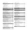
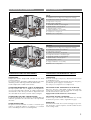
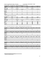
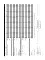
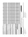
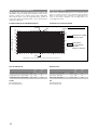
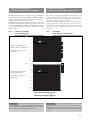
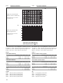
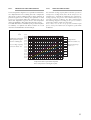
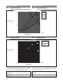
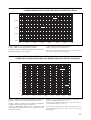
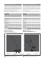
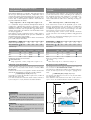
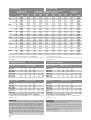
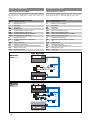
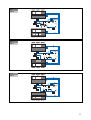
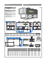
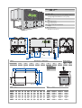
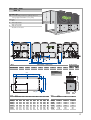
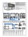
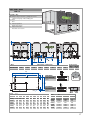
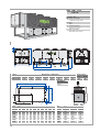
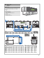
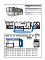
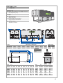
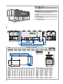
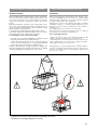

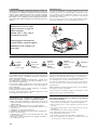

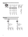
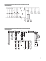
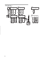
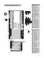
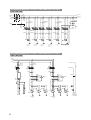

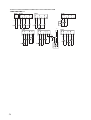
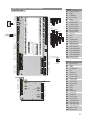
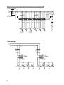
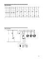
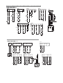
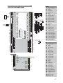
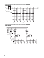
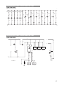
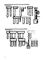
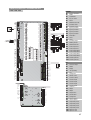
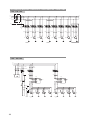
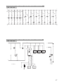


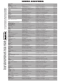


![TSD Series - User Manual [IT]](http://vs1.manualzilla.com/store/data/006100641_1-5eaa3222de544ca7b2bd1a56c36c1ff7-150x150.png)