1
Manual Book:
BOH 80 2.1 D 60
In most respects aerostatic bearings are ideally suited for use in high-speed machines. Their low
friction provides high mechanical efficiency and minimizes bearing heating problems.
They are quiet and smooth running and do not add to sound and vibration levels of the machine in
the way that high-speed ball bearing do.
Applications
One of the most important fields of application of aerostatic bearings is undoubtedly on machine tools
where the range of machine tool application is very wide.
Advantages
Almost all of the benefits result from three properties of aerostatic bearings: low friction, precise axis
definition, and the absence of wear. In comparison with spindles with ball or roller bearings, the lower
level of vibration of aerostatic bearings is an important advantage. This is particularly true in relation
to the production of good work piece geometry and surface finish, and in ensuring long life of the
cutting tool, drill or grinding wheel.
Aerostatic bearings have been employed in machines driven by most types of electric motors and
most types of turbines. They have also been employed in a wide range of machine tool spindles
driven by various types of belts and flexible couplings. In all these cases the driving torque is evenly
and smoothly applied, excepting the case of driving by means of a belt, the drive does not apply large
loads to the bearings. Aerostatic bearings are most successful when operating under these
conditions. They are much less likely to be successfully applied to machines with pulsating drives,
which impose large internal loads on the bearings.
0
CONTENTS
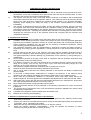
1. Fundamental Safety Instructions.
2. Warranty notice.
3. Attention – Daly Check Before starting the spindle
4. System general description.
5. Installing the spindle.
6. Specification for High – Speed Air Spindle.
7. Mechanical Constant.
8. Electrical Motor Specification.
9. Brushless DC Motor
10. Diagrams:
a) Torque & Power Vs. Rotation Speed
b) Final velocity Vs. Torque & Acceleration Time & External Inertia
c) Air Flow Vs. Air Pressure.
d) Inlet Air Flow Vs. Rotation Speed.
e) Water Flow Vs. Water Pressure.
f) Motors Temperature Vs. Rotation Speed & Cooling System
g) Motor Temperature Vs. Water Pressure
h) The Spindle Thermal Behavior
i) Shaft Extension Vs. Thermistor Resistance
j) Shaft Extension Vs. Motor Temp.
k) Radial Stiffness Vs. Air Pressure.
l) Axial Stiffness Vs. Air Pressure.
m) Radial Load Capacity Vs. Air Pressure.
n) Axial Load Capacity Vs. Air Pressure.
o) No Load Deceleration.
p) Mechanical Friction Losses.
q) Voltage Constant (BEMF).
r) Current Vs. Rotation Speed.
s) Torque Vs. Current.
t) Power Vs. Current & Rotation Speed.
u) Vibration Amplitude Vs. Rotation Speed.
v) Vibration Speed Vs. Rotation Speed.
w) Noise Level
x) Motor temperature Vs. Rotation Speed & Water Temperature
y) Torque Vs. Air Pressure
z) Load Vs. Axis Length & Air Pressure
aa) Torque Vs. Air Pressure
bb) Load Vs. Length & Air Pressure
cc) Brushes Pressure Vs. Length
dd) Brushes Wear Vs. Pressure
ee) Brushes Wear Vs. Length
ff) Brushes Lifetime Vs. Length
11. Raw Materials Data.
12. Spindle Modes.
13. Spindle Balancing.
14. Electrical System.
15. Electrical Connections.
16. Thermistor – 203GT-1.
17. Adapter for Power Cable and Signal Cable.
18. Remote Control.
19. Description of a Spindle Testing.
20. Cooling Water Sealing & Flow Test Circuit.
21. Flow Test Circuit.
22. Sensor Pressure Tuning.
27.Failure, Cause, Prevention.
28.Appendix
3
5
6
7
8
9
10
11
12
13
13
14
14
14
15
15
15
15
15
16
16
16
16
16
16
17
17
17
17
17
17
18
18
19
19
19
19
20
20
20
20
21
22
23
27
28
29
30
30
31
32
32
32
33
0
FUNDAMENTAL SAFETY INSTRUCTIONS
1. Basic operation and designated use of the machine.
1.1
The machine has been built in accordance with state of the art standards and recognized safety rules.
Nevertheless, its use may constitute a risk to life and limb of the user and of the third parties, or cause
damage to the machine and to other material property.
1.2
The machine must only be used in technically perfect conditions in accordance with its designated
use and the instructions set out in the operation manual. Only safety-conscious persons who are fully
aware of the risks involved in operation the machine should operate it. Any functional disorders,
especially those affecting the safety the safety of the machine, should therefore be rectified
immediately.
1.3
The machine is designed exclusively for drilling, grinding and milling operations. Using the machine
for purposes other than those mentioned above is considered contrary to its designated use. The
manufacturer cannot be held liable for any damage resulting from such use. The risk of such misuse
lies entirely with the user. Operating the machine within the limits of its designated use also involves
observing the instructors set out in the operation manual and complying with the inspection and
maintenance directives.
2. Organizational measures.
2.1
The operating instructions must always be at hand at the place of use of the machine.
2.2
In addition to the operating instructors, observe and instruct the user in all other generally applicable
legal and other mandatory regulations relevant to accident prevention and environmental protection.
Those compulsory regulations may also deal with the handling of hazardous substances, issuing
and/of wearing personal protective equipment.
2.3
The operations instructions must be supplemented by instructions covering the duties involved in
supervising and notifying special organizations, working sequences or the personal entrust with the
work.
2.4
Personal entrust with the work on the machine must have read the operating instructions and in
particular the chapter on safety before beginning work. Reading the instructions after work is too late.
This applies especially to persons working only occasionally on the machine e.g. during setting up or
maintenance.
2.5
Check whether personal is carrying out the work in compliance with the operation instructions and
paying attention to risks and safety factors.
2.6
For reasons of security, long hair must be tied back or otherwise secured, garment must be close
fitting and no jewelry, such as ring, may be worn. Injury must result from being caught up in the
machinery or from rings catching on moving parts.
2.7
Use protective equipment whenever required by the circumstances or by law.
2.8
Observe all safety instructions and wearing attached to the machine.
2.9
See to it that safety instructions and wearing attached to the machine are always complete and
perfectly legible.
2.10
In the event of safety-relevant modifications or changes in the behavior of the machine during
operation, stop the machine immediately and report the malfunction to the competent person.
2.11
Never make any modifications, additions or conversions, which might affect safety without the
suppliers’ approval. This also applies to the installation and adjustments of safety devices and valves.
2.12
Spare parts may comply with the technical requirements specified by the manufacturer. Spare parts
from original equipment manufacturers can be rely to do so.
2.13
Never modify the software of programmable control systems.
2.14
Adhere to prescribe intervals or those specified in the operating instructions for routine checks and
inspections.
2.15
For the execution of maintenance work, tools and workshop equipment adapted to the task on hand
are absolutely indispensable.
2.16
A portable fire extinguisher must be placed within immediate reach.
2.17
Observe all fire warning and fire-fighting.
3. Selection and qualification of personal-basic responsibilities
3.1
Any work or and with the machine be executed by reliable personnel only. Statutory minimum age
limits must be observed.
3.2
Employ only trained or instructed stuff and set out clearly the individual responsibility of the personnel
of operation, set-up, maintenance and repair.
3.3
Make sure that only authorized personnel work on or with the machine.
3.4
Define the machine operators’ responsibilities – giving the operator the authority to refuse
instructions by third parties that are contrary to safety.
3
3.5
3.6
Do not allow persons to be trained or instructed or persons taking part in a general training course to
work on or with the machine without being permanently supervised by an experienced person.
Work on the electrical system and equipment of the machine must be carried out only by a skilled
electrician or by instructed person under the supervision and guidance of a skilled electrician and in
accordance with electrical engineering rules and regulations.
4. Safety instructions governing standard operation
4.1
Avoid any operational mode that might be prejudicial to safety.
4.2
Take the necessary precautions to ensure that the machine is used only when in a safe and reliable
state.
4.3
Operate the machine only if all protective and safety oriented devices, such as removable safety
devices, emergency shut-off equipment, sound proofing elements and exhausts, are in place and
fully functional.
4.4
Check the machine at least once per working shift for obvious damaged and defects. Report any
changes (including changes in the machine’s working behavior) to the competent person
immediately. If necessary stop the machine immediately and lock it.
4.5
In the event of malfunction, stop the machine immediately and lock it. Have any defects rectified
immediately.
4.6
During start-up and shutdown procedures, always watch the indicators in accordance with the
operating instructions.
4.7
Before starting up or setting the machine in motion, make sure that nobody is in risk.
4.8
Never switch off or remove suction and ventilation devices when the machine is in operation.
5. Safety instructions governing special work in conjunction with utilization of the machine and
maintenance and repair during operation; disposal and consumable parts.
5.1
Observe the adjustment, maintenance and inspection activities and intervals set out in the operation
instructions, including information on the replacement if parts and equipment. Skilled personnel may
execute those activities only.
5.2
Brief operation personnel before beginning special operations and maintenance wok, and appoint a
person to supervise the activities.
5.3
If any work concerning the operation, conversing or adjustment of the machine and its safety oriented
devises or any work related to maintenance, inspection and repair always observe the start-up and
shutdown procedures set out in the operating and the information on maintenance work.
5.4
Ensure that the maintenance area is adequately secured.
5.5
If the machine is completely shut-down for maintenance and repair work, it must be secured against
inadvertent starting by:
- Locking the principal control elements and/or
- Attaching the “warning signal” sign to the main switch.
5.6
To avoid the risk of accidents, individual parts and large assemblies being moved for replacement
purposes should be carefully attached to lifting tackle and secured. Use only suitable and technically
perfect lifting gear and suspension systems with adequate lifting capacity. Never work or stand under
suspended loads.
5.7
For carrying out overhead assembly work, always use specially designed or otherwise safety-oriented
ladders and working platforms. Never use machine parts as a climbing aid. Wear a safety harness
when carrying out maintenance work at greater heights.
5.8
Keep all hardens, steps, handrails, platforms landing and ladders from dirt.
5.9
Clean the machine especially connections and threaded unions, of any trace of oil, fuel, or
preservative before carrying out maintenance. Never use aggressive detergents. Use lint-free
cleaning rags.
5.10
Before cleaning the machine, cove or tape all openings, which for safety and functional rezones, must
be protected against water, steam, or detergent penetration. Special care must be taken with electric
motors and switchboard cabinets.
5.11
Always tighten any screwed connections that have been loosened during maintenance work.
5.12
Any safety devices removed for set-up, maintenance or repair purpose must be ratified and checked
immediately upon completion of the maintenance work.
5.13
Ensure that all consumable and replaced parts are disposed safely and with minimum environmental
impact.
6. Warning of special dangers:
6.1
Use only original fuses with the specified current rating. Switch off the machine immediately if trouble
occurs in the electrical systems.
4
6.2
6.3
6.4
6.5
6.6
6.7
6.8
Work on the electrical system or equipment may only be carried out by a skilled electrician himself or
by specially instructed personnel under the control and supervision of such electrician and in
accordance with the applicable electrical engineering rules.
If provided for in the regulations, the power supply to parts of machine, on which inspection,
maintenance and repair work has to be carried out, must be cut off. Before starting any work, check
the de-energized parts for the presents of power and ground or short-circuit in addition to insulating
adjacent live parts and elements.
The electrical equipment of machine is to be inspected and checked at regular intervals. Defects such
as loose connectors or scorched cable must be rectified immediately.
Necessary work on live parts and elements must be carried out only in the presence of a second
whom can cut off the power supply in case of danger by actuating the emergency shut-off or main
power switch. Secure the working area with a red-and-white safety tape and a warning sign. Use
insulated tools only.
Check all lines, hose and screwed connections regularly for leaks and obvious damage. Repair
damage immediately.
Depress all system sections and pressure pipes to be removed in accordance with the specific
instructions for the unit concerned before carrying out any repair work.
Compressed air lines must be laid and fitted promptly. Ensure the no connections are interchanged.
The fittings, length and quality of the hoses must comply with the technical requirements.
7. Mobile machinery and equipment
7.1
Cut off the external power supply of the machine even if only minor changes of place are envisage.
Properly reconnect the machine to the supply mains before restarting.
7.2
For restarting process only in accordance with the operating instructions.
WARRANTY NOTICE
We warrantee this spindle to be free of material and workshop defects. This warrantee is conditional
upon proper use in the applications of which this spindle is designed to. Warrantee is void if damaged caused
due to improper use, installation, negligence, accident, inadequate maintenance to the spindle or the machine
in which it is installed. This warrant is also void if customer did not follow the complete manual and caused
damage.
In any case of damage, failure analysis will be perform by Plasel to determine the cause of the failure.
Warrant is void if damaged caused by inadequate machine maintenance or improper use ex. Leaky valves, Zaxis leakage wear, contained air supply, lower/higher air presser, inadequate vacuum, using the spindle to
work on material that is too hard, drilling into anything other then the right material.
5
ATTENTION
DAILY CHECK BEFORE OPERATING THE SPINDLE
1. For first time installation, look at “Installing the spindle”
paragraph.
2. Check air supply (5-6 bar.)
3. Check water supply (4-5 bar.) Check water supply (4-5 bar.)
4. Check ventilation exits.
5. Check for free movement of the shaft.
6. The spindle must be securely clamped to the machine and clear
from any distraction.
7. Check for electric connections and command (community
grounding).
8. Start the spindle.
6
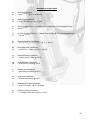
General Description
7
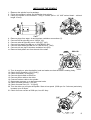
INSTALLING THE SPINDLE
1. Remove the spindle from its package.
2. Follow the machine’s safety and installation instructions.
3. Clamp the spindle to the machine - using 5 screws (M6 or 1\4” UNF socked head – minimal
length 15 mm).
4.
5.
6.
7.
8.
9.
Remove plugs from water, air and brushes ventilation connections (5).
Connect inlet air pipe Ø6 mm to “AIR IN” (AI).
Connect outlet air pipe Ø5 mm to “AIR OUT” (AO).
Connect inlet water pipe Ø8 mm to “WATER IN” (WI).
Connect outlet water pipe Ø8 mm to “WATER OUT” (WO).
Connect Ø 4 mm pipe to brushes ventilation hole (BV).
10. Remove black plastic nut from the end of the shaft.
11. Turn air supply on, spin the shaft by hand and make sure that the shaft is rotating freely.
12. Check for air pressure ( 4.5-5.5 [bar].)
13. Check for airflow ( 35-55 [lpm].)
14. Connect signal cable to the driver.
15. Connect power cable to the driver
16. Connect brushes cable to the spindle.
17. Open water pressure on to derivate water leaks.
18. Check for water pressure (4-5 bar)
19. Check for water flow (2.5 – 3.5 [lpm])
20. Turn the driver on and spin the spindle. Start at low speed (5000 rpm for 5 minutes) and slowly
increase up to 60 Krpm.
21. Check for motor current at 5000 rpm, less 0.5 Amp.
8
SPECIFICATION FOR HIGH-SPEED AIR SPINDLE
Rotation speed – 2K ~ 75K [rpm]
Air supply
Pressure
Flow rate
Filtering
Dew point
Oil residue
:5~7
:45-55
:0.01
:lower then 15
:lower then 0.1
[bar]
[lpm]
[µm]
[ C]
[ppm]
:5
:1-3.5
:20 ~ 25
:within 1
[bar] (72.5 psi)
[lpm]
[oC]
[oC]
:0.35
:0.35
[µm]
[µm]
:1
:1
:0.3
:0.3
[µm]
[µm]
[µm]
[µm]
:14
:9
[N/µm]
[N/µm]
:60
:100
[N]
[N]
PCW (Pure Clean Water – pure H2O)
Coolant Water
Pressure (max)
Flow rate (min)
Temperature
Variation range
Static run-out of the rotor
Radial direct.(max)
Thrust direct (max)
Dynamic run-out of the rotor
Radial direct(max)
Thrust direct.(max)
Radial direct. Fluctuation between peaks
Thrust direct. Fluctuation between peaks
Rigidity of the rotor
Radial direct.
Thrust direct.
Load capacity
Radial direct.
Thrust direct.
General
Shaft Axial Extension @ Tm = 40 [oC]
Spindle Weight
Rotor Inertia
Noise level 0 up to 10 Krpm (max)
Resistance between shaft & frame
Balance:G0.4 @ ISO 1940
CE standard
Floating Point
Cables` length: Power cable
Signal cable
Brushes cable
Brushes life-time@ 30-40 Krpm
:4
[µm]
:6.7
[Kg]
:6.5E-5
[Kg*m2]
:70
[db a]
:1
[MΩ]
:0.03
[gmm]
: corresponding
:2
[bar]
:1.25
[m]
: 1.3
[m]
: 1.15
[m]
: 2500
[hr]
Mechanical Coefficient
Air Flow Coefficient
Water Flow Coefficient
Still Air Cooling Efficiently
Air Flow Cooling Efficiently
Shaft Extension Coefficient
Mechanical Friction Coefficient
Stiffness & Load Coefficient
Thermal Behavior Coefficient
Radial Stiffness Coefficient
Axial Stiffness Coefficient
Radial Load Coefficient
Axial Load Coefficient
:Af = 38.14
:Wf = 2.84
:Cs = 28.8
:Ca = 54
:ES = 0.055
:FL = 0.043
:SL = 0.417
:Bt = 3.6-4
:Sr = 16.487
:Sa = 10.06
:Lr = 71.54
:La = 91.84
9
MECHANICAL COEFFICIENT
Af
Af
Air Flow Coefficient
= 43*e-0.002*Vsp @ Vsp = 60 [Krpm]
Wf
Wf
Water Flow Coefficient
= 0.9+1.4*In {Pw} @ Pw = 4 [bar]
Cs
Cs
Still Air Cooling Efficiency:(Water Flow Cooling/Still Air Cooling)@60 Krpm
=80*e-0.017*Vsp
Ca
Ca
Air Flow Cooling Efficiency: (Water Flow Cooling/Air Flow Cooling)@60Krpm
= 82.3*e-0.007*Vsp
Bt
Bt
Thermal Behavior Coefficient
= [(Tr-Tf)2 + (Ts-Tf)2 + (Ts-Tr)2 ]-1/2 @ Tm = 100 [Cº]
Es
Es
Shaft Extension Coefficient
= (0.236*Tm – 5.426)-1 @ Tm = 100 [cº]
Sr
Sr
Radial Stiffness Coefficient
= 13.642*In(Ps)-7.956 @ Ps=6
Sa
Sa
Axial Stiffness Coefficient
= 6.425*In(Ps)-1.454 @ Ps=6
Lr
Lr
Radial Load Coefficient
= 64.39*In(Ps)-43.832 @ Ps=6
La
La
Axial Load Coefficient
= 67.664*In(Ps)-29.4 @ Ps=6
Fl
Fl
Mechanical Friction Coefficient
= (6.5*10-3*Vsp2)-1 @ V = 60 Krpm
Sl
Sl
Stiffness & Load Coefficient
= 7*10-4[4(Sr+Sa)+3(Lr+La)] Sl = 0.417
10
ELECTRICAL MOTOR SPECIFICATION
•
•
•
•
•
•
•
•
•
•
•
•
•
•
•
•
•
•
•
•
•
•
•
•
Size Constants:
Maximum Rated Torque
Maximum Continuous Stall Torque
@ Temp. Rise 100 [ºC]
Motor Constant
Electrical Time Constant
Mechanical Time Constant
Angular Acceleration (theoretical)
Thermal Resistance
Maximum Cogging Torque
Viscous Damping
Hysteresis Drag Torque
Rotor Inertia Frameless
No. of Poles
Winding Constants:
Design Voltage
Peak Torque
Torque Sensitivity
Peak Current
No Load Speed
Voltage Constant
Terminal Resistance
Terminal Inductance
: Tr = 2.13
[Nm]
:
:
:
:
:
:
:
:
:
:
:
Tc = 0.30
Km = 0.03
Te = 0.46
Tm = 3
800000
TPR =0 .65
Tf = 9.180E-03
Fi = 1.038E-07
Th = 2.481E-04
Jm = 2.596E-06
P=6
[Nm]
[Nm/√w]
[msec]
[msec]
[rad/sec²]
[ºC/watt]
[Nm]
[Nm/rpm]
[Nm]
[Kg*m²]
:
:
:
:
:
:
:
:
Vp = 150
Tp = 2.13
Kt = 0.02
Ip = 120
Snl = 8500
Kb = 0.02
Rm = 0.36
Lm = 0.17
[Volt]
[Nm]
[Nm/Amp]
[Amp]
[rad/sec]
[v/rad/sec]
[Ohm]
[mH]
RMS Torque Performance
•
•
•
(Performance @ 25 Cº):
D esign Voltage
Continuous Power Output
•
•
•
•
•
•
•
•
•
•
•
•
•
•
•
•
Torque
Speed
Iphases
I (dc-link)
Efficiency
Temperature Rise
Ambient temperature
Cooling
: Vp = 150
: Power = 1200
: 1.6
: 0.2
: 60000
: 12.4
: 8.75
: 92
: 70
: 25
: Water cooling
[Volt]
[watt]
[Hp]
[Nm]
[rpm]
[Amp]
[Amp]
[%]
[ºC]
[ºC]
Mechanical:
Lamination Material
No. of phases
Phase Connection
Parallel path
Turns/Coil
Wire Gage (AWG)
Lead wire Gage (AWG)
:
:
:
:
:
:
:
C49
3
DELTA
1
21
27
24
11
Brushless DC Motor
Maximum Continuous Stall Torque (TC) is the amount of torque produce at zero speed, which results in a 100 Cº
rise in temperature. Generally the highest operation temperature that should be allowed is 150 Cº and is a
combination of the ambient temperature and the temperature rise for a given operating condition.
Maximum rated Torque (TR) is the amount of torque that the motor can produce without demagnetizing the rotor.
The torque is only available for short durations. Also, it may not be possible to produce the Maximum rater torque
because of limitations of voltage and current (see peak torque).
Motor Constant (KM) is the rations of the peak torque to the square root of the input power at stall which 25 Cº
ambient temperature. The ratio is useful during the initial selection of a motor since it indicated the ability of the
motor to convert electrical power into torque.
KM = TP (Peak Torque / √PP (Peal Input Power)
Or
KM = KT (Torque Constant / √RM (Terminal Resistance)
Electrical Time Constant ( tF) is the ration of inductance (LM) IN henries, to the resistance RM IN ohms. This is
the inductance and resistance as measured across any two phases in a delta or wye configuration.
TE = LM / RM
Mechanical Time Constant (tM) is the time required to reach 62.3% of the motor maximum speed after the
application of constant DC voltage trough the commutation, ignoring friction, wind age and cross losses.
TM = JM * RM / KT*KB
Thermal Resistance (TPR) correlated winding temperature rise to the average power dissipated in the stator
winding. The published TPR assumes that a housed motor is mounted to an aluminum heat sink of specific
damnations. Additional cooling from forced air, water jacketing, or increased heat sinking decreases the motor
Thermal Resistance allowing higher power output then the published date.
Viscous damping (F0) gives an indication of the torque lost due to B.E.M.F in the motor when the source
impedance is zero. F0 value can be represented as F0 = KT Maximum Cogging Torque (TF) is principally the static
friction torque felt as the motor is rotated as low speed. The published value does not include the bearing friction of
a housed motor.
Number of Poles ( NP) is the number of permanent magnet poles of the rotor. For the QB Series this is generally a
total of six (three north and three south)
Design Voltage (VP) is the nominal voltage required to produce the peak torque when the rotor speed is zero and
the winding temperature is 25 ºC. as such VP is the product of IP and RM. at any temperature greater then 25 ºC, the
required voltage to produce peak torque increases due to the increase in winding resistance. The design voltage is
not a limit but a reference point for the date.
Peak Torque (tP) is the nominal value of developed torque with the rated current IP applied to the windings. For
each winding specified the product of peak current (IP) and nominal torque sensitivity (kT) gives TP unless the
maximum rated torque (TR) is reached.
Peak Current (IP) is the rated current used to obtain the nominal peak torque from the motor with nominal torque
sensitivity (KT). IP is generally the design voltage divided by the terminal resistance (RM).
Torque Sensitivity (kT) is the ratio of the developed torque to the applied current for a specific winding. KT is
related to the BEMF constant KB.
No load Speed (SLN) is the theoretical no load speed of the motor with the design voltage applied.
BEMF Constant (kB) is the ration of voltage generated in the winding to the speed of the rotor. KB is proportional to
KT.
Terminal Resistance (RM) is the winding resistance measured between any two leads of the winding in either a
delta or wye configuration at 25 ºC.
Terminal Inductance (LM) is the winding inductance measured between any two leads of the winding in either a
delta or wye configuration at 25ºC.
12
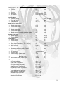
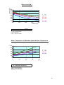
Torque & Power Vs. Rotation Speed
PW [W]]
T [Nm]
1600
0.3
0.25
1200
Nominal Power
0.2
0.15
800
0.1
400
0.05
0
0
0
20
40
60
0
80
Vsp [Krpm]
Vsp [Krpm] - Rotation Speed
T [Nm ]
- Spindle Torque
Pw [w ]
- Nominal power
20
40
60
80
Vsp [krpm]
Conditions
1. Temp Rise less then 100° C.
2. Continuous operation at a load point.
3. The curves assume a 25°C ambient environment.
4. No external loads.
Continuous Duty Speed/Torque Curves for 100°C Temperature Rise.
The continuous duty speed/torque curves provide a guide to the operational capability of the motors. Continuous operation at a load
point on or under the curve limits the temperature rise of the motor to 100oC. Although the duration of acceleration or deceleration periods
should be checked, the RMS speed and torque combination should also lie on or under the continuous duty curve .The curves assume a 25oC
ambient environment. Higher ambient temperatures will generally decrease the continuous duty capability of a motor. The continuous duty
capability of the motor may be increased. However, for most application, the practical maximum motor temperature is 150oC with Hall effect
sensors. Higher motor temperatures can easily be accommodated with different materials.
EMOTEQ U.K. Ltd
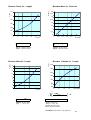
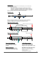
Final Velocity Vs. Torque , Acceleration Time & External Inertia.
V [Krpm] J 1 = 5 * 10
100
-4
kg*m 2
J 2 = 5 * 10 - 5 kg*m 2
100
80
T1
0
2.21
T2
0
15.59
T3
0
24.52
0
3
6
V [Krpm]
100 [Krpm]
Vsp
80
60
0
80
9
12
15
18
J 3 = 5 * 10 - 6 kg*m 2
T1
T2
0
0
0.26
1.86
21
24 27
t [sec]
T3
0
2.92
60
T3
0
5.01
20
0
0
100
20
0
0
1
1.5
2
2.5
3
J 4 = 5 * 10 - 7 kg*m 2
T1
T2
0
0
0.245
1.73
60
20
0.5
V [Krpm]
80
40
0.3 0.6 0.9 1.2 1.5 1.8 2.1 2.4 t 2.7
[sec] 3
T2
0
3.19
40
40
0
T1
0
0.452
80
60
Vsp
[Krpm]
40 0
20 80
0
VVsp
[Krpm]
[Krpm]
0
3.5
4
4.5 5
t [sec]
T3
0
2.73
0.3 0.6 0.9 1.2 1.5 1.8 2.1 2.4 2.7 3
t [sec]
t [sec]
- Decelerations time.
T1=2.13 [N*m] - Peak Torque.
V [Krpm]
- Speed.
T2=0.302 [N*m] - Continuous Stall Torque.
T [Nm]
- Torque.
T3=0.192 [N*m] - RMS Torque.
J [kg*m 2 ] - External Inertia.
13
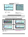
Air Flow Vs. Air Pressure
Fai[LPM]-1
15.882
21.864
26.359
30.098
33.36
36.286
38.959
41.433
43.746
45.924
Air [LPM]
Pai [bar]
50
0.5
1
40
1.5
2
2.530
3
3.520
4
4.510
5
Fao[LPM]-2
6.35
7.012
7.743
8.55
9.442
10.436
11.513
12.714
14.039
15.503
Fbv[LPM]-3
9.554
10.775
12.153
13.707
15.459
17.436
19.665
22.179
25.015
28.213
Fsh[LPM]-4
9.6
14.067
18.533
23
27.467
31.933
36.4
40.867
45.333
49.8
0
0
0.5
1
1.5
2
2.5
3
3.5
4
4.5
5
Pai [bar]
CONDITION
1. Ambient Temperature - 22 [0C]¸24 [0C]
2. No Rotation.
3. Inlet pipe diameter D=4 mm.
4. Inlet pipe length L=1500 mm.
5. No tool holder.
6. Including brushes.
7. Air outlet ventilated.
8. Flowting Point - 2 bar.
Vsp [Krpm]
43
5
40
37
40.356
Fai[LPM]
10
42
15
41
20
40
25
39
30
38
35
45
5
50
55
60
Flh [LPH]
65
Pw[bar]
1
120
1.5
260
2.5
0
3
3.5
Flm [LPM]
4
4.5
5
0
4
39.722
FBV=8.471*e
0.241*PAI
Pai [bar] - Inlet Air Pressure.
Fbv [LPM] - Air Flow in Sensor Ventilation.
Outlet Air Flow
FAO=5.75*e
0.198*PAI
Pai [bar] - Inlet Air Pressure.
Fao [LPM] - Air Flow in spindle exit.
CONDITION
1. Pipe diameter at checking point D=4 mm.
2. Pipe length at checking point L=1000 mm.
35
45
55
65
75
Vsp[Krpm]
39.409
39.098
1.5
CONDITION
1. Ambient Temperature - 22 [0C]¸24 [0C]
2. Ambient Humidity 60%.
3. Including sensor brushes.
4. Entry pressure Pai = 5 [bar].
Water Flow Vs. Water Pressure
38.484
38.18
37.879
170.96
180.735
189.479
3
Sensor Ventilation Air Flow.
Vsp [Krpm] - Rotation Speed
Fai [LPM] - Inlet Air Flow
40.038 25
15
Flh[LPH]
55.911
89.561
113.436
131.954
147.085
0.5159.878
1
Pai [bar] -Inlet Air Pressure.
Fai [LPM] - Inlet Air Flow.
FAI = 43*e(-0.0013VSP)
38.789
70
240
75
180 80
FAI=21.864*PAI0.461
Inlet Air Flow Vs. Rotation Speed.
Fai[LPM]
42.656
42.319
41.986
41.655
41.326
41
40.677
Inlet Air Flow.
Flow=α+β*ln(Pressure)
Flm[LPH]
0.932
1.493
1.891
2.199
2.451
2 2.5
2.665
Flow @ LPH α=56, β=83
Flh=56+83*ln(Pw)
3
3.5
4
4.5 5
Pw [bar]
Flow @ LPM α=0.9, β=1.4
Flm=0.9+1.4*ln(Pw)
Pw[bar] - Water Pressure
Flh[LPH] - Water Flow in L/H
Flm[LPM] - Water Flow in L/M
2.849
3.012
3.158
CONDITION
1. Water Temperature - 18 [0C]¸20 [0C]
2. Room Temperature - 22 [0C]¸24 [0C]
2
3. No Rotation.
1
0
0
0.5
1
1.5
2
2.5
3
3.5
4
4.5 5
Pw [bar]
14
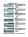
Motors Temperature Vs. Rotation Speed & Cooling System
Temp[C]
150
Temp = a*e
b*Vsp
0.02*VSP
TW = 18*e
TA = 19*e0.04*VSP
TSA = 20*e0.055*VSP
100
50
0
0
10
20
30
40
50
60
Temp [° C] - Motor temperature
70
80
V SP [Krpm]
Vsp [Krpm] - Speed rotation
CONDITION
2. Still air cooling.
1. General.
60
40
20
Motor Temperature Vs. Water Pressure
5
15.623
14.641
14.198
10
17.592
16.526
16.046
15
19.741
18.575
18.052
20
22.106
20.82
20.245
25
24.737
23.303
22.665
30
27.701
26.08
25.363
35
31.094
29.231
28.413
40
35.061
32.871
31.918
545 15 39.839
25
3537.181
45
55 36.04
65
75
50
45.843
42.464
41.045
VSP[Krpm]
55
53.934
49.293
47.413
60
66.379
58.965
56.181
P1=1bar
P2=3 bar
Tm [° C]
80
70
60
50
40
30
20
10
0
10
20
30
40
50
60
70
80
90
o
Tm [ C]
0.019*Tm
Ts = 15.92*e
0.018*Tm
Tf =15.487*e
0.013*Tm
Tr =17.58*e
P3=5bar
T=22*PW(-0.06)*e0.02*VSP
Vsp [Krpm]
Pw[bar]
The Spindle Thermal Behavior
o
80
Water Temperature 12 [°C].
Water Pressure 5 bar.
Cooling Water Flow 3.2 LPM.
Air Flow 40 LPM.
Air Pressure 5 bar.
Tf,Ts,Tr [ C]
Temp[C]
100
4. Water flow cooling.
3. Air flow cooling.
No tool holder (wheel mount).
Including sensor.
Ambient Temperature 22-24 [°C].
Temp. Measurement - termistor.
Tm [° C]
Tf [° C]
Ts [° C]
Tr [° C]
- Speed rotation
- Water Pressure
- Motor temperature.
- Motor temperature.
- Temperature in the front area.
- Temperature in the middle area.
- Temperature in the rear area.
CONDITION
CONDITION
1. Driver - BDH - Hathaway.
2. Ambient Temperature 22-24 [°C].
3. Ambient Humidity 60%.
4. Temp. Measurement termistor - SEMITEC 203GT-1.
Ω
1. No cooling.
2. Ambient Temperature 22-24 [°C].
3. Ambient Humidity 60%.
4. Air Pressure in entrance 5 bar.
∆L[10 3mm]
Shaft Extension Vs. Thermistor Resistance
∆L [µ]
9
6
3
0
0
2
4
1.688
2.244
2.982
3.964
5.268
7.002
9.307
12.37
6
8
CONDITION
Shaft Extension Vs. Motor Temp
20
25
30
35
40
45
50
55
8
6
∆ L [µ]
16
14
12
10
8
6
4
2
12
4
2
0
10
12
14
16
R [ Ω]
0
20
30
40
50
60
Tm [ o C]
∆L = 0.236*Tm-5.426
-0.142*Rmotor
∆L= 16.442*℮
1. Ambient Temperature 22-24 [°C].
2. End shaft extension.
3. Reaction time for temperature stabilization
in shaft ~ 5 min.
10
-0.694
0.489
1.672
2.855
4.038
5.221
6.404
7.587
∆L[ µ ]
R[ Ω ]
Tm [° C]
- Shaft extension
- Termistor resistance
- Motor temperature
15
Ps[bar]
20
Sr[N/m]
Radial Stiffness Vs. Air Pressure
Sa [N/ µ ]
Sr [N/ µ ]
2
1.5
Sr=13.642*ln(Ps)-7.956
2.5
4.544
3
7.031
Theoretical curves
3.5
9.134
Ps [bar] - Spindle air pressure.
4
10.956
Sr [N/ µ ] - Radial Stiffness.
4.5
12.563
5
14
CONDITION
05.5 1
215.3 3
4
5
6
7
8
1. No Rotation.
Ps [bar]
6
16.487
2. Distance Form The End of The Spindle - 18mm
6.5
17.579 Axial Stiffness Vs. Air Pressure
7
18.59
15
Ps[bar]
Sa[N/m]
Sa=6.425*ln(Ps)-1.454
2
3
10
2.5
4.434
Theoretical curves
3
5.605
5
Ps [bar] - Spindle air pressure.
3.5
6.596
Sa [N/ µ ] - Axial Stiffness.
4
7.454
0
4.5
8.211
CONDITION
0 5 1
2
3
4
5
6
7
8
8.888
1. No Rotation.
Ps [bar]
5.5
9.5
6
10.059 Radial Load Capacity Vs. Air Pressure
6.5
10.573
90
7
11.05
16
12
8
4
0
Lr=64.39*ln(Ps)-43.832
Theoretical curves
75
La [N]
Lr [N]
Ps[bar]
60
45
30
15
0
125
100
75
50
25
0
2
2.5
3
3.5
4
4.5
0
5
5.5
6
6.5
Lr[N]
1
0.8
Ps [bar] - Spindle air pressure.
15.168
Lr [N]
- Radial load capacity.
26.908
36.834
2. Distance Form The End of The Spindle - 18mm
45.432
CONDITION
53.016
1. No Rotation.
2
3
4
5
6
7
59.8
Ps [bar]
65.937
71.54 Axial Load Capacity Vs. Air Pressure
76.694
La=67.664*ln(Ps)-9.4
Theoretical curves
Ps [bar] - Spindle air pressure.
La [N]
- Axial load capacity.
2
3
4
5
6
7
Ps [bar]
Vsp [Krpm]
No Load Deceleration
Fl [w]
t
70
60
50
[sec]
40
0
30
2
20
4
10
60
8
10 0
12
14
16
35
18
30
20
22
25
26
20
28
15
30
10
Vsp[Krpm]
Vsp =62.7*e
62.7
51.78
42.76
35.31
29.16
4 24.08
8
19.88
16.42
13.56
11.2
9.25
7.64
5.21
4.3
3.55
10
12
16
20
24
28
32
t [sec]
Mechanical Friction Losses
FL [w]
- Friction Loss.
Vsp [Krpm] - Spinning Speed.
0
0.161
20
0.647
CONDITION
1. Ambient temperature 22°C.
2. Water cooling.
3. No external mechanical load.
4. Air pressure at entrance - 5 bar.
FL = 6.5*10-3*VSP2
Fl[w]
10
- 0.096*t
t [sec]
- Deceleration time.
Vsp [Krpm] - Speed in "t" time
Vsp[Krpm]
50
05
0
CONDITION
1. No Rotation.
30
40
50
60
70
Vsp [Krpm]
CONDITION
1. No external mechanical load.
2. Ambient temperature 22°C.
3. Air pressure - 5 bar.
16
Vsp[Krpm]
Vf[Volt]
5
9.27
150
10
15
90
20
60
25
30
30
35
0
40
45 0
50
55
60
3
Vf [Volt]
120
2.5
65
If [Amp]
702
18.54
27.81
37.08
46.35
55.62
64.89
74.16
1083.43 20
92.7
101.97
111.24
Vf = 1.854*Vsp
Vsp [Krpm] - Rotation Speed
Vf [Volt]
- Voltage between two phases.
30
40
50
60
70
Vsp [Krpm]
Current Vs. Rotation Speed
120.51
If = 0.159*e
129.78
5
1.5
10
1
15
0.5
20
0
T [Nm]
Voltage Constant ( BEMF)
25 0
30
35
40
45
1.5
50
0.194
0.237
0.289
0.353
100.432 20
0.528
0.645
0.788
0.962
1.176
1
55
60
1.437
1.755
65
70
0.5
0
0
30
40
50
60
70
Vsp [Krpm]
If [Amp]
- Current Phases.
Vsp [Krpm] - Rotation Speed.
CONDITION
1. Driver - BDH - Hathaway.
2. No external load.
3. Including Sensor Brushes.
4. No tool holder.
5. Humidity - 50%.
6. Ambient temperature 22-24 [o C].
Torque Vs. Current
T = 0.018*I
2.145
Kt = 0.018 Nm/Amp
2.62
2
0.04*Vsp
4
6
8
10I [Amp] 12
T [Nm]
- Spindle Torque.
I [Amp]
- Current.
Kt [Nm/Amp] - Torque Sensitivity.
Power Vs. Current & Rotation Speed
1500
P = 18*I*Vsp
Pw [W]
1200
I [Amp]
- Current.
Vsp [Krpm] - Rotation Speed
Pw [W]
- Power.
900
600
V=1Krpm
V=4Krpm
300
5
0
1 10
0.25
Vaf [ µ m]
0.2
0.1
0.05
0
Vsf [mm/s]
1.2
0.8
0.4
0
V=3Krpm
V=6Krpm
Vsp[Krpm]Vf[Volt]
0
0.15
V=2Krpm
V=5Krpm
5
10
15
20
25
0 30 5
35
40
45
50
55
60
5
10
15
20
25
30
0
5
35
55.095
3
4
59.165
63.535
2
15
20
25
0
1200
40
0.061
0.1
10
10
6
7
I [Amp]
Vibration Amplitude Vs. Rotation Speed
73.267
90.731
0.123
0.139
0.151
15 20
0.161
0.17
0.177
0.184
0.19
0.195
0.2
0.061
0.396
0.653
0.842
0.952
1
15
5
20
0.943
25
30
0
6
Vaf=0.056*ln(Vsp)-0.03
Vaf [ µ m]
- Vibration Amplitude.
Vsp [Krpm] - Rotation Speed.
35
40
45
50
55
60
CONDITION
1. Peek to Peek.
Vsp [Krpm]
Vibration Speed Vs. Rotation Speed
-5
2
-3
-3
Vsf=-7.5*10 *Vsp +4.5*10 *Vsp-17.5*10
Vsp < 30 Krpm
Vsf=0.15-0.029*ln(Vsp)
Vsp > 30 Krpm
Vsf [mm/s] - Vibration Speed.
Vsp [Krpm] - Rotation Speed.
25
30
35
40
45
50
55
60
Vsp [Krpm]
17
Noise [db]
Noise Level [db ]
69
68
67
66
65
64
63
200
250
300
350
400
VSP
VSP
VSP
VSP
VSP
VSP
=60
= 50
= 40
= 30
= 20
= 10
Distance [cm]
(0.003*D)
LP = 100.3-6.7*ln(D)+0.44*e
*ln(VSP)
VSP [Krpm] - Rotation Speed
N [ dB] - Noise Level
D [cm] - Length from Spindle
TM
Motor Temperature Vs Rotation Speed & Water Temperature
120
100
80
VSP
VSP
VSP
VSP
60
40
= 80
= 60
= 40
= 20
20
0
0
20
40
60
80
TW
T M = 0.457*(28.1+0.82*T W)*e0.013*vsp
[C] TM = Motor Temperature
[C] TW = Water Temperature
[Krpm] VSP = Rotation speed
18
MA[Nm]
Moment Vs. Air Pressure
MA =1.4*PS -3
9
8
7
6
5
4
3
2
1
0
0
2
4
6
8 PS [bar] 10
[Nm] M A = Axial Moment
[bar] PS = Spindle Air Presuure
LA [N]
Load Vs. Axis Length & Air Press'
150
100
50
PS = 7
0
50
70
90
110
PS = 6
130
a[mm]
PS = 5
LA =103[1.4*PS-3]*a-1
[N] LA = Axial Load
[bar] PS = Spindle Air Press'
[mm] a= Length From the Axies
Load Vs. Length & Air Pressure
100
1.6
Lr [N]
M [Nm]
Moment Vs. Air Pressure
1.4
75
1.2
1
50
0.8
0.6
25
0.4
0.2
0
0
2
4
6
PS [bar]
8
15
45
75
PS =5
105
PS =6
PS =7
-1
Mr =ln(PS)- 0.7
Lr =100[10*ln(PS)- 7]*a
[Nm] M r = Radial Moment
[bar] PS = Spindle Air Press'
[N] Lr = Radial Load
[bar] PS = Spindle Air Press'
[mm] a = Length Form Spindle's End.
135
a[mm]
19
Brushes Press' Vs. Length
Brushes Wear Vs. Pressure
W b [Mn]
PC[bar]
1.2
1
20
17.5
15
0.8
12.5
0.6
10
7.5
0.4
5
0.2
2.5
0
0
0
5
10
15
20
0
25
30
LC[mm]
0.4
0.6
PC = 0.2*e0.06*LC
WB = 17.24*PC-1.5
[bar] PC = Brushes Pressure
[mm] LC = Brushes Length
[Mm] Wb = Brushes Wear
[bar] PC = Brushes Pressure
0.8
1
1.2
PC [bar]
Brushes Lifetime Vs. Length
LT [hr]
Brushes Wear Vs. Length
W b [Mm]
0.2
19
17
2800
2400
15
2000
13
1600
11
9
1200
7
800
5
400
3
6
11
16
21
26
10
31
X [mm]
14
18
22
26 b [mm]30
b
a
0.06x
WB = 3.45*e
-1.5
[Mm] Wb = Brushes Wear
[mm] X = Brushes Length
1000
0.06x
-1.5
3.45*e
dx
Lt = 2045.45*ln(b)-4230.57
[mm]b = Final Length
[mm] a = Primery Length
[mm] X = Brushes Length
[hr] Lt = Brushes Life-Time
Condition :Initial Pressure = 0.9bar @ 28mm
20
Raw Materials Data
The Spindle is made from the following materials:
Stainless steel:
SAE 303,
SAE 2316.
Brass SAE 40, Copper.
Polymers:
Delerin
SAE 303
%C
0.15
%Si
1
%MN
2
%P
0.2
%S
0.15-0.4
%CR
17-19
%MO
0.6
%Ni
8--10
SAE 2316
%C
0.34
%Si
0.16
%MN
0.88
%P
0.025
%S
0.003
%CR
15.12
%MO
0.91
%Ni
0.53
Hardness HB
0.2% proof stress N/mm2
0.1% proof stress N/mm2
Tensile strength N/mm2
Elongation (L=5d) % min
Core strength N/mm2
Modulus of elasticity 103 N/mm2
Density kg/dm3
Thermal conductivity W/(m.K)
Electric resistivity Ohm.mm2/m
Specific heat capacity J/(kg.K)
Tensile strength N/mm2
Elongation (L=5d) % min
Hardness HB
Chemical composition
BRASS SAE 40
COPPER Cu
%Cu
58.1
%Cu
99.96
%Pb
2.83
%Pb
0-8
%Al
0.01
%Bi
0-1
%Fe
0.29
%Ni
0.1
%Sn
0.24
Mechanical properties
SAE 303
SAE 2316
262
235
190
225
500-750
35
900-1100
223
7.9
7.7
15
15
0.73
0.8
500
430
Mechanical properties
BRASS SAE 40
COPPER Cu
310
257
30
24
80
83
Corresponding standard
SAE 303
SAE 2316
Din 1.4305
Din 1.2316
X8CrNiS18-9
X36CrMo17
Z10CNF1809
Z35CD17
S30300
THYROPLAST 2316
Typical properties
Silver graphite
Item
SX-70
Buik density g/cm3
4.45
Hardness
15
Specific resistivity m W*m
0.25
Flexural atrength Mpa
40
Paripheral speed (MAX), m/sec
20
Current density (MAX), A/cm2
15
Delerin
Density
1.43
Tensile strength, kg/cm2
660
Pressure strength, kg/cm2
600
Flexural strength, kg/cm2
1000
Modle hardness, kg/cm2
27000
Elongation, %
25
Hardness
R120
Abrasion mg less for 1000 revolu
20
21
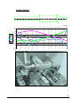
SPINDLE MODES
0
10
20
30
40
50
60
70
80
Length[mm]
90 100 110 120 130 140 150 160 170 180 190 200 210 220
1.25
1
0.75
1
2
3
4
0.5
0.25
0
5 -0.25
6
-0.5
-0.75
-1
-1.25
22
SPINDLE BALANCING
Why is balancing important?
Force (F) generated by unbalance can be calculated from formula:
F(Kg)= 0 . 001 x(gmm)x(RPM/ 1000 ) 2
2
F(Kg)= 0 . 001 x(w x r)x(RPM/ 1000 )
r
where w = Unbalance weight in grams
r = Radius in millimetres
Effects of Unbalance
Reduced component life.
Bearings, seals, windings, rotor bars, foundations, supports.
Impaired clearancs / tolerances.
Component displacement, Reactive misalighment.
Resonance.
Flexing of critical speed rotors.
Excessive vibration and noise
Health / safety considerations
Poor product quality.
Diagnosing Unbalance
Vibration frequency equals rotor speed.
Vibration predominantly RADIAL in direction.
Stable vibration phase measurement.
Vibration phase shifts in direct proportion to measurement
direction.
Causes of unbalance
Rotor not mass centred geometrically
Machining / casting inaccuracioes.
Fitting / assembly tolerance inaccuracies.
Uneven mass distribution
Windings / commutator segments.
Blow holes / inclusions in castings.
Component mismatch.
Keys / keyways.
Causes of unbalance
Service effects
Thermal dimensional changes:
Stress relieving.
Uneven thermal growth.
Thermal displacement / loosening of components.
Displacement / settling of components:
Windings Impellers Fan side plates.
Deposit build-up / Erosion / corrosion.
Rotor flexibility
Forced whip.
critical speed deflection.
Induced by other forces
Aerodynamic.
Hydraulic.
Electrical.
23
Rigid Rotors
Maximum operating speed below 70% of natural frequency or first critical speed.
Can be balanced at any speed:
Will remain in balance throughout speed range provided
tolerance, calculated to maximum service speed, is achieved.
tolerance, calculated to maximum service speed, is achieved.
Balance corrections made in any two arbitrary correction planes.
Flexible rotor
Does not satisfy the definition of a rigid rotor and has a tendency
to bend or distort due to centrifugal and unbalance forces
High speed flexible shaft
balance correction (low speed)
balance correction (low speed)
rotating centerline
mass centreline
C of G
initial unbalance
High speed flexible shaft
effect at high speed
C of G
Correcting Unbalance
In-Situ Requirements
In-situ balancing is best.
In-situ balancing is not always
possible.
Unbalance is primary problem.
Access to add / remove weight.
Ability to start / stop machine "at will"
Balance Tolerances
ISO 1940/1 has also been adopted by:
Manufacturers' recommendation.
International standards ISO 1940/1.
BS 6861 Part 1 (British Standards)
ANSI S 2.19-1975 (American National
Standards Institute)
VDI 2060 (German Standards)
24
ISO Rotor Classifications
GO.4
Spindles, precision grinders, Gyroscopes.
G1
Small special purpose electrical rotors / drives.
G2.5
Gas / steam turbines, Turbo compressors, machine tool drives. Small
and special purpose electric rotors.
G6.3
Fans, Pump impellers, general electric rotos, centrifuge drums,
general machinery parts.
Balance Tolerances
ISO 1940 / 1
MCD (e µ m) = G x 1000 = 9549 x G
2 π n/ 60
n
Where:
G - Balance quality grade
n - Max rotor seryice speed
Uper (gmm) = e per.W
Uper (gmm) = 9549 x G
n
xW
Where:
G - Balance quality grade
W - Weight of Rotor in kilograms
n - Max rotor service speed in RPM
Symmetrical Rotors
Correction Plane L
Correction Plane R
CG
h1
hr
a
b
d
Rules for Symmetrical Rotors
1. Correction Planes are between bearings.
2. Distance "b" is greater than 1/3 "d".
3. Correction plane are equidistant from the center of gravity.
Balance tolerance per Plane = Uper/2.
When correction planes are NOT equidistant from the center of gravity:
Uper Left = Uper ( hR/b )
Uper Right = Uper ( hL/b )
The Uper Left or Right should not be less than 30% or
more then 70% Uper. If they are then use the rules for
narrow plane rotors.
25
Applying ISO 1940 on Aerostatics Spindle @ G0.4
MCD (e)
C of G
Service speed:
80000 rpm
Weight:
700 grams
Balance quality:
G0.4
MCD (e) µ m = 9549 G/n
MCD (e) µ m = 9549 x 0.4/80000 = 0 . 048 µ m
So Permissible Unbalance (U per ) = 0.048 µm x 0.7 kg
So Permissible Unbalance (U per ) = 0 . 034 gmm TOTAL
Permissible Unbalance ( Uper ) at C of G = 0 . 034 gmm TOTAL
For Symmetrical Rotor = 0 . 017 gmm Per Plane
But this is NOT a Symmetrical Rotor
MCD (e)
C of G
35%
Left plane radius:
Right plane radius:
65%
15 mm
9.5 mm
Permissible Unbalance ( Uper ) = 0 . 034 gmm TOTAL
Uper Left = 0.034 x 65% = 0.022 gmm = 0 . 0015 g @ 15 mm
Uper Right = 0.034 x 35% = 0.012 gmm = 0 . 0013 g @ 9 . 5 mm
Applying ISO 1940 on Aerostatics Spindle @ G1
Service speed:
80000 rpm
Weight:
700 grams
Balance quality:
G1
MCD (e) µ m = 9549 G/n
MCD (e) µ m = 9549 x 1/80000 = 0 . 12 µ m
So Permissible Unbalance (U per ) = 0.12 µm x 0.7 kg
So Permissible Unbalance (U per ) = 0 . 084 gmm TOTAL
Permissible Unbalance ( Uper ) at C of G = 0 . 084 gmm TOTAL
For Symmetrical Rotor = 0 . 042 gmm Per Plane
But this is NOT a Symmetrical Rotor
Left plane radius:
Right plane radius:
15 mm
9.5 mm
Permissible Unbalance ( Uper ) = 0 . 084 gmm TOTAL
Uper Left = 0.084 x 65% = 0.055 gmm = 0 . 0036 g @ 15 mm
Uper Right = 0.084 x 35% = 0.03 gmm = 0 . 003 g @ 9 . 5 mm
26
ELECTRICAL SYSTEM
Electricity - Electrical flow for frequency converter.
Warranty will be granted only when using the original driver that we supplied.
The electricity connection is done with fittings.
Connect the cables according to their marks:
Power Cable - marked “power” with a D-type 15 pin plug.
Signal Cable - marked “signal” with D-type 9 pin plug + plastic socket with 2
pins for thermistor.
Brushes cable - marked “brushes” with a mini UHP inlet for connecting the
spindle, and 2 plastic pins for connecting the sensors.
The spindle has a unique sensor system built in using 2 brushes attached to the shaft
by air pressure. The coals wear out with time and their life span shortens.
The purpose of the brushes is to transfer the electricity from the control system
through the shaft through the machine-base back to the controller.
This system is able to perform calibration of the height shaft.
27
ELECTRICAL CONNECTIONS
28
THERMISTOR
“Thermistor” is the generic name given to thermally sensitive resistors. Negative temperature coefficient thermistor is
generally called as thermistor. Thermistor is a semi conducting ceramic resistor produced by sintering the materials
at high temperature and made mainly from metal oxide. Depending on the manufacturing method and the structure,
there are many shapes and characteristics for various purposes such as temperature measurement, temperature
compensation etc.
Temp2 [°C] @ Rst2 [KΩ]
2 ~ 40
Temp2 = 95.512 - 23.47 * ln (Rst)
Temp1 [°C] @ Rst2 [KΩ]
0 ~ 70
Temp1 = 110.139 - 28.929 * ln (Rst)
Rst2 [KΩ] @ Temp [°C]
(-0.042Temp)
Rst2 = 58.189 e
Rst1 [KΩ] @ Temp [°C]
(-0.037Temp)
Rst1 = 48.881 e
10~80
0~180
Rst - Thermistor resistant as function at temperature
Temp- Electric motor temperature
203GT-1
TEMPERATURE VS RESISTANCE CHARACTERISTICS [ITS-90]
Resistance
20kΩ at 25oC
Resistance Tolerance ±3 %
B Value
4282K at 25/85 oC
B Value Tolerance
±2%
Temp. (oC)
Rmax. (kΩ)
Rst. (kΩ)
Rmin. (kΩ)
-50
-40
-30
-20
-10
0
10
20
30
40
50
60
70
80
90
100
110
120
130
140
150
160
170
180
190
200
210
220
230
240
250
2144
1011
496.9
256.1
137.2
76.43
44.16
26.36
16.37
10.55
6.971
4.717
3.262
2.303
1.656
1.212
0.9013
0.6802
0.5203
0.4033
0.3163
0.2509
0.2011
0.1629
0.1331
0.1097
0.09122
0.07644
0.06453
0.05489
0.04700
1901
909.0
453.2
236.6
128.3
72.32
42.24
25.47
15.82
10.10
6.620
4.444
3.050
2.138
1.527
1.111
0.8209
0.6160
0.4686
0.3613
0.2820
0.2226
0.1777
0.1432
0.1166
0.09573
0.07929
0.06620
0.05570
0.04722
0.04030
1683
816.9
413.0
218.4
119.9
68.37
40.36
24.58
15.27
9.663
6.280
4.182
2.849
1.982
1.407
1.016
0.7469
0.5573
0.4217
0.3234
0.2511
0.1973
0.1568
0.1258
0.1020
0.08345
0.06885
0.05728
0.04803
0.04058
0.03452
Tolerance (oC)
-1.6
-1.5
-1.4
-1.3
-1.2
-1.0
-0.9
-0.7
-0.8
-1.0
-1.3
-1.6
-1.9
-2.2
-2.5
-2.8
-3.2
-3.6
-3.9
-4.3
-4.7
-5.2
-5.6
-6.1
-6.5
-7.0
-7.5
-8.1
-8.6
-9.2
-9.8
+1.6
+1.5
+1.4
+1.3
+1.2
+1.1
+0.9
+0.8
+0.8
+1.1
+1.3
+1.6
+1.9
+2.2
+2.6
+2.9
+3.3
+3.7
+4.0
+4.5
+4.9
+5.3
+5.8
+6.3
+6.8
+7.3
+7.8
+8.4
+9.0
+9.6
+10.2
29
ADAPTOR FOR POWER CABLE AND SIGNAL CABLE
REMOTE CONTROL
30
DESCRIPTION OF A SPINDLE TESTING.
Introduction:
After connecting the spindle to the computerized testing system (air, electricity, control
etc.), it will automatically perform a series of tests, record the results, send notice
when the test fails and stop in case of danger. At the end of each test a detailed report
is received including diagrams.
• You can change the numeric definitions for the operating process.
• Results recording will be continuous and written in data format. In case of a failure
data will be recorded for the propose of repairing the defects (faults) As well as
reference and proposals for improving.
• When a test will fail, a window will open with the name of the test blinking.
• A test report will be produced at the end of the test.
• On the screen there will be a display of the test progress, a graphic display, and a
analogy of digital display
Connecting The Spindle To The Testing System
Identify the spindle (serial number, bar code etc.)
- Connect inlet and outlet water tubes do the same with air tube.
- Connect ventilation tube.
-Connect pressure measuring sensors tube (rather then a screw)
-Connect cables in the following order: sensor, signal, power.
1. Testing Seal Of Coolant System
Using air manometer at zero rpm measure that air pressure is declining as a time
function.
2. Testing Engine Coolant Flow
Testing coolant flow to engine (lpm), with air manometer. At zero rpm.
3. Air Flow For Bearing
Testing airflow to spindle (lpm), with air flow meter. At zero rpm.
4. Air Flow In Rear Ventilation
Testing airflow in rear ventilation (lpm) with air flow meter. At zero rpm.
5. Engine Coils Resistance
Testing engine coil resistance (Ω). At zero rpm.
6. Thermistor Resistance
Testing Thermistor resistance (Ω). At zero rpm.
7. Deceleration
Testing deceleration time from 40Krpm to 10Krpm.
8. Sensors-Checking Air Pressure
Testing air pressure with an air manometer. At zero rpm.
9. Sensors-Testing Resistance And Sensor Disconnection
Testing resistance of brush to brush (Ω). At zero rpm.
10. Vibrations
Analyze vibrations instrument.
11. Noises
Testing spindle noise with a noise meter.
12. Current
Testing engine current in 3 phases. Will show a chart of current Vs. rotation speed.
13. Voltage
Testing voltage at engine entrance in 3 phases.
14. Thermal Control Of Spindle
Reading the temperature in 3 points on the spindle including motor thermistor. (The
thermistor is a resistor that changes according to temperature change.)
15. Continues Running
Continuous running at maximum speed (allowed), for 48 hours, during which
parameters such as speed, current, voltage, temperature etc. will be displayed and
monitored, in large time intervals according to need. The test will be based on a
sample.
31
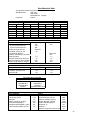
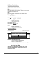
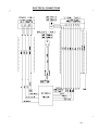
COOLING WATER SEALING & FLOW TEST CIRCUIT
C electric valve
water inle t
E air flow meter
F pressure meter
SPINDLE
in
shuttle
valve
D electric valve
water outlet
out
air inlet
air outlet
A electric valve
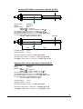
FLOW TEST CIRCUIT
B electric valve
L
main pressure
H
manual pressure
regulator
I
spindle air
pressure
G
electric valve
J
inlet air flow
K
outlet air flow
SPINDLE
AIR IN
AIR OUT
air outlet
inlet
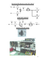
SENSOR PRESSURE TUNING
32
FAILURE – CAUSE - PREVENTION
Cause
Prevention
Failure
The shaft doesn’t
rotate freely.
There is dirt or oil in
bearing gap
Low air pressure
Air bearings are
damaged after crash
-
Low water flow
High temperature of
income coolant
water
-
Water flow 3 – 5 lpm.
Water temperature 25C max.
-
-
Friction in the bearings
-
-
Motor failure
-
-
Driver failure
-
Return the spindle to the
manufacturer for repair.
Return the spindle to the
manufacturer for repair.
Return the driver to the
manufacturer for repair.
Return the control unit
to the manufacturer for repair.
-
Machine control failure
Motor failure
-
-
Friction in the bearings
-
-
Control unit failure
-
-
Driver failure
-
The spindle getting
warm
Spindle shaft
rotated too slowly
with the same
adjustment of
speed control unit
-
-
-
High vibration level
Return the spindle to the
manufacturer for repair.
Return the spindle to the
manufacturer for repair.
Return the control unit
to the manufacturer for
repair.
Return the driver to the
manufacturer for repair.
The shaft’s balancing
has changed
Balance of wheel
mount was changed
There is dirt on air
cover area of the shaft
-
Check that spindle shaft is not
damaged
-
Change the wheel mount
-
Clean the air cover area of the
shaft from dirt
Motor failure
Electrical connections
problem (see above)
-
Return the spindle to the
manufacturer.
Check electrical connections
-
Incorrectly connected
phases
-
Connect phases according
to diagram.
-
Incorrectly connected
phases
-
Connect phases according
to diagram.
-
Incorrectly connected
phases
-
-
Hall sensors are
incorrectly connected.
Connect phases according
to diagram.
Connect Hall sensors
correctly according to diagram
-
The shaft rotates
freely, but the
spindle does not
turn, vibrates or
turns too quickly.
The shaft rotates
freely, but after
starting it vibrates.
Spindle shaft’s
speed is sharply
increased
immediately after
starting and in this
case it’s impossible
to adjust it.
The shaft rotates
freely, but the
spindle does not
turn
Check the air pressure and air
cleaner according to spec.
conditions
Air pressure must be 5 Bar.
Return the spindle to the
manufacturer for repair
-
-
-
33
The shaft rotates in
air bearings, but not
freely, in this case
air pressure is
normal.
-
Air ventilation hole
(AO) of spindle is
closed by dirt, or
sealed, or used small
inlet pipe to air out, or
this pipe is damaged.
-
Air ventilation hole (Air
out) of brushes sensor
(BV) is closed by dirt,
or sealed, or used
small inlet pipe to air
out, or this pipe is
damaged.
Brushes are too short
Electrical connections
problem
- Check spindle’s air outlet
-
Contact resistance
of the sensor more
than 10 KΩ
-
Short circuit
between the
brushes
-
-
There is conductive
Carbon powder in the
contact area of the
brushes
Short circuit in brushes
cable
Check brushes ventilation
-
Replace the brushes
Check electrical connections
-
Clean the brushes area.
Check brushes ventilation
Check the brushes cable
34