1
SERVICE MANUAL
LN-9240-02.1
(Replaces LLN-9240-02.1)
January - 2013
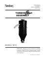
TURBODISK
ASSEMBLY
MODELS: 78715
IMPORTANT: Before using this equipment, carefully
read SAFETY PRECAUTIONS, starting on page 1, and all
instructions in this manual. Keep this Service Manual for
future reference.
Service Manual Price: $50.00 (U.S.)
Turbodisk 2 - Contents
CONTENTS
SAFETY:
PAGE
1-7
SAFETY PRECAUTIONS.........................................................
HAZARDS / SAFEGUARDS.....................................................
GENERAL SAFETY GUIDELINES...........................................
1
2
5
INTRODUCTION:
8-11
FEATURES................................................................................
GENERAL DESCRIPTION.......................................................
SPECIFICATIONS.....................................................................
TYPICAL SPEED CHART (RPM'S)..........................................
8
8
9
10
INSTALLATION:
12-15
EQUIPMENT..............................................................................
AIR CONTROL..........................................................................
MOUNTING................................................................................
INTERLOCKS............................................................................
TYPICAL TURBODISK 2 DRIVE AIR SYSTEM & AIR LOGIC CONTROL
PANEL........................................................
UPPER TURBODISK 2 BULKHEAD PLATE...........................
TURBODISK 2 SIGNAL / PORT IDENTIFICATION TABLE...
12
12
12
12
OPERATION:
16-19
COATING MATERIALS.............................................................
FLUID FLOW CONTROL..........................................................
FLUID VALVE CONTROL.........................................................
FLUID & AIR PRESSURE REQUIREMENTS..........................
TURBINE SPEED......................................................................
ELECTROSTATIC VOLTAGE..................................................
TARGET DISTANCE.................................................................
16
16
17
17
18
19
19
MAINTENANCE:
20-33
GENERAL..................................................................................
CLEANING PROCEDURES.....................................................
VIBRATION NOISE...................................................................
TURBINE REPAIR & REBUILD...............................................
VALVES & REGULATORS.......................................................
PREVENTIVE MAINTENANCE................................................
DISASSEMBLY PROCEDURES..............................................
TROUBLESHOOTING GUIDE.................................................
NO VALVE APPLICATION SCHEMATIC................................
3-WAY VALVE APPLICATION SCHEMATIC..........................
TRIGGER / DUMP w/REGULATOR SCHEMATIC.................
TRIGGER / DUMP w/REGULATOR (DR-1) SCHEMATIC.....
20
20
22
22
22
22
23
28
30
31
32
33
LN-9240-02.1
13
14
15
(CONTINUED ON NEXT PAGE)
Turbodisk 2 - Contents
PARTS IDENTIFICATION:
PAGE
34-69
TURBODISK 2 ASSY MODEL IDENTIFICATION...................
34
TURBODISK 2 ASSY, NO VALVES / PARTS LIST................
38
TURBODISK 2 ASSY, 3-WAY VALVE / PARTS LIST.............
40
TURBODISK 2 ASSY, TRIGGER & DUMP VALVE W/FLUID REGULATOR
/ PARTS LIST....................................................
42
TURBODISK 2 ASSY, TRIGGER & DUMP VALVE W/DR-1 FLUID REGULATOR / PARTS LIST........................................
44
LOWER TURBODISK 2 FLUID CONTROL ASSEMBLY / PARTS LIST........
......................................................................
46
UPPER TURBODISK 2 BULKHEAD PLATE & FAIRING MOUNTING /
PARTS LIST.......................................................
48
FLUID SUPPLY LINE PACKAGE / PARTS LIST....................
50
3-WAY VALVE ASSY / PARTS LIST........................................
52
HIGH FLOW FLUID REGULATOR ASSY / PARTS LIST.......
54
DR-1 FLUID REGULATOR ASSY / PARTS LIST...................
56
DR-1 FLUID REGULATOR ASSY / PARTS LIST...................
58
TURBODISK 2 AIR HEATER / PARTS LIST...........................
60
TURBODISK 2 QUICK RELEASE FAIRING ASSY /
PARTS LIST..............................................................................
62
TRIGGER & DUMP VALVE ASSY / PARTS LIST...................
64
BULKHEAD PLATE FITTING LAYOUT / PARTS LIST...........
66
TURBODISK 2 AIR TURBINE ASSY / PARTS LIST...............
68
WARRANTY POLICIES:
70
LIMITED WARRANTY...............................................................
70
APPENDIX:
71-74
PAINT AND SOLVENT SPECIFICATIONS.............................
VISCOSITY CONVERSION CHART........................................
VOLUMETRIC CONTENT OF HOSE OR TUBE.....................
71
72
74
LN-9240-02.1
Turbodisk 2 - Safety
SAFETY
SAFETY PRECAUTIONS
Before operating, maintaining or servicing any
Ransburg electrostatic coating system, read and
understand all of the technical and safety literature
for your Ransburg products. This manual contains
information that is important for you to know and
understand. This information relates to USER SAFETY
and PREVENTING EQUIPMENT PROBLEMS. To help
you recognize this information, we use the following
symbols. Please pay particular attention to these
sections.
A WARNING! states information to alert you to a
situation that might cause serious injury if instructions
are not followed.
A CAUTION! states information that tells how to
prevent damage to equipment or how to avoid a
situation that might cause minor injury.
A NOTE is information relevant to the procedure in
progress.
While this manual lists standard specifications and
service procedures, some minor deviations may be
found between this literature and your equipment.
Differences in local codes and plant requirements,
material delivery requirements, etc., make such
variations inevitable. Compare this manual with
your system installation drawings and appropriate
Ransburg equipment manuals to reconcile such
differences.
!
WARNING
> The user MUST read and be familiar with the
Safety Section in this manual and the Ransburg
safety literature therein identified.
> This manual MUST be read and thoroughly
understood by ALL personnel who operate, clean
or maintain this equipment! Special care should
be taken to ensure that the WARNINGS and safety
requirements for operating and servicing the
equipment are followed. The user should be
aware of and adhere to ALL local building and fire
codes and ordinances as well as NFPA 33 SAFETY
STANDARD, 2000 EDITION, prior to installing,
operating, and/or servicing this equipment.
!
WARNING
> The hazards shown on the following page may
occur during the normal use of this equipment.
Please read the hazard chart beginning on page
2.
Careful study and continued use of this manual will
provide a better understanding of the equipment and
process, resulting in more efficient operation, longer
trouble-free service and faster, easier troubleshooting.
If you do not have the manuals and safety literature
for your Ransburg system, contact your local Ransburg
representative or Ransburg.
LN-9240-02.1
1
Turbodisk 2 - Safety
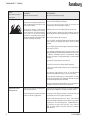
AREA
Tells where hazards
may occur.
Spray Area
HAZARD
SAFEGUARDS
Tells what the hazard is.
Tells how to avoid the hazard.
Fire Hazard
Fire extinguishing equipment must be present in the
spray area and tested periodically.
Improper or inadequate opera-tion
and maintenance procedures will Spray areas must be kept clean to prevent the
cause a fire hazard.
accumulation of combustible residues.
Protection against inadvertent
arcing that is capable of causing
fire or explosion is lost if any safety
interlocks are disabled during
operation. Frequent power supply
shutdown indicates a problem in the
system requiring correction.
Smoking must never be allowed in the spray area.
The high voltage supplied to the atomizer must be
turned off prior to cleaning, flushing or maintenance.
When using solvents for cleaning:
Those used for equipment flushing should have flash
points equal to or higher than those of the coating
material.
Those used for general cleaning must have flash points
above 100oF (37.8oC).
Spray booth ventilation must be kept at the rates
required by NFPA 33, 2000 Edition, OSHA and local codes.
In addition, ventilation must be maintained during
cleaning operations using flammable or combustible
solvents.
Electrostatic arcing must be prevented.
Test only in areas free of combustible material.
Testing may require high voltage to be on, but only as
instructed.
Non-factory replacement parts or unauthorized
equipment modifications may cause fire or injury.
If used, the key switch bypass is intended for use only
during setup operations. Production should never be
done with safety interlocks disabled.
Never use equipment intended for use in waterborne
installations to spray solvent based materials.
General Use and
Maintenance
Improper operation or maintenance Personnel must be given training in accordance with the
may create a hazard.
requirements of NFPA 33, Chapter 16, 2000 edition.
Personnel must be properly trained Instructions and safety precautions must be read and
in the use of this equipment.
understood prior to using this equipment.
Comply with appropriate local, state, and national
codes governing ventilation, fire protection, operation
maintenance, and housekeeping. OSHA references
are Sections 1910.94 and 1910.107. Also refer to
NFPA 33, 2000 edition and your insurance company
requirements.
2
LN-9240-02.1
Turbodisk 2 - Safety
AREA
Tells where hazards
may occur.
HAZARD
SAFEGUARDS
Tells what the hazard is.
Tells how to avoid the hazard.
Electrical Equipment High voltage equipment is utilized. The power supply, optional remote control cabinet, and
Arcing in areas of flammable or
combustible materials may occur.
Personnel are exposed to high
voltage during operation and
maintenance.
all other electrical equipment must be located outside
Class I or II, Division 1 and 2 hazardous areas. Refer to
NFPA No. 33, 2000 Edition.
Turn the power supply OFF before working on the
equipment.
Protection against inadvertent
arcing that may cause a fire or Test only in areas free of flammable or combustible
explosion is lost if safety circuits are material.
disabled during operation.
Testing may require high voltage to be on, but only as
Frequent power supply shutdown instructed.
indicates a problem in the system
which requires correction.
Production should never be done with the safety circuits
disabled.
An electrical arc can ignite coating
materials and cause a fire or Before turning the high voltage on, make sure no objects
explosion.
are within the sparking distance.
Explosion Hazard /
Incompatible
Materials
Halogenated hydrocarbon solvents
for example: methylene chloride
and 1,1,1,-Trichloro-ethane are not
chemically compatible with the
aluminum that might be used in
many system components. The
chemical reaction caused by these
solvents reacting with aluminum
can become violent and lead to an
equipment explosion.
Toxic Substances
Certain material may be harmful if Follow the requirements of the Material Safety Data
inhaled, or if there is contact with Sheet supplied by coating material manufacturer.
the skin.
Adequate exhaust must be provided to keep the air free
of accumulations of toxic materials.
Aluminum is widely used in other spray application
equipment - such as material pumps, regulators,
triggering valves, etc. Halogenated hydrocarbon
solvents must never be used with aluminum equipment
during spraying, flushing, or cleaning. Read the label
or data sheet for the material you intend to spray. If
in doubt as to whether or not a coating or cleaning
material is compatible, contact your material supplier.
Any other type of solvent may be used with aluminum
equipment.
Use a mask or respirator whenever there is a chance
of inhaling sprayed materials. The mask must be
compatible with the material being sprayed and its
concentration. Equipment must be as prescribed by
an industrial hygienist or safety expert, and be NIOSH
approved.
LN-9240-02.1
3
Turbodisk 2 - Safety
AREA
Tells where hazards
may occur.
Spray Area / High
Voltage Equipment
HAZARD
SAFEGUARDS
Tells what the hazard is.
Tells how to avoid the hazard.
There is a high voltage device that
can induce an electrical charge
on ungrounded objects which
is capable of igniting coating
materials.
Parts being sprayed must be supported on conveyors
or hangers and be grounded. The resistance between
the part and ground must not exceed 1 megohm.
Inadequate grounding will cause
a spark hazard. A spark can ignite
many coating materials and cause
a fire or explosion.
All electrically conductive objects in the spray area, with
the exception of those objects required by the process
to be at high voltage, must be grounded.
Any person working in the spray area must be
grounded.
Unless specifically approved for use in hazardous
locations, the power supply and other electrical control
equipment must not be used in Class 1, Division 1 or
2 locations.
Personnel Safety /
Mechanical Hazards
4
The disk atomizer can rotate at
speeds up to 40,000 RPM. At these
speeds, the edge of the applicator
can easily cut into skin. Loose
articles can also be caught by the
rotating disk.
Personnel must stay clear of the disk whenever it is
rotating.
Before touching the disk, the turbine air must be shut
off.
If the disk has been rotating, allow at least three minutes
for it to come to a complete stop before touching it.
LN-9240-02.1
Turbodisk 2 - Safety
GENERAL SAFETY GUIDELINES
• The articles being coated MUST be grounded at all
times.
!
WARNING
>
The simple safety measures outlined here
are vital. Failure to observe them could cause a
spark capable of starting a fire.
• All components of the applicator system (except the
atomizing head) MUST be grounded at all times.
• All contact points MUST be free of any accumulation
of nonconductive residue.
• All electrically conductive objects, especially solvent
containers within the spray area, MUST be either
removed or grounded.
Any tool, if used improperly, can be dangerous. Safety
is ultimately the responsibility of those using a tool.
In like manner, safe operation of electrostatic coating processes is the responsibility of those who use
such processes and those who operate electrostatic
coating equipment. Procedures to be followed on
conducting electrostatic coating operations safely are
outlined in the Ransburg brochure IL-247: "Operating
Your Electrostatic Coating System Safely". Additional
copies are available from Ransburg upon request.
All personnel connected with coating operations
should read and understand this brochure. It is
most important that the equipment operators and
supervisory personnel understand the requirements
for safe operation.
!
>
WARNING
If ANY symptom of improper operation
occurs, suspend use of the unit until the problem
has been diagnosed and corrected. See the
appropriate "Troubleshooting Guide" or contact
your Ransburg representative.
LN-9240-02.1
Additional cards summarizing these safety requirements are available from Ransburg on request. These
cards should be posted in the spraying area so that
they can be readily referred to and serve as a reminder
to personnel in that area of responsibility. Additional
copies of the sign SL-00-07: "Cleaning Safety Requirements" are available upon request.
Each user should examine his own coating operation,
develop his own safety program, and ensure that his
workers follow correct procedures. Ransburg hopes
that the information it provides is helpful to the user
in establishing such a program.
In addition to the available cards, labels, brochures,
and service manuals, the user should consult other
standards and recognized safety authorities. Section
1910.107 of the regulations established under the
Occupational Safety and Health Act [OSHA] apply to
spray finishing operations. Paragraph (i) specifically
applies to electrostatic hand spraying equipment.
NFPA No. 33 "Spray Application", is another standard
for spray painting operations. Chapters 9, 10, and
13 are specifically applicable to electrostatic coating. Copies of NFPA No. 33 are available from the
National Fire Protection Association, Batterymarch
Park, Quincy, Mass. 02269 (at nominal cost).
The National Fire Protection Association also publishes standards other than NFPA No. 33 relating to
the control of fire hazards. NFPA No. 33 specifically
refers to the following bulletins of the National Fire
Protection Association as applicable to coating operations:
NFPA No.63: Dust Explosion, Industrial Plants
NFPA No.70: National Electrical Code
NFPA No.86A: Ovens and Furnaces
NFPA No.91: Blower and Exhaust Systems
NFPA No.654: Dust Explosions, Plastics Industry
NFPA No.77: Static Electricity, also contains much
useful information. Copies of these brochures will be
helpful in arriving at a program for safe operation.
Local codes and authorities also have standards to be
followed in the operation of your spray equipment.
Your insurance carrier will be helpful in answering
questions that arise in your development of spray
coating procedures.
5
Turbodisk 2 - Safety
All personnel MUST read and understand the
following Ransburg Safety Publications:
IL-247: Operating Your Electrostatic Coating System
Safely SL-77-01: Personnel Grounding
Ransburg also suggests that all personnel read the
HEW publication "Spray Painting: Good Practices for
Employees", number (NIOSH) 78-178 available from
the regional NIOSH office or the U.S. Government
Printing Office.
NIOSH and OSHA regional offices can provide
information on OCCUPATIONAL SAFETY AND
HEALTH ACT, including questions on standards
interpretations, voluntary compliance information,
copies of the OSHA Standards, OSHA Act, Employee
Rights Posting Notice and Publications.
• All personnel should read and understand local
codes, appropriate NFPA bulletins, OSHA Act of
1970, and this service manual.
• Personnel working in the spray area MUST be
adequately grounded. Insulated shoes such as
rubber, composition, or cork soles should NOT
be worn unless an alternate grounding method
is provided. (See Ransburg Bulletin SL-77-01,
"Personnel Grounding".)
WARNING
>
ALWAYS turn power supply OFF prior to
cleaning or working on equipment.
> ENSURE that the grounding hook has been
properly secured to the motor housing.
• Personnel working on applicators MUST always
be sure that the high voltage is off, the rotator has
stopped and that the grounding hook has been
properly secured to the motor housing.
6
• Articles being painted MUST be grounded at
ALL times. Paint MUST NEVER be permitted to
accumulate on workholders, particularly on points
where workholders touch conveyor. Hooks MUST
be clean to ensure proper contact. It is advisable to
have extra sets of workholders to enable cleaning of
the sets not being used at regular intervals. Areas
of hanger contact should be sharp points or edges
where possible.
• All electrically conductive objects within the
spray area (including spray booth, paint tank, and
conveyor) MUST BE GROUNDED. This requirement
applies to the solvent safety container, paint
containers, wash cans, and all other objects in the
area.
Ventilation
Personnel
!
Parts
We recommend interlocking the ventilation with the
spraying equipment to ensure proper ventilation
when equipment is in operation. See NFPA Bulletin
No. 33.
Housekeeping
• Good housekeeping is essential to safe operation.
Clean-up and maintenance schedules should be
established by the user, based on observations of
the initial production operations. Maintenance and
safety cards should be posted in clear view of the
operator.
• Normal fire protection measures are required.
These include proper storage of paints, solvents,
and waste, plus ready access to fire extinguishing
equipment. For details, consult NFPA Bulletins No.
30, 33, 70 and 77, your local fire codes, local paint
equipment standards, OSHA Act of 1970, and your
insurance carrier’s recommendations.
Floor Covering and Masking
If it is necessary to cover booth flooring, Ransburg
suggests that the user employ a material which will
NOT support combustion, such as Spark Gard Grade
BWA-100.
LN-9240-02.1
Turbodisk 2 - Safety
Halogenated Hydrocarbons
!
NOTES:
WARNING
>
A chemical reaction, resulting in the
possibility of a pressure EXPLOSION, may occur
if 1,1,1-Trichloroehtane, Methylene Chloride, or
other Halogenated Hydrocarbon solvents are
used in PRESSURIZABLE FLUID SYSTEMS having
ALUMINUM or GALVANIZED WETTED PARTS.
Such an explosion could cause DEATH, serious
BODILY INJURY, and/or substantial property
damage. See Ransburg Bulletins:
SL-81-05: HHC Explosion Hazard Danger Sign
SL-81-08: HHC Explosion Hazard Safety Bulletin
Consult your fluid supplier to determine the
chemical content of your solvents.
LN-9240-02.1
7
Turbodisk 2 - Introduction
INTRODUCTION
FEATURES
GENERAL DESCRIPTION
Features which make the TurbodiskTM 2 Applicator
advantageous for use in electrostatic applications
include:
The Turbodisk 2 Applicator, because of it's high
rotational speed, produces finer atomization,
improved quality, and higher transfer efficiency with
any of the wide variety of coating materials (such
as waterborne and high solids) used in production
finishing operations. It's speed is controlled by varying
the drive air. The applicator assembly is designed for
use on vertical overhead mounted reciprocators.
• Proven turbine motor reliability.
• Patented serrated edge conical disk provides
excellent atomization quality at minimal rotational
speeds.
• Aerodynamic fairing design for ease of cleaning of
external surfaces.
• Speed readout (or control) uses reliable magnetic
pickup for fiber-optic transmission of rotational
speed data. (optional)
• A majority of all assembly components which
come in contact with the fluid material are made
of either stainless steel or, which is impervious to
most fluids.
• Negligible maintenance down time. With the quick
disconnect feature, the lower Turbodisk 2 fluid
section can be exchanged in minimal time for off
line maintenance.
• Quick disconnect feature allows for other fluid
control assemblies to be incorporated when
desired.
• The easily removable lower fairing, turbine air motor
assembly, and the externally mounted regulators
and fluid valves, make off line maintenance more
efficient and economical.
• Control air lines are color coded for ease of
identification.
Quick Disconnect
-REFER TO FIGURES 16, 17, & 26
The Turbodisk 2 Applicator is a quick disconnect
design that allows the lower fluid section that carries
all the fluid/ air controls to be separated from the
upper section carrying the tubing supply lines. The
incoming air lines, fluid lines, high voltage cable,
and fiber optic cable are connected to the fittings
provided on the upper fixed bulkhead plate. Each
bulkhead plate (upper and lower) utilizes special
male and female fittings with o-rings that seal the
fluid and air line passages when both sections are
assembled together. Two latching mechanisms have
been incorporated into the design allowing the lower
section to be supported while the operator tightens or
loosens the retaining screws that hold the upper and
lower sections together. Alignment arrows engraved
into the side of the bulkhead plates provide for quick
visual assembly orientation.
Conical Disk Assembly
The Turbodisk 2 Applicator uses conical disk
assemblies that are made from high grade aluminum
construction and are force balanced to .10 grams•in or
better. With the patented serrated edge, these disks
come in sizes of 6, 9, and 12 inch diameters.
• Higher fluid delivery rates can be achieved using a
dual feed fluid system.
• High flow regulators and fluid valves provide for
simultaneous paint push out while solvent washes
the feed tube and disk.
8
LN-9240-02.1
Turbodisk 2 - Introduction
Turbodisk 2 Fairing
SPECIFICATIONS
The Turbodisk 2 Applicator fairing is required for
safe operation. The two piece fairing provides high
voltage isolation from the metal rotator assembly
and valve components, as well as ease of cleaning
and maintenance. Provided on the fairing are (4)
draw latches which allow for easy on/off removal of
the lower fairing.
Mechanical
-REFER TO FIGURE 24
Turbine Speed:
Variable to 40,000 rpm max. (6" conical disk)
Turbine Type:
Ball Bearing
Weight:
57 lbs. (approximately)
Length: 36 in.
Diameter:
13.25 in.
Turbine Air:
At max. speed (40krpm), requires 103.1 psi and
61.1 scfm, unloaded
(see Figure 1)
Four paint valve options in single or dual feed
applications are available:
Fluid Pressure
Inlet:
See Figure 4
• No Valves (refer to Figures 7,12,18)
• 3-Way On/Off Valve (refer to Figures 8,13,19)
• Trigger and Dump Valve with High Flow Regulator
(refer to Figures 9,14,20,25)
• Trigger and Dump Valve with Low Flow
Regulator (refer to Figures 10,15,21,22,25)
Single Fluid Flow Range:
Waterborne:
To 1,200 cc/min.
Solvent Base:
To 1,500 cc/min.
High Solids:
To 1,000 cc/min. (80%+)
Air Inlet Trigger/
Dump:
70-100 psi
Power Supply and Controls
Air Pilot for Fluid
Pressure:
See Figure 4
!
WARNING
>
Both sections of the fairing to be in place
when the Turbodisk 2 is in operation or when
high voltage is supplied to the applicator.
Paint Valve Options
In the system, the high voltage is supplied to the
Turbodisk 2 by either the MicroPak™ Industrial power
supply system or a Voltage Master™ series power
supply.
The MicroPak Industrial power supply uses
proven high voltage generator technology that
is microprocessor controlled for diagnostics and
communication. The controller is packaged in
standard rack mounted Eurocard format for easy
access and system integration.
The Voltage Master™ power supplies are general
purpose heavy duty power supplies with years of
proven reliability. They have variable voltage control,
many safety features, and remote analog voltage
control capabilities.
LN-9240-02.1
Electrical
Power Supply or Type:
MicroPakTM Industrial
Voltage MasterTM
Charging Method:
Direct
Input Voltage:
0-100 kV
Turbine Speed
Control or Monitor:
PulseTrackTM
(Optional)
9
Turbodisk 2 - Introduction
NOTES:
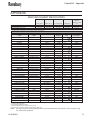
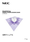
TYPICAL SPEED CHART (RPM's)
-REFER TO FIGURES 1 & 23
The following represents data collected under lab
conditions. Flow meters were installed on each of
the two 3/8 I.D. heated air lines used to supply the
Turbodisk 2 turbine motor. The airflow through
each flow meter was recorded and added together
to obtain the total air flow through the system. The
speed of the disk was monitored through the means
of a PulseTrack™ system. The air heater was set at 120
degrees during all data collection.
Rotational speeds are unloaded and can be expected
to drop 20 to 30% when under a fluid load condition.
Heated turbine air increases efficiency of motor up
to 10%. This chart should be used as a guide ONLY.
Speeds will vary due to rotator wear, tubing size or
lengths, etc.
NOTE
> Never run disk over it's maximum safe
operating speed.
10
LN-9240-02.1
Turbodisk 2 - Introduction
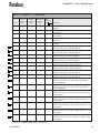
TYPICAL SPEED CHART - 10 HOLE ORIFICE PLATE
6" Conical Disk
Disk Speed
(RPM)
Supply Air
Pressure (PSI)
Air Flow #1
(SLPM)
Air Flow #2
(SLPM)
Total Air Flow
(SLPM)
Total Air Flow
(SCFM)
5,000
10,000
15,000
20,000
25,000
30,000
35,000
40,000
6.6
10.5
18.2
27.8
40.4
56.3
76.4
103.1
140
190
260
340
440
560
730
930
100
140
200
260
350
460
610
800
240
330
460
600
790
1,020
1,340
1,730
8.5
11.7
16.2
21.2
27.9
36.0
47.3
61.1
Disk Speed
(RPM)
Supply Air
Pressure (PSI)
Air Flow #1
(SLPM)
Air Flow #2
(SLPM)
Total Air Flow
(SLPM)
Total Air Flow
(SCFM)
5,000
10,000
13,000
16,000
19,000
22,000
11.3
26
39.5
55.4
79.8
102
200
330
430
560
760
930
140
250
340
460
640
800
340
580
770
1,020
1,400
1,730
12.0
20.5
27.2
36.0
49.4
61.1
Disk Speed
(RPM)
Supply Air
Pressure (PSI)
Air Flow #1
(SLPM)
Air Flow #2
(SLPM)
Total Air Flow
(SLPM)
Total Air Flow
(SCFM)
2,000
4,000
6,000
8,000
10,000
12,000
12,500
8.7
18.6
31.0
48.3
68.5
95.8
102.0
170
270
370
500
670
880
930
120
200
290
400
560
750
780
290
470
660
900
1,230
1,630
1,710
10.2
16.6
23.3
31.8
43.4
57.6
60.4
9" Conical Disk
12" Conical Disk
Figure 1: Typical Speed Chart - 10 Hole Orifice Plate
LN-9240-02.1
11
Turbodisk 2 - Installation
INSTALLATION
EQUIPMENT
MOUNTING
This system should be installed by, or under the
supervision of an Ransburg representative. Should the
need arise to replace any component assembly within
the system, contact your Ransburg representative.
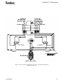
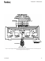
-REFER TO FIGURE 17 & 24
This manual concerns normal operation, maintenance,
and service of the specified applicator assemblies. The
air and fluid connections vary with different models
and installations. This manual deals primarily with
those at, or within the assembly.
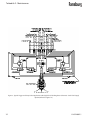
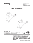
AIR CONTROL
-REFER TO FIGURE 2
Air control of the applicator is from a standard
Ransburg air logic panel, which includes two filters
(one 40 micron filter located at the air logic station
and one 5 micron filter located at the inlet of the inline air heater panel). Clean, dry factory air must be
provided to the inlet filter of the air logic station via
a minimum 1/4-inch I.D. pipe and to the inlet filter of
the heater panel via a minimum 3/4-inch I.D. pipe.
12
The Turbodisk 2 assembly is mounted on the
reciprocator using (4) 5/16-18 screws provided on
the ram flange. Loosening (2) 1/4-20 screws on the
same ram flange will allow the assembly to rotate.
Position the Turbodisk 2 assembly so that the strain
relief boot is positioned toward the incoming fluid
and air lines and retighten.
Remove lower fairing by releasing the (4) quick release
draw latches. Thread all the required air, high voltage,
fiber optic, and fluid service lines through the strain
relief boot. The strain relief boot may have to be cut
larger in order to feed all the lines through. Refer to the
78718 assembly/schematic diagram for connection
reference to upper bulkhead plate.
Reinstall lower fairing. Install conical disk and torque
to 50-60 lb•in.
INTERLOCKS
Flow of coating material should be locked out unless
all of the following conditions are met:
1.
Booth exhaust is turned on.
2.
The turbine is spinning.
3.
High voltage is on or in the bypass mode.
LN-9240-02.1
Turbodisk 2 - Installation
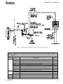
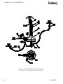
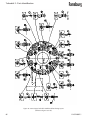
Figure 2: Typical Turbodisk 2 Drive Air System and Air Logic Control Panel
TYPICAL TURBODISK 2 DRIVE AIR SYSTEM & AIR LOGIC CONTROL PANEL - PARTS
LIST (Figure 2)
Item #
1
2
3
4
5
LN-9240-02.1
Part #
78170-00
SSP-6439
SSV-8221
7819-16
LS0147
7596-12
GA-316
41-FP-1021
HAF-503
78166-00
78164-00
78165-00
20222-00
78176-01
SSM-5805
Description
Regulator Assembly, Turbodisk 2 Drive Air (Includes the Following:)
Elbow, 1/4 O.D. Tube x 1/4 NPT Male Swivel
Regulator, 1/2 NPT Ported, Air Piloted
Nipple, 1/2 NPT x 1.5 Long, Brass Pipe
Regulator, 1" Ported, Manual Adj. Air, 0-125 psi, 250 CFM
Bushing, 1" NPT x 1/2 NPT, Brass
Gauge, 0-160 psig, 1/4 NPT, Air
Nipple, 1" NPT x 3/4 NPT, Hex Reducing
Air Filter, 3/4 NPT
Hose Assembly, Compressed Air (Includes the Following:)
Hose, 3/4" I.D., Push-Loc Air
Fitting, Female SAE 45o Swivel x 3/4" I.D. Hose
Air Heater Assembly
Tubing, 1/2" O.D. x .375" I.D., Green Nylon
Air Filter, 1/4 NPT
Qty
1
2
1
1
1
1
1
1
1
1
5 ft.
2
1
To Suit
1
13
Turbodisk 2 - Installation
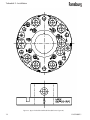
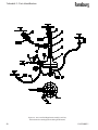
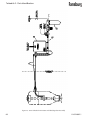
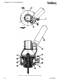
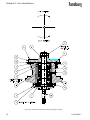
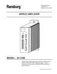
Figure 3a: Upper Turbodisk 2 Bulkhead Plate (Reference Figure 26)
14
LN-9240-02.1
Turbodisk 2 - Installation
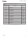
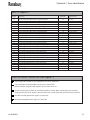
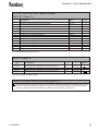
TURBODISK 2 SIGNAL/PORT IDENTIFICATION TABLE
(Figure 3b)
Designation as Marked
on Bulkhead
F.O
HV
P1D
P1DL
R1H
R1L
P1S
P1R
P1T
P2D
P2DL
R2H
R2L
P2S
P2R
P2T
S1.IN
S2.IN
T.A1
T.A2
Description
Fiber Optic Cable
High Voltage Cable
Paint #1 Dump
Paint #1 Dump Line
Regulator #1 High
Regulator #1 Low
Paint #1 Supply Line
Paint #1 Return Line
Paint #1 Trigger
Paint #2 Dump
Paint #2 Dump Line
Regulator #2 High
Regulator #2 Low
Paint #2 Supply Line
Paint #2 Return Line
Paint #2 Trigger
Solvent #1 Supply
Solvent #2 Supply
Turbine Air #1
Turbine Air #2
Tubing Color
Natural
Natural
Red
Natural
Orange
Yellow
Natural
Natural
Green
Black
Natural
Silver
Blue
Natural
Natural
Natural
Natural
Natural
Green
Green
Figure 3b: Turbodisk 2 Signal/Port Identification Table
LN-9240-02.1
15
Turbodisk 2 - Operation
OPERATION
!
CAUTION
>
Fluids and lubricants used in this system
must contain NO silicones!
> Do NOT operate the unit without an atomizer
disk! Without a disk, overspeed, resulting in
premature bearing failure, is possible.
>
The air supplied to the motor must be dry,
clean and free of oil or moisture. The atmospheric
dew point should be 10oF or less. The air heater
used should be adjusted only high enough to
prevent condensation from forming on the motor
housing or at the exhaust port.
!
WARNING
>
Operators must be fully trained in safe
operation of electrostatic equipment. Operators
must read all instructions and safety precautions
prior to using this equipment (See NFPA 33,
Chapter 16).
As with any spray finishing system, operation of the
Turbodisk 2 involves properly setting the operating
parameters to obtain the best finish quality for the
coating material being sprayed, while maintaining
correct operation and reliability of the equipment
used. Adjustments to operating parameters,
which cover spraying, cleaning and on/off control,
include:
• Fluid Type
• Fluid Flow Rate
• Turbine Speed
• Electrostatic Voltage
• Target Distance
COATING MATERIALS
The Turbodisk 2 can be used with a broad range
of coating material conductivities. However, with
waterborne paints, it may be necessary to isolate the
paint supply from ground.
!
WARNING
> Isolated fluid supplies using either waterborne
or highly conductive solvent base coatings can
produce hazardous high voltage discharges
which can cause fires or injury to personnel.
FLUID FLOW CONTROL
-REFER TO FIGURES 19-22
Fluid flow control is dependent on the valve
configuration of the Turbodisk 2. If the Turbodisk 2
is configured with no valves or a 3-way valve, fluid
flow is controlled externally at the paint source. If the
Turbodisk 2 is equipped with a regulator, fluid flow
can be controlled via the air pilot signal. The high
flow and low flow regulators each have procedures
on how to control and deliver consistent fluid flows.
For more information on controlling the fluid delivery
using regulators, refer to that specific manual which
is included with the system.
To check fluid flow rates, the disk must be removed.
See the maintenance section for removal procedure.
The fluid can then be manually triggered to measure
actual flow in a graduated beaker over a specified
time period.
!
WARNING
> Danger of shock and/or personal injury can
occur. Proper grounding procedures, which are
outlined in the Ransburg safety bulletins, must
be followed. Personnel must never work near or
perform work on the turbine when the turbine
is spinning or when high voltage is on.
16
LN-9240-02.1
Turbodisk 2 - Operation
FLUID VALVE CONTROL
Trigger and Dump
-REFER TO FIGURES 4 & 25
The fluid valves in the Turbodisk 2 are actuated by an
air signal. The air pressure must exceed 70 psi to assure
proper actuation of the valve. Applying air to the valve
actuator turns on the fluid flow for that valve.
The trigger valve controls the paint flow to the disk.
When actuated, paint flows through the valve to
the fluid tube. The disk should be spinning at a RPM
speed that is fast enough, (that when fluid is turned
on) to enable the fluid to flow through the disk paint
passage holes and be atomized.
The dump valve controls the paint flow through the
dump line. When actuated, paint flow is directed to the
dump return line. This provides a method of rapidly
removing paint from the incoming line for cleaning
Air Pilot Fluid
and/or color change. Normally, the dump valve is not
actuated at the same time as the paint trigger valve
since the trigger valve is intended to cause the fluid
flow to the disk at the prescribed input pressure.
FLUID & AIR PRESSURE
REQUIREMENTS
-REFER TO FIGURE 4
Fluid and air pressure requirements are dependent
on the fluid trigger valve configuration.
No Valves
3-Way ON/OFF
(18283)
Trigger/Dump
w/High Flow
(70171-04)
Regulator
Trigger/Dump
w/Low Flow
DR-1 (74151)
Regulator
78718-01 thru -10
78718-11 thru -20
78718-21 thru -30
78718-31 thru -xx
------------------
------------------
100 psi max.
100 psi
------------------
120 psi max.
70-100 psi
70-100 psi
------------------
300 psi max.
80-100 psi max.
80-100 psi max.
------------------
30-60 psi max.
30-60 psi max.
30-60 psi max.
Regulator
Air Inlet Trig/
Dump Valve
Fluid Inlet
Pressure
Solvent Inlet
Note: Trigger/dump valves (CCV-403-SS) are rated to 300 psi maximum inlet fluid pressure but are limited to the lower pressure limit of the fluid regulators.
Figure 4: Turbodisk 2 Fluid & Air Pressure Requirements
LN-9240-02.1
17
Turbodisk 2 - Operation
TURBINE SPEED
Turbine speed is determined by the drive air pressure
at the rotary atomizer and fluid flow rate.
Atomizers
-REFER TO FIGURE 5
Turbine speed can be closed loop controlled using
the fiber optic speed transmitter mounted at the back
of the turbine rotator assembly as a speed input to
remote speed controls such as the PulseTrack.
!
> Never operate any disk atomizer in excess of
it's maximum rated speed ("K" number) as listed
in the service manual. Excessive speed may cause
the disk to disintegrate, causing serious damage
and/or injury.
NOTE
>
The disk rotational speed determines
the quality of atomization and can be varied
for different flow rates and viscosities. For
optimum transfer efficiency and spray pattern
control, the disk rotational speed should be
set at the minimum required speed to achieve
proper atomization. Excessive speed reduces
transfer efficiency!
!
WARNING
All atomizers manufactured after April 6, 1982, bear
a “K” number. That number indicates the maximum
safe rotation speed for that series in tens of thousands.
For example:
WARNING
> Do not exceed the maximum rated speed of
9K = 9,000 RPM maximum safe speed, 40K = 40,000 RPM, etc.
If you have an atomizer that does not have a “K”
number, contact your Ransburg representative for
its maximum safe operating speed.
40,000 RPM for the 6 inch conical disk and 27,000
RPM for the 6 inch uni-disk.
TYPICAL MAXIMUM SAFE OPERATING SPEEDS
Atomizer Disk
Part Number
Max. RPM
6" Uni-Disk
8" Uni-Disk
10" Uni-Disk
12" Uni-Disk
6" Conical
9" Conical
12" Conical
19830-06
19830-08
19830-10
19830-12
20485-62
20485-92
20485-12x
27,000
23,000
15,000
15,000
40,000
25,000
20,000
Figure 5: Typical Maximum Safe Operating Speeds
18
LN-9240-02.1
Turbodisk 2 - Operation
ELECTROSTATIC VOLTAGE
NOTES:
In the system, the high voltage is supplied to the
Turbodisk 2 by either the MicroPak Industrial power
supply system or Voltage Master series power
supplies.
The MicroPak Industrial power supply uses
proven high voltage generator technology that
is microprocessor controlled for diagnostics and
communication. The controller is packaged in
standard rack mounted Eurocard format for easy
access and system integration.
The Voltage Master power supplies are general
purpose heavy duty power supplies with years of
proven reliability. They have variable voltage control,
many safety features, and remote analog voltage
control capabilities.
TARGET DISTANCE
The distance between the Turbodisk 2 and the target
will affect the finish quality, penetration and efficiency.
Closer distances give wetter finishes and greater
efficiency, while greater distances give drier finishes.
The recommended normal disk edge to target range
is 12 inches minimum for optimum performance.
LN-9240-02.1
19
Turbodisk 2 - Maintenance
MAINTENANCE
GENERAL
!
Verify daily that the operating parameters have
not varied dramatically. A sudden change or even
a gradual decay in performance could be early
indications of component failure.
Normal maintenance procedures should be
established and recorded at the initial start-up. All
maintenance schedules are subject to variation
based on use. Periodically review these maintenance
schedules as equipment ages and needs change.
CLEANING PROCEDURES
!
WARNING
> Electrical shock and fire hazards can exist
during maintenance. The power supply must be
turned off before entering the spray area. Spray
booth fans should remain on while cleaning
with solvents.
>
Never touch the disk atomizer while it is
spinning. The edge of the disk can easily cut into
human skin, gloves or other materials. Be sure the
disk atomizer has completely stopped spinning
before attempting to touch it. Approximate time
for the disk to stop spinning after turning off the
drive air is about three minutes.
CAUTION
> Do not immerse the Turbodisk 2 assembly
in solvent or other liquids. Turbine components
will be damaged.
> Do not soak the disk in solvent longer than
24 hours.
Internal Fluid Path Cleaning
With the high voltage turned off and the disk spinning,
flush cleaning solvent through the incoming paint
line or through the solvent inlet line. If it is desired to
clean just the face of the disk off, flush solvent through
the solvent inlet. If a color change is required, flush
the entire system. The spinning disk will atomize the
solvent and clean out the disk passages. If equipped,
trigger the dump valve to catch the wasted paint from
the incoming line, then flush the disk with solvent
after closing the dump valve.
NOTE
> Solvent flushing of the system (except
during color change) should be done with
the disk dismounted and with waste solvent
collected in a grounded container.
In addition to the above Warning, which relates to
potential safety hazards, the following information
must be observed to prevent damage to the
equipment.
20
LN-9240-02.1
Turbodisk 2 - Maintenance
External Atomizer Surface Cleaning
!
WARNING
>
To reduce the risk of fire or explosion,
OSHA and NFPA 33 require that solvents used
for exterior cleaning, including disk cleaning
and soaking, be nonflammable (flash points
higher than 100oF/37.8oC). Since electrostatic
equipment is involved, these solvents should
also be nonpolar. Examples of nonflammable,
nonpolar solvents for cleaning are: Amyl acetate,
methyl amyl acetate, high flash naphtha and
mineral spirits.
> Do not use conductive solvents such as MEK to
clean the external surfaces of the Turbodisk 2.
> Never lower the Turbodisk 2 assembly into a
drum for flushing or color changing.
Clean the disk by soaking in an appropriate solvent
to loosen paint residue. Do not soak for more than a
24 hour period. Use a soft cloth to remove the paint
from the surface and a soft bristle brush to remove
paint from the well area. The splash plate may need
to be removed to clean the paint well. The screws
must be retorqued to 24 lb•in after cleaning.
Reinstall the disk and torque the mounting nut to
50-60 lb•in.
!
> Do not attempt to clean the disk edge while
it is rotating. Do not attempt to slow down or
stop the disk by holding a rag or a gloved hand
against the edge. This could cause physical harm
and/or damage to the disk.
!
Disk Cleaning
Normally, the internal cleaning instructions will
suffice to clean the disk. If flushing the disk does not
remove all the residue, the disk may be removed for
hand cleaning. Unscrew mounting nut and remove
the disk by using the supplied disk puller.
Inspection of the disk is required to determine if
wear to the serrated edge or damage has occurred.
Wear can cause a reduction in transfer efficiency and
excessive paint wrap on the atomizer fairing.
NOTE
> The turbine shaft must be held with a
7/16” open end wrench while using the disk
puller.
!
WARNING
CAUTION
>
Do not use abrasive materials which will
scratch or damage the disk. Cleaning pads such
as Scotch-Brite® should not be used.
> Using an atomizer disk with paint buildup may
cause an imbalance. This may result in bearing
damage and turbine failure. This condition
may also stress the disk when operating at high
speeds.
> Before reinstalling the disk onto the shaft,
check and clean the tapered mating surface for
paint residue.
> Care must be taken when mounting the disk
assembly to the motor shaft. The mounting nut
should turn freely for several turns until it fully
bottoms on the disk assembly.
WARNING
> Do not hold disk edge during removal. This
could result in injury.
LN-9240-02.1
21
Turbodisk 2 - Maintenance
VIBRATION NOISE
PREVENTIVE MAINTENANCE
If the Turbodisk 2 is vibrating or making an unusual
loud noise, it may mean that there is an unbalanced
situation or a bearing failure. The disk could have
dried paint or could be damaged. This situation
should be corrected immediately. Do not continue
to operate a noisy turbine.
Before any shutdown or maintenance, the fluid system
should be thoroughly flushed. All cleaning should
be done with a minimum of the appropriate clean
solvent and clean, soft, lint free rags or soft brushes
where indicated.
!
WARNING
> If a disk has been mishandled or there appears
to be damage on the face, DO NOT USE. Serious
injury can result from rotating a defective disk. If
there is a concern about the condition of a disk,
please return it to Ransburg for evaluation.
!
WARNING
> Do not stop disk rotation by using a rag or
gloved hand.
>
Make sure high voltage is off before
approaching applicator.
> Follow proper grounding procedures.
TURBINE REPAIR & REBUILD
-REFER TO FIGURE 27
Turbine field repair or rebuild only after factory
warranty expires. Any attempt to disassemble turbine
during warranty period will void the warranty.
VALVES & REGULATORS
-REFER TO FIGURES 19, 20, 21, & 22
No maintenance is normally required on the valves
or regulator other than flushing with solvent daily.
Visual inspections should be made on the valves
and regulator on a weekly basis. Should the valve
or regulator not function properly, refer to the
individual manuals for troubleshooting and repair
procedures.
!
CAUTION
> Because of the hazard of bearing penetration,
solvents should be used sparingly. They should
never be hosed directly onto the atomizer, motor
housing or fiber optic juncture.
Daily Maintenance
!
WARNING
>
Personnel working on applicators MUST
always be sure that the high voltage is off, the
fluid system is flushed and off, the rotator has
stopped, and that the grounding hook has been
properly secured to the motor housing.
• Clean the atomizer disk, motor housing, fairing,
and as needed, the peripheral equipment with
nonpolar high flash point solvents.
22
LN-9240-02.1
Turbodisk 2 - Maintenance
• To prevent solvent penetration beyond the slinger, a
minimal air pressure of 5 to 10 psi should be applied
to the motor in order to maintain a positive pressure.
The motor should be run at operating speed for
several minutes after cleaning to keep any solvent
that has accumulated at the seals from penetrating
into the motor housing.
DISASSEMBLY PROCEDURES
• Inspect the disk edge and face. If damage exists, DO
NOT USE. Return it to Ransburg for evaluation.
• The disk has stopped rotating.
• Check the fluid feed tube to make sure it is not
rubbing the disk.
Weekly Maintenance
• Follow the normal daily maintenance schedule,
then:
• Monitor rotational speed at the control and verify
it is within 5% of target speed.
• Monitor high voltage output indicated on the power
supply display. Verify with high voltage probe and
meter.
• Remove fairing and clean all internal components:
valves, regulators, and tubing. Check tubing for
evidence of pin-holes, kinks, and abrasions.
• If the muffler needs to cleaned (item is to be solvent
cleaned) remove it from the motor. Clean and dry
the muffler before reinstalling it.
• Check fluid flows by removing the disk and manually
triggering the paint valve. Measure the amount of
fluid in a graduated beaker over a specific time to
determine flow rate.
• Clean and inspect the disk face. Look for wear, which
can cause poor transfer efficiency and excessive
paint wrap on the atomizer fairing. Disk removal,
cleaning and inspection may be done more or less
frequently, depending upon use.
Prior to disassembly, verify the following:
• The atomizer disk, valves and regulator have been
flushed with solvent and purged dry with air.
• The air supply to the trigger valves and regulator
have been turned off.
• The fluid and solvent supply have been turned off
and the pressure has been relieved.
• The high voltage has been turned off and the motor
housing grounded.
Turbine Cartridge Exchange
-REFER TO FIGURE 27
Removal
1.
Remove disk mounting nut by holding the
rotator shaft above the disk with a 7/16" open
end wrench and unscrewing the mounting
nut with a 3/8-inch wrench.
2.
Install the Ransburg 19850-00 disk puller into
disk to remove it.
3.
Unlatch the four fairing draw latches and
carefully remove lower fairing.
4.
The lower fluid section of the Turbodisk 2
Applicator, containing the turbine cartridge,
may now be disconnected for continued off
line removal procedures through means of
the "quick disconnect" feature incorporated
into the unit.
!
WARNING
> Handle the disk with caution. The sharp edge
can cut even though it is not rotating.
LN-9240-02.1
23
Turbodisk 2 - Maintenance
With a 5/16-inch wrench, loosen the six
captive retaining screws used to hold the
upper and lower sections together. Note:
As the last screw releases, the lower unit will
drop only enough to allow for the bulkhead
plates to be separated. The two latching
mechanisms on the bulkhead plates will hold
the unit in place until the operator is ready
to move the lower section to a proper work
place.
Installation
Always check the inside of the motor housing and
clean, if required, with a minimum amount of an
appropriate cleaning solvent and a soft cloth.
1.
Using a 1/16-inch wrench, retract the three
jack screws.
!
CAUTION
>
Lightly lubricate o-rings with petroleum
jelly before assembly. Fit parts with o-rings very
carefully. They must not be allowed to distort,
unseat or break.
5.
Once the lower fluid section is placed in
a stationary condition, the removal of the
cartridge can be continued.
6.
Next remove screws holding the fluid tube
assembly.
2.
With a 7/64-inch wrench, remove six socket
head cap screws, which secures the turbine
cartridge to the motor housing.
With o-rings in place on the nozzle plate and
housing, insert the turbine cartridge into
motor housing.
3.
Secure the rotator assembly to the housing
with six socket head cap screws. Tighten
the screws in sequence until the cartridge
is fully engaged into the housing to prevent
misalignment and possible damage. Torque
to 10 lb•in.
4.
To avoid losing the jack screws during normal
operation, torque to 2-3 lb•in.
7.
8.
Using a 1/16-inch wrench, turn each of the
three jack screws, located next to socket head
cap screw, clockwise not more than one half
turn at a time in sequence to separate the
motor from the housing.
!
CAUTION
>
Failure to perform this step correctly may
result in misalignment and possible damage.
> Use caution in removing cartridge to prevent
it from falling out of the housing.
Turbine Cartridge Service
This cartridge is a precision instrument and should
be handled with care. The bearings are preloaded
to 30 pounds and dynamically balanced to 0.01
grams•in or better.
NOTE
> Bearings used in this cartridge contain
special grease that is available exclusively to
Ransburg. The purchase of replacement bearings from sources other than Ransburg is not
recommended.
Turbine field repair or rebuild ONLY after factory
warranty expires. Any attempt to disassemble turbine
during the warranty period will void the warranty.
24
LN-9240-02.1
Turbodisk 2 - Maintenance
Disassembly
!
-REFER TO FIGURE 28
1.
After turbine cartridge has been removed
from housing, secure the rotating assembly
by inserting a 1/4-inch wrench, which may
be secured in a vise for this procedure, in
the hex socket at the rear end of shaft and
remove slinger with a spanner wrench.
2.
With the 1/4-inch wrench still inserted in the
hex socket at the rear end of shaft, remove hex
nut using a 15/16-inch box end wrench.
3.
Secure a wheel puller tool to turbine rotator.
Rotate the center screw of the tool until the
rotor is free of the shaft. Remove key.
4.
Using a 5/64-inch wrench, remove the six flat
head socket screws which secure bearing
retainer to bearing housing. Remove the
retainer.
5.
Support bearing housing, front face down,
on two parallel supports on the arbor press
table. Press shaft from the housing. Remove
spacer from the shaft.
!
CAUTION
>
The space between the supports must
be greater than the outside diameter of front
bearing.
6.
7.
On the arbor press table, support the
assembled shaft/bearing, front end down, on
the two parallel supports. With the bearing
faces resting on the supports, press the shaft
free of the bearing.
Remove rear bearing, spring, spring retainer
(wave spring washer, and shims in some older
models instead of spring and spring retainer),
and bearing spacer from bearing housing. It
may be necessary to press the bearing from
the housing using a wood or plastic rod or
tool handle inserted through the bore from
the front.
LN-9240-02.1
CAUTION
> Never use a tool that is harder than the part
it is used on.
8.
With a 5/64-inch wrench, remove the six
flat head socket screws from nozzle plate.
Remove the nozzle plate.
9.
Remove all o-rings.
Inspection and Preparation
!
CAUTION
> Failure to observe the following cautions will
result in diminished performance and premature
motor failure.
• Never use any silicone compound in this system!
• Never use any lubrication on the bearings!
• Never use any solvent on the bearings!
• Never exert force on one race of a bearing assembly
that may be transmitted to the other race through
the bearings! Force and resistance must always be
on the same race in order to prevent damage.
• Do not enlarge the nozzle passages during cleaning,
as it will effect performance.
• Always observe the specified torque in tightening
fasteners.
• Clean all parts thoroughly with an appropriate,
clean solvent. Inspect them for wear or damage
and replace as required.
• Check all flow passages for obstruction, particularly
the nozzle plate. Clear as required.
• Discard all bearings and o-rings and replace with
new. Lightly lubricate o-rings with petroleum jelly
before assembly. Fit parts with o-rings very carefully.
They must not be allowed to distort, unseat, or
break.
25
Turbodisk 2 - Maintenance
Assembly
1.
8.
With o-ring in its groove on the rear face of
bearing housing, secure nozzle plate in place
with the six screws.
NOTE
> Torque the screws to 10 lb•in. Do NOT
lubricate o-ring.
2.
Using a press tool device on the arbor press
table, place front bearing over the rear end
of shaft. Insert the shaft into the press tool
rear end down and press the shaft through
the bearing until the bearing seats against
the shoulder on the shaft.
3.
Place bearing housing on the arbor press
table, front face up, resting on two parallel
supports.
4.
Insert the bearing/shaft into the bore of the
bearing housing. With o-ring in place against
it, place bearing retainer over the shaft so
that it rests on the bearing. Place the press
tool, large end down, over the shaft so that it
rests against the bearing retainer. Press until
the bearing seats in the housing.
5.
!
from the assembly MUST be placed into it or the
bearing preload will NOT be correct! Each unit
is individually preloaded. The number of shims
used for this purpose may vary from unit to unit.
It is therefore necessary that the same number
of shims be installed in a repaired unit as were
removed. If more than one unit is serviced at one
time, be SURE that the shims removed from each
unit are returned to that same unit!
9.
NOTE
26
6.
From the rear of the assembly, place bearing
spacer over the shaft and into the bore so
that it seats against the front bearing.
7.
From the rear of the assembly, place spring
and spring retainer over the shaft and into the
bore over the bearing spacer. In some older
models, shims and a wave spring washer are
used in place of the spring and retainer. In
those models, place shims and wave spring
washer over the shaft and into the bore.
CAUTION
> The same number of shims that were removed
Remove the assembly from the press and
secure the retainer with the six screws.
> Torque the screws to 10 lb•in.
With the housing assembly, front face down,
resting on two parallel supports on the arbor
table, place the rear bearing over shaft. Be
sure that o-ring is in place in its groove in
the housing bore. Place the small end of
the press tool over the end of the shaft so
that it rests against the inner face of the
bearing. CAREFULLY press the bearing onto
the shaft.
With the assembly still on the press table,
place the turbine rotor, flanged side up, over
the shaft. Insert key into the key slot in the
shaft, align it with the key slot in the rotor, and
press the rotor down until the key is engaged.
With the small end of the press tool against
the rotor flange, press it onto the shaft until
it seats.
!
CAUTION
>
The outer face of the bearing should be a
slip fit into the bore of the housing. Be careful
that the bearing does not hang up on the outer
edge of the bore during the pressing.
10.
Place hex nut and the 15/16-inch box end
wrench on the rear end of the shaft. Secure
the rotating assembly by inserting a 1/4-inch
wrench, which may be secured in a vise for
this procedure, in the hex socket at the rear
end of the shaft. Secure the nut using the
box end wrench.
LN-9240-02.1
Turbodisk 2 - Maintenance
!
CAUTION
NOTES:
> If the key is not secure or is missing, the unit
will malfunction!
11.
With the shaft still secured from rotation,
screw slinger onto the front end of the shaft
and secure it using a spanner wrench.
NOTE
> Torque the nut to 350 lb•in.
LN-9240-02.1
27
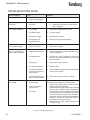
Turbodisk 2 - Maintenance
TROUBLESHOOTING GUIDE
General Problem
Cause
Solution
Fluctuating Pattern
1. Not enough back pressure on regulator.
1. See regulator manual for diagnosis.
Light Coverage on
Some Parts
1. Part hangers, hooks, are not clean.
1 a. Clean hangers.
b. Check ground continuity. (Must be less than 1 Megohm.)
Poor Transfer Efficiency
1. Low voltage.
1. Check disk voltage with H.V. probe.
2. Disk RPM to high.
2. Slow disk speed.
3. Booth flow to high.
3. Reduce booth air flow.
4. Disk edge to part
distance to great.
4. Decrease conveyor loop diameter.
Low Current Readings
1. Dirty H.V. contacts.
1. Clean and/or replace.
High Current Readings /
Power Supply Overloads
1. Target distance to close.
1. Check target distance. Ideal target distance is
12 inches minimum.
2. Conductive paint.
2. Solvent base paint conductivity should be
between .05 and 20 megohms on Ransburg
paint test meter.
3. Fairing dirty.
3. Clean with nonpolar solvent.
4. H.V. cable breakdown.
4. Replace cable.
5. Fluid tube pinholed to ground on conductive paint systems.
5. Check tubing routing for areas where fluid tube
comes near a ground.
6. Isolation mounting rod dirty or carbon tracked.
6. Clean with nonpolar solvent or replace.
1. Power Supply
Use following procedure to isolate problem:
- Verify power supply output. Refer to power
supply manual for procedure.
- Remove the fairing and measure input voltage
to the rotator assembly by removing the H.V.
cable from the connector fitting and inserting
it into the H.V. probe. If voltage is low, replace
H.V. cable with a known good one and retest.
- If voltage is still low, check for bad connections
in the H.V. Junction or Switch Tank. Refer to
procedures in the proper manual.
- Reinstall the H.V. cable. Check voltage at the
rotator housing.
Low Voltage
2. Faulty H.V. switch or junction tank.
3. H.V. cable.
Figure 6: Troubleshooting Guide
28
LN-9240-02.1
Turbodisk 2 - Maintenance
NOTES:
LN-9240-02.1
29
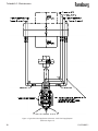
Turbodisk 2 - Maintenance
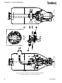
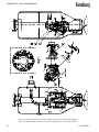
Figure 7: Typical No Valve Application Schematic - Dual Fluid Supply Option
(Reference Figure 12)
30
LN-9240-02.1
Turbodisk 2 - Maintenance
Figure 8: Typical 3-Way Valve Application Schematic - Dual Fluid Supply Option
(Reference Figure 13)
LN-9240-02.1
31
Turbodisk 2 - Maintenance
Figure 9: Typical Trigger and Dump Valve Application with (High Flow) Fluid Regulator Schematic - Dual Fluid Supply
Option (Reference Figure 14)
32
LN-9240-02.1
Turbodisk 2 - Maintenance
Figure 10: Typical Trigger and Dump Valve Application with DR-1 Fluid Regulator Schematic - Dual Fluid Supply with
Recirculating Option (Reference Figure 15)
LN-9240-02.1
33
Turbodisk 2 - Parts Identification
PARTS IDENTIFICATION
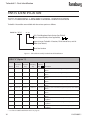
78715 TURBODISK 2 ASSEMBLY MODEL IDENTIFICATION
Turbodisk 2 Assemblies are available with the various options as follows:
Model No. 78715
-
xx xx
DR-1 Fluid Regulator Ratio Option (See Table B)
5
(Dash # required only when applicable) 4
Upper & Lower Turbodisk 2 Sections, Fluid Control Parts, and Air
Motor (See Table A)
Basic Part Number
Figure 11: Turbodisk 2 Assembly Standard Model Identification
TABLE "A" (Figure 11)
Dash #
Basic
Turbodisk 2
Assy
Turbine
Air Motor
Assy
Air Heater & Disk
Filter/Reg. Mounting
Nut 3
Assy
01
78718-01
78175-01
78781-00
19836-01
02
78718-02
78175-01
78781-00
19836-01
03
78718-03
78175-01
78781-00
19836-01
04
78718-04
78175-01
78781-00
19836-01
05
78718-01
78175-11
78781-00
19836-02
06
78718-02
78175-11
78781-00
19836-02
07
78718-03
78175-11
78781-00
19836-02
08
78718-04
78175-11
78781-00
19836-02
21
78718-11
78175-01
78781-00
19836-01
22
78718-12
78175-01
78781-00
19836-01
23
78718-13
78175-02
78781-00
19836-01
Description
No valves, Down Feed CW, Single Fluid System, 3/8 ID Tubing
Option
No valves, Down Feed CW, Single Fluid System, 1/4 ID Tubing
Option
No valves, Down Feed CW, Dual Fluid System, 3/8 ID Tubing
Option
No valves, Down Feed CW, Dual Fluid System, 1/4 ID Tubing
Option
No valves, Down Feed CCW, Single Fluid System, 3/8 ID Tubing
Option
No valves, Down Feed CCW, Single Fluid System, 1/4 ID Tubing
Option
No valves, Down Feed CCW, Dual Fluid System, 3/8 ID Tubing
Option
No valves, Down Feed CCW, Dual Fluid System, 1/4 ID Tubing
Option
3-Way On/Off, Down Feed CW, Single Fluid System, 3/8 ID Tubing Option
3-Way On/Off, Down Feed CW, Single Fluid System, 1/4 ID Tubing Option
3-Way On/Off, Down Feed CW, Dual Fluid System, 3/8 ID Tubing Option
* See "Parts List Bullet Definition Table" on page 37.
34
LN-9240-02.1
Turbodisk 2 - Parts Identification
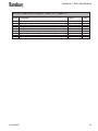
TABLE "A" (Figure 11) - (Continued)
Air Heater & Disk
Filter/Reg. Mounting
Nut 3
Assy
Dash #
Basic
Turbodisk 2
Assy
Turbine
Air Motor
Assy
24
78718-14
78175-02
78781-00
19836-01
25
78718-11
78175-11
78781-00
19836-02
26
78718-12
78175-11
78781-00
19836-02
27
78718-13
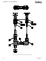
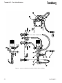
78175-12
78781-00
19836-02
28
78718-14
78175-12
78781-00
19836-02
1
41
78718-21
78175-02
78781-00
19836-01
1
42
78718-22
78175-02
78781-00
19836-01
1
43
78718-23
78175-02
78781-00
19836-01
1
44
78718-24
78175-02
78781-00
19836-01
1
45
78718-21
78175-12
78781-00
19836-02
1
46
78718-22
78175-12
78781-00
19836-02
1
47
78718-23
78175-12
78781-00
19836-02
1
48
78718-24
78175-12
78781-00
19836-02
61
78718-31
78175-02
78781-00
19836-01
62
78718-32
78175-02
78781-00
19836-01
63
78718-33
78175-02
78781-00
19836-01
64
78718-34
78175-02
78781-00
19836-01
65
78718-35
78175-02
78781-00
19836-01
66
78718-36
78175-02
78781-00
19836-01
67
78718-37
78175-02
78781-00
19836-01
2
2
2
2
2
2
2
Description
3-Way On/Off, Down Feed CW, Dual Fluid System, 1/4 ID Tubing Option
3-Way On/Off, Down Feed CCW, Single Fluid System, 3/8 ID
Tubing Option
3-Way On/Off, Down Feed CCW, Single Fluid System, 1/4 ID
Tubing Option
3-Way On/Off, Down Feed CCW, Dual Fluid System, 3/8 ID Tubing Option
3-Way On/Off, Down Feed CCW, Dual Fluid System, 1/4 ID Tubing Option
Trigger & Dump Valve w/Fluid Reg. (High Flow), Down Feed
CW, Single Fluid System, 3/8 ID Tubing Option
Trigger & Dump Valve w/Fluid Reg. (High Flow), Down Feed
CW, Single Fluid System, 1/4 ID Tubing Option
Trigger & Dump Valve w/Fluid Reg. (High Flow), Down Feed
CW, Dual Fluid System, 3/8 ID Tubing Option
Trigger & Dump Valve w/Fluid Reg. (High Flow), Down Feed
CW, Dual Fluid System, 1/4 ID Tubing Option
Trigger & Dump Valve w/Fluid Reg. (High Flow), Down Feed
CCW, Single Fluid System, 3/8 ID Tubing Option
Trigger & Dump Valve w/Fluid Reg. (High Flow), Down Feed
CCW, Single Fluid System, 1/4 ID Tubing Option
Trigger & Dump Valve w/Fluid Reg. (High Flow), Down Feed
CCW, Dual Fluid System, 3/8 ID Tubing Option
Trigger & Dump Valve w/Fluid Reg. (High Flow), Down Feed
CCW, Dual Fluid System, 1/4 ID Tubing Option
Trigger & Dump Valve w/DR-1 Fluid Reg. (Low Flow), Down
Feed CW, Single Fluid System, Non-Circulating Fluid Return,
3/8 ID Tubing Option
Trigger & Dump Valve w/DR-1 Fluid Reg. (Low Flow), Down
Feed CW, Single Fluid System, Non-Circulating Fluid Return,
1/4 ID Tubing Option
Trigger & Dump Valve w/DR-1 Fluid Reg. (Low Flow), Down
Feed CW, Dual Fluid System, Non-Circulating Fluid Return, 3/8
ID Tubing Option
Trigger & Dump Valve w/DR-1 Fluid Reg. (Low Flow), Down
Feed CW, Dual Fluid System, Non-Circulating Fluid Return, 1/4
ID Tubing Option
Trigger & Dump Valve w/DR-1 Fluid Reg. (Low Flow), Down
Feed CW, Single Fluid System, Recirculating Fluid Return, 3/8 ID
Tubing Option
Trigger & Dump Valve w/DR-1 Fluid Reg. (Low Flow), Down
Feed CW, Single Fluid System, Recirculating Fluid Return, 1/4 ID
Tubing Option
Trigger & Dump Valve w/DR-1 Fluid Reg. (Low Flow), Down
Feed CW, Dual Fluid System, Recirculating Fluid Return, 3/8 ID
Tubing Option
* See "Parts List Bullet Definition Table" on page 37.
LN-9240-02.1
35
Turbodisk 2 - Parts Identification
TABLE "A" (Figure 11) - (Continued)
2
2
2
2
2
Dash #
Basic
Turbodisk 2
Assy
Turbine
Air Motor
Assy
Air Heater &
Filter/Reg.
Assy
Disk
Mounting
Nut 3
68
78718-38
78175-02
78781-00
19836-01
69
78718-31
78175-12
78781-00
19836-02
70
78718-32
78175-12
78781-00
19836-02
71
78718-33
78175-12
78781-00
19836-02
72
78718-34
78175-12
78781-00
19836-02
73
78718-35
78175-12
78781-00
19836-02
74
78718-36
78175-12
78781-00
19836-02
75
78718-37
78175-12
78781-00
19836-02
76
78718-38
78175-12
78781-00
19836-02
2
2
2
2
Description
Trigger & Dump Valve w/DR-1 Fluid Reg. (Low Flow), Down
Feed CW, Dual Fluid System, Recirculating Fluid Return, 1/4 ID
Tubing Option
Trigger & Dump Valve w/DR-1 Fluid Reg. (Low Flow), Down
Feed CCW, Single Fluid System, Non-Circulating Fluid Return,
3/8 ID Tubing Option
Trigger & Dump Valve w/DR-1 Fluid Reg. (Low Flow), Down
Feed CCW, Single Fluid System, Non-Circulating Fluid Return,
1/4 ID Tubing Option
Trigger & Dump Valve w/DR-1 Fluid Reg. (Low Flow), Down
Feed CCW, Dual Fluid System, Non-Circulating Fluid Return, 3/8
ID Tubing Option
Trigger & Dump Valve w/DR-1 Fluid Reg. (Low Flow), Down
Feed CCW, Dual Fluid System, Non-Circulating Fluid Return, 1/4
ID Tubing Option
Trigger & Dump Valve w/DR-1 Fluid Reg. (Low Flow), Down
Feed CCW, Single Fluid System, Recirculating Fluid Return, 3/8
ID Tubing Option
Trigger & Dump Valve w/DR-1 Fluid Reg. (Low Flow), Down
Feed CCW, Single Fluid System, Recirculating Fluid Return, 1/4
ID Tubing Option
Trigger & Dump Valve w/DR-1 Fluid Reg. (Low Flow), Down
Feed CCW, Dual Fluid System, Recirculating Fluid Return, 3/8 ID
Tubing Option
Trigger & Dump Valve w/DR-1 Fluid Reg. (Low Flow), Down
Feed CCW, Dual Fluid System, Recirculating Fluid Return, 1/4 ID
Tubing Option
* See "Parts List Bullet Definition Table" on page 37.
36
LN-9240-02.1
Turbodisk 2 - Parts Identification
TABLE "B" (Figure 11)
Dash #
01
02
03
04
05
06
07
08
09
10
11
12
13
14
21
22
23
24
25
26
27
28
29
30
31
32
33
34
Description
Non-Circulating Fluid Return DR-1, Single Fluid System
Non-Circulating Fluid Return DR-1, Dual Fluid System
Non-Circulating Fluid Return DR-1, Single Fluid System
Non-Circulating Fluid Return DR-1, Dual Fluid System
Non-Circulating Fluid Return DR-1, Single Fluid System
Non-Circulating Fluid Return DR-1, Dual Fluid System
Non-Circulating Fluid Return DR-1, Single Fluid System
Non-Circulating Fluid Return DR-1, Dual Fluid System
Non-Circulating Fluid Return DR-1, Single Fluid System
Non-Circulating Fluid Return DR-1, Dual Fluid System
Non-Circulating Fluid Return DR-1, Single Fluid System
Non-Circulating Fluid Return DR-1, Dual Fluid System
Non-Circulating Fluid Return DR-1, Single Fluid System
Non-Circulating Fluid Return DR-1, Dual Fluid System
Recirculating Fluid Return DR-1, Single Fluid System
Recirculating Fluid Return DR-1, Dual Fluid System
Recirculating Fluid Return DR-1, Single Fluid System
Recirculating Fluid Return DR-1, Dual Fluid System
Recirculating Fluid Return DR-1, Single Fluid System
Recirculating Fluid Return DR-1, Dual Fluid System
Recirculating Fluid Return DR-1, Single Fluid System
Recirculating Fluid Return DR-1, Dual Fluid System
Recirculating Fluid Return DR-1, Single Fluid System
Recirculating Fluid Return DR-1, Dual Fluid System
Recirculating Fluid Return DR-1, Single Fluid System
Recirculating Fluid Return DR-1, Dual Fluid System
Recirculating Fluid Return DR-1, Single Fluid System
Recirculating Fluid Return DR-1, Dual Fluid System
Ratio Ref.
1:2
1:2
1:4
1:4
1:6
1:6
1:8
1:8
1:10
1:10
1:3
1:3
1:1
1:1
1:2
1:2
1:4
1:4
1:6
1:6
1:8
1:8
1:10
1:10
1:3
1:3
1:1
1:1
Regulator Assy
78719-01
78719-01 & -21
78719-02
78719-02 & -22
78719-03
78719-03 & -23
78719-04
78719-04 & -24
78719-05
78719-05 & -25
78719-06
78719-06 & -26
78719-11
78719-11 & -31
78719-41
78719-41 & -61
78719-42
78719-42 & -62
78719-43
78719-43 & -63
78719-44
78719-44 & -64
78719-45
78719-45 & 65
78719-46
78719-46 & -66
78719-51
78719-51 & -71
* PARTS LIST BULLET DEFINITION TABLE (Figure 11)
1
General Application Guideline: Use for fluid flow rates above 750 ml/min.
2
General Guideline: Use for fluid flow rates from 25 to 1500 ml/min.
Note: Assemblies using DR-1 fluid regulators (part number 74151-xx)
3
(1) Disk mounting nut (see Table "A") is included with this assembly. When installing disk (not included),
torque mounting nut to 50 - 60 lb•in. (Recommended: 3/8" hex bit socket with square drive torque wrench.)
4
DR-1 Non-circulating fluid return applies (see Table "B").
5
DR-1 Recirculating fluid return applies (see Table "B").
LN-9240-02.1
37
Turbodisk 2 - Parts Identification
Figure 12: 78718-04 Turbodisk 2 Assembly, No Valves,
Dual Fluid Supply System, 1/4 I.D. Tubing Option
38
LN-9240-02.1
Turbodisk 2 - Parts Identification
78718-04 TURBODISK 2 ASSEMBLY - PARTS LIST (Figure 12)
Item #
1
2
3
4
5
6
LN-9240-02.1
Description
Part #
Assembly, Basic Lower Turbodisk 2 Fluid Section
Assembly, Basic Upper Turbodisk 2 Bulkhead and Fairing
Fitting Package, Upper Turbodisk 2 Bulkhead, 1/4 I.D.
Fluid Supply Line Package, Lower Turbodisk 2 (No Valves)
Hook Assembly, Grounding (Not Shown)
Puller Assembly, Disk (Not Shown)
78733-02
78731-01
78729-04
78732-01
15946-00
19850-00
Qty
1
1
1
2
1
1
39
Turbodisk 2 - Parts Identification
Figure 13: 78718-14 Turbodisk 2 Assembly, 3-Way Valve (On/Off ),
Dual Fluid Supply System, 1/4 I.D. Tubing Option
40
LN-9240-02.1
Turbodisk 2 - Parts Identification
78718-14 TURBODISK 2 ASSEMBLY - PARTS LIST (Figure 13)
Item #
1
2
3
4
5
6
7
LN-9240-02.1
Description
Part #
Assembly, Basic Lower Turbodisk 2 Fluid Section
Assembly, Basic Upper Turbodisk 2 Bulkhead and Fairing
Fitting Package, Upper Turbodisk 2 Bulkhead, 1/4 I.D.
Assembly, 3-Way Valve w/Fluid Line Package, #1 Feed
Assembly, 3-Way Valve w/Fluid Line Package, #2 Feed
Hook Assembly, Grounding (Not Shown)
Puller Assembly, Disk (Not Shown)
78733-02
78731-01
78729-08
78723-01
78723-02
15946-00
19850-00
Qty
1
1
1
1
1
1
1
41
Turbodisk 2 - Parts Identification
Figure 14: 78718-24 Turbodisk 2 Assembly, Trigger & Dump Valve w/Fluid Regulator
(High Flow), Dual Fluid Supply System, 1/4 I.D. Tubing Option
42
LN-9240-02.1
Turbodisk 2 - Parts Identification
78718-24 TURBODISK 2 ASSEMBLY - PARTS LIST (Figure 14)
Item #
1
2
3
4
5
6
7
8
9
LN-9240-02.1
Description
Part #
Assembly, Basic Lower Turbodisk 2 Fluid Section
Assembly, Basic Upper Turbodisk 2 Bulkhead and Fairing
Fitting Package, Upper Turbodisk 2 Bulkhead, 1/4 I.D.
#1 Trigger and Dump Valve Assembly w/Fluid Line Package
#2 Trigger and Dump Valve Assembly w/Fluid Line Package
#1 Fluid Regulator Assembly, High Flow, w/Fluid Line Package
#2 Fluid Regulator Assembly, High Flow, w/Fluid Line Package
Hook Assembly, Grounding (Not Shown)
Puller Assembly, Disk (Not Shown)
78733-02
78731-01
78729-12
78722-01
78722-02
78714-03
78714-04
15946-00
19850-00
Qty
1
1
1
1
1
1
1
1
1
43
Turbodisk 2 - Parts Identification
Figure 15: 78718-38 Turbodisk 2 Assembly, Trigger & Dump Valve w/DR-1 Fluid Regulator
(Low Flow) Recirculating Fluid Return, Dual Fluid Supply System, 1/4 I.D. Tubing Option
44
LN-9240-02.1
Turbodisk 2 - Parts Identification
78718-38 TURBODISK 2 ASSEMBLY - PARTS LIST (Figure 15)
Item #
1
2
3
4
5
6
7
LN-9240-02.1
Description
Part #
Assembly, Basic Lower Turbodisk 2 Fluid Section
Assembly, Basic Upper Turbodisk 2 Bulkhead and Fairing
Fitting Package, Upper Turbodisk 2 Bulkhead, 1/4 I.D.
#1 Trigger and Dump Valve Assembly w/Fluid Line Package
#2 Trigger and Dump Valve Assembly w/Fluid Line Package
Hook Assembly, Grounding (Not Shown)
Puller Assembly, Disk (Not Shown)
78733-02
78731-01
78729-20
78722-01
78722-02
15946-00
19850-00
Qty
1
1
1
1
1
1
1
45
Turbodisk 2 - Parts Identification
Figure 16: 78733 Basic Lower Turbodisk 2 Fluid Control Assembly (Dual Feed)
46
LN-9240-02.1
Turbodisk 2 - Parts Identification
78733 LOWER TURBODISK 2 FLUID CONTROL ASSEMBLY - PARTS LIST (Figure 16)
Item #
1
2
3
4
5
6
7
8
9
10
11
12
13
14
15
16
17
18
19
20
LN-9240-02.1
Description
Part #
Qty
Bulkhead, Lower, Turbodisk 2 Quick Disconnect
Assembly, Latching, Bulkhead, Turbodisk 2 Fluid Section (Includes the Following): (Note: Qty is per each assembly)
Latch, Machined, Turbodisk 2 Fluid Section
Bracket, Machined, Latch Mounting
Sleeve, Machined, Turbodisk 2
Screw, Socket Head, 1/4 Shoulder x 1" Long, SST
Locknut, Hex Thin (Jam) Nylon-Insert, #10-32, SST
Spring, Torsion, Latch
Washer, Flat, #10, SST
Screw, Socket Head Cap, 1/4-20 x 3/8 Long
Washer, Lock, 1/4, Standard Helical Spring
Screw, Socket Head Cap, 3/8-24 x 1" Long
Washer, Lock, 3/8, Standard Helical Spring
Screw, Socket Head Cap, 5/16-24 x 1" Long
Washer, Lock, 5/16", Standard Helical Spring
Extension, Turbodisk 2 Assembly
Tube, Feed, Overhead Installation (Down Feed)
Transmitter, Fiber Optic, RPM
Assembly, Fiber Optic Cable
Screw, Set, #10-24 x 3/8 Long, SST w/Nylon Tip
O-Ring, Solvent Proof, .250 I.D. x .062 Cross Section
Stud, Air, Small
Stud, Air, Extra Large
O-Ring, Solvent Proof, .562 I.D. x .062 Cross Section
Fitting, Male Connector, 3/8" NPT, 1/2" O.D. Tube Size
Cap, Identification, Green, 1/2" O.D. Tube Size
Tubing, Nylon, Green, 1/2" O.D. x 3/8" I.D. x 13" Long
78700-00
78724-00
1
2
78706-00
78707-00
78708-00
78725-32F
78726-05
78728-00
78405-03
7959-12C
7734-06
8471-32F
7734-12
8532-32F
7734-07
78709-00
70976-01
SMC-29
78713-00
SSF-2052
SSG-8128
77507-00
78705-00
SSG-8165
78168-00
78169-00
78176-01
1
1
2
1
1
2
1
4
4
2
2
6
6
1
2
1
1
1
9
8
2
2
2
2
2
47
Turbodisk 2 - Parts Identification
Figure 17: 78731 Upper Turbodisk 2 Bulkhead Plate and Fairing Mounting
48
LN-9240-02.1
Turbodisk 2 - Parts Identification
78731 UPPER TURBODISK 2 BULKHEAD PLATE & FAIRING MOUNTING PARTS LIST (Figure 17)
Item #
1
2
3
4
5
6
7
8
9
10
LN-9240-02.1
Description
Part #
Plate, Bulkhead, Upper, Turbodisk 2
Screw, Socket Head Cap, 3/8-24 x 1" Long
Washer, Lock, 3/8, Standard Spring
Insulator
Screw, Retaining, Flange Mount, 3/8-16
Screw, Set, Hex Socket, #10-24 x 3/8 Long, SST
Fitting, High Voltage, Turbodisk 2 Bulkhead
Nut, Ferrule, Nylon, 5/8-20
Flange, Support, Turbodisk 2 Assembly (Includes the Following):
Flange, Support
Bulkhead
Clamp, Toe
Screw, 5/16-18 x 1-1/2 Long, Hex Head Cap
Washer, Lock, Spring, 5/16
Screw, 1/4-20 x 1-1/2 Long, Hex Head Cap
Washer, Lock, Spring, 1/4
Kit, Disposable Cover, Turbodisk 2 Fairing (Not Shown)
78699-00
8471-32F
7734-12
78710-00
78703-01
SSF-2052
78704-02
13521-03
70381-00
70380-00
70379-00
70378-00
8156-48C
7734-07
7958-48C
7734-06
78143-00
Qty
1
2
2
1
6
1
1
1
1
1
1
2
4
4
2
2
1
49
Turbodisk 2 - Parts Identification
Figure 18: 78732 Fluid Supply Line Package - Basic (No Valves)
50
LN-9240-02.1
Turbodisk 2 - Parts Identification
78732 FLUID SUPPLY LINE PACKAGE - PARTS LIST (Figure 18)
Item #
1
2
3
4
5
6
7
8
9
10
11
12
13
14
LN-9240-02.1
Description
Part #
Fitting, Fluid, Female, 3/8 O.D. Tube, Quick Disconnect
Nut, Hex, 11/16, 3/8 O.D. Tube, SST
Ferrule, Back, Tube, 3/8
Ferrule, Front, Tube, 3/8
Tubing, 3/8 O.D. x 1/4 I.D., (FEP) SSP-5020
Fitting, Male Connector, 3/8 O.D. Tube x 1/4 NPT, SST
Fitting, Street Tee, 1/4 NPT (M) x 1/4 NPT (F), SST
Valve, Check, 1/4 NPT (M) x 1/4 NPT (M)
Fitting, Elbow, 1/4 O.D. Tube x 1/4 NPT (F), SST
Tubing, 1/4 O.D. x .170 I.D., (FEP) Nut, Hex, 9/16, 1/4 O.D. Tube, SST
Ferrule, Back, Tube, 1/4
Ferrule, Front, Tube, 1/4
Fitting, Fluid, Female, 1/4 O.D. Tube, Quick Disconnect
78702-02
70591-03
70606-03
70607-03
7"
41-FTC-1002
LSFI0004-01
SSV-809
LSFI0006-01
76698-01
70591-01
70606-01
70607-01
78702-01
Qty
1
1
1
1
1
1
1
1
8"
1
1
1
1
51
Turbodisk 2 - Parts Identification
Figure 19: 78723-xx 3-Way Valve Assembly w/Fluid & Air Line Package
52
LN-9240-02.1
Turbodisk 2 - Parts Identification
78723-xx 3-WAY VALVE ASSY W/FLUID & AIR LINE PACKAGE PARTS LIST (Figure 19)
Item #
1
2
3
4
5
6
7
8
9
10
11
12
13
14
15
16
17
18
19
20
21
22
LN-9240-02.1
Description
Part #
Qty
Assembly, Fluid Valve, 3-Way, Rectangular Base
Fitting, Street Tee, 1/4 NPT (Male) x 1/4 NPT (Female), SST
Valve, Check, 1/4 NPT (Male) x 1/4 NPT (Male)
Fitting, Female Elbow, 1/4 O.D. Tube x 1/4 NPT, SST
Tubing, 1/4 O.D. x .170 I.D., (FEP) Fitting, Male Connector, 1/4 O.D. Tube x 1/4 NPT, SST
Tubing, 1/4 O.D. x .170 I.D., (FEP) Fitting, Male Elbow, 3/8 O.D. Tube x 1/8 NPT, SST
Fitting, Male Elbow, Swivel, 5/32 O.D. Tube x 1/8 NPT, Brass
Tubing, 5/32 O.D. x .106 I.D.:
Green Nylon (For 78723-01)
Natural Nylon (For 78723-02)
Cap, 5/32 O.D. Tube:
Green Identification (For 78723-01)
Natural Identification (For 78723-02)
Fitting, Male Connector, 5/32 O.D. Tube x 1/16 NPT
Tubing, 3/8 O.D. x 1/4 I.D., (FEP) Nut, Hex, 11/16, 3/8 O.D. Tube, SST
Ferrule, Back, Tube, 3/8
Ferrule, Front, Tube, 3/8
Fitting, Fluid, Female, 3/8 O.D. Tube, Quick Disconnect
Tubing, 3/8 O.D. x 1/4 I.D., (FEP) Nut, Hex, 9/16, 1/4 O.D. Tube, SST
Ferrule, Back, Tube, 1/4
Ferrule, Front, Tube, 1/4
Fitting, Fluid, Female, 1/4 O.D. Tube, Quick Disconnect
18283-02
LSFI0004-01
SSV-809
LSFI0006-01
76698-01
70590-01
76698-01
LSFI0007-06
41-FTP-1006
1
1
1
1
13"
2
11"
2
1
77536-03
77536-05
6.5"
6.5"
77545-03
77545-04
78716-01
SSP-5020
70591-03
70606-03
70607-03
78702-02
SSP-5020
70591-01
70606-01
70607-01
78702-01
2
2
1
10"
2
2
2
2
7"
1
1
1
1
53
Turbodisk 2 - Parts Identification
Figure 20: 78714-xx High Flow Fluid Regulator Assembly w/Fluid & Air Line Package
54
LN-9240-02.1
78714-xx HIGH FLOW FLUID REGULATOR ASSY W/FLUID
& AIR
PACKAGE
Turbodisk
2 LINE
- Parts
Identification
PARTS LIST (Figure 20)
78714-xx HIGH FLOW FLUID REGULATOR ASSY W/FLUID & AIR LINE PACKAGE PARTS LIST (Figure 20)
Item #
1
2
3
4
5
6
7
8
9
10
11
12
13
LN-9240-02.1
Description
Part #
Qty
Fluid Regulator Assembly, High Flow
Fitting, Male Elbow:
1/2 O.D. Tube x 1/2 NPT (For 78714-01 & -02)
3/8 O.D. Tube x 1/2 NPT (For 78714-03 & -04)
Fitting, Male Adapter:
1/2 NPT x 1/2 O.D. Stem (For 78714-01 & -02)
1/2 NPT x 3/8 O.D. Stem (For 78714-03 & -04)
Fitting, Swivel Male Elbow, 5/32 O.D. Tube x 1/4 NPT
Cap, 5/32 O.D. Tube:
Yellow Identification (For 78714-01 & -03)
Blue Identification (For 78714-02 & -04)
Fitting, Male Connector, 5/32 O.D. Tube x 1/16 NPT
Tubing, 5/32 O.D. x .106 I.D.:
Yellow Nylon (For 78714-01 & -03)
Blue Nylon (For 78714-02 & -04)
Fitting, Fluid, Female, Quick Disconnect:
1/2 O.D. Tube (For 78714-01 & -02)
3/8 O.D. Tube (For 78714-03 & -04)
Nut, Hex:
7/8, 1/2 O.D. Tube, SST (For 78714-01 & -02)
11/16, 3/8 O.D. Tube, SST (For 78714-03 & -04)
Ferrule, Back, Tube:
1/2 (For 78714-01 & -02)
3/8 (For 78714-03 & -04)
Ferrule, Front, Tube:
1/2 (For 78714-01 & -02)
3/8 (For 78714-03 & -04)
Tubing, (FEP) :
1/2 O.D. x 3/8 I.D. (For 78714-01 & -02)
3/8 O.D. x 1/4 I.D. (For 78714-03 & -04)
Fitting, Male Connector, 1/4 O.D. Tube x 1/4 NPT
70171-04
1
77767-04
77767-02
1
1
77768-03
77768-02
72070-10
1
1
1
77545-12
77545-01
78716-01
2
2
1
77536-07
77536-04
6"
6"
78702-03
78702-02
2
2
70591-05
70591-03
2
2
70606-05
70606-03
2
2
70607-05
70607-03
2
2
55994-26
SSP-5020
70590-01
7.5"
7.5"
1
55
Turbodisk 2 - Parts Identification
Figure 21: 78719-xx Fluid Regulator Assembly, Low Flow,
w/Fluid & Air Line Package (Non-Circulating Fluid Return)
56
LN-9240-02.1
Turbodisk 2 - Parts Identification
78719-xx FLUID REGULATOR ASSY, LOW FLOW, W/FLUID &
AIR LINE PACKAGE (Non-Circulating) - PARTS LIST (Figure 21)
Item #
1
2
3
4
5
6
7
8
9
10
11
12
13
14
15
16
Description
Part #
Qty
DR-1 Fluid Regulator Assembly, Low Flow, 2-Stage
Adapter, Swivel, 1/4 NPSF x 1/4 NPTM, SST
Fitting, Female Connector, 3/8 O.D. Tube x 1/4 NPT
Tube, Fluid Supply, 3/8" O.D. x .035 (Wall)
Fitting, Paint, 1/4" O.D. Tube x 1/8 NPSM
Fitting, Swivel Male Elbow, 5/32" O.D. Tube x 10-32 Thread
Cap, 5/32" O.D. Tube:
Yellow Identification (For 78719-01 thru -11)
Blue Identification (For 78719-21 thru -31)
Tubing, 5/32" O.D. x .106" I.D.:
Yellow Nylon (For 78719-01 thru -11)
Blue Nylon (For 78719-21 thru -31)
Cap, 5/32" O.D. Tube:
Orange Identification (For 78719-01 thru -11)
Gray Identification (For 78719-21 thru -31)
Tubing, 5/32" O.D. x .106" I.D.:
Orange Nylon (For 78719-01 thru -11)
Silver Nylon (For 78719-21 thru -31)
Fitting, Male Connector, 5/32 O.D. Tube x 1/16 NPT
Tubing, 1/4" O.D. x .156 I.D., (FEP) Nut, Hex, 11/16, 3/8 O.D. Tube, SST
Ferrule, Back, Tube, 3/8
Ferrule, Front, Tube, 3/8
Fitting, Fluid, Female, 3/8 O.D. Tube, Quick Disconnect
See Table "A"
101-9120
41-FTC-1005
78720-00
70589-05
72070-11
1
1
1
1
1
2
77545-12
77545-01
2
2
77536-07
77536-04
8.5"
8.5"
77545-13
77545-11
2
2
77536-08
77536-06
78716-01
55994-23
70591-03
70606-03
70607-03
78702-02
6.25"
6.25"
2
7"
1
1
1
1
TABLE "A" (Figure 21)
Assembly #
Regulator #
78719-01
78719-02
78719-03
78719-04
78719-05
78719-06
78719-11
78719-21
78719-22
78719-23
78719-24
78719-25
78719-26
78719-31
74151-01
74151-02
74151-03
74151-04
74151-05
74151-06
74151-11
74151-01
74151-02
74151-03
74151-04
74151-05
74151-06
74151-11
LN-9240-02.1
Regulator Ratio
1:2
1:4
1:6
1:8
1:10
1:3
1:1
1:2
1:4
1:6
1:8
1:10
1:3
1:1
57
Turbodisk 2 - Parts Identification
Figure 22: 78719-xx Fluid Regulator Assembly, Low Flow,
w/Fluid & Air Line Package (Recirculating Fluid Return)
58
LN-9240-02.1
Turbodisk 2 - Parts Identification
78719-xx FLUID REGULATOR ASSY, LOW FLOW, W/FLUID &
AIR LINE PACKAGE (Recirculating) - PARTS LIST (Figure 22)
Item #
1
2
3
4
5
6
7
8
9
10
11
12
13
14
15
16
17
Description
Part #
Qty
DR-1 Fluid Regulator Assembly, Low Flow, 2-Stage
Adapter, Swivel, 1/4 NPSF x 1/4 NPTM, SST
Fitting, Female Run Tee, 3/8 O.D. Tube x 1/4 NPT
Tube, Fluid Supply, 3/8" O.D. x .035 (Wall)
Fitting, Paint, 1/4" O.D. Tube x 1/8 NPSM
Fitting, Swivel Male Elbow, 5/32" O.D. Tube x 10-32 Thread
Cap, 5/32" O.D. Tube:
Yellow Identification (For 78719-41 thru -51)
Blue Identification (For 78719-61 thru -71)
Tubing, 5/32" O.D. x .106" I.D.:
Yellow Nylon (For 78719-41 thru -51)
Blue Nylon (For 78719-61 thru -71)
Cap, 5/32" O.D. Tube:
Orange Identification (For 78719-41 thru -51)
Gray Identification (For 78719-61 thru -71)
Tubing, 5/32" O.D. x .106" I.D.:
Orange Nylon (For 78719-41 thru -51)
Silver Nylon (For 78719-61 thru -71)
Fitting, Male Connector, 5/32 O.D. Tube x 1/16 NPT
Tubing, 3/8" O.D. x 1/4" I.D., (FEP) Nut, Hex, 11/16, 3/8 O.D. Tube, SST
Ferrule, Back, Tube, 3/8
Ferrule, Front, Tube, 3/8
Fitting, Fluid, Female, 3/8 O.D. Tube, Quick Disconnect
Tubing, 1/4" O.D. x .156 I.D., (FEP) See Table "A"
101-9120
78721-06
78720-00
70589-05
72070-11
1
1
1
1
1
2
77545-12
77545-01
2
2
77536-07
77536-04
8.5"
8.5"
77545-13
77545-11
2
2
77536-08
77536-06
78716-01
SSP-5020
70591-03
70606-03
70607-03
78702-02
55994-23
6.25"
6.25"
2
8"
2
2
2
2
7"
TABLE "A" (Figure 22)
Assembly #
Regulator #
78719-41
78719-42
78719-43
78719-44
78719-45
78719-46
78719-51
78719-61
78719-62
78719-63
78719-64
78719-65
78719-66
78719-71
74151-01
74151-02
74151-03
74151-04
74151-05
74151-06
74151-11
74151-01
74151-02
74151-03
74151-04
74151-05
74151-06
74151-11
LN-9240-02.1
Regulator Ratio
1:2
1:4
1:6
1:8
1:10
1:3
1:1
1:2
1:4
1:6
1:8
1:10
1:3
1:1
59
Turbodisk 2 - Parts Identification
Figure 23: 78781 Turbodisk 2 Air Heater and Filter/Regulator Assembly
60
LN-9240-02.1
Turbodisk 2 - Parts Identification
78781 TURBODISK 2 AIR HEATER & FILTER/REGULATOR ASSEMBLY - PARTS LIST
(Figure 23)
Item #
1
2
3
4
LN-9240-02.1
Description
Part #
Regulator Assembly, Turbodisk 2 Drive Air
Hose Assembly, Compressed Air
Air Heater Assembly
Tubing, 1/2" O.D. x .375" I.D., Green Nylon
78170-00
78166-00
20222-00
78176-01
Qty
1
1
1
(Ref )
61
Turbodisk 2 - Parts Identification
Figure 24: 78189 Turbodisk 2 Quick Release Fairing Assembly
62
LN-9240-02.1
Turbodisk 2 - Parts Identification
78189 TURBODISK 2 QUICK RELEASE FAIRING ASSEMBLY - PARTS LIST (Figure 24)
Item #
1
2
3
4
5
6
7
8
9
10
11
12
13
14
15
16
17
LN-9240-02.1
Description
Part #
Qty
Bulkhead, Machined, Turbodisk 2
Flange, Machined, Turbodisk 2 Support
Flange, Machined, Nylon Support
Screw, 1/4-20 x 3/4 Long, Nylon Hex Head
Screw, 5/16-24 x 1" Long, Hex Head
Lock Washer, 5/16 Helical Spring
Screw, 1/4-20 x 1/2" Long, Hex Head
Lock Washer, 1/4 Internal Tooth
Flat Washer, 1/4 Nylon
Nut, 1/4-20 Nylon Hex
Boot, Strain Relief
Plug, Machined, Feed Tube Adjustment
Shroud, Machined
Latch, Machined, Shroud
Screw, #6-32 x 1/2 Long, Nylon Flat Heat
Nut, #6-32 Nylon, Hex
Kit, Turbodisk 2 Shroud Disposable Cover (Not Shown)
78185-00
70147-00
70148-00
4322-24C
8156-32F
7734-07
7958-16C
7776-06
72471-01
72472-09
72128-00
70909-00
78186-00
78184-00
78188-00
8351-08
78143-00
1
1
1
6
2
2
6
6
4
4
1
2
1
4
16
16
1
63
Turbodisk 2 - Parts Identification
Figure 25: 78722-xx (2) Valve Assembly - Trigger & Dump
64
LN-9240-02.1
Turbodisk 2 - Parts Identification
78722-xx (2) VALVE ASSEMBLY - TRIGGER & DUMP PARTS LIST (Figure 25)
Item #
1
2
3
4
5
6
7
8
9
10
11
12
13
14
15
16
17
18
19
20
21
22
23
24
25
26
27
28
29
30
31
32
LN-9240-02.1
Description
Part #
Bracket, Fluid Valve Mounting
Fitting, Male Elbow, 1/2 O.D. Tube x 1/4 NPT, SST
Adapter, Turbodisk 2 Dump Valve
Fluid Valve Assembly
Pipe Nipple, 1/4-18 NPT x 7/8 Long
Fitting, Male Connector, 5/32 O.D. Tube x 1/8 NPT
Cap, 5/32 O.D. Tube:
Red Identification (For 78722-01)
Black Identification (For 78722-02)
Tubing, 5/32 O.D. x .106 I.D.:
Red Nylon (For 78722-01)
Black Nylon (For 78722-02)
Fitting, Male Connector, 5/32 O.D. Tube x 1/16 NPT
Cap, 5/32 O.D. Tube:
Green Identification (For 78722-01)
Natural Identification (For 78722-02)
Tubing, 5/32 O.D. x .106 I.D.:
Green Nylon (For 78722-01)
Natural Nylon (For 78722-02)
Tubing, 1/4 O.D. x .170 I.D., (FEP) Fitting, Female Elbow, 1/4 O.D. Tube x 1/4 NPT, SST
Valve, Check, 1/4 NPT (Male) x 1/4 NPT (Male)
Fitting, Male Branch Tee, 1/4 NPT
Fitting, Male Connector, 1/4 O.D. Tube x 1/4 NPT, SST
Tubing, 1/4 O.D. x .170 I.D., (FEP) Fitting, Reducing Adapter, 1/8 NPT(M) x 1/4 NPT(F), SST
Nut, Hex Jam, 5/8-18 UNF, SST
Adapter, Trigger Valve
Tubing, 1/2 O.D. x 3/8 I.D., (FEP) Fitting, Male Elbow, 1/4 O.D. Tube x 1/4 NPT, SST
Tubing, 1/4 O.D. x .170 I.D., (FEP) Nut, Hex, 7/8, 1/2 O.D. Tube, SST
Ferrule, Back, Tube, 1/2
Ferrule, Front, Tube, 1/2
Fitting, Fluid, Female, 1/2 O.D. Tube, Quick Disconnect
Fitting, Fluid, Female, 1/4 O.D. Tube, Quick Disconnect
Nut, Hex, 9/16, 1/4 O.D. Tube, SST
Ferrule, Back, Tube, 1/4
Ferrule, Front, Tube, 1/4
Tool, Valve (Not Shown)
78712-00
77767-03
78711-00
CCV-403-SS
SSP-440
41-FTP-1018
1
1
1
2
1
2
77545-05
77545-02
2
2
77536-02
77536-01
78716-01
9.5"
9.5"
2
77545-03
77545-04
2
2
77536-03
77536-05
76698-01
LSFI0006-01
SSV-809
76462-00
70590-01
76698-01
SSP-39
SSF-8125
CCV-12-SS
55994-26
LSFI0007-01
76698-01
70591-05
70606-05
70607-05
78702-03
78702-01
70591-01
70606-01
70607-01
CCV-7
Qty
9.5"
9.5"
7"
1
1
1
1
11.5"
1
1
1
7.5"
2
6.75"
1
1
1
1
1
1
1
1
1
65
Turbodisk 2 - Parts Identification
Figure 26: 78729 Upper Turbodisk 2 Bulkhead Plate Fitting Layout
(Reference Figures 3a & 3b)
66
LN-9240-02.1
Turbodisk 2 - Parts Identification
78729 UPPER TURBODISK 2 BULKHEAD PLATE FITTING PARTS LIST (Figure 26)
Item #
1
2
3
4
5
6
7
8
9
10
11
12
13
14
15
16
17
18
Description
Part #
P1D Fitting Subassembly
P1DL Fitting Subassembly
R1H Fitting Subassembly
R1L Fitting Subassembly
P1S Fitting Subassembly:
3/8 I.D.
1/4 I.D.
P1R Fitting Subassembly:
3/8 I.D.
1/4 I.D.
P1T Fitting Subassembly
P2D Fitting Subassembly
P2DL Fitting Subassembly
R2H Fitting Subassembly
R2L Fitting Subassembly
P2S Fitting Subassembly:
3/8 I.D.
1/4 I.D.
P2R Fitting Subassembly:
3/8 I.D.
1/4 I.D.
P2T Fitting Subassembly
S1.IN Fitting Subassembly
S2.IN Fitting Subassembly
T.A1 Fitting Subassembly
T.A2 Fitting Subassembly
78730-01
78730-02
78730-03
78730-04
Select Option
78730-05
78730-06
Select Option
78730-07
78730-08
78730-09
78730-10
78730-11
78730-12
78730-13
Select Option
78730-14
78730-15
Select Option
78730-16
78730-17
78730-18
78730-19
78730-20
78730-21
78730-22
Qty
1
1
1
1
1
1
1
1
1
1
1
1
1
1
1
1
1
1
1
1
1
1
Note: Reference Figure 3B for fitting identification designation.
LN-9240-02.1
67
Turbodisk 2 - Parts Identification
Figure 27: 78175-xx Turbodisk 2 Air Turbine Assembly
68
LN-9240-02.1
Turbodisk 2 - Parts Identification
78175-xx TURBODISK 2 AIR TURBINE ASSEMBLY PARTS LIST (Figure 27)
Item #
1
2
3
4
5
6
7
8
9
10
11
12
13
14
Description
Part #
Qty
Housing Assembly, Machined, Turbodisk 2 Upgrade
Screw, #8-32 x 5/16 Long, Slotted Round Head
Lock Washer, #8 Helical Spring
Plug, Protective
Muffler, 1" NPT Polyethylene Exhaust
Fitting, Machined, Exhaust Muffler Adapter
Identification Cap, 1/2" O.D. Tube, Green
Fitting, 1/2" NPT x 1/2" O.D. Tube
O-Ring, 4.239 I.D. x .070 c/s, Solvent Resistant
Screw, #8-32 x 3/8 Long, Socket Head Set
Air Motor Assembly, Turbodisk 2
Screw, #6-32 x 1/2 Long, Socket Head Cap
Nameplate, Turbodisk 2
Drive Screw
78174-00
7735-10C
7734-03
LS0135
78163-00
78173-00
78169-00
78168-00
7554-74
7716-12C
B*
10773-16C
70870-00
7612-43
1
8
8
1
1
A*
2
2
2
3
1
6
1
4
* See corresponding column in Table "A"
TABLE "A" (Figure 27)
Part #
78175-01
78175-02
78175-11
78175-12
Description
A
Air Motor Assembly, CW Rotation, w/o Exhaust Adapter
Air Motor Assembly, CW Rotation, w/Exhaust Adapter
Air Motor Assembly, CCW Rotation, w/o Exhaust Adapter
Air Motor Assembly, CCW Rotation, w/Exhaust Adapter
0
1
0
1
B
70879-406
70879-406
70879-456
70879-456
Notes**
1
1
**See "Parts List Bullet Definition Table"
** PARTS LIST BULLET DEFINITION TABLE (Figure 27)
1
The exhaust adapter is required only when the orientation of the fluid valving will not allow the exhaust muffler to be installed directly into the turbine housing. If the installed system provides an interference, then it
may be possible to re-orient the fluid valving so that the exhaust adapter is not required.
LN-9240-02.1
69
Turbodisk 2 - Parts Identification
Figure 28: 70879-xxx Turbodisk 2 Turbine Cartridge Assembly
70
LN-9240-02.1
Turbodisk 2 - Parts Identification
70879-xxx TURBODISK 2 TURBINE CARTRIDGE ASSEMBLY PARTS LIST (Figure 28)
Item #
1
2
3
4
5
6
7
8
9
10
11
12
13
14
15
16
17
18
Description
Part #
Qty
Retainer, Bearing
Screw, #6-32 x 3/8 Long, Hex Socket, Flat Head
Slinger
Spacer, Bearing
Bearing, Ball
O-Ring, 1.614 I.D., Solvent Resistant
O-Ring, 3.489 I.D., Solvent Resistant
Decal, 20292-xx Turbodisk
Key, Woodruff, 1/2 Dia.
Nut, Self-Lock, 5/8-18, UNF
Seat, Spring
Spring, Compression
Screw, Set, Special
Housing, Bearing, Machined
O-Ring, 2.239 I.D., Solvent Resistant
Plate, Nozzle
Rotor, Turbine
Shaft, Air Motor
70873-00
78232-12C
70876-00
20298-00
70896-00
7554-77
7554-73
73180-02
8310-01
7729-10
20966-00
70868-00
70871-00
70875-00
7554-17
A*
B*
C*
1
12
1
1
2
1
1
1
1
1
1
1
1
1
1
1
1
1
* See corresponding column in Table "A"
TABLE "A" (Figure 28)
Part #
70879-206
70879-256
70879-406
70879-456
LN-9240-02.1
Description
Motor, Turbodisk 2, CW Rotation
Motor, Turbodisk 2, CCW Rotation
Motor, Turbodisk 2, CW Rotation
Motor, Turbodisk 2, CCW Rotation
A
B
C
20291-06
20291-56
20291-10
20291-60
20292-31
20292-32
20292-31
20292-32
70897-01
70897-02
70897-01
70897-02
71
Turbodisk 2 - Warranty Policies
WARRANTY POLICIES
LIMITED WARRANTY
Ransburg will replace or repair without charge any
part and/or equipment that falls within the specified
time (see below) because of faulty workmanship or
material, provided that the equipment has been
used and maintained in accordance with Ransburg's
written safety and operating instructions, and has
been used under normal operating conditions.
Normal wear items are excluded.
FITNESS FOR A PARTICULAR PURPOSE. RANSBURG
ASSUMES NO LIABILITY FOR INJURY, DAMAGE TO
PROPERTY OR FOR CONSEQUENTIAL DAMAGES FOR
LOSS OF GOODWILL OR PRODUCTION OR INCOME,
WHICH RESULT FROM USE OR MISUSE OF THE
EQUIPMENT BY PURCHASER OR OTHERS.
THE USE OF OTHER THAN RANSBURG APPROVED
PARTS, VOID ALL WARRANTIES.
If, in Ransburg's opinion the warranty item in question,
or other items damaged by this part was improperly
installed, operated or maintained, Ransburg will
assume no responsibility for repair or replacement
of the item or items. The purchaser, therefore will
assume all responsibility for any cost of repair or
replacement and service related costs if applicable.
SPARE PARTS: One hundred and eighty (180) days
from date of purchase, except for rebuilt parts (any
part number ending in "R") for which the warranty
period is ninety (90) days.
EXCLUSIONS:
EQUIPMENT: When purchased as a complete unit,
(i.e., guns, power supplies, control units, etc.), is
one (1) year from date of purchase. WRAPPING THE
APPLICATOR, ASSOCIATED VALVES AND TUBING, AND
SUPPORTING HARDWARE IN PLASTIC, SHRINK-WRAP,
OR ANY OTHER NON-APPROVED COVERING, WILL
VOID THIS WARRANTY.
FLUID HANDLING: One (1) year from date of purchase
(i.e., Totalizer, CCV Valves, etc.).
AIR BEARING ROTATORS: Fifteen thousand (15,000)
hours or three (3) years, whichever occurs first.
Warranty period begins on the date of purchase.
RANSBURG'S ONLY OBLIGATION UNDER THIS
WARRANTY IS TO REPLACE PARTS THAT HAVE
FAILED BECAUSE OF FAULTY WORKMANSHIP OR
MATERIALS. THERE ARE NO IMPLIED WARRANTIES
NOR WARRANTIES OF EITHER MERCHANTABILITY OR
72
LN-9240-02.1
Turbodisk 2 - Appendix
APPENDIX
PAINT AND SOLVENT SPECIFICATIONS
REAtm / efmtm
RECOMMENDED VISCOSITY USING A ZAHN NO. 2
PAINT ELECTRICAL RESISTANCE**
RECOMMENDED DELIVERY (UP TO)
REMtm / m90TM
18 TO 30 SEC
.1 MΩ to ∞
1500 cc/min
18 TO 30 SEC
.1 MΩ to ∞
1000 cc/min
NO. 2 HAND GUN
TURBODISK tm
aerobell® ii***
aerobell®
Aerobell® 33 rma101TM
20 TO 60 SEC
.1 to 1 MΩ
180 cc/min
20 TO 60 SEC
.1 MΩ to ∞
1000 cc/min
20 TO 60 SEC
.1 MΩ to ∞
500 cc/min
GUIDE TO USABLE SOLVENT SELECTION
CHEMICAL
NAME
COMMON
NAME
CATEGORY
*CAS
NUMBER
DICHLOROMETHANE
METHYL ACETATE
VM & P NAPHTHA
ACETONE
BENZENE
ETHYL ACETATE
2-BUTANONE
iso-Propyl Acetate
ISOPROPYL ALCOHOL
2-PENTANONE
METHANOL
PROPYL ACETATE
TOLUOL
METHYL ISOBUTYL KETONE
ISOBUTYL ACETATE
ETHANOL
BUTYL ACETATE
ETHYLBENZENE
1-PROPANOL
2-BUTANOL
XYLOL
Amyl Acetate
2-METHYLPROPANOL
METHYL AMYL ACETATE
5-METHYL-2-HEXANONE
1-BUTANOL
2-ETHOXYETHANOL
2-HEPTANONE
CYCLOHEXANONE
AROMATIC-100
DIISOBUTYL KETONE
1-PENTANOL
DIACETONE ALCOHOL
2-BUTOXYETHANOL
CYCLOHEXANOL
AROMATIC-150
AROMATIC-200
Methylene Chloride
Chlorinated Solvents
Esters
Aliphatic Hydrocarbons
Ketones
Aromatic Hydrocarbons
Esters
Ketones
Esters
Alcohols
Ketones
Alcohols
Esters
Aromatic Hydrocarbons
Ketones
Esters
Alcohols
Esters
Aromatic Hydrocarbons
Alcohols
Alcohols
Aromatic Hydrocarbons
Esters
Alcohols
Esters
Ketones
Alcohols
Glycol Ethers
Ketones
Ketones
Aromatic Hydrocarbons
Ketones
Alcohols
Ketones
Glycol Ethers
Alcohols
Aromatic Hydrocarbons
Aromatic Hydrocarbons
75-09-2
79-20-9
803-232-4
67-64-1
71-43-2
141-78-6
78-93-3
108-21-4
67-63-0
107-87-9
67-56-1
109-60-4
108-88-3
108-10-1
110-19-0
64-17-5
123-86-4
100-41-4
71-23-8
78-92-2
133-02-07
628-63-7
78-83-1
108-84-9
110-12-3
71-36-3
110-80-5
110-43-0
108-94-1
Naptha
MEK
IPA
MPK
Methyl Alcohol
n-Propyl Acetate
Toluene
MIBK
Ethyl Alcohol
n-Propyl Alcohol
sec.-Butyl Alcohol
Xylene
iso-Butyl Alcohol
MIAK
n-Butyl Alcohol
MAK
SC#100
DIBK
Amyl Alcohol
Butyl Cellosolve
SC#150
* CAS Number: Chemical Abstract Service Number.
** Using the Ransburg Meter.
*** Solvent Base Configuration Only.
†
Information Obtained From: http://solvdb.ncms.org
Evaporation Rate is Based Upon Butyl Acetate Having a Rate of 1.0
108-83-8
71-41-0
123-42-2
111-76-2
108-93-0
EVAP.
RATE†
14.5
11.8
10
5.6
5.1
3.9
3.8
3.4
2.5
2.5
2.1
2.1
1.9
1.6
1.5
1.4
1.0
.89
.86
.81
.80
.67
.62
.50
.50
.43
.38
.40
.29
.20
.19
.15
.12
.07
.05
.004
.003
ELECTRICAL
RESISTANCE**
⇑F
HIGH
LOW
HIGH
LOW
HIGH
MEDIUM
MEDIUM
LOW
LOW
MEDIUM
LOW
LOW
HIGH
MEDIUM
LOW
LOW
LOW
HIGH
LOW
LOW
HIGH
MEDIUM
LOW
LOW
MEDIUM
LOW
LOW
MEDIUM
MEDIUM
HIGH
MEDIUM
LOW
LOW
LOW
LOW
HIGH
HIGH
A
S
T
E
R
S
L
O
W
E
R
⇓
©
2000, Ransburg
NOTE: This page provides resistivity determination and control information that we feel is necessary when using our electrostatic equipment. LN-9240-02.1
73
Turbodisk 2 - Appendix
Din Cup 4
Sears Craftsman
Cup
Saybolt Universal
SSU
Gardner Lithographic
Krebs Unit
KU
Gardner Holdt Bubble
Ford Cup 4
Ford Cup 3
30
16
10
80
34
17
11
Zahn 5
60
8 A-3
Zahn 4
5 A-4
25
Zahn 3
20
12
Zahn 2
11
30
Zahn 1
27
15
Fisher 2
Parlin 10
10
Fisher 1
Parlin 7
.1
.15
Poise
74
Centipoise
VISCOSITY CONVERSION CHART
.2
20
32
13
30
15
12
10
100
37
18
12
.25
25
37
14
35
17
15
12 A-2
130
41
19
13
.3
30
43
15
39
18
19
14 A-1
160
44
20
14
.4
40
50
16
50
21
25
18
.5
50
57
17
24
29
22
.6
60
64
18
29
33
25
.7
70
20
33
36
28
.8
80
22
39
41
31
.9
90
23
44
45
32
1.0
100
25
50
50
34
1.2
120
30
62
58
1.4
140
32
66
1.6
160
1.8
2.0
2.2
A
210
52
22
19
15
30
260
60
24
20
16
33
320
68
27
21
18
35
370
30
23
21
37
430
34
24
23
38
480
37
10
26
25
D
40
530
41
12
10
27
27
41
E
43
580
49
14
11
31
31
45
F
46
690
58
16
13
34
34
37
50
G
48
790
66
18
14
38
38
180
41
54
50
900
74
20
16
40
43
200
45
58
H
52
1000
82
23
17
10
44
46
220
62
I
54
1100
25
18
11
51
2.4
240
65
J
56
1200
27
20
12
55
2.6
260
68
58
1280
30
21
13
58
2.8
280
70
K
59
1380
32
22
14
63
3.0
300
74
L
60
1475
34
24
15
68
3.2
320
M
1530
36
25
16
72
3.4
340
N
1630
39
26
17
76
3.6
360
O
62
1730
41
28
18
82
3.8
380
1850
43
29
19
86
4.0
400
P
64
1950
46
30
20
90
4.2
420
2050
48
32
21
95
4.4
440
Q
2160
50
33
22
100
4.6
460
R
66
2270
52
34
23
104
4.8
480
67
2380
54
36
24
109
5.0
500
S
68
2480
57
37
25
112
5.5
550
T
69
2660
63
40
27
124
6.0
600
U
71
2900
68
44
30
135
7.0
700
74
3375
51
35
160
8.0
800
77
3380
58
40
172
9.0
900
V
81
4300
64
45
195
10.0 1000
W
85
4600
49
218
11.0 1100
88
5200
55
12.0 1200
92
5620
59
B
C
000
00
0
LN-9240-02.1
Turbodisk 2 - Appendix
21.0
2100
22.0
2200
23.0
2300
24.0
2400
25.0
2500
30.0
3000
35.0
3500
40.0
4000
45.0
4500
50.0
5000
23500
55.0
5500
26000
60.0
6000
65.0
6500
30000
70.0
7000
32500
75.0
7500
35000
80.0
8000
37000
85.0
8500
39500
90.0
9000
41000
95.0
9500
100.0 10000
64
8500
9000
103
9400
9850
10300
Z
2
105 10750
109 11200
Z-1
114 11600
121 14500
Z-2
3
129 16500
133 18500
Z-3
Z-4
136 21000
4
2800
43000
Z-5
5
46500
110.0 11000
51000
120.0 12000
55005
130.0 13000
60000
140.0 14000
65000
150.0 15000
Din Cup 4
2000
Sears Craftsman
Cup
20.0
Y
Zahn 5
1900
Zahn 4
1800
19.0
Zahn 3
18.0
1
Zahn 2
8000
X
Zahn 1
Saybolt Universal
SSU
101
Gardner Holdt Bubble
1700
Ford Cup 4
7500
17.0
16.0
Ford Cup 3
7000
100
15.0
Fisher 2
98
1600
1400
Fisher 1
1500
1300
14.0
Parlin 10
6480
13.0
Parlin 7
6100
96
Centipoise
95
Poise
Gardner Lithographic
Krebs Unit
KU
VISCOSITY CONVERSION CHART (Continued)
Z-6
67500
160.0 16000
74000
170.0 17000
83500
180.0 18000
83500
190.0 19000
88000
200.0 20000
93000
300.0 30000
140000
Note: All viscosity comparisons are as accurate as possible with existing information.
Comparisons are made with a material having a specific gravity of 1.0.
LN-9240-02.1
75
Turbodisk 2 - Appendix
VOLUMETRIC CONTENT OF HOSE OR TUBE
(English Units)
I.D. (in)
cc/ft.
Cross
Section
(in2)
1/8
2.4
.012
3/16
5.4
.028
1/4
9.7
.049
5/16
15.1
.077
3/8
21.7
.110
1/2
38.6
.196
Length
5ft. (60")
10ft. (120")
15ft. (180")
25ft. (300")
50ft. (600")
.003 gal.
.4 fl. oz.
.007 gal.
.9 fl. oz.
.013 gal.
1.6 fl. oz.
.020 gal.
2.5 fl. oz.
.029 gal.
3.7 fl. oz.
.051 gal.
6.5 fl. oz.
.006 gal.
.8 fl. oz.
.014 gal.
1.8 fl. oz.
.025 gal.
3.3 fl. oz.
.040 gal.
5.1 fl. oz.
.057 gal.
7.3 fl. oz.
.102 gal.
13.1 fl. oz.
.010 gal.
1.2 fl. oz.
.022 gal.
2.8 fl. oz.
.038 gal.
4.9 fl. oz.
.060 gal.
7.6 fl. oz.
.086 gal.
11.0 fl. oz.
.153 gal.
19.6 fl. oz.
.016 gal.
2.0 fl. oz.
.036 gal.
4.6 fl. oz.
.064 gal.
8.2 fl. oz.
.100 gal.
12.7 fl. oz.
.143 gal.
18.4 fl. oz.
.255 gal.
32.6 fl. oz.
.032 gal.
4.1 fl. oz.
.072 gal.
9.2 fl. oz.
.127 gal.
16.3 fl. oz.
.199 gal.
25.5 fl. oz.
.287 gal.
36.7 fl. oz.
.510 gal.
65.3 fl. oz.
VOLUMETRIC CONTENT OF HOSE OR TUBE
(Metric Units)
76
I.D. (mm)
cc/m
Cross
Section
(mm2)
3.6
10.2
10.2
15.3 cc
30.5 cc
45.8 cc
61.1 cc
76.3 cc
5.6
24.6
24.6
36.9 cc
73.9 cc
110.8 cc
147.8 cc
184.7 cc
6.8
36.3
36.3
54.5 cc
109.0 cc
163.4 cc
217.9 cc
272.4 cc
8.8
60.8
60.8
91.2 cc
182.5 cc
273.7 cc
364.9 cc
456.2 cc
Length
1.5m
3.0m
4.5m
6.0m
7.5m
LN-9240-02.1
NOTES:
LN-9240-02.1
Service Manual Price: $50.00 (U.S.)
Automotive Systems*
Automotive Finishing Group
48152 West Road
Wixom, Michigan 48393
Telephone: (248) 668-8900
Fax: (248) 668-2160
Order Desk: (877) 852-7797 Technical/Service Assistance: (800) 626-3565 Fax: (877) 852-7796
Fax: (877) 852-7796
Industrial Systems
Ransburg Electrostatic Systems
320 Phillips Avenue
Toledo, Ohio 43612-1493
Telephone: (419) 470-2000
Fax: (419) 470-2270
Website: www.ransburg.com
E-Mail: [email protected]
Order Desk: (800) 726-8097 Technical/Service Assistance: (800) 233-3366 Fax: (800) 359-2341
Fax: (419) 470-2071
© 2013 Ransburg. All rights reserved.
Trademarks indicated with ® are registered with the United States Patent and Trademark Office by Ransburg.
Patents issued and pending in the United States Patent and Trademark Office.
*Ransburg Industrial Systems is an ISO 9001 compliant company registered with Factory Mutual.
Models and specifications subject to change without notice.
Form LN-9240-02.1
Litho in U.S.A.
01/13