1
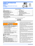
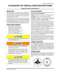
445349-CTG-B-0409
DESCRIPTION
TECHNICAL GUIDE
GAS-FIRED RESIDENTIAL
SINGLE STAGE MULTI-POSITION
GAS FURNACES
STANDARD &Low NOx MODELS
MODELS: TM8X / TMLX
NATURAL GAS
60 - 120 MBH INPUT
These compact units employ induced combustion, reliable hot
surface ignition and high heat transferaluminized tubular heat
exchangers. The units are factory shipped for installation in
upflow or horizontal applications and may be converted for
downflow applications.
These furnaces are designed for residential installation in a
basement, closet, alcove, attic, recreation room or garage and
are also ideal for commercial applications. All units are factory
assembled, wired and tested to assure safe dependable and
economical installation and operation.
These units are Category I listed and may be common vented
with another gas appliance as allowed by the National Fuel Gas
Code.
FEATURES
•
•
•
•
•
•
•
•
•
•
•
•
•
•
•
•
•
EFFICIENCY
RATING
CERTIFIED
ISO 9001
Certified Quality
Management System
Due to continuous product improvement, specifications
are subject to change without notice.
Visit us on the web at www.york.com
Additional rating information can be found at
www.ahridirectory.org
WARRANTY
•
•
•
•
•
•
•
•
•
•
20-year limited warranty on the heat exchanger.
10-year heat exchanger warranty on commercial applications.
Standard 5-year limited Parts warranty.
Extended 10-year limited parts warranty when product is registered online within 90 days of purchase for replacement or closing for new home construction.
Easily applied in upflow, horizontal left or right, or downflow
installation with minimal conversion necessary.
Compact, easy to install, ideal height 33" tall cabinet.
Blower-off delay for cooling SEER improvement.
Easy access to controls to connect power/control wiring.
Built-in, high level self diagnostics with fault code displays
standard on integrated control module for reliable operation.
Low unit amp requirement for easy replacement application.
All models are convertable to use propane (LP) gas.
Electronic Hot Surface Ignition saves fuel cost with increased
dependability and reliability.
100% shut off main gas valve for extra safety.
5 speed direct drive, X13 style high efficiency DC motor.
24V, 40 VA control transformer and blower relay supplied for
add-on cooling.
Hi-tech tubular aluminized steel primary heat exchanger.
Timed on, adjustable off blower capability for maximum
comfort.
Blower door safety switch.
Solid removable bottom panel allows easy conversion.
Low NOx models have been designed to meet specific code
requirements.
Airflow leakage less than 1% of total airflow at ductblaster
conditions.
No knockouts to deal with, making installation easier.
Movable duct connector flanges for application flexibility.
Quiet inducer operation.
Inducer rotates for easy conversion of venting options.
Fully supported blower assembly for easy access and
removal of blower.
External air filters used for maximum flexibility in meeting
customers IAQ needs.
Venting applications - may be installed as a common vent
with other gas-fired appliances or use a masonry chimney.
1/4 turn knobs provided for easy door removal.
High-efficiency blower motor for lower electrical power usage
and improved A/C SEER ratings.
Insulated blower compartment for thermal and acoustic
performance.
FOR DISTRIBUTION USE ONLY - NOT TO BE USED AT POINT OF RETAIL SALE
445349-CTG-B-0409
LEFT SIDE
Vent Connection
Outlet
FRONT
RIGHT SIDE
Electrical
Entry
Vent
Connection
Outlet
Electrical
Entry
Gas Pipe
Entry
33”
Gas Pipe
Entry
23”
Thermostat
Wiring
Thermostat
Wiring
14”
A
28.5”
29.5”
4” Diameter
Vent Connection
Outlet
24.38”
.5”
1”
1.5”
.5”
.5”
B
B
C
.5”
20”
24.25”
RETURN END
SUPPLY END
Cabinet and Duct Dimensions
Models
Nominal
3/min)
CFM (m
TM(8,L)X060A12MP11
TM(8,L)X080B12MP11
TM(8,L)X080C16MP11
TM(8,L)X100C16MP11
TM(8,L)X100C20MP11
TM(8,L)X120C20MP11
1200
1200
1600
1600
2000
2000
Cabinet
Size
A
B
C
C
C
C
Approximate
Operating Weights
Cabinet Dimensions (Inches)
A
B
C
Lbs
14 1/2
17 1/2
21
21
21
21
13 3/8
16 3/8
19 7/8
19 7/8
19 7/8
19 7/8
10.3
11.8
13.6
13.6
13.6
15.8
94
103
114
118
122
129
Ratings & Physical / Electrical Data
Models
TM(8,L)X060A12MP11
TM(8,L)X080B12MP11
TM(8,L)X080C16MP11
TM(8,L)X100C16MP11
TM(8,L)X100C20MP11
TM(8,L)X120C20MP11
Input
Output
MBH
60
80
80
100
100
120
MBH
48
64
64
80
80
96
AFUE
80.0
80.0
80.0
80.0
80.0
80.0
Air Temp. Max. Outlet
Rise
Air Temp
°F
°F
30-60
160
35-65
165
25-55
155
35-65
165
25-55
155
35-65
165
Max
Min. wire Size
Blower
Total Unit
Over-Current
(awg) @ 75 ft
Size
Amps
Protect
one way
Amps
6.8
11 x 8
15
9.3
14
6.8
11 x 8
15
9.3
14
6.8 11 x 10
15
9.3
14
6.8 11 x 10
15
9.3
14
8.4 11 x 11
15
10.9
14
8.4 11 x 11
15
10.9
14
Blower
HP
1/2
1/2
1/2
1/2
3/4
3/4
Nominal external static pressure is 0.50” w.c. at furnace outlet ahead of cooling coils.
Annual Fuel Utilization Efficiency (AFUE) numbers are determined in accordance with DOE Test procedures.
Wire size and over current protection must comply with the National Electrical Code (NFPA-70-latest edition) and all local codes.
HORIZONTAL SIDEWALL VENTING
For applications where vertical venting is not possible, the
only approved method of horizontal venting is the use of an
auxiliary power vent. Auxilary power venters must be
approved by CSA, UL, or other recognized safety agencies.
Follow all application and installation details provided by the
manufacturer of the power vent.
FILTER PERFORMANCE
All applications of these furnaces require the use of field
installed air filters. All filter media and mounting hardware or
provisions must be field installed external to the furnace cabinet. DO NOT attempt to install any filters inside the furnace.
NOTE: Single side return above 1800 CFM is approved as
long as the filter velocity does not exceed filter manufacturer’s recommendation and a transition is used to allow use
of a 20x25 filter.
The airflow capacity data published in the “Blower Performance” table listed above represents blower performance
WITHOUT filters.
2
Johnson Controls Unitary Products
445349-CTG-B-0409
Recommended Filter Sizes
Cabinet
Size
CFM
Side
(in)
Bottom
(in)
1200
A
16 x 25
14 x 25
1200
B
16 x 25
16 x 25
1600
C
16 x 25
20 x 25
2000
C
(2) 16 x 25
20 x 25
NOTES:
1. Air velocity through throwaway type filters may not exceed 300 feet per minute (91.4 m/min). All velocities over this require the use of high velocity filters.
2. Do not exceed 1800 CFM using a single side return and a 16x25 filter. For CFM greater than 1800, you may use two side returns or one side and the
bottom or one return with a transition to allow use of a 20x25 filter.
Unit Clearances to Combustibles (All dimensions in inches, and all surfaces identified with the unit in an upflow
configuration)
Application
Top
Front
Rear
Left
Side
Right
Side
Flue
Floor/
Bottom
Closet
Alcove
Attic
Line
Contact
Upflow
1
6
0
0
3
6
Combustible
Yes
Yes
Yes
No
Upflow B-Vent
1
3
0
0
0
1
Combustible
Yes
Yes
Yes
No
Downflow
1
6
0
0
3
6
11
Yes
Yes
Yes
No
Downflow B-Vent
1
3
0
0
0
1
11
Yes
Yes
Yes
No
Horizontal
1
6
0
0
3
6
Combustible
No
Yes
Yes
Yes2
Horizontal B-Vent
1
3
0
0
0
1
Combustible
No
Yes
Yes
Yes2
1. Special floor base or air conditioning coil required for use on combustible floor.
2. Line contact only permitted between lines formed by the intersection of the rear panel and side panel (top in horizontal position) of the furnace jacket and building joists, studs or framing.
ACCESSORIES
PROPANE (LP) CONVERSION KIT 1NP0347 - All Models
This accessory conversion kit may be used to convert natural
gas units for propane (LP) operation.
SIDE RETURN FILTER RACKS 1SR0200 - All Models
1SR0302 - All Models
BOTTOM RETURN FILTER RACKS 1BR0514 or 1BR0614 - For 14-1/2” cabinets
1BR0517 or 1BR0617 - For 17-1/2” cabinets
1BR0521 or 1BR0621 - For 21” cabinets
1BR05xx series are galvanized steel filter racks. 1BR06xx
are pre-painted steel filter racks to match the appearance of
the furnace cabinet.
COMBUSTIBLE FLOOR BASE KIT For installation of these furnaces in downflow applications
directly onto combustible flooring material. These kits are
required to prevent potential overheating situations. These
kits are also required in any applications where the furnace in
installed in a downflow configuration without an evaporator
coil, where the combustible floor base kit provides access for
combustible airflow.
1CB0514 - For 14-1/2” cabinets
1CB0517 - For 17-1/2” cabinets
1CB0521 - For 21” cabinets
Johnson Controls Unitary Products
EAC TRANSITION KITS For installation of EAC accessories with these furnaces to
provide easy transition of return airflow through the EAC to
get the proper sealing and reduced airflow leakage.
1TK1001 - For all models using side return
1TK1014 - For 14-1/2” cabinets using bottom return
1TK1017 - For 17-1/2” cabinets using bottom return
1TK1021 - For 21” cabinets using bottom return
MASONRY CHIMNEY KITS 1CK0603
1CK0604
For installations where these furnaces are vented using
existing or new lined masonry chimneys.
HIGH ALTITUDE PRESSURE SWITCHES For installation where the altitude is less than 5,000 feet it is
not required that the pressure switch be changed. For altitudes above 5,000 feet, see kits below.
1PS3301
1PS3302
ROOM THERMOSTATS - A wide selection of compatible
thermosets are available to provide optimum performance
and features for any installation.
1H/1C, manual change-over electronic non-programmable
thermostat.
1H/1C, auto/manual changeover, electronic programmable,
deluxe 7-day, thermostat.
1H/1C, auto/manual changeover, electronic programmable.
* For the most current accessory information, refer to the
price book or consult factory.
3
Blower Performance CFM - Any Position (without filter)
Airflow Data (SCFM)
Models
Speed
Ext. Static Pressure (in. H2O)
0.1
0.2
0.3
0.4
0.5
0.6
0.7
0.8
0.9
1.0
High
1350
1320
1280
1240
1200
1150
1100
1070
1020
970
Medium High
1180
1140
1100
1050
1010
970
920
860
810
780
Medium
1010
960
910
860
800
760
720
640
620
560
Medium Low
940
820
730
680
590
560
500
460
400
360
TM(8,L)X060A12MP11
Low
910
700
540
430
380
NA
NA
NA
NA
NA
High
1460
1440
1410
1240
1210
1170
1130
1090
1050
1000
Medium High
1190
1160
1130
1090
1050
1010
960
910
870
770
Medium
1010
970
940
890
840
800
750
700
610
570
Medium Low
980
860
770
730
660
620
490
460
400
360
TM(8,L)X080B12MP11
Low
910
800
590
430
400
NA
NA
NA
NA
NA
High
1780
1730
1690
1650
1590
1540
1490
1440
1400
1340
Medium High
1620
1570
1530
1480
1430
1390
1340
1280
1230
1100
Medium
1440
1400
1350
1290
1250
1200
1140
1090
1030
930
Medium Low
1250
1200
1140
1090
1030
970
910
850
720
680
TM(8,L)X080C16MP11
Low
1090
960
700
580
440
400
NA
NA
NA
NA
High
1750
1700
1660
1610
1560
1510
1460
1420
1370
1310
Medium High
1580
1540
1490
1440
1400
1350
1310
1260
1150
1110
Medium
1420
1380
1330
1290
1230
1180
1130
1080
990
910
Medium Low
1210
1170
1110
1060
1010
950
880
830
710
670
TM(8,L)X100C16MP11
Low
1020
890
660
560
420
390
NA
NA
NA
NA
High
2190
2160
2110
2060
2020
1980
1930
1890
1810
1710
Medium High
1830
1790
1740
1700
1650
1600
1520
1490
1430
1380
Medium
1580
1530
1480
1430
1380
1330
1280
1230
1160
1060
Medium Low
1410
1360
1310
1250
1190
1130
1070
1010
900
830
Low
1150
1020
850
770
680
560
510
NA
NA
NA
High
2210
2160
2120
2070
2030
1980
1950
1900
1840
1720
Medium High
1830
1800
1750
1710
1650
1610
1560
1520
1410
1350
Medium
1610
1560
1510
1470
1410
1360
1300
1250
1150
1060
Medium Low
1400
1340
1290
1230
1160
1100
1040
980
910
830
Low
1160
1020
850
770
680
620
510
NA
NA
NA
TM(8,L)X100C20MP11
TM(8,L)X120C20MP11
NOTES:
1. Airflow expressed in standard cubic feet per minute (CFM).
2. Motor voltage at 115 V.
Subject to change without notice. Printed in U.S.A.
Copyright © 2009 by Johnson Controls, Inc. All rights reserved.
Johnson Controls Unitary Products
5005 York Drive
Norman, OK 73069
445349-CTG-B-0409
Supersedes: 445349-CTG-A-0109