1
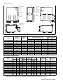
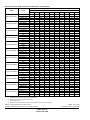
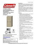
363657-YTG-C-0708
DESCRIPTION
TECHNICAL GUIDE
GAS-FIRED RESIDENTIAL
SINGLE STAGE MULTI-POSITION
GAS FURNACES
STANDARD & Low NOx MODELS
These compact units employ induced combustion, reliable
hot surface ignition and high heat transfer aluminized tubular
heat exchangers. The units are factory shipped for installation in upflow or horizontal applications and may be converted for downflow applications.
These furnaces are designed for residential installation in a
basement, closet, alcove, attic, recreation room or garage
and are also ideal for commercial applications. All units are
factory assembled, wired and tested to assure safe dependable and economical installation and operation.
These units are Category I listed and may be common vented
with another gas appliance as allowed by the National Fuel
Gas Code.
WARRANTY
20-year limited warranty on the heat exchanger.
10-year heat exchanger warranty on commercial applications.
5-year limited parts warranty.
MODELS: TG8S / TGLS
NATURAL GAS
40 - 130 MBH INPUT
FEATURES
•
•
•
•
•
•
•
•
•
•
•
•
EFFICIENCY
RATING
CERTIFIED
•
•
ISO 9001
Certified Quality
Management System
Due to continuous product improvement,
specifications are subject to change without notice.
Visit us on the web at www.york.com for the most
up-to-date technical information.
Additional efficiency rating information can
be found at www.gamanet.org.
•
•
•
•
•
•
•
•
•
•
•
•
Easily applied in upflow, horizontal left or right, or
downflow installation with minimal conversion necessary.
Compact, easy to install, ideal height 33" tall cabinet.
Blower-off delay for cooling SEER improvement.
Easy access to controls to connect power/control wiring.
Built-in, high level self diagnostics with fault code displays
standard on integrated control module for reliable
operation.
Low unit amp requirement for easy replacement
application.
Single wire twinning or staging feature available.
All models are convertable to use propane (LP) gas.
Electronic Hot Surface Ignition saves fuel cost with
increased dependability and reliability.
100% shut off main gas valve for extra safety.
4 speed, direct drive PSC motor.
24V, 40 VA control transformer and blower relay supplied
for add-on cooling.
Hi-tech tubular aluminized steel primary heat exchanger.
Timed on, adjustable off blower capability for maximum
comfort.
Blower door safety switch.
Solid removable bottom panel allows easy conversion.
Low NOx models have been designed to meet specific
code requirements.
Airflow leakage less than 1% of total airflow at ductblaster
conditions.
No knockouts to deal with, making installation easier.
Movable duct connector flanges for application flexibility.
Quiet inducer operation.
Inducer rotates for easy conversion of venting options.
Fully supported blower assembly for easy access and
removal of blower.
External air filters used for maximum flexibility in meeting
customers IAQ needs.
Venting applications - may be installed as a common vent
with other gas-fired appliances or use a masonry chimney.
1/4 turn knobs provided for easy door removal.
FOR DISTRIBUTION USE ONLY - NOT TO BE USED AT POINT OF RETAIL SALE
363657-YTG-C-0708
LEFT SIDE
Vent Connection
Outlet
FRONT
RIGHT SIDE
Electrical
Entry
Vent
Connection
Outlet
Electrical
Entry
Gas Pipe
Entry
33”
Gas Pipe
Entry
23”
Thermostat
Wiring
Thermostat
Wiring
14”
A
28.5”
29.5”
4” Diameter
Vent Connection
Outlet
24.38”
.5”
1”
1.5”
.5”
.5”
B
B
C
.5”
20”
24.25”
RETURN END
SUPPLY END
Cabinet and Duct Dimensions
Models
Nominal
CFM (m /min)
Cabinet
Size
800
1000
1200
1200
1600
2200
1200
1600
2000
1600
2000
2000
A
A
A
B
C
C
B
C
C
C
C
D
3
TG(8,L)S040A08MP11
TG(8,L)S060A10MP11
TG(8,L)S060A12MP11
TG(8,L)S080B12MP11
TG(8,L)S080C16MP11
TG(8,L)S080C22MP11
TG(8,L)S100B12MP11
TG(8,L)S100C16MP11
TG(8,L)S100C20MP11
TG(8,L)S120C16MP11
TG(8,L)S120C20MP11
TG(8,L)S130D20MP11
Approximate
Operating Weights
Cabinet Dimensions (Inches)
A
B
C
Lbs
14 1/2
14 1/2
14 1/2
17 1/2
21
21
17 1/2
21
21
21
21
24 1/2
13 3/8
13 3/8
13 3/8
16 3/8
19 7/8
19 7/8
16 3/8
19 7/8
19 7/8
19 7/8
19 7/8
23 3/8
10.3
10.3
10.3
11.8
13.6
13.6
11.8
13.6
13.6
15.8
15.8
17.5
89
91
94
103
114
119
108
118
122
123
129
135
Ratings & Physical / Electrical Data
Models
TG(8,L)S040A08MP11
TG(8,L)S060A10MP11
TG(8,L)S060A12MP11
TG(8,L)S080B12MP11
TG(8,L)S080C16MP11
TG(8,L)S080C22MP11
TG(8,L)S100B12MP11
TG(8,L)S100C16MP11
TG(8,L)S100C20MP11
TG(8,L)S120C16MP11
TG(8,L)S120C20MP11
TG(8,L)S130D20MP11
Input
Output
MBH
40
60
60
80
80
80
100
100
100
120
120
130
MBH
32
48
48
64
64
64
80
80
80
96
96
104
AFUE
80.0
80.0
80.0
80.0
80.0
80.0
80.0
80.0
80.0
80.0
80.0
80.0
Air Temp. Max. Outlet
Rise
Air Temp
°F
°F
25-55
155
25-55
155
30-60
160
35-65
165
25-55
155
25-55
155
40-70
170
35-65
165
25-55
155
40-70
170
30-60
160
35-65
165
Max
Min. wire Size
Blower
Total Unit
Over-Current
(awg) @ 75 ft
Size
Amps
Protect
one way
Amps
2.1
9x8
10
4.5
14
3.8
9x8
10
6.0
14
4.8
11 x 8
10
7.0
14
4.8
11 x 8
10
7.5
14
7.5 11 x 10
15
10.0
14
14.5 11 x 11
20
16.0
12
4.8
9x8
10
7.5
14
7.5 11 x 10
15
10.0
14
14.5 11 x 11
20
17.0
12
7.5 11 x 10
15
10.0
14
14.5 11 x 11
20
17.0
12
14.5 11 x 11
20
17.0
12
Blower
HP
1/5
1/3
1/3
1/3
1/2
1
1/3
1/2
1
1/2
1
1
Nominal external static pressure is 0.50” w.c. at furnace outlet ahead of cooling coils.
Annual Fuel Utilization Efficiency (AFUE) numbers are determined in accordance with DOE Test procedures.
Wire size and over current protection must comply with the National Electrical Code (NFPA-70-latest edition) and all local codes.
2
Johnson Controls Unitary Products
363657-YTG-C-0708
HORIZONTAL SIDEWALL VENTING
Recommended Filter Sizes
For applications where vertical venting is not possible, the
only approved method of horizontal venting is the use of an
auxiliary power vent. Auxilary power venters must be
approved by CSA, UL, or other recognized safety agencies.
Follow all application and installation details provided by the
manufacturer of the power vent.
FILTER PERFORMANCE
The airflow capacity data published in the “Blower Performance” table listed above represents blower performance
WITHOUT filters.
All applications of these furnaces require the use of field
installed air filters. All filter media and mounting hardware or
provisions must be field installed external to the furnace cabinet. DO NOT attempt to install any filters inside the furnace.
NOTE: Single side return above 1800 CFM is approved as
long as the filter velocity does not exceed filter manufacturer’s recommendation and a transition is used to allow use
on a 20x25 filter.
Cabinet
Size
CFM
Side
(in)
Bottom
(in)
800
A
16 x 25
14 x 25
1000
A
16 x 25
14 x 25
1200
A
16 x 25
14 x 25
1200
B
16 x 25
16 x 25
1600
B
16 x 25
16 x 25
1600
C
16 x 25
20 x 25
2000
C
(2) 16 x 25
20 x 25
2200
C
(2) 16 x 25
20 x 25
2000
D
(2) 16 x 25
22 x 25
NOTES:
1. Air velocity through throwaway type filters may not exceed 300
feet per minute (91.4 m/min). All velocities over this require the
use of high velocity filters.
2. Do not exceed 1800 CFM using a single side return and a 16x25
filter. For CFM greater than 1800, you may use two side returns or
one side and the bottom or one return with a transition to allow
use of a 20x25 filter.
Unit Clearances to Combustibles (All dimensions in inches, and all surfaces identified with the unit in an upflow
configuration)
Application
Top
Front
Rear
Left
Side
Right
Side
Flue
Floor/
Bottom
Closet
Alcove
Attic
Line
Contact
Upflow
1
6
0
0
3
6
Combustible
Yes
Yes
Yes
No
Upflow B-Vent
1
3
0
0
0
1
Combustible
Yes
Yes
Yes
No
Downflow
1
6
0
0
3
6
11
Yes
Yes
Yes
No
Downflow B-Vent
1
3
0
0
0
1
11
Yes
Yes
Yes
No
Horizontal
1
6
0
0
3
6
Combustible
No
Yes
Yes
Yes2
Horizontal B-Vent
1
3
0
0
0
1
Combustible
No
Yes
Yes
Yes2
1. Special floor base or air conditioning coil required for use on combustible floor.
2. Line contact only permitted between lines formed by the intersection of the rear panel and side panel (top in horizontal position) of the furnace jacket and building joists, studs or framing.
Johnson Controls Unitary Products
3
363657-YTG-C-0708
ACCESSORIES
PROPANE (LP) CONVERSION KIT 1NP0347 - All Models except 130,000 BTU input
1NP0501 - 130,000 BTU input only
This accessory conversion kit may be used to convert natural
gas units for propane (LP) operation.
SIDE RETURN FILTER RACKS 1SR0200 - All Models
1SR0302 - All Models
1SF0101 - All Models
BOTTOM RETURN FILTER RACKS 1BR0514 or 1BR0614 - For 14-1/2” cabinets
1BR0517 or 1BR0617 - For 17-1/2” cabinets
1BR0521 or 1BR0621 - For 21” cabinets
1BR0524 or 1BR0624 - For 24-1/2” cabinets
1BR05xx series are galvanized steel filter racks. 1BR06xx
are pre-painted steel filter racks to match the appearance of
the furnace cabinet.
COMBUSTIBLE FLOOR BASE KIT For installation of these furnaces in downflow applications
directly onto combustible flooring material, These kits are
required to prevent potential overheating situations. These
kits are also required in any applications where the furnace in
installed in a downflow configuration without an evaporator
coil, where the combustible floor base kit provides access for
combustible airflow.
1CB0514 - For 14-1/2” cabinets
1CB0517 - For 17-1/2” cabinets
1CB0521 - For 21” cabinets
1CB0524 - For 24-1/2” cabinets
4
EAC TRANSITION KITS For installation of EAC accessories with these furnaces to
provide easy transition of return airflow through the EAC to
get the proper sealing and reduced airflow leakage.
1TK1001 - For all models using side return
1TK1014 - For 14-1/2” cabinets using bottom return
1TK1017 - For 17-1/2” cabinets using bottom return
1TK1021 - For 21” cabinets using bottom return
1TK1024 - For 24-1/2” cabinets using bottom return
MASONRY CHIMNEY KITS 1CK0603
1CK0604
For installations where these furnaces are vented using
existing or new lined masonry chimneys.
HIGH ALTITUDE PRESSURE SWITCHES For installation where the altitude is less than 8,000 feet it is
not required that the pressure switch be changed. For altitudes above 8,000 feet, see kits below.
1PS3301
1PS3302
ROOM THERMOSTATS - A wide selection of compatible
thermosets are available to provide optimum performance
and features for any installation.
1H/1C, manual change-over electronic non-programmable
thermostat.
1H/1C, auto/manual changeover, electronic programmable,
deluxe 7-day, thermostat.
1H/1C, auto/manual changeover, electronic programmable.
* For the most current accessory information, refer to the
price book or consult factory.
Johnson Controls Unitary Products
363657-YTG-C-0708
Blower Performance CFM - Any Position (without filter) - Bottom Return
Bottom Airflow Data (SCFM)
Models
TG(8,L)S040A08MP11
TG(8,L)S060A10MP11
TG(8,L)S060A12MP11
TG(8,L)S080B12MP11
TG(8,L)S080C16MP11
TG(8,L)S080C22MP11
TG(8,L)S100B12MP11
TG(8,L)S100C16MP11
TG(8,L)S100C20MP11
TG(8,L)S120C16MP11
TG(8,L)S120C20MP11
TG(8,L)S130D20MP11
Speed
Ext. Static Pressure (in. H2O)
0.1
0.2
0.3
0.4
0.5
0.6
0.7
0.8
0.9
1.0
High
966
923
874
804
717
566
386
121
NA
NA
Medium High
813
782
743
687
605
464
280
118
NA
NA
Medium Low
745
706
667
619
545
413
205
NA
NA
NA
Low
684
655
614
565
489
342
171
NA
NA
NA
High
1292
1230
1160
1088
1004
891
760
476
129
129
Medium High
1203
1157
1105
1035
942
846
728
485
133
129
Medium Low
1043
1010
962
905
823
705
491
305
124
123
Low
869
845
811
772
708
579
438
178
145
125
High
1358
1341
1319
1303
1275
1238
1190
1130
1062
943
Medium High
1097
1083
1075
1064
1042
1024
997
962
906
821
Medium Low
935
928
920
899
872
840
809
771
731
659
Low
800
779
763
736
711
687
657
622
584
529
High
1329
1307
1285
1247
1195
1143
1091
1027
927
806
Medium High
994
1004
1008
984
970
941
893
839
773
669
Medium Low
786
790
782
781
761
743
726
685
630
540
Low
655
654
647
629
620
594
560
524
469
399
High
1881
1822
1783
1696
1602
1539
1465
1394
1267
1130
Medium High
1553
1535
1492
1456
1408
1343
1279
1226
1113
1014
Medium Low
1312
1286
1288
1260
1205
1143
1091
1029
966
841
Low
1169
1166
1128
1098
1069
1032
987
909
835
747
High
2811
2725
2638
2540
2448
2339
2224
2111
1974
1831
Medium High
2234
2233
2147
2092
2042
1974
1907
1820
1705
1575
Medium Low
1722
1716
1690
1681
1603
1553
1489
1426
1335
1241
Low
1396
1375
1348
1325
1263
1200
1150
1120
1052
965
High
1314
1318
1292
1265
1223
1177
1119
1051
971
890
Medium High
1010
1004
1003
995
992
956
914
857
798
721
Medium Low
812
805
796
786
777
754
727
685
626
560
Low
661
659
644
623
614
605
568
532
482
399
High
2069
2014
1956
1885
1820
1748
1668
1577
1468
1362
Medium High
1662
1656
1639
1608
1586
1544
1491
1421
1338
1204
Medium
1368
1371
1377
1376
1367
1334
1295
1250
1188
1104
Low
1016
1014
1018
1030
1012
996
975
944
898
852
High
2893
2774
2687
2589
2478
2376
2255
2120
1978
1824
Medium High
2272
2243
2204
2169
2086
2018
1940
1842
1743
1602
Medium Low
1765
1752
1737
1718
1674
1619
1561
1493
1437
1312
Low
1425
1380
1409
1378
1307
1274
1226
1180
1113
1025
High
1752
1724
1702
1664
1600
1542
1454
1372
1264
1119
Medium High
1469
1449
1453
1420
1382
1344
1269
1197
1118
1022
Medium Low
1248
1235
1226
1207
1179
1133
1077
992
922
841
Low
1076
1076
1046
1025
1002
968
927
869
784
707
High
2701
2620
2533
2429
2338
2227
2112
1993
1861
1706
Medium High
2125
2083
2046
1994
1955
1901
1857
1737
1621
1497
Medium Low
1664
1664
1647
1619
1580
1555
1468
1392
1332
1226
Low
1358
1339
1330
1318
1286
1235
1185
1141
1060
938
High
2823
2714
2613
2507
2399
2282
2170
2042
1908
1761
Medium High
2242
2188
2154
2102
2045
1970
1887
1792
1673
1537
Medium Low
1805
1791
1738
1725
1675
1623
1567
1487
1394
1256
Low
1425
1427
1403
1335
1324
1280
1236
1176
1103
996
NOTES:
1. Airflow expressed in standard cubic feet per minute (CFM).
2. Motor voltage at 115 V.
Johnson Controls Unitary Products
5
Blower Performance CFM - Any Position (without filter) - Left Side Return
Left Side Airflow Data (SCFM)
Models
TG(8,L)S040A08MP11
TG(8,L)S060A10MP11
TG(8,L)S060A12MP11
TG(8,L)S080B12MP11
TG(8,L)S080C16MP11
TG(8,L)S080C22MP11
TG(8,L)S100B12MP11
TG(8,L)S100C16MP11
TG(8,L)S100C20MP11
TG(8,L)S120C16MP11
TG(8,L)S120C20MP11
TG(8,L)S130D20MP11
Speed
High
Medium High
Medium Low
Low
High
Medium High
Medium Low
Low
High
Medium High
Medium Low
Low
High
Medium High
Medium Low
Low
High
Medium High
Medium
Low
High
Medium High
Medium Low
Low
High
Medium High
Medium Low
Low
High
Medium High
Medium Low
Low
High
Medium High
Medium Low
Low
High
Medium High
Medium
Low
High
Medium High
Medium Low
Low
High
Medium High
Medium Low
Low
Ext. Static Pressure (in. H2O)
0.1
0.2
0.3
0.4
0.5
0.6
0.7
0.8
0.9
1.0
994
824
757
707
1371
1249
1059
854
1406
1129
970
834
1274
975
777
647
1825
1516
1294
1126
2972
2173
1670
1371
1258
986
793
667
2009
1523
1230
1126
2964
2192
1699
1361
1789
1451
1202
1063
2828
2085
1620
1322
2958
2191
1737
1404
971
804
733
684
1323
1207
1026
836
1401
1126
947
809
1285
974
771
634
1781
1493
1297
1115
2863
2146
1667
1339
1278
995
786
653
1994
1506
1249
1115
2886
2178
1695
1356
1774
1445
1210
1050
2768
2073
1631
1311
2862
2182
1738
1394
942
777
694
641
1251
1158
997
809
1394
1107
933
797
1255
968
772
623
1746
1482
1271
1095
2769
2103
1647
1317
1283
1011
786
640
1933
1521
1245
1095
2794
2150
1706
1337
1738
1431
1266
1033
2699
2042
1636
1302
2758
2157
1713
1380
899
739
659
604
1169
1098
949
775
1379
1094
916
768
1239
960
762
610
1695
1464
1238
1049
2671
2082
1618
1284
1259
1003
783
629
1893
1490
1230
1049
2707
2109
1632
1304
1702
1413
1252
1010
2612
2029
1593
1271
2662
2092
1691
1355
829
675
575
495
1086
1018
889
717
1338
1076
890
740
1207
948
752
602
1641
1442
1187
1027
2571
2036
1585
1259
1240
962
780
604
1836
1466
1218
1027
2623
2098
1612
1267
1665
1394
1226
1007
2524
1967
1567
1241
2553
2085
1675
1327
725
489
444
397
971
921
793
576
1304
1047
863
710
1158
923
734
588
1587
1411
1120
996
2465
1966
1549
1199
1204
935
750
583
1763
1435
1195
996
2522
2007
1568
1243
1608
1362
1191
982
2423
1896
1557
1201
2447
1997
1590
1276
419
350
399
282
843
669
582
464
1261
1010
827
677
1111
879
695
552
1521
1343
1083
957
2352
1904
1492
1147
1149
913
733
558
1691
1393
1161
957
2415
1956
1519
1191
1514
1312
1082
941
2308
1893
1520
1162
2328
1932
1531
1220
120
361
NA
NA
521
503
420
216
1202
966
789
634
1049
823
651
506
1429
1275
1028
929
2227
1827
1408
1085
1073
861
702
519
1606
1326
1120
929
2281
1888
1460
1149
1431
1235
1028
889
2219
1816
1476
1101
2203
1844
1467
1163
NA
NA
NA
NA
NA
NA
NA
NA
1135
921
741
586
979
756
604
457
1330
1192
979
840
2095
1738
1350
1024
1015
808
627
469
1508
1241
1039
840
2149
1795
1392
1077
1343
1149
950
845
2118
1717
1407
1042
2056
1741
1389
1095
NA
NA
NA
NA
NA
NA
NA
NA
1040
843
668
534
830
672
529
381
1184
1035
851
742
1950
1621
1238
928
897
738
567
427
1389
1119
949
742
2012
1671
1293
994
1205
1037
852
778
1982
1635
1263
979
1893
1608
1276
1013
NOTES:
1.
2.
3.
4.
Airflow expressed in standard cubic feet per minute (CFM).
Return air is through side opposite motor (left side).
Motor voltage at 115 V.
Airflow through across motor side (right side) may be slightly less than the data shown above.
Subject to change without notice. Printed in U.S.A.
Copyright © 2008 by Johnson Controls, Inc. All rights reserved.
Johnson Controls Unitary Products
5005 York Drive
Norman, OK 73069
363657-YTG-C-0708
Supersedes: 363657-YTG-B-0608