Transcript
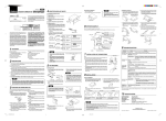
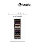
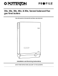
English 4 6 IDENTIFICATION OF PARTS This unit is available for upgrade in various ways. 1 Installation selector levers 3 2 Eject button DIGITAL AUDIO/12- DISC CD CHANGER Thank you for purchasing the CDC1255z/RDC1255z system. The CDC1255z/RDC1255z is designed incorporating the latest digital technologies, while featuring a newly developed CD mechanism to achieve excellent performance and good reliability. 3 Sliding door Please read this owner’s manual entirely before proceeding with installation. 5 Digital optical fiber output terminal CLASS 1 LASER PRODUCT Clarion Co.,Ltd. MADE IN JAPAN 051 722 877 CAUTION 2.Set the selectors on both side panels to the H Position when installing the set horizontally, to the V Position when installing the set vetically.When installing at the angle of 45, set the selectors to the center click position. The set may be damaged if the selectors are not set to the proper positions. ISO These limits are designed to provide reasonable protection against harmful interference in a residential installation. This equipment generates, uses, and can radiate radio frequency energy and, if not installed and used in accordance with the instructions, may cause harmful interference to radio communications. However, there is no guarantee that interference will not occur in a particular installation. If this equipment does cause harmful interference to radio or television reception, which can be determined by turning the equipment off and on, the user is encouraged to consult the dealer or an experienced radio/TV technician for help. GROUND THIS PRODUCTION COMPLIES WITH DHHS RULES 21 CFR SUBCHAPTER J APPLICABLE AT DATE OF MANUFACTURE. 8 Screws M5 8 W-SEMS CLARION CO.,LTD. 50 KAMITODA, TODA-SHI, SAITAMA-KEN, JAPAN. 45 V This equipment has been tested and found to comply with the limits for a Class B digital device, pursuant to Part 15 of the FCC Rules. 12V H 1.Be sure to use the screws, etc., included in the package tor installation.Using other screws could damage the set. MODEL THIS DEVICE COMPLIES WITH PART 15 OF THE FCC RULES. OPERATION IS SUBJECT TO THE FOLLOWING TWO CONDITIONS: (1) THIS DEVICE MAY NOT CAUSE HARMFUL INTERFERENCE, AND (2) THIS DEVICE MUST ACCEPT ANY INTERFERENCE RECEIVED, INCLUDING INTERFERENCE THAT MAY CAUSE UNDESIRED OPERATION. SERIAL No. USE OF CONTROLS, ADJUSTMENTS, OR PERFORMANCE OF PROCEDURES OTHER THAN THOSE SPECIFIED HEREIN, MAY RESULT IN HAZARDOUS RADIATION EXPOSURE. THE COMPACT DISC PLAYER SHOULD NOT BE ADJUSTED OR REPAIRED BY ANYONE EXCEPT PROPERLY QUALIFIED SERVICE PERSONNEL. CHANGES OR MODIFICATIONS NOT EXPRESSLY APPROVED BY THE MANUFACTURER FOR COMPLIANCE COULD VOID THE USER’S AUTHORITY TO OPERATE THE EQUIPMENT. INFORMATION FOR USERS:. CHANGES OR MODIFICATIONS TO THIS PRODUCT NOT APPROVED BY THE MANUFACTURER WILL VOID THE WARRANTY AND WILL VIOLATE FCC APPROVAL. 4 CeNET terminal for input and output (13-pin) ● CeNET with Balanced Audio Line Transmission and Dynamic Noise Canceling ● 120˚ Mounting Capability ● Dual 1-Bit D/A Converters ● Optical Digital Output ● Zero-Bit Detector Mute Circuit ● Dimensions: 10.6" (268mm)W × 3.9"(98mm)H × 6.7" (170mm)D ● 3-Beam Laser System 2 PRECAUTIONS 2. When playing 3" (8cm) CDs, use an adapter that conforms to the recommended CD standards or the adapter included with the mark. Refer to the adapter instruction manual concerning operation and loading 3" (8cm) CDs in the adapter. 3. ● The pickup, the heart of a player, is built in deep behind the door. Do not leave this door open for extended periods to prevent dust adhering to the pickup. 1. Rotate and change the switch using a fine-tipped screwdriver. 1 2. Rotate the switch until it clicks into position. CD changer 1 Address switch number 1 Important Important Be sure that the CD changer numbers are not the same. 2 CD changer Address switch number 2 CeNET wire bound CD changer 1 Address switch number 1 Source unit Important Do not use address switch numbers “3’ or “4’. • The unit may not operate when both CD changers are set to the same address switch number. • Never change the address switch during operation. Doing so can cause malfunction or breakdown. Do not change the address switch forcibly, because this may also cause malfunciton. 1. Load the discs with the labels facing upwards, as shown in the diagram. ● Always handle the compact disc by the edges. Never touch the surface. ● Do not use any solvents, such as commercially available cleaners, anti-static spray or thinner to clean compact discs. • When removing the digital optical fiber cable, rotate it to loosen it and pull it gently while holding the slide cap (a gray color part on the source unit). • Do not coil up the digital optical fiber cable with a radius of less than 1" (3 cm). With a radius of less than 1", the performance of the cable will be greatly impaired. • When installed in a glove box or console box, make sure that the source unit cables or cords do not interfere with the opening or closing of the slide door. Digtal optical fiber cable Slide cap 9 TROUBLESHOOTING 8 INSTALLATION Symptom ● Adjustment of Installation Selector Lever on the Right Side ●Adjustment of Installation Selector Lever at the base The installation direction can be adjusted by using the sharp end of a screwdriver or ballpen to insert into the round hole. The installation direction can be adjusted by inserting the sharp end of a small screwdriver into the square hole which can be seen from the adjustment hole. Insert correctly. A magazine is already Eject the magazine and insert the other. in the player. 1. Slide the sliding door to the right until it is completely latched on. “No Disc” sign appears when searching for discs. There is no CD in the After inserting a CD into the magazine, reload into the CD changer. magazine. Noise, skipping The installation selec- Set the installation selector levers to the same position on both sides. tor levers are set to different positions on both sides. H 45 V H V Label Side One in each slot (6 pieces) H: Horizontal 45: Slope ° 15 H V 45 H H V 3. After the magazine has been loaded, close the sliding door. Extracting the CD Extracting the Magazine Pull the disc lever in the direction of the arrow and a part of the disc will emerge from the magazine. Hold carefully the edge of the disc and pull it out. 1. Open the sliding door and depress the eject button. V: Vertical 30° 15° The unit installation direction and the installation selector lever positions do not match. Buy New Magazine CAA-122. Set the unit installation direction and the installation selector lever positions to match each other. When installed at an angle, change the installation selector lever to a position (H, 45, V) not prone to noise or sound loss. Disc bent or badly Compare with another disc. If bad, discard the damaged disc. damaged. • Use commercially sold adapters for 3” (8cm) CDs. • Some adapter may be transformed by heat. Magazine cannot Magazine inserted wrongly. be loaded. Distorted magazine. Sliding door • Up to two CD adapters can be used in one magazine. 3 or more adapters in a magazine may cause a trouble in ejection. Address switch num- When the 2 CD changers are connected, set the address switch so bers are the same. that they do not have the same address number. Refer to the “Example of address switch setting” in the section titled “IDENTIFICATION OF PARTS”. 2. Adjust the installation selector levers to the desired installation position. Inserting the Magazine Magazine Notes: Remedy Check connections. Connect the cable again. Loss of power Connection with the source unit is The length of the CeNET Rewire the connection so that the length of cable is less than 65.62 ft cable wiring is more than (20m). not recognized. 65.62 ft (20m). Prior to Installation ∗ Before shipment from the factory, the levers are normally placed in the horizontal position. Address switch ,,,,,,, ,,,,,,, ,,,,,,, ,,,,,,, ,,,,,,, Cause Bad connection. Right Side V 45 H H Set the position of the installation selector levers on the right side and at the base of the unit to “H”. Right Side 45 Disc is very dirty. Base Set the position of the installation selector levers on the right side and at the base of the unit to “45”. Right Side Clean the disc. H Mechanism does Mechanical error. not function. V V Base V 45 ● Never play a compact disc with any cellophane tape or other glue on it or with peeling off marks. If you try to play such a compact disc, you may not be able to get it back out of the CD player or it may damage the CD player. Cleaning ● To remove fingermarks and dust, use a soft cloth and wipe in a straight line from the center of the compact disc to the circumference. When the CeNET cable is connected, it must be inserted fully and securely. After connecting, fasten the cable using the cable holder or cable clamp. After connecting, fasten the cables with cable holders, etc. Disc Lever (White color) Base 1. Referring to section “INSTALLATION”, check the three angle of installation selector levers are properly set. If not, set them at the proper position for the angle of installation. 2. Check whether the CD magazine can be ejected by pressing the CD magazine eject button, then insert a new CD magazine. Set the position of the installation selector levers on the right side and at the base of the unit to “V”. lf the same phenomenon still occurs after checking the above, or it is impossible to remove the magazine, please consult your local dealer. Caution Pull • Adjust the installation selector levers into the correct locations. Setting the locations incorrectly or in varied positions will cause skipping. • Do not move the installation selector levers while the unit is in use. This will cause damage to the mechanism and the disc. Storage ● Do not expose compact discs to direct sunlight or any heat source. ● Do not expose compact discs to direct heat from heaters. • 7. Align the unit with the bolts and secure it with the wing nuts. 45 ● Do not use commercially available CD protection sheets or discs equipped with stabilizers, etc. These may get caught in the internal mechanism and damage the disc. CeNET cable Note: Only the provided screws and brackets should be used during installation. Using screws other than those specified will cause damage. 1. Decide on the installation place and direction. 2. Remove the magazine when it has been ejected. Installation Procedure ● Do not expose compact discs to excess humidity or dust. ● Never stick labels on the surface of the compact disc or mark the surface with a pencil or pen. 4 INSTALLATION OF CONNECTORS 45 mark. Use only compact discs bearing the Do not play heart-shaped, octagonal, or other specially shaped compact discs. Roughness 1 2 3 2. Load the magazine in the direction as shown in the diagram. Push it in until it is locked into the unit. CAUTIONS ON HANDLING CDs Ball-point pen Not used. (Suspending Position) 2. When the discs are loaded into the magazine the disc lever will move upwards in the direction of the arrow. Caution Handling ● New discs may have some roughness around the edge. The set may not work or the sound may skip if such discs are used. Use a ball-point pen, etc., to remove roughness from the edge of the disc. • Do not use address switch numbers “3” or “4”. 5 CD MAGAZINE Inserting the CD 7 Address switch number 1 Caution 6. Return the floor carpet to its original place. Use a knife to cut into the carpet where the bolt can be felt, and allow the bolt to protrude from the carpet. Digital optical fiber cable Address switch Source unit 5. Do not expose the magazine to direct sunlight, the car heater or other sources of strong heat. Replace the CD magazine (CAA-122) with a new one if bent or otherwise damaged. 3 4 <Example of address switch setting> 4. While the system is in play, do not plug or unplug the cables as this will cause damage. • ONLY use the magazine included with the CDC1255z or RDC1255z. For additional magazines, purchase Clarion Model CAA122. Do not attempt to insert different style magazine into the CD changer even if they fit into the magazine opening. Inserting other manufacturers’ magazines or previous Clarion 6 Pack style magazines into the CDC1255z or RDC1255z will cause damage to the mechanism and void the warranty. (Horizontal Position) CDC1255z/RDC1255z 45 ● When the inside of the car is very cold and the player is used soon after switching on the heater, dew may form on the disc or optical parts of the player and proper playback may not be possible. If dew forms on the disc, wipe it with a soft cloth. If dew forms on the optical parts of the player do not use the player for about one hour and the condensation will disappear naturally to allow normal operation. 4. Remove the separator of the cushion rubber that is attached to the installation bracket with bolt and install accordingly. 5. Unfasten the wing nut and remove the unit. 2 3 • The CeNET cable wiring must be less than 65.62 ft (20m) in length. 1. This unit does not operate independently. The unit must be used with a source unit that has a cable connection for CeNET wire bound (sold separately). Ferrite clamp (Brack) <How to change the address switch> ● Spring-Loaded Silicon Oil-Dampened Suspension System ● 8-Times Oversampling Digital Filter (Gray) (Gray) 1 ● Eject Capability While lgnition-Off (Brack) Y-adapter MD changer ● 12-Disc Capability (Two 6-Pack Magazines) (Vertical Position) MD changer When connecting an CD changer and MD changer by CeNET, no more than 2 units can be connected. When both of them are CD, the address switch needs to be reset so that the address switch number is not the same for each. ● Setting example 2 ,,, ,,, ,,, , ∗ The installation bracket with bolt may be broken off if it is bent many times at the perforated line. CeNET cable DPH7500z CeNET wire bound 1 FEATURES RCA extension cable 1 6 5 4 6 Address switch ● Setting example 1 3. Remove the floor carpet and decide on the place to install. Adjust the installation bracket with bolts to suit the place of installation. Source unit 15 ° 8-TIMES OVERSAMPLING DIGITAL FILTER /DUAL 1-BIT DAC OPTICAL DIGITAL OUTPUT When you want to upgrade the system, make sure that the upgrade unit fits and wire it correctly. 2 Press the eject button for ejecting the magazine. CDC1255z 2. Use the wing nut to hold in place the installation bracket with bolt to the installation bracket, which is attached to the unit. Then affix the cushion rubber. SYSTEM EXAMPLE 45° 12 DISC CD CHANGER Owner’s manual 15° 30° 280-7254-00 1. Use the double seamed hexagonal bolts to fix the lead clamp and installation bracket to the unit (on both sides) in the desired direction fo installation. Note: When taking out the CD do not let your fingers touch the signal side of the CD. Example 3. Close the sliding door. For your convinience, identification marks are put beside holes on the unit and the brackets. That is, holes with the “RH/LH” marks are to be used for horizontal, “RV/LV” for vertical installation and “RT/ LT” for suspending installation. ∗ For horizontal or suspending installation, use the attached installation screw to fix the lead clamp. 10 SPECIFICATONS Frequency Response Signal-to-Noise Ratio Wow and Flutter Power Supply Current Consumption Unit Weight Dimensions : 5Hz~20kHz(±1dB) : 105dB(1kHz)IHF•A : Below measurement limits : DC14.4V (10.8~15.6V) negative ground : Less than 1A : 7.28lb. (3.3kg) : 10.6"(Width) × 3.9" (Height) × 6.7"(Depth) [268mm(W) × 98mm(H) × 170(D)mm] ∗Due to improvements, the design and these specifications may be modified without prior notice. (Vertical Position) ● After using special compact disc cleaner, let the compact disc dry off well before playing it. Clarion Co.,Ltd. All right Reserved. Copyright © 1998:Clarion Co., Ltd. Printed in Japan 1998/10 (To.K) PE-2289 / 2287B 280-7254-00