1
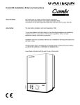
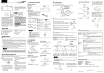
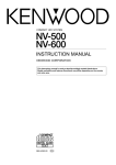
30e, 40e, 50e, 60e, & 80e, fanned balanced flue
gas fired boilers
THIS APPLIANCE IS FOR USE WITH NATURAL GAS (G20) ONLY
Installation and Servicing Instructions
LEAVE THESE INSTRUCTIONS ADJACENT TO THE GAS METER.
GAD (90/396/EEC)
POTTERTON PROFILE 30e G.C. No. 41 .605.39
POTTERTON PROFILE 40e G.C. No. 41 .605.40
POTTERTON PROFILE 50e G.C. No. 41 .605.41
POTTERTON PROFILE 60e G.C. No. 41 .605.42
POTTERTON PROFILE 80e G.C. No. 41 .605.43
IMPORTANT This appliance must be installed and serviced by a competent person as stated in the Gas Safety (Installation
and Use) Regulations 1994.
Profile boilers are certified for safety, it is therefore important that no external control devices (e.g. flue dampers,
economisers, etc.) be directly connected to these appliances unless covered by these installation instructions or otherwise
recommended in writing. Any direct connection of a control device not approved by Potterton could invalidate the certificate
and the normal warranty.
LIST OF CONTENTS - Page 2
General
Optional Extras
Accessories
Installation Data
Boiler Dimensions
Page No. 2
Page No. 2
Page No. 3
Page No. 3
Page No. 3
Site Requirements
Technical Data
Installation Instructions
Commissioning
Health and Safety Information
Control Systems, Pipework and
Wiring Guide
User’s Instructions
Page No. 3
Page No. 6
Page No. 11
Page No. 18
Back Page
Supplied in
Literature Pack
GENERAL - Page 2
Potterton Profile boilers are fully automatically controlled
wall mounted fan powered balanced flue appliances, using
a cast iron heat exchanger and are available in five outputs
ranging from 5.86-23.44kW (20,000-80,000 Btu/h).
The boilers which are designed to provide domestic hot
water and/or central heating must be used on INDIRECT
hot water systems only. The cast iron heat exchangers are
suitable for use on open vented gravity domestic hot
water/pumped central heating systems or fully pumped
systems which may be sealed or open vented.
All boilers can be supplied with either of the following types
of flue system:
1) Standard horizontal flue system suitable for wall
thickness of 100mm (4 in.) to 510mm (20 in.).
2) 2 metre horizontal flue system which provides a
maximum flue length Of 1955mm (77 in.).
3) Vertical flue system which allows the flue to pass
through a flat roof and terminate at a maximum height
of 1980mm (78 in.) measured from the top of the boiler
case.
OPTIONAL EXTRAS - Page 2
The following are kits available as optional extras:—
Internal Fitment Kit, which is suitable for a maximum wall
thickness of 51 0mm (20 in.) is to be used where access to
the outside wall is impracticable.
Pump Cover Kits, located on top of the boiler and
designed to conceal the pump, and/or any motorised valves
installed above the boiler. (Note: Pump cannot be fitted
above the boiler if the vertical flue kit is used).
Terminal Wall Plate, where necessary can be fitted to the
outside wall face to improve the appearance, after making
good around the terminal.
Terminal Guard, to be used when the terminal is fitted less
than 2m above a balcony, above ground or above a flat roof
to which people have access.
Full fitting instructions are provided with each kit.
P.I.L. PART Nos.
ACCESSORIES - Page 3
The following Potterton Myson controls are recommended
for use with your boiler:Electronic Programmer EP2001, EP3001, or EP6000
Cylinder Thermostat PTT2 or PTT1 00
Room Thermostat PRT2 or PRT1 00
Frost Thermostat PRT1 00 FR
Motorised Zone Valve M5V222 or M5V228
Motorised Diverter Valve M5V322
Thermostatic Radiator Valve
Data sheets describing these products are available on
request.
INSTALLATION DATA - Page 3
The installation of the boiler must be in accordance with the
latest relevant requirements of the Gas Safety (Installation
and Use) Regulations, local building regulations, lEE Wiring
Regulations and the Byelaws of the Local Water
Undertaking.
Detailed recommendations are contained in the following
British Standards and Codes of Practice.
B55440 Part 2 B55449 Part 1
B55546 B5481 4. B56891.
BUILDING REGULATIONS.
MODEL WATER BYELAWS.
BRITISH GAS PUBLICATION DM2.
GAS SAFETY (INSTALLATION AND USE)
REGULATIONS.
BUILDING STANDARDS (SCOTLAND)
REGULATIONS.
BS6798, B55440 Part 1
BOILER DIMENSIONS - Page 3
R.c ½
*NOTE:
IF PIPEWORK IS TO BE RUN DOWN THE BACK OF THE BOILER
THE NORMAL CLEARANCE OF 25mm BETWEEN THE REAR OF
THE BOILER AND WALL CAN BE INCREASED TO 35mm IF
DESIRED BY INVERTING THE BOILER MOUNTING PLATE DURING
INSTALLATION
(Dimensions in brackets apply when the mounting plate is inverted).
SITE REQUIREMENTS - Page 3
These boilers are not suitable for external installation and
should not be fitted directly above a cooking appliance. The
boiler may be installed in any room, although particular
attention is drawn to the requirements of the current I.E.E.
Wiring Regulations and in Scotland, the electrical provisions
of the Building Standards applicable in Scotland with
respect to the
installation of the appliance in a room containing a bath or
shower.
Where a room-sealed appliance is installed in a room
containing a bath or shower, any electrical switch or
appliance control, utilising mains electricity should be so
situated that it cannot be touched by a person using the
bath or shower.
SITE REQUIREMENTS - Page 4
FIG. 2 GENERAL ARRANGEMENT
SITE REQUIREMENTS - Page 5
Where the installation of the boiler will be in an unusual
location, special procedures may be necessary and BS 6798
gives detailed guidance on this aspect.
50mm (2 in) at the top (measured from the top of the boiler
case), except where the optional extra pump cover is to be
fitted, when 178mm (7 in) should be allowed.
Ensure that the gas supply pipe and meter are large enough
for this appliance and any others that may be run off the
same meter. Reference should be made to B56891
100mm (4 in) at the bottom of the boiler.
Boiler Mounting Surface
The boiler must be mounted on a flat wall, which may be of
combustible material and must be sufficiently robust to take
the weight of the boiler. The requirements of the local
authorities and the Building Regulations must be adhered to.
IMPORTANT NOTICE:
TIMBER FRAMED HOUSES
Additional clearances to these are required during
installation for lifting the boiler and 127mm (5 in) is required
at the top of the boiler for access to the pipe connections.
Ventilation
If the boiler is to be installed in a confined space such as a
cupboard, the space will need ventilating. Openings must be
provided at the top and bottom of the Cupboard each of
which should have a free area as shown in TABLE 1. Further
details for installation of a boiler within a compartment are
given in BS 6798.
If the appliance is to be fitted in a timber framed building, it
should be fitted in accordance with British Gas Publication
‘Operational Procedures for Customer Service’ Part 19. If in
any doubt, advice should be sought from the local region of
British Gas.
TABLE 1
AIR VENT AREAS
PROFILE
30e
40e
50e
60e
80e
Clearances Around the Boiler
The following minimum clearances must be maintained after
installation, for correct operation and servicing of the boiler:
in2
16
21
26
32
43
cm2
103
135
170
206
277
610mm (2 ft) at the front of the boiler
5mm (0.2 in) each side of the boiler
If the openings draw air from outside the building the free
areas may be halved. Refer to BS 5440 Part 2 for further
guidance.
Balanced Flue Terminal and Ducting
The fresh air inlet and flue ducts can be run from either the
left, right, rear or top of the boiler to a miniature terminal on
the outside of the building.
INFORMATION RELATING TO VERTICAL FLUING IS
PROVIDED IN THE PACK CONTAINING THE VERTI-CAL
FLUE SYSTEM.
The minimum spacings from the terminal to obstructions and
ventilation openings are shown in FIG. 3. For information
appertaining to horizontal flue lengths reference should be
made to FIG. 4.
NOTE
Where a flue terminal is fitted less than 1000mm from a
plastic or painted gutter or 500mm from painted eaves, an
aluminium shield of 1000mm length should be fitted to
underside of gutter or eaves.
If a terminal is fitted less than 2m above a balcony, above
ground or above a flat roof to which people have access
then a suitable terminal guard should be fitted. (P.l.L. No.
205792).
Any car port or other add-on extension should consist of a
roof or a roof and one other wall. If it consists of a roof and
two other walls − the installation shall be treated as suspect
and further advice sought.
Refer to B55440 Part 1 for further guidance.
POSITION
A.
B.
C.
D.
E.
F.
G.
H.
I.
J.
K.
FIG. 3 THE SITING OF BALANCED
FLUE TERMINALS
L.
M.
MINIMUM DISTANCE
mm
DIRECTLY BELOW AN OPENABLE
WINDOW, AIR VENT, OR ANY OTHER
VENTILATION OPENING.
BELOW GUTTER, DRAIN/SOIL PIPE
BELOW EAVES
BELOW A BALCOY OR CAR PORT ROOF
FROM VERTICAL DRAIN PIPES AND
SOIL PIPES
FROM INTERNAL OR EXTERNAL CORNERS
ABOVE ADJACENT GROUND OR BALCONY
LEVEL
FROM A SURFACE FACING THE TERMINAL
FACING TERMINALS
FROM OPENING (DOOR/WINDOW) IN
CARPORT INTO DWELLING
VETICALLY FROM A TERMINAL ON
THE SAME WALL
HORIZONTALLY FROM A TERMINAL ON
THE SAME WALL
ADJACENT TO OPENING
300
25
25
25
75
25
300
600
1,200
1,200
1,500
300
150
SITE REQUIREMENTS - Page 6
ALL MODELS REAR OR SIDE FLUEING
MAXIMUM
LENGTH ‘X’
STANDARD FLUE
SYSTEM
510mm
(20in)
1 METRE FLUE
SYSTEM
955mm
(37in)
FIG. 4 FLUE LENGTHS
ELECTRICITY SUPPLY
A 240 volts -~ 50Hz, single phase electricity supply fused to
3 amperes, must be provided in accordance with the latest
edition of the I.E.E. Wiring Regulations and any other local
regulations that may apply. The current rating of the wiring
to the boiler must exceed 3 amperes and have a cross
sectional area of at least 0.75mm2 in accordance with
B56500 Table 16.
The supply to the boiler and its associated equipment should
be controlled by an exclusive 3A fused double pole switch
(having at least 3mm contact separation in both poles) so that
complete isolation from the supply can be achieved to enable
servicing work to be carried out in safety.
TECHNICAL DATA
Maximum working head
Minimum working head on
Fully Pumped systems
Minimum circulating head
on Gravity systems
Gas supply pressure
Maximum Flow temperature
Electricity supply
Power consumption
Flow/Return connection
30.5m (100 ft)
Gas supply connection
Rc. 1/2 (i/2in BSP
Female)
Water Content
Models 30e, 40e
6.0 litre (1.32 gal)
Models 50e, 60e &
80e
6.5 litre (1.43 gal)
Appliance Weight-installed
Appliance Weight-lift
Models 30e, 40e
52kg (115 Ibs)
46kg (101 Ibs)
Appliance Weight-installed
Appliance Weight-lift
Models 50e, 60e &
80e
62kg (137 Ibs)
53kg (117 Ibs)
305mm (1 ft)
1.2m (4ft)
20mbar
820C
240v~-50Hz fused
at 3A
80 watts
(excluding pump)
22mm copper on
30e, 40e models
28mm copper on
50e, 60e, 80e
models
SITE REQUIREMENTS - Page 7
BOILER
SIZE
Min
INJECTOR
SIZE
GAS RATE
m3/h (ft3/h)
INPUT
kW(Btu/h)
OUTPUT
kW(Btu/h)
BURNER PRESSURE
mbar
in wg
2.9mm
0.73(25.8)
0.9(31.95)
1.05(36.92)
7.83(26702)
9.69(33068)
11.20(38217)
5.86(20000)
7.33(25000)
8.79(30000)
5.9
7.8
10.4
2.4
3.1
4.2
3.1mm
1.09(38.34)
1.24(43.8)
1.39(49.23)
11.63(39682)
13.29(45336)
14.93(50955)
8.79(30000)
10.26(35000)
11.72(40000)
8.4
10.8
13.4
3.4
4.3
5.4
3.5mm
1.39(50.23)
1.58(55.74)
1.75(61.84)
15.24(52000)
16.90(57692)
18.76(64000)
11.72(40000)
13.19(45000)
14.65(50000)
8.7
11.0
12.8
3.5
4.4
5.1
3.8mm
1.79(63.09)
1.94(68.55)
2.11(74.4)
19.14(65300)
20.79(70950)
22.57(77000)
14.65(50000)
16.12(55000)
17.58(60000)
10.3
12.0
14.0
4.1
4.8
5.6
4.4mm
2.18(77.1)
2.5 (88.4)
2.82(99.71)
23.39(79800)
26.82(91503)
30.25(103200)
17.58(60000)
20.52(70000)
23.45(80000)
8.5
11.0
14.0
3.4
4.4
5.6
30e
Max
Min
40e
Max
Min
50e
Max
Min
60e
Max
Min
80e
Max
CIRCULATION PUMP SELECTION
The resistance through the heat exchanger when operating
with a water flow rate producing an 11 0C temperature rise
at maximum boiler output are shown in TABLE 2. If other
controls, such as three-position valves are used in the
system, the resistance through them, quoted in their
manufacturer’s literature must be taken into account. The
pump may be fitted on either the flow or return and MUST
be wired directly to the boiler terminal block, see FIG. 24. It
must be fitted with two isolating valves which are positioned
as close to the pump as possible. Closing of any valve must
always leave the open vent unobstructed.
FIG. 5 PRESSURE LOSS ACROSS BOILER
TABLE 2
SITE REQUIREMENTS - Page 8
The System
The boiler must be used on INDIRECT hot water systems only. It is
suitable for use on open vented gravity domestic hot water/pumped
central heating systems or, fully pumped systems which may be
sealed or open vented.
necessary. The total length of the by-pass circuit taken from the
boiler connections should be greater than 4 metres of 22 mm pipe.
It should be fitted with a lockshield valve and be adjusted to
maintain a minimum flow through the boiler of 4.5 litres/mm (1
gal/mm) see FIGS 6, 7.
The system should be designed so that the maximum static head
does not exceed 30.5 m (100 ft) and a minimum on fully pumped
systems of 305 mm (1 ft). See FIG. 6.
Systems fitted with controls which allow the boiler to operate when
both the hot water and central heating circuits are closed i.e.
mechanically operated thermostatic control valves, must be fitted
with a by-pass circuit capable of:—
Gravity domestic hot water circuits should have a minimum
circulating head of 1.2 m (4ft). See FIG. 8.
1.
2.
To ensure optimum boiler performance on both gravity hot water
and fully pumped systems a change-over switch is incorporated in
the boiler control box. The boiler is supplied with the switch set for
sealed or open vented fully pumped systems.
A suggested method of meeting these requirements by using a
bathroom radiator fitted with two lockshield valves is shown in
FIGS. 6, 7.
Dissipating a minimum of 1 kW (3400 Btu/h)
Maintaining a minimum water flow through the boiler of 9
litres/mm (2 gal/mm).
If the boiler is to be used on a system with gravity hot water the
switch should be set at the GRAVITY position. In addition the bulb
of the overheat thermostat should be repositioned as shown in
FIG. 21.
Additional system information can be found in the Control Systems,
Pipework and Wiring Guide.
To prevent reverse circulation in the gravity circuit when the pump
is running an injector disc is provided to form an injector tee at the
return connection on the boiler. See FIG. 20.
Installation
On all systems the pump should be wired to the boiler terminal
block. To prevent nuisance operation of the overheat thermostat, it
is important that where electrically operated zone valves are used
the boiler is wired so it does not cycle when the zone valves are
closed. Also, systems fitted with controls that close both hot water
and central heating circuits while the boiler is still hot, must be
fitted with a by-pass circuit to dissipate the residual heat within the
boiler.
Further information on by-pass arrangements is provided in later
notes and illustrations.
Drain off taps should be fitted in the pipework close to the boiler
and in the low points of the system.
SEALED SYSTEMS (FULLY PUMPED)
The installation must comply with the requirements of BS 6798 and
BS 5449 Part 1. The B.G. publication “British Gas Specification for
Domestic Wet Central Heating Systems” should also be consulted.
Safety Valve
A non adjustable spring-loaded safety valve, preset to operate at 3
bar (451bf/in2) shall be used. It must comply with BS 6759 Part 1
and include a manual testing device. It shall be positioned in the
flow pipe either horizontally or vertically upwards and close to the
boiler. No shut-off valves are to be placed between the boiler and
the safety valve. The valve should be installed into a discharge
pipe which permits the safe discharge of steam and hot water such
that no hazard to persons or damage to electrical components is
caused.
Pressure Gauge
Note: Although the system can be emptied using the drain off taps
installed in the pipework around the system, to empty the boiler it is
necessary to remove the drain off cap positioned within the boiler
case. See FIG. 2.
Combined Gravity Hot Water Pumped Central Heating
Systems. Where a cylinder thermostat and zone valve is used to
control the temperature of the hot water it is recommended that a
by-pass be installed in the gravity circuit. A suggested method of
doing this is shown in FIG. 8 where the bathroom radiator is
connected into the gravity circuit and is fitted with two lockshield
valves. Mechanically operated thermostatic domestic hot water
temperature control valves which allow the boiler to operate when
the valve is closed or partially closed MUST NOT BE FITTED.
Fully pumped Systems
With the change-over switch in the control box set at the FULLY
PUMPED position, the pump will be controlled by an over-run
thermostat. This will ensure that the pump will continue to run after
boiler shut down if the water temperature in the boiler is high, thus
preventing nuisance operation of the overheat thermostat.
If a three port diverter valve is used as shown in FIGS. 6, 7 a bypass is not necessary since one circuit is always open.
A pressure gauge incorporating a fill pressure indicator, covering
the range 0-4 bar (60 lbf/in2) shall be fitted to the system. It should
be connected to the system, preferably at the same point as the
expansion vessel. Its location should be visible from the filling
point.
Expansion Vessel
A diaphragm type expansion vessel to B54814 Part 1 shall be fitted
close to the inlet side of the pump. The connecting pipework
should not be less than 15 mm (½ in nominal). Pipework
connecting the expansion vessel should not incorporate valves of
any sort. Methods of supporting the vessel are supplied by the
manufacturer. The nitrogen or air charge pressure of the expansion
vessel shall not be less than the hydrostatic head, (height of the
top point of the system above the expansion vessel). To size the
expansion vessel it is first necessary to calculate the volume of
water in the system in litres. The following volumes may be used
as a conservative guide to calculating the system volume.
Boiler Heat Exchanger:
Small Bore Pipework:
Micro Bore Pipework:
Steel Panel Radiators:
Where a pair of two port valves are used, a by-pass is
Low Water Capacity Radiators:
Hot water Cylinder:
6.5 litres
1 litre per kW of
system output
7 litres
8 litres per kW of
system output
2 litres per kW of
system output
2 litres
SITE REQUIREMENTS - Page 9
Vessel Charge Pressure(bar)
0.5
1.0
Method of Make-Up
Provision shall be made for replacing water loss from the
system either:—
i) from a make-up vessel or tank mounted in a position
higher than the top point of the system, and connected
through a non-return valve to the system on the return
side of hot water cylinder or the return side of all heat
emitters.
or
ii) where access to a make-up vessel would be difficult by
using the mains top up method or a remote automatic
pressurisation and make-up unit as illustrated in FIG. 7
METHODS 1 and 2.
Initial System Pressure (bar)
1.0
1.0
Mains Connection
If the system is extended, the expansion vessel volume may
have to be increased unless previous provision has been
made for the extension. Where a vessel of the calculated
size is not available, the next available larger size should be
used.
The boiler flow temperature is controlled at approximately
820C.
The vessel size can now be determined from the following
table where V=System volume in litres.
Expansion Vessel Volume (litres)
V x 0.11
V x 0.087
Cylinder
The hot water cylinder must be an indirect coil type or a
direct cylinder fitted with an immersion calorifier suitable for
operating at a gauge pressure of 0.3 bar (51 bf/in2) in
excess of safety valve setting. Single feed indirect cylinders
are not suitable for sealed systems.
FIG. 6
OPEN VENTED FULLY PUMPED SYSTEM
FITTED WITH A COMBINED FEED AND VENT
There shall be no connection to the mains water supply or
to the water storage tank which supplies domestic water
even through a non-return valve, without the approval of the
local Water Authority.
Filling Point
The system shall be fitted with a filling point at low level
which incorporates a stop valve to BS1 010 and a double
check valve (approved by the National Water Council) to be
fitted in this order from the system mains, Refer to FIG. 7.
Method 1.
SITE REQUIREMENTS - Page 10
FIG 7. FULLY PUMPED SEALED SYSTEM
FIG 8.
OPEN VENTED GRAVITY DOMESTIC HOT
WATER AND PUMPED CENTRAL HEATING SYSTEM
INSTALLATION INSTRUCTIONS - Page 11
It is the law that all gas appliances are installed and
serviced by competent persons as stated in Gas
Safety (Installation and Use) Regulations 1994.
For Health and Safety information see back page.
Electrical installation and servicing should be carried out by
a competent person in accordance with the I.E.E. Wiring
Regulations.
The boiler and its associated equipment will arrive on site in
two cardboard cartons. The contents of each carton is as
follows.
CARTON 1:- Boiler Pack
Boiler
Template
Literature Pack Containing:Installation and Servicing Instructions
User’s Instructions
Control Systems Pipework and Wiring Guide
Auxiliary Pack Containing:Boiler Mounting Bracket
Gas Service Cock and Accessory Packs
FIG. 9 TEMPLATE
Place template in proposed boiler position ensuring it is
level (the minimum side clearances are automatically
allowed for)
REAR FLUING
Mark holes ‘A’, ‘B’, ‘D’, large flue outlet hole and side of
boiler reference lines throught slots ‘C’.
SIDE FLUING
Mark hole positions ‘A’, ‘D’ and side of boiler reference lines
through slots ‘C’.
Mark large flue outlet hole and holes ‘B’ using the thick lines
on the template for minimum clearance at the rear of the
boiler and the thin dotted lines for maximum clearance. See
NOTE on FIG. 1.
CARTON 2:- Flue System Pack Standard and 2 metre
Horizontal Flue Packs
Air/Flue Duct Assembly (length as ordered)
Flue Elbow Extension
Flue Terminal
Flue Sealing Collar
Rope Sealing Ring
Side Infill Panels-2 off
Vertical Flue Pack (2 cartons)
Air/Flue Duct Assembly
Flue Terminal
Terminal Cowl
Vertical Flue Adapter
Accessory Pack
Side Infill Panels-2off
Flue Installation Instructions
FIG. 10 BOILER MOUNTING PLATE
Remove template and carefully cut flue outlet hole through
wall. If necessary make good around hole to enable holes
‘B’ to be drilled. (If internal flue fitment kit is being used refer
to instructions supplied with kit).
Drill holes ‘A’ using a 7 mm drill
Drill holes ‘B’ and ‘D’ using a 5 mm drill
Using wall plugs, screws and washers (accessory pack A)
attach boiler mounting plate to wall. Ensure that it is level
and the correct way up, i.e. to provide the clearance at the
rear of the boiler allowed for when marking out using the
template. See also NOTE on FIG. 1.
Insert wall plugs into holes ‘B’ (accessory pack B) and hole
‘D’ (accessory pack D).
Insert flue sealing collar into wall and secure with screws
provided, (accessory pack B). Make good the internal wall
surface around flue sealing collar.
INSTALLATION INSTRUCTIONS - Page 12
CUTTING AIR/FLUE DUCTS
FIG. 11b REAR FLUE
FIG. 11a SIDE FLUE
1.
2.
Measure from outside face of wall to the side of boiler
casing reference line (dimension ‘x’).
Take air/flue duct assembly and measuring from the
flanged end, mark and cut the outer duct and inner flue
duct to dimension ‘x’ plus 20mm. Ensure that both
ducts are cut squarely.
1.
2.
Measure wall thickness (dimension ‘Y’).
Take air/flue duct assembly and measuring from the
flanged end, mark and cut the outer air duct and inner
flue duct to dimension ‘Y’, plus 45 mm. Ensure that
both ducts are cut squarely.
NOTE
Cutting length remains the same for minimum or
maximum clearance at the rear of the boiler.
3.
Engage four screws from accessory pack ‘C’ into the
pre-drilled holes in the terminal and screw fully home.
These screws which are self drilling will pierce the air
duct and secure the terminal to air duct.
FIG. 12 AIR/FLUE DUCT ASSEMBLY
NOTE: During assembly the seam in the air duct should be
so arranged that when installed, the seam in the duct will be
uppermost.
1.
2.
Slide rope sealing ring on to air duct.
Engage the terminal on to the ends of the inner flue
duct and press fully home.
On models 30e, to 50e, it is necessary to drill four pilot
holes in the air duct.
INSTALLATION INSTRUCTIONS - Page 13
FIG. 13
SECTIONAL VIEW OF AIR/FLUE
DUCT ASSY THROUGH WALL
5.
4.
Protect duct where it is likely to come into contact with
mortar by using adhesive tape provided (accessory pack
E).
Insert the assembly into the wall sliding the rope sealing
ring along the air duct into the flue sealing collar. Bend
the six tabs on flue sealing collar inwards to retain the
rope sealing ring. Ensure air duct flange studs do not
obstruct lifting of boiler onto mounting bracket.
FIG. 14 PREPARING BOILER
The controls cover should have been removed when
unpacking the boiler, if not remove controls cover by opening
the door covering the securing screw on the underside of the
controls cover, see FIG. 14. Undo securing screw, pull
controls cover forward 10mm, lower to release from the four
side fixings and pull forward clear of the thermostat knob.
Remove door by undoing the two lower fixing screws and lift
door off the two upper hinge brackets.
Remove the screws securing the combustion chamber front
panel and remove panel.
Disconnect the fan supply leads from the connector adjacent
to the fan. Leaving in place the three screws identified with a
red circle or adjacent ‘F’ mark in fan
plate. Remove the remaining screws securing the fan
mounting plate and remove the mounting plate complete
with fan.
Disconnect the two flexible tubes from the flue elbow.
Remove the four brass securing nuts and lift off the flue
elbow, taking care not to damage the gasket.
NOTE:
If side fluing, loosen the two brass securing nuts beneath the
flue elbow outlet and remove the other two.
Tilt the flange and withdraw the elbow.
The boiler is supplied with the left hand flue outlet sealing
plate removed. If another flue outlet direction is required,
remove the appropriate flue outlet sealing plate and transfer
it to the left hand position.
INSTALLATION INSTRUCTIONS - Page 14
LIFTING THE BOILER
Lift the boiler onto its mounting bracket.
FIG. 15
FIG. 16 TRANSPORTATION FOOT
Locate the studs on the air duct flange through the boiler
casing and secure using four wing nuts (accessory pack F).
Position boiler on its mounting bracket so that the sides of
the boiler line up with the reference lines ‘C’ on the rear wall.
Undo the two screws securing the transportation foot and
discard foot. Vertical alignment with rear wall can be
corrected using the adjustment screws at the rear of the
boiler. See FIGS. 16 & 17.
FIG. 18 FLUE ELBOW EXTENSION
FIG. 17 SECURING BOILER
Rotate the left hand adjustment screw to align one of the
holes in the base plate with hole ‘D’ in the wall. Working
through the hole in the leg, secure the base plate to the wall
using the screw from accessory pack D. Make good the wall
surface around the flue terminal. Fit optional terminal wall
plate if required.
When side fluing, slide the elbow extension onto the elbow
and ensure that it is pushed on fully. Engage the screw from
accessory pack ‘C’ into the pre-drilled hole in the elbow
extension and screw fully home. The screw which is self
drilling will pierce the elbow and secure the extension to the
elbow.
INSTALLATION INSTRUCTIONS - Page 15
FIG 20. PIPE CONNECTIONS
FIG. 19 LOCATION OF PRESSURE
SENSING TUBES
Slide the flue elbow into the flue duct and locate the flange over
the studs on the fluehood ensuring that the sealing gasket is in
place. Secure the elbow to fluehood using the four brass
securing nuts. Reconnect flexible tubes to elbow. ENSURE
THEY ARE NOT KINKED. NOTE: Red tube connects the front
aluminium tube in upper chamber to the lower connection on
elbow, each being identified with a red ring.
Connect system pipework to the boiler, compression fittings
should be used. If however capillary fittings are used it is
essential to temporarily remove the thermostat bulb from the
flow pipe before soldering. A drain off tap should be installed
close to the boiler if it is in a low point of the system.
On combined gravity hot water/pumped central heating
installations the flow and return pipes for both the gravity hot
water circuit and pumped central heating circuit must be
connected to tees fitted directly to the flow and return pipes on
the boiler.
The gravity circuit should be installed in 28mm copper pipe.
28mm tees should be used on 50e, 60e & 80e boilers and
22mm tees on 30e & 40e boilers expanding to 28mm on the
gravity circuit as close to the tee as possible.
The injector disc (accessory pack H) must be positioned in the
pumped return branch of the tee and the pipes connected to the
tees as illustrated in Figs. 20, 20A and 20B. Two discs are
provided, one to suit a 22mm tee and one to suit a 28mm tee.
Use the appropriate disc and discard the other.
Connect the gas supply pipe to the inlet of the gas cock. Ensure
that the gas cock is in a position where it can be easily operated
when the controls cover is removed.
FIG. 20A PROFILE 30e and 40e
FIG. 20B PROFILE 50e, 60e and 80e.
WARNING: UNDER NO CIRCUMSTANCES SHOULD A ‘REDUCING SET’ BE FITTED
INSTALLATION INSTRUCTIONS - Page 16
ELECTRICAL
The boiler and all external control circuit wiring must be
supplied from the same single isolating switch or plug and
socket, and should be fused at 3A.
Care must be taken to ensure that all wiring to the boiler is
kept clear of sharp edges and hot surfaces.
FIG. 21 OVERHEAT THERMOSTAT BULB
POSITION
Ensure that the system change-over switch in the control
box is correctly set e.g. for GRAVITY DHW system or
FULLY PUMPED system. See FIG. 2.
If the boiler is to be used on a GRAVITY DHW system the
bulb of the overheat thermostat must be repositioned as
shown in FIG. 21. To do this loosen the plastic retaining
screw and withdraw the thermostat bulb from its pocket.
Position the bulb as illustrated and secure it by finger
tightening the plastic screw. Do not over-tighten.
FIG. 22 PRINCIPLE OF WIRING
The boiler terminal block which is situated in the control box
is not designed to accept wiring from all the on site controls
and therefore the installer will usually need to incorporate a
suitable junction box. This may not be required if a Potterton
Electronic Programmer is used as this incorporates a
junction box. The principle of wiring is shown in FIG. 22.
Further information on wiring of system controls can be
found in the Control System, Pipework and Wiring Guide.
Remove control box securing screw and lower the control
box to gain access to the boiler terminal block.
FIG. 23 ACCESS TO THE BOILER ELECTRICAL
TERMINAL BLOCK
INSTALLATION INSTRUCTIONS - Page 17
FIG. 24 ROUTING OF ELECTRICAL WIRING
Following the pump manufacturer’s instructions connect the
pump supply wires to terminals marked PUMP L,N, ‘ ’-on the
boiler terminal block. Route the cable through the plastic bush in
the rear of the control box as illustrated in FIG. 24 and secure,
using the cable clamp.
Route a four core cable through the plastic bush in the rear of
the control box and the cable clamp as illustrated in FIG. 24 and
connect it to the boiler input terminals as follows:—
Fully Pumped Systems.
Permanent live to terminal marked MAINS ‘L’.
Neutral to terminal marked MAINS ‘N’.
Earth to terminal marked ‘ ’ adjacent to cable clamp.
See NOTE.
Switched live from external controls to terminal marked
MAINS ‘SwL’.
If there are no external controls fitted connect the SwL
terminal to permanent live in the junction box.
Gravity Domestic Hot Water/Pumped Central
Heating Systems.
Switched live from external gravity domestic hot water control
circuit to terminal marked MAINS ‘SwL’. Switched live from
external pumped central heating control circuit to terminal
marked MAINS ‘L’. Neutral to terminal marked MAINS ‘N’.
Earth to terminal marked ‘ ’ adjacent to cable clamp. See
NOTE.
If there are no external controls fitted connect the SwL terminal
to permanent live in the junction box.
NOTE:
Ensure that the earth conductor is longer than the L, N & SwL
from the point of anchorage, so that the current carrying
conductors become taut before the earth conductor if cable is
pulled out of the cable clamp. When the wiring has been
completed close the control box and replace the securing screw.
FITTING SIDE INFILL PANELS
If required, the gap between the casing sides and rear wall
can be closed off using the infill panels supplied.
Ensure the casing surface is FULLY CLEAN AND DRY.
Remove the protective backing paper from the adhesive strip
on the infill panel, carefully align and press into place,
applying FIRM EVEN pressure down the FULL LENGTH of
contact area between panel and case. If conditions are near
freezing, the boiler case should be warmed prior to
application of the infill panel.
FIG. 25
COMMISSIONING - Page 18
Open Vented Systems
Remove the pump and flush out the system thoroughly
with cold water. Refit the pump. Fill and vent the system.
Examine for leaks.
Refit the combustion chamber front panel.
Sealed Systems
NOTE:
The system can be filled using a sealed system filler pump
with a break tank or by any other method approved by the
Local Water Authority. Refer to ‘THE SYSTEM’ section Page
8 in these instructions, also BS 6798 1987.
ENSURE THAT A GOOD SEAL IS OBTAINED
Remove pump and flush out the system thoroughly with cold
water. Refit the pump. Fill and vent the system until the
pressure gauge registers 1.5 bar (21.5 lbf/in2). Examine for
leaks. Raise the pressure until the safety valve lifts. This
should occur within ± 0.3 bar of the preset lift pressure of 3
bar. Release water to attain the correct cold fill pressure.
Fit the case door into position by lifting it onto the top hinge
brackets and secure it with the lower two fixing screws.
Remove the temporary label from the front of the casing,
having checked compliance with the information it contains.
First Lighting
WARNING: Before lighting the boiler, ensure that the CASE
DOOR HAS BEEN CORRECTLY FITTED and that the
sealing strip fitted to the case door is forming a tight seal
with the main boiler casing. Before proceeding to light the
boiler, check that the external electricity supply to the boiler
is switched off and that the boiler thermostat is in the ‘0’
position.
All Systems
Refit the fan assembly and reconnect the fan supply leads,
(polarity of the fan leads is not important).
Turn on the gas service cock.
The whole of the gas installation including the meter should
be Inspected and tested for soundness and purged in
accordance with the recommendations of BS6891.
Ensure that the time control, if fitted is in an on condition,
and that the room and/or cylinder thermostats, where fitted
are set to high temperatures.
Test pilot unions for gas soundness as follows:— Turn boiler
thermostat to the ‘0’ position.
Switch on the external electricity supply to the boiler. In the
event of an electrical fault after installation of the appliance,
preliminary electrical system checks must be carried out as
described in the BG multimeter instruction book. The checks
to be carried out are:A.
Earth Continuity
B.
Short Circuit
C.
Polarity
D.
Resistance to Earth
Unplug the gas control valve supply lead from the control
box and plug it into the test socket adjacent to the boiler
thermostat knob, see FIG. 24.
Turn on gas at the gas service cock.
Ensure that the time control if fitted is in an ON condition,
and that the room and/or cylinder thermostats where fitted
are set to high temperatures.
Switch on the external electricity supply to the boiler.
Gas will flow to the pilot only. It will not be ignited as the
ignition system is de-energised.
Using a leak detection fluid, check pilot unions for gas
soundness.
Ensure that the pump and radiator isolating valves are open.
Refer to Fault Finding Chart FIG. 31
Turn the boiler thermostat on and to a high setting and after
a period of time the main burner will light, this can be
observed through the sight glass in the front cover of the
boiler. The time period can vary upwards of 45 seconds,
depending on the amount of air in the pipework.
Test for gas soundness around the boiler components using
leak detection fluid.
Turn the boiler thermostat to ‘0’.
Turn off the external electicity supply and gas service cock.
Remove gas control valve plug from the test socket and refit
the plug into the socket on the left hand side of the control
box see FIG. 24.
NOTE:
There could be a delay in lighting if the control knob is
switched on and off and then on again rapidly.
SETTING AND CHECKING OF CONTROLS
With the controls cover removed.
Fit a pressure gauge to the pressure test nipple in burner
supply pipe. See FIG. 2.
Turn on the boiler thermostat and ensure that the main
burner is alight. Check that the burner pressure is in
accordance with values stated under TECHNICAL DATA.
The burner pressure is set to the maximum output at the
factory.
If burner pressure adjustment is necessary proceed as
follows, referring to FIG. 26.
WHITE RODGERS GAS CONTROL VALVE
Remove the brass cover screw from the gas control valve
and turn the screw beneath, clockwise to increase the
pressure or anti-clockwise to decrease the pressure.
HONEYWELL GAS CONTROL VALVE
Turn the pressure adjustment screw anti-clockwise to
increase the pressure or clockwise to decrease the pressure.
COMMISSIONING - Page 19
FIG. 26 MAIN BURNER PRESSURE ADJUSTMENT
With the burner set to its correct pressure, the firing rate
given in TECHNICAL DATA should also be obtained and this
should be checked by meter reading at least 10 minutes
after the main burner has been lit. When the pressure and
rate are correct replace the brass cover screw on WHITE
RODGERS gas control valve.
Shut down the boiler remove the pressure gauge and refit
the screw in the test nipple ensuring that a tight seal is
made.
Remove the self-adhesive arrow from the inspection ticket
tied to the burner supply pipe and stick it to the Data Plate
inside the controls cover to indicate the appropriate burner
setting pressure.
Refit the controls cover.
Relight the boiler and heat the system to maximum. Check
for water leaks, turn the boiler off, drain the system whilst
hot.
Refill the system and on sealed systems adjust to the correct
cold fill pressure. Set the pressure gauge pointer to the
system design pressure.
If a by-pass circuit is fitted the by-pass valve should be
adjusted with the boiler operating under minimum load
conditions to maintain sufficient water flow through the boiler
to ensure that the overheat thermostat does not operate
under normal operating conditions.
Pilot Burner
The pilot is pre-set and no adjustment is required. The pilot
flame envelope should cover the electrode tip and spark
earthing strip see FIG. 30. If the pilot flame is not as
illustrated, remove and clean the pilot as described in the
Servicing Instructions Section 3, PILOT BURNER, Page 22.
Boiler Thermostat
At its minimum and maximum settings, the thermostat
should control the water flow temperature at approximately
550C—820C (1300F—1800 F).
The thermostat has been calibrated by the makers and no
attempt should be made to re-calibrate it on site. Turn the
thermostat to the ‘0’ position and check that the main burner
shuts down.
Gravity Hot Water/Pump Over-Run Thermostat
The function of this thermostat is determined by the position
in which the GRAVITY/FULLY PUMPED SYSTEM selection
switch is set. The thermostat is pre-set and no adjustment is
possible.
On the FULLY PUMPED switch position it will operate as a
pump over-run thermostat and will keep the pump running
after the boiler has shut down, as long as the water
temperature within the boiler is above approximately 800C.
On the GRAVITY switch position it will operate in series with
the boiler thermostat when only the gravity domes-tic hot
water circuit is in operation.
It will over-ride the boiler thermostat when the water
temperature within the boiler is above 800 C.
Overheat Thermostat
The overheat thermostat is pre-set and no adjustment is
possible. It will require manually resetting if an overheat
condition occurs. Access to the reset button is through a
hole in the underside of the controls cover, see FIG. 2.
Other Boiler Controls
All boiler mounted controls are designed so that if any fault
should occur they will fail safe. No further setting or checking
is necessary.
External Controls
Check that any other external control connected in the
system, such as clocks and thermostats, control the boiler as
required.
User’s Instructions
A User’s Instructions leaflet is provided with this boiler but
the householder must have the operation of the boiler and
system explained by the Installer. The householder must
also be advised of the importance of annual servicing and of
the precautions necessary to prevent damage to the system
and building, in the event of the system remaining out of
commission in frost conditions.
COMMISSIONING - Page 20
FIG. 27 FUNCTIONAL FLOW DIAGRAM
FIG. 28 BOILER WIRING DIAGRAM
SERVICING INSTRUCTIONS - Page 21
Regular skilled servicing and cleaning of the appliance is
essential to ensure continued safe and efficient operation.
The frequency of cleaning will depend upon the particular
installation conditions, and the use to which the appliance is
put, but in general, once per year should be adequate.
It is the law that all gas appliances are installed and serviced
by competent persons as stated in Gas Safety (Installation
and Use) Regulations 1994.
For Health and Safety information see back page.
Electrical installation and servicing should be carried out by
a competent person in accordance with the I.E.E. Wiring
Regulations.
Servicing is best arranged by a contract placed with
Potterton Myson Limited and further details are available
from Service Enquires - see back page.
valves, thermostats, the time control and the expansion and
feed water system. It is advisable to clean the boiler
immediately after the end of the heating season.
In all cases prior to servicing, light up the boiler and check
that the pilot and main burners have a clean, even flame and
that the gas rate and main burner pressure are correctly set.
If the pilot flame is satisfactory, no further servicing of the
pilot burner is necessary and the information given in ‘3.
PILOT BURNER’ can be ignored.
WARNING
Before the start of any servicing work, switch off at the
external electricity supply by disconnecting the supply plug
at the socket or switching off the external isolating switch.
Turn off the gas service cock.
NOTE: After completing any servicing or replacement of
components check for gas soundness and carry out
functional checks.
1.
The boiler DATA PLATE and WIRING DIAGRAM are
attached to the inside of the controls cover. The boiler CODE
NUMBER which should be quoted when ordering spares or
requesting information is on the front of the control box. See
FIG. 2.
All parts likely to require servicing are readily accessible. By
removing the cover from the boiler controls and removing the
front door from the boiler, most components are exposed.
Remove the front of the combustion chamber to gain access
to the main and pilot burner and the ignition electrode.
Removal of the fan and its mounting plate exposes the flue
system, i.e. the flue elbow and fluehood. These must be
removed to gain access to the flueways in the heat
exchanger for cleaning.
The following notes apply to the boiler and its controls but it
should be remembered that attention must also be paid to
the heating circuit itself including radiator
FIG. 29 BURNER AND GAS CONTROL ASSEMBLY
PREPARING THE BOILER FOR SERVICING
See FIG. 14.
NOTE: Boilers with side or rear flues have a flue elbow
fitted to the fluehood.
The elbow is replaced by an adapter on vertically flued
boilers.
A. Remove controls cover by opening the door
covering the securing screw on the underside of the
controls cover, see FIG. 14. Undo securing screw,
pull controls cover forward 10mm, lower it to release
it from its four side fixings and pull forward clear of
the thermostat knob.
B. Remove door by undoing the lower fixing screws
and lift door off the two upper hinge brackets.
SERVICING INSTRUCTIONS - Page 22
C.
Remove screws securing the combustion chamber front
panel and remove panel.
D.
Disconnect the fan supply leads from the connector
adjacent to the fan.
Remove the pilot injector and clean its orifice or replace.
NOTE: Do not use a wire brush or pin to clean injector.
E.
F.
G.
H.
Remove the screws securing the fan mounting plate
leaving in place the three screws identified with a red
circle or adjacent ‘F’ mark in fan plate.
Remove mounting plate complete with fan.
Disconnect the two flexible tubes from the flue elbow or
adapter.
Loosen the two brass securing nuts beneath the flue
elbow outlet and remove the other two. Tilt the flange and
withdraw the elbow. Take care not to damage the gasket.
On vertically flued boilers remove the four brass nuts and
slide the vertical flue adapter up into the flue duct.
Unscrew the four nuts and lift off the fluehood taking care
not to damage the rope seal.
Lower and lift out vertical flue adapter.
I.
Undo the union on the gas service cock outlet.
J.
Unplug the electrical supply leads for the gas control valve
from the control box. See FIG. 29.
K.
Remove the screw securing the gas control valve to its
support bracket. See FIG. 29.
L.
Disconnect electrode lead from electrode.
M.
Remove two screws securing the burner assembly to the
bottom of the boiler case and lift out the burner and gas
control assembly
D.
Gently clean any deposits from the electrode.
E.
Refit the pilot injector to the pilot burner and assemble the
pilot to the aluminium tube.
F.
Secure the pilot assembly to the main burner using two
hexagonal screws.
G.
Fully tighten the union nut connecting the aluminium tube
to the pilot. Check for gas soundness at this joint by
following the procedure described in the commissioning
section of these instructions, Page 18.
H.
Ensure that the spark gap is as illustrated in FIG.30
FIG. 30 PILOT BURNER SPARK GAP TOLERANCES
2.
HEAT EXCHANGER
A.
Working from above and below the heat exchanger use a
suitable brush and remove all deposits from between the
fins.
Slide vertical flue adapter into flue duct.
B.
Refit the fluehood, ensuring that the rope seal is
undamaged and that a GOOD SEAL is made with the heat
exchanger. Fully tighten the four nuts.
C.
D.
3.
Slide the flue elbow into the flue duct or lower flue adapter
and secure to the fluehood using four nuts. Ensure that
the gasket between the fluehood and elbow or adapter is
undamaged and a good seal is obtained.
Reconnect flexible tubes to elbow or adapter.
NOTE: Red tube connects the front aluminium tube in the
upper chamber to the lower connection on elbow or
adapter each being identified with a red ring.
PILOT FILTER
The pilot burner is protected from blockage by a pilot filter
situated within the gas control valve. The filter is large and
designed to last the life of the gas control valve under normal
operating conditions it is therefore unlikely to need replacing.
However in the event of pilot filter blockage being suspected
the complete control valve should be replaced.
4.
COMBUSTION CHAMBER INSULATION
A.
5.
MAIN BURNER
A.
Lightly brush any deposits from the top of each blade and
ensure there is no fluff in the entry of the burner venturi. If
on re-assembly the burner flame picture is incorrect or the
correct gas rate or burner pressure cannot be obtained,
remove the burner and gas control assembly and
thoroughly clean the burner. Clean or replace the injector.
In the event of the above procedures not rectifying the
flame appearance, disconnect the burner from the gas
control valve at the flanged connection and replace the
burner and injector.
B.
Refit the burner and gas control valve assembly into the
boiler, ensuring that the locating pin on the rear of burner
engages correctly into the rear support bracket. Make sure
that the sealing gasket is in place and undamaged
between the burner flange and the case. Secure the
assembly with two screws.
PILOT BURNER
The following operations are only necessary if the pilot flame is
distorted or the wrong size, i.e. too small.
A.
Unscrew the aluminium pilot tube from the pilot assembly.
Take care not to damage the electrode.
B.
Unscrew the two hexagonal head screws secur-ing the
pilot (and shield on 80e) to the main burner and remove
the pilot assembly, be careful that the pilot injector does
not fall out during this operation.
C.
Lightly brush the pilot and its shield to remove any
deposits.
Check the combustion chamber insulation for damage. If
damaged replace as described under replacement.
SERVICING INSTRUCTIONS - Page 23
C.
Refit the screw securing the gas control valve to the
support bracket.
D.
Reconnect electrode lead to electrode.
E.
Plug gas control valve supply leads into control box.
F.
Reconnect gas supply at gas service cock and turn on
gas.
G.
6.
C.
D.
7.
8.
9.
7.
Use new seals on reassembly.
8.
Replacement is the reverse of removal.
9.
Follow the full commissioning procedure as detailed in the
COMMISSIONING section of these instructions. Page 18.
Refit the combustion chamber front panel.
FAN
A. Carefully clean any deposits from around the fan motor
and its supports.
B.
NOTE: A spacer is used between the valve outlet and the
burner flange, requiring the use of two seals at this point. See
FIG. 26.
Very gently clean the fan impellor taking care not to
damage the aluminium impellor or dislodge its balance
weights.
Replace the fan and its mounting plate. Ensure that the
securing screws are fully tightened as an air tight seal
must be obtained between the fan assembly and the main
boiler casing.
FAN
1. Switch off the external electricity supply by disconnecting the
plug at the socket or switching off the external isolating switch.
2.
Remove controls cover and case door as described in 1.
‘Preparing the Boiler for Servicing’, operations A and B.
3.
Disconnect the fan supply leads from the connnector adjacent
to the fan.
4.
Remove the screws securing the fan to the mounting plate and
remove fan.
5.
Replacement is the reverse of removal.
6.
Following the full commissioning procedure as detailed in the
COMMISSIONING section of these instructions. Page 18.
Reconnect the fan supply leads (polarity is not important).
CASE SEAL
Check the case door seal. Replace if damaged. The seal is
simply pressed into the channel around the door.
RECOMMISSION
Follow the full commissioning procedure as detailed in the
COMMISSIONING section of these instructions page 18.
OTHER BOILER MOUNTED UNITS
No further servicing is required on any other boiler mounted
units. Repair is by replacement.
10. FAULT FINDING
Refer to Fault Finding Chart FIG. 31 and Wiring Diagram
FIGS. 27, 28.
MAIN BURNER
1. Switch off the external electricity supply by disconnecting the
plug at the socket or switching off the external isolating switch.
2.
Remove controls cover, case door and combustion chamber
front panel as described in 1 .‘Preparing the Boiler for
Servicing’, operations A, B and C.
3.
Remove the burner and gas control assembly as described in 1
.‘Preparing the Boiler for Servicing’, operations I, J, K, L and M.
4.
Unscrew the union nuts connecting the pilot supply pipe to the
pilot and gas control valve. Take care not to damage the
electrode and be careful that the pilot injector does not fall out
during this operation.
REMOVAL/REPLACEMENT OF BOILER
MOUNTED UNITS
GAS CONTROL VALVE
This operation is most easily carried out by first removing the burner
and gas control valve assembly as follows:—
1.
2.
3.
4.
5.
6.
Remove sealing grommet and withdraw the pilot tube through
the hole in the burner mounting flange.
5.
Switch off the external electricity supply by disconnecting the
plug at the socket or switching off the external isolating switch.
Remove controls cover, case door and combustion chamber
front panel as described in 1. ‘Preparing the Boiler for
Servicing’, operations A, B and C.
Remove the burner and gas control assembly as described in
1. ‘Preparing the Boiler for Servicing’, operations I, J, K, L and
M.
Disconnect the electrical supply wires from the gas control
valve noting their position. Refer to FIGS. 27, 28.
Unscrew the union connecting the pilot supply pipe to the gas
control valve.
Separate the gas control valve from the flanges at the inlet and
outlet ports by removing the securing screws.
Separate the burner from the gas control valve at the flanged
connection by removing the four securing screws.
NOTE: A spacer is used between the valve outlet and the
burner flange, requiring the use of two seals at this point. See
FIG. 26.
6.
Unscrew the pilot, main burner injector and pressure test nipple
from the burner.
7.
Use new sealing gaskets on reassembly.
8.
Replacement is the reverse of removal.
9.
Follow the full commissioning procedure as detailed in the
COMMISSIONING section of these instructions. Page 18.
PILOT/IGNITION ELECTRODE
1. Switch off the external electricity supply by disconnecting the
plug at the socket or switching off the external isolating switch.
2.
Remove controls cover, case door and combustion
SERVICING INSTRUCTIONS - Page 24
chamber front panel as described in 1 .‘Preparing the Boiler for
Servicing’, operations A, B and C.
white wire from terminal C (3) of the control thermostat
white wire from terminal NC (2) of the control thermostat
3.
Disconnect the electrode lead from electrode.
4.
Unscrew the aluminium pilot tube from the pilot assembly.
Take care not to damage the electrode.
brown wire from overheat thermostat
5.
Unscrew the two hexagonal head screws securing the pilot
(and shield on 80e) to the main burner and remove the pilot
assembly, be careful that the pilot injector does not fall out
during this operation.
blue wire from boiler terminal block connection N
green/yellow wire from earth post
5.
Release the control by lifting it from the four retaining lugs.
6.
Remove electronic control.
Unscrew electrode retaining nut and withdraw the electrode.
6.
7.
7.
Replacement is the reverse of removal.
Replacement is the reverse of removal. On re-assembly
ensure that the spark gap is as illustrated in FIG. 30.
8.
Follow the full commissioning procedure as detailed in the
COMMISSIONING section of these instruc-tions. Page 18.
Follow the full commissioning procedure as detailed in the
COMMISSIONING section of these instruction. Page 18.
PRESSURE SWITCH
COMBUSTION CHAMBER INSULATION
1.
Switch off the external electricity supply by disconnecting the
plug at the socket or switching off the external isolating switch.
4.
Remove the screw securing the pressure switch to the bracket
in the control box. Lift pressure switch from bracket.
5.
Disconnect the two plastic tubes. NOTE: the red tube is
connected to the pressure switch connection identified with a
red ring, or adjacent red spot.
6.
Disconnect the three electrical leads, white wire from terminal
No. 1, or NC orange from terminal No. 2 or NO and brown from
terminal No. 3 or C. Refer to FIGS 27, 28.
2.
Remove main burner as described in ‘Preparing the Boiler for
Servicing’, operations A, B, C, I, J, K, L, M.
3.
Bend back retaining tabs and replace insulation. It is necessary
to first remove the side insulation when replacing the rear.
4.
Replacement is the reverse of removal.
7.
Replacement is the reverse of removal. Ensure that the plastic
tubes are not kinked on re-assembly.
5.
Follow the full commissioning procedure as detailed in the
COMMISSIONING section of these instructions. Page 18.
8.
Follow the full commissioning procedure as detailed in the
COMMISSIONING section of these instructions. Page 18.
FUSE, ELECTRONIC CONTROL, PRESSURE SWITCH, BOILER
THERMOSTAT, OVERHEAT THERMOSTAT, GRAVITY HOT
WATER/PUMP OVERRUN THERMOSTAT
OVERHEAT THERMOSTAT
4.
Remove door by undoing the two lower fixing screws and lifting
door off the two upper hinge brackets.
5.
Disconnect the two push on electrical connections from the
overheat thermostat terminals.
6.
Remove the nut securing the overheat thermostat to its
mounting bracket.
7.
Noting the route taken by the capillary, loosen the plastic screw
retaining the thermostat bulb and withdraw bulb from its
pocket. Remove the split grommet in the base of the boiler,
feed the thermostat capillary and bulb through the hole.
8.
Replacement is the reverse of removal. Ensure the rubber
grommet in the base of the boiler makes a good seal around
the capillary. Ensure that the capillary is secure in the clips
provided. Refer to FIG. 21.
9.
Follow the full commissioning procedure as detailed in the
COMMISSIONING section of these instructions. Page 18.
The following initial operations 1-3 are necessary to remove and
replace any of the above items.
1.
Switch off the external electricity supply by discon-necting the
plug at the socket or switching off the external isolating switch.
2.
Remove controls cover by opening the door covering the
securing screw on the underside of the controls cover see
FIG. 14. Undo securing screw, pull controls cover forward
10mm, lower it to release it from its four side fixings and pull
forward clear of the thermostat knob.
3.
Remove control box securing screw and lower control box.
FUSE 1 amp
4.
The fuse is located on the electronic control and can be
replaced by lifting it from its holder.
5.
Replacement is the reverse of removal. Refer to FIGS. 27, 28.
ELECTRONIC CONTROL
BOILER THERMOSTAT
4.
Disconnect six way plug, two way plug and electrode lead from
the electronic control. Refer to FIGS. 27, 28.
4.
Remove door by undoing the two lower fixing screws and lifting
door off the two upper hinge brackets.
Disconnect the flying leads of the electronic control as
follows:—
5.
Disconnect the fan supply leads from the connector adjacent to
the fan.
6.
Remove the screws securing the fan mounting
SERVICING INSTRUCTIONS - Page 25
7.
plate, leaving in place the three screws circled red, and remove
the plate complete with fan.
GRAVITY HOT WATER/PUMP OVER-RUN THERMOSTAT. Refer
to FIG. 2.
Disconnect the electrical connections as follows:—
4.
Remove door by undoing the lower fixing screws and lifting
door off the two upper hinge brackets.
5.
Disconnect the electrical connections as follows:—
White from terminal C(3). White from NC(2)
Refer to FIGS. 27, 28.
2 red wires from terminal NO(4)
8.
Pull off the outer thermostat knob.
9.
Remove inner thermostat post by undoing the two securing
screws.
2 brown wires from terminal NC (2)
1 white and 1 blue wire from terminal C (3)
10. Remove the nut securing the thermostat to the control box.
6.
Remove the screws securing the thermostat to the control box.
11. If the boiler is fitted with a left hand flue, remove the flue elbow
as described in Section 1 Preparing the Boiler operations F, G,
page 22.
7.
Remove the split pin retaining the thermostat bulb in the pocket
and withdraw the bulb.
8.
Remove the split grommet in the base of the boiler. Feed the
capillary and bulb through the hole.
9.
Replacement is the reverse of removal. The bulb of the new
thermostat should be coated with heat conducting paste.
Ensure the rubber grommet makes a good seal around the
capillary.
12. Remove the clip securing the thermostat bulb to the flow pipe.
13. Remove the split grommet in the base of the boiler and the split
grommet in the fan chamber. Feed the capillary and bulb
through the holes.
14. Replacement is the reverse of removal. The bulb of the new
thermostat should be coated with heat conducting paste.
Ensure the rubber grommets in the base of the boiler and the
fan chamber make a good seal around the capillary.
15. Ensure that the capillary is secure in the clips provided.
Follow the full commissioning procedure as detailed in the
COMMISSIONING section of these instructions. Page 18.
10. Ensure that the capillary is secure in the clips provided. Follow
the full commissioning procedure as detailed in the
COMMISSIONING section of these instructions. Page 18.
SERVICING INSTRUCTIONS - Page 26
FIG. 31 FAULT FINDING CHART
Publication No. 559880/0497
SHORT PARTS LIST - Page 27
KEY No.
1
2
3
4
6
7
8
9
10
11
12
13
14
15
16
17
17a
18
19
20
21
22
Pilot and Electrode Assembly including items 2-4
Pilot Injector
Shear Off Union
Electrode
Electrode Lead
Control Thermostat K36 L1014
Gas Control Valve Honeywell
)
Gas Control Valve White Rodgers) supplied as replacement kits including item 10
Gas Manifold Gasket
Gas Manifold ‘0’ Ring
Gravity DHW/Pump Over-Run Thermostat CL8 P1501
Flue Elbow Sealing Gasket
Electronic Control
Fuse (1 amp)
Thermostat Knob
Pressure Switch Beck
Pressure Switch Honeywell
Fan 80e Boilers
30e, 40e, 50e and 60e Boilers
Overheat Thermostat LM7 P8503
Main Burner Gasket
2.9mm Main Burner Injector 30e Boiler
3.1 mm Main Burner Injector 40e Boiler
3.5mm Main Burner Injector SQe Boiler
3.8mm Main Burner Injector 60e Boiler
4.4mm Main Burner injector 80e Boiler
Flue Brush (optional extra)
—
—
—
—
P.I.L.
Part No.
G.C.
Part No.
212259
402915
402492
402925
407697
907729
907704
907702
212105
401637
404501
212084
407677
641903
225251
642208
642223
409569
409583
404495
212085
410965
410966
410967
410968
410969
212154
382453
381656
357932
382448
337369
248147
395796
382988
337480
337467
337431
337424
382462
336585
338445
381691
382445
382455
337371
337374
337375
337376
337377
337378
337372
HEALTH AND SAFETY INFORMATION FOR THE
INSTALLER AND SERVICE ENGINEER - Page 28
Under the Consumer Protection Act 1987 and section 6 of the Health and Safety at Work Act 1974,
we are required to provide information on substances hazardous to health.
Small quantities of adhesives and sealants used in the product are cured and present no known
hazards.
The following substances are also present.
Insulation & Seals
Material
—
Ceramic Fibre;
Alumino — Silicone Fibre
Description
—
Boards, Ropes, Gaskets
Known Hazards
Some people can suffer reddening and itching of the
skin. Fibre entry into the eye will cause foreign body
irritation.
Irritation to respiratory tract.
Precautions
—
People with a history of skin complaints may be
particularly susceptible to irritation.
High dust levels are only likely to arise following
harsh abrasion.
In general, normal handling and use will not present
discomfort, follow good hygiene practices, wash
hands before consuming food, drinking or using the
toilet.
First Aid
—
Medical attention must be sought following eye
contact or prolonged reddening of the skin.
Material
—
Contains very small quantity of xylene.
Description
—
Sealed phial and capillary containing liquid.
Thermostat
Known Hazards
Irritating to skin, eyes and throat.
Vapour is harmful.
Inflammable — do not extinguish with water.
Precautions
—
Do not incinerate.
Avoid contact with broken/leaking phials. Do not
purposely puncture.
First Aid
—
Eye/skin contact, wash with clean water, seek
medical attention.
Back Page