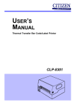
Download Citizen Systems CLP-9001 User's Manual
Transcript
CLP-9001/9301 User's Manual FCC COMPLIANCE STATEMENT FOR AMERICAN USERS This equipment has been tested and found to comply with the limits for a Class A digital device, pursuant to Part 15 of the FCC Rules. These limits are designed to provide reasonable protection against harmful interference when the equipment is operated in a commercial environment. This equipment generates, uses, and can radiate radio frequency energy and, if not installed and used in accordance with the instruction manual, may cause harmful interference to radio communications. Operation of this equipment in a residential area is likely to cause harmful interference in which case the user will be required to correct the interference at his own expense. COMPLIANCE STATEMENT FOR EUROPEAN USERS −i− EMI COMPLIANCE STATEMENT FOR CANADIAN USERS This Class A digital apparatus complies with Canadian ICES-003. This equipment generates and uses radio frequency energy and if not installed and used properly, that is, in strict accordance with the manufacturer's instructions, may cause interference to radio and television reception. This digital apparatus does not exceed the Class A limits for radio noise emissions from digital apparatus set out in the Radio Interference Regulations of the Canadian Department of Communications. This equipment is designed to provide reasonable protection against such interference in a residential installation. However, there is no guarantee that interference will not occur in a particular installation. If this equipment does cause interference to radio or television reception, which can be determined by turning the equipment off and on, the user is encouraged to try to correct the interference by one or more of the following measures: • Reorient or relocate the receiving antenna. • Increase the separation between the equipment and receiver. • Connect the equipment into an outlet on a circuit different from that to which the receiver is connected. • Consult the dealer or an experienced radio/TV technician for help. CAUTION: Use shielded cables to connect this device to computers. Any changes or modifications not expressly approved by the grantee of this device could void the user's authority to operate the equipment. ETAT DE CONFORMITE EMI A L'USAGE DES UTILISATEURS CANADIENS − ii − Important Safety Instructions 1. Read all of these instructions and save them for later reference. 2. Follow all warnings and instructions marked on the product. 3. Unplug this product from the wall outlet before cleaning. Do not use liquid or aerosol cleaners. Use a damp cloth for cleaning. 4. Do not use this product near water. 5. Do not place this product on an unstable cart, stand or table. The product may fall, causing serious damage to the product. 6. Slots and openings on the cabinet and the back or bottom are provided for ventilation. To ensure reliable operation of the product and to protect it from overheating, do not block or cover these openings. The openings should never be blocked by placing the product on a bed, sofa, rug or other similar surface. This product should never be placed near or over a radiator or heat register. This product should not be placed in a built-in installation unless proper ventilation is provided. 7. This product should be operated from the type of power source indicated on the marking label. If you are not sure of the type of power available, consult your dealer or local power company. 8. This product is equipped with a three-pronged plug, a plug having a third (grounding) pin. This plug will only fit into a grounding-type power outlet. This is a safety feature. If you are unable to insert the plug into the outlet, contact your electrician to replace your obsolete outlet. Do not defeat the safety purpose of the grounding-type plug. 9. Do not allow anything to rest on the power cord. Do not locate this product where the cord will be walked on. 10. If an extension cord is used with this product, make sure that the total of the ampere ratings on the products plugged into the extension cord do not exceed the extension cord ampere rating. Also, make sure that the total of all products plugged into the wall outlet does not exceed 15 amperes for 120V outlet and 7.5 amperes for 220−240V outlet. 11. Never push objects of any kind into this product through cabinet slots as they may touch dangerous voltage points or short out parts that could result in a risk of fire or electric shock. Never spill liquid of any kind on the product. 12. Except as explained elsewhere in this manual, don't attempt to service this product yourself. Opening and removing those covers that are marked "Do Not Remove" may expose you to dangerous voltage points or other risks. Refer all servicing on those compartments to service personnel. 13. The mains plug on this equipment must be used to disconnect mains power. Please ensure that the socket outlet is installed near the equipment and shall be easily accessible. 14. Unplug this product from the wall outlet and refer servicing to qualified service personnel under the following conditions: A. When the power cord or plug is damaged or frayed. B. If liquid has been spilled into the product. C. If the product has been exposed to rain or water. D. If the product does not operate normally when the operating instructions are followed. Adjust only those controls that are covered by the operating instructions since improper adjustment of other controls may result in damage and will often require extensive work by a qualified technician to restore the product to normal operation. E. If the product has been dropped or the cabinet has been damaged. F. If the product exhibits a distinct change in performance, indicating a need for service. − iii − Notice 1. Before use, be sure to read this manual. And keep it handy for reference when needed. 2. The contents of this manual may change without prior notice. 3. Reproduction, transfer, or transmission of the contents of this manual without prior consent is strictly prohibited. 4. We are not liable for any damage resulting from the use of the information contained herein, regardless of errors, omissions, or misprints. 5. We are not liable for any problems resulting from the use of optional products and consumable supplies other than the designated products contained herein. 6. Do not handle, disassemble or repair the parts other than those specified in this manual. 7. We are not liable for any damage caused by user's erroneous use of the printer and inadequate environment. 8. Data residing in the printer is temporary. Therefore, all data will be lost if power is lost. We are not liable for any damage or loss of profits caused by data loss due to failures, repairs, inspections, etc. 9. Please contact us if there are any mistakes or ambiguities within this manual. 10. If there are missing or incorrectly collated pages in this manual, contact us to obtain a new manual. − iv − Introduction Thank you for purchasing a new Citizen CLP series label printer. This manual is designed to help you quickly understand the basic operations of this printer. Design features This printer is designed to accurately print bar codes and various character fonts on media such as tags and labels at high speeds. Both direct thermal and thermal transfer printing is possible. • Excellent print quality at speed This printer easily creates the crisp bar codes and clear fonts required for today's vast range of labeling applications at a speed to match the performance of modern time-critical installations. • Simple control panel Printing operations such as printer setup, print position and interface configuration can be performed with the six keys on the control panel. Even an untrained operator can easily operate this printer by following the instructions on the LCD control panel. • Easy maintenance The simple construction of the printer and unobstructed view of the paper path make daily maintenance, paper and ribbon replacement, and troubleshooting quite easy and fast. • Interfacing to a computer The printer is equipped with the RS-232C serial (max. 115.2Kbps) and parallel interfaces as standard. Other interfaces such as USB, IEEE1284ECP, and Ethernet are also available as options. Using standard applications or dedicated software, bar codes and labels can easily be created and printed. • Great versatility from many options As well as the interface options, other accessories such as auto-cutter and peeler with rewinder are available to meet a diverse range of applications. −v− Table of Contents FCC Compliance Statement for American Users.............................. i Compliance Statement for European Users...................................... i EMI Compliance Statement for Canadian Users .............................. ii Important Safety Instructions ............................................................ iii Notice ................................................................................................ iv Trademark Acknowledgement........................................................... iv Introduction........................................................................................ v Design features ................................................................................. v Table of Contents .............................................................................. vi Chapter 1 Unpacking .................................................................... 1 1.1 Checking items inside the accessory box .............................. 2 Chapter 2 Safety Precautions ...................................................... 3 z Safety signs ............................................................................ 3 z Installation precautions ........................................................... 8 Chapter 3 Names and Functions of Printer Parts ...................... 9 3.1 Printer main body.................................................................... 9 3.2 Control panel .......................................................................... 12 Chapter 4 Media (Paper) and Ribbon .......................................... 15 4.1 Types of media ....................................................................... 15 4.2 Paper size ............................................................................... 18 4.3 Loading the paper................................................................... 19 4.4 Loading the ribbon .................................................................. 24 4.5 Printhead pressure adjustments............................................. 27 4.6 Paper sensor adjustments ...................................................... 28 Chapter 5 Power ON and Using the Control Panel.................... 29 5.1 Connecting to a power outlet.................................................. 29 5.2 Turning the printer ON ............................................................ 30 5.3 Ready Mode and Menu Mode ................................................ 31 5.4 Navigating the Menu System.................................................. 32 5.5 Changing Menu Values........................................................... 33 5.6 Permanently Saving Printer Settings...................................... 34 5.7 Producing a Test or Configuration Print.................................. 35 5.8 Turning the printer OFF .......................................................... 36 − vi − Chapter 6 Configuring Your Printer Using the Menus ...............37 6.1 The Group Menu .....................................................................37 6.2 Page Setup Menu ...................................................................38 6.3 System Setup Menu................................................................39 6.4 After Print Menu ......................................................................41 6.5 Interface Setup Menu..............................................................42 6.6 Permanently Saving Settings Menu........................................43 6.7 Test Mode Menu......................................................................43 6.8 Menu Mode Description ..........................................................44 Chapter 7 Troubleshooting ...........................................................49 7.1 Items to check in case of trouble ............................................49 7.2 Error messages and corrective actions ..................................51 Chapter 8 Maintenance .................................................................53 8.1 Printer care..............................................................................53 8.2 Cleaning method .....................................................................54 Chapter 9 Specifications...............................................................55 9.1 General specifications.............................................................55 9.2 Interfaces.................................................................................56 9.3 Printable area ..........................................................................59 9.4 Adjustable sensor....................................................................60 9.5 Auto-cutter (optional)...............................................................61 9.6 Peeler (optional)......................................................................62 9.7 Environmental requirements ...................................................62 − vii − − viii − Chapter 1 Unpacking Chapter 1 Unpacking First open the carton and take out the accessory box and the printer front cover, then lift the printer main body out of the carton, holding the bottom of the printer firmly. Also keep the carton and packing materials as the printer must be packed properly with the carton and packing materials for future shipment. CAUTION • When taking the printer out of the carton, prepare ample space to set the printer down. To ensure safety, no fewer than two persons should lift the printer main body at this time. • Do not hold the foam (polystyrene) dampers when lifting the printer main body. −1− Chapter 1 Unpacking 1.1 Checking items inside the accessory box First, you should check that all of the following items are inside the accessory box. If any are missing, please contact your supplier. • Power cord 1 piece • Paper core adaptor (3-inch) 2 pieces • Ribbon core 1 piece • Paper holder 1 piece • Label paper 1 piece • Ribbon bobbins 2 pieces • Ribbon 1 piece • Thermal head cleaner 1 piece • User's manual 1 copy CAUTION The specifications of the power cord may vary, depending on the rules of the destination. −2− Chapter 2 Safety Precautions Chapter 2 Safety Precautions This chapter describes safety precautions when using the printer. Please read and understand the precautions in this chapter before using the printer. z Safety signs The various safety signs included in this manual and pasted on the printer are intended to inform you of the correct and safe handling of this printer and protect against personal injury and property damage. Please familiarize yourselves with the following safety signs and their meanings. −3− Chapter 2 Safety Precautions −4− Chapter 2 −5− Safety Precautions Chapter 2 Safety Precautions −6− Chapter 2 −7− Safety Precautions Chapter 2 Safety Precautions −8− Chapter 3 Names and Functions of Printer Parts Chapter 3 Names and Functions of Printer Parts This chapter describes the names and functions of each part of the printer. 3.1 Printer main body 1 Opening/closing and detachment of the front cover To open the front cover, catch hold of the right edge of the front cover with your fingers and open it in the direction as shown with arrow. To close the front cover, return the right edge of the front cover to the original position and push it lightly and the magnet on the lower right corner will hold the front cover and the printer main body frame firmly. To remove the front cover, first open it fully then vertically lift up the hinged left side of the cover. 2 Opening/closing of the right side cover The right side cover (viewed from the front) is opened while holding the lower curved grip of the cover. The cover should be opened all the way until it stops at the hinges. To close the cover, close it fully while holding the grip of the cover and release your hand. 3 Grip to open/close the right side cover −9− Chapter 3 Names and Functions of Printer Parts CAUTION Do not touch the printhead set screw A and platen set screw B. − 10 − Chapter 3 − 11 − Names and Functions of Printer Parts Chapter 3 Names and Functions of Printer Parts 3.2 Control panel The control panel consists of an LCD displaying two lines of eight characters, two LEDs and six control keys. Two functions are assigned to each key except the MODE key. z Indications LCD (Display) Shows the current printer status by a message on the display. POWER LED Lights up when the printer power is turned on. READY LED • Lights up when the printer is placed into the print ready state. When the PAUSE key is pressed, the READY LED goes out and shows "Pause" on the LCD (Display). By pressing the PAUSE key again, the READY LED lights up. • The printer is in Ready mode after the power-on sequence has finished. • The Ready mode is selected using the MODE key. − 12 − Chapter 3 Names and Functions of Printer Parts z Control keys On the control panel legend, in Ready mode, the text written ABOVE each key shows the key's function. In Menu mode, the text written BELOW each key shows the key's function. MODE key When the MODE key is pressed, the printer is placed into the Ready mode. When the MODE key is pressed again, the printer is placed into the Menu mode. Each time the MODE key is pressed, the printer toggles between the Ready mode and Menu mode. (See P31) Key functions in the Ready mode STOP key • Shows "JobClear" on the LCD (Display) if data is stored in print buffer. • Completes printing midway through the print job or data processing and shows "JobClear Yes/No" on the LCD (Display). • Pressing STOP again changes the selection of "Yes/No" under the display of "Job Clear". FEED key • Feeds one sheet of paper when this key is pressed after TOF (top-of-form) positioning has been performed. • Performs TOF (top-of-form) positioning if the printer is part way through a label or page. Note: Sometimes the paper may be set at irregular position when it is being loaded or the power to the printer is turned on. If this occurs, press the FEED key to advance the paper to the top of the next label or page. PAUSE key • Completes current page printing midway through the print job and places the printer into paused status. To resume printing, press the PAUSE key again. • Places the printer into paused state if it is waiting to receive data from the host computer. FUNCTION key This is a reserved key; no operation is performed. REPEAT key • Reprints one job of the last printed label each time this key is pressed if the last print data is stored in print buffer and is not printed yet. • Performs no operation if no print data is stored in print buffer or printer is in printing state. − 13 − Chapter 3 Names and Functions of Printer Parts MODE key Printer enters the Menu mode, and the '∗ Page Setup' menu is shown on the LCD (Display). (See P31) Key functions in the Menu mode MENU key Selects the next Group Menu or Menu Item. (See P31 − 33) UP key • Selects the next Group Menu or Menu Item. (See P31 − 33) • Selects the next Value of the Menu Item. (See P31 − 33) DOWN key • Selects the previous Group Menu or Menu Item. (See P31 − 33) • Selects the previous Value of the Menu Item. (See P31 − 33) SELECT key • Enters the Menu Item from the Group Menu. (See P31 − 33) • Enters or exits the Value from the Menu Item. (See P31 − 33) • Executes current setting of the Value, for example, "Printing Sample" in Test mode. (See P35) EXIT key Return to the Menu Item or Group Menu. (See P31 − 33) MODE key Return to the Ready mode and the 'READY' is shown on the LCD (Display). (See P31, 32) − 14 − Chapter 4 Media (Paper) and Ribbon Chapter 4 Media (Paper) and Ribbon This chapter describes all of the types of media available for this printer and how to load the media and ribbon. Unless otherwise specified, the term 'media,' 'paper,' 'page,' 'labels' or 'tags' is referring to any media that is being printed using the printer. 4.1 Types of media We recommend that you should use a genuine Citizen paper or its equivalent. Types of media available for this printer: • Center-punched hole tag • Labels with inter-label gap • Black mark tag • Black mark label • Corner-with-a-radius cut tag z Tag Media without adhesive material on the back are referred to as tags, which are often used by cutting pieces with an optional cutter. The holes are usually arranged on the cut-off line. − 15 − Chapter 4 Media (Paper) and Ribbon ♦ Center-punched hole tag Holes (2.5mm diameter) are perforated lengthwise along the central line of the tag. ♦ Black mark tag Black marks are printed on the back of the tag at the center or on the right side in the direction of feed. ♦ Corner-with-a-radius cut tag The cuts on the edge of this tag are deeper than the cuts on center-hole tag. − 16 − Chapter 4 Media (Paper) and Ribbon z Label Media with adhesive material on the back are referred to as labels. Labels are peeled off the liner piece by piece and stuck to a product or item. ♦ Labels with inter-label gap There are gaps between labels. ♦ Black mark label Black marks are printed on the back of the label line on the central line or right side in the direction of feed. − 17 − Chapter 4 Media (Paper) and Ribbon 4.2 Paper size − 18 − Chapter 4 Media (Paper) and Ribbon 4.3 Loading the paper The out-wound roll of paper is the standard, although inward-wound media can also be used. See Page 23 for details. The paper core diameters for the roll of paper are 1, 3, or 4 inches. The standard core sizes are 1 and 3 inches. When using the paper with a paper core diameter of 3 inches, first insert the adaptor provided as an accessory into the paper core, slide it to the center of the paper core (the center of the paper width), and then set the paper on the paper roll shaft as shown below. When using the paper with a paper core diameter of 4 inches, the 4-inch adaptor (optional) is needed, so contact your supplier. Outward-wound 1. Open the front cover by holding the right-bottom corner of the cover. 2. Open the right side cover (viewed from the front), holding the curved grip on the lower right. The cover should be opened all the way until it stops at the hinges. CAUTION Do not release the cover midway. Premature release may cause the cover to slam shut, risking injury. − 19 − Chapter 4 Media (Paper) and Ribbon 3. Move the blue printhead lever towards the back of the printer to lift the printhead block. Push the blue paper guide roller release lever to lift the paper guide roller, and lower the paper guide. Paper guide Paper guide roller release lever Printhead lever 4. Turn the blue paper holder knob counterclockwise, and remove the paper holder from the shaft. − 20 − Chapter 4 Media (Paper) and Ribbon 5. To load the roll of paper, first insert the paper core adaptors (3-inch) into the paper core (see SUGGESTION below), where they must be positioned properly, and put those onto the paper roll shaft, pushing the roll of paper to the deepest side, then attach the paper holder to the paper roll shaft. At this time, be careful about the direction of the plate the shorter side should face down when the printer is the standard model, and up when the printer is equipped with the peeler option. Paper core adaptor Paper holder Knob Paper roll shaft (Shorter side) Paper core SUGGESTION • When the paper width is greater than 38 mm (1.5 in), use two pieces of paper core adaptor. • You may not need the 'paper core adapter' when the printer is used with outward-wound media. A better paper path may be achieved by hanging the 3- or 4-inch internal diameter roll of paper directly onto the paper roll shaft. However, caution should be exercised to ensure the media doesn't foul the optional peeler/rewinder spool, if fitted. 6. Pull the free end of the roll of paper through the mechanism as shown below. The paper path can be seen clearly when viewed from the side of the printer, passing below the open paper guide roller and open printhead. − 21 − Chapter 4 Media (Paper) and Ribbon 7. Let the edge of the roll of paper nearer to the control panel butt against the fan-shaped metal paper guide (on the deepest side) and turn the paper holder knob clockwise to lock the paper holder. Paper holder knob 8. Slide the blue paper guide to the edge of the roll of paper in the direction of feed and turn it upwards. Paper guide Edge of the roll of paper 9. Slightly pulling the paper toward you, move the blue printhead lever towards the front of the printer to lower and lock the printhead block in place. − 22 − Chapter 4 Media (Paper) and Ribbon 10. Close the right side cover and the front cover. Loading the paper is now completed. CAUTION When the inward-wound roll of paper is used, first put the roll of paper onto the paper roll shaft so that it can be wound clockwise as shown blow, then pull the end of the roll of paper through the printer as before. Inward-wound CAUTION The maximum outer diameter of the inward-wound roll of paper is 250 mm (9.84 in). The maximum outer diameter of the outward-wound roll of paper is 203 mm (8 in). − 23 − Chapter 4 Media (Paper) and Ribbon 4.4 Loading the ribbon We recommend that you should use a genuine Citizen ribbon or its equivalent. The ribbon (with paper core) is loaded into the printer using the two ribbon bobbins supplied. The ribbon passes from the source ribbon core (unused) to the destination core of used ribbon. 1. Open the front cover by pulling the right hand side of the cover towards you. 2. Open the right side cover (viewed from the front), holding the curved grip on the lower right of the cover. The cover should be opened all the way until it stops at the hinges. CAUTION Do not release the cover midway. Premature release may cause the cover to slam shut, leading to injury. 3. Turn the blue printhead lever clockwise to lift the printhead block. At this time, the paper guide roller should be kept closed. The ribbon now can be loaded. − 24 − Chapter 4 Media (Paper) and Ribbon 4. Insert the bobbins into the source ribbon and destination paper cores respectively. 5. Fit the destination paper core with the bobbin on the left side ribbon shaft holder and click into position. 6. Feed the ribbon bobbin a certain length and set it on the right side ribbon shaft holder and click into position. 7. Pass the ribbon through the lower side of the printhead block onto the destination ribbon core. At this time, the end of the ribbon is stuck to the destination ribbon core using the adhesive leader supplied with our genuine consumables. Alternatively, clear adhesive tape may be used. Remove any slack in the ribbon by winding the destination ribbon core clockwise. Adhesive leader (or clear adhesive tape) 8. Turn the blue printhead lever counterclockwise to lock the printhead block. − 25 − Chapter 4 Media (Paper) and Ribbon 9. Close the right side cover and then close the front cover, allowing the magnetic catch to firmly hold the front cover. The ribbon is now loaded. NOTE The following procedure may help you load the ribbon more easily. First insert the bobbins into the source and destination ribbon cores, affix the adhesive tape at the end of the ribbon and then wind the ribbon around the bobbin until the tape is hidden. Finally, set the ribbon by passing it through the lower side of the printhead block. CAUTION Be sure to wind the ribbon sufficiently over the adhesive leader (or clear adhesive tape) being fastened to the end of the ribbon before closing the right side cover. − 26 − Chapter 4 Media (Paper) and Ribbon 4.5 Printhead pressure adjustments The paper width for this printer is 19-115 mm (0.75-4.53 in). When a narrow width of paper or thick media is used, the printhead pressure across the print area is not even so poor print quality etc may occur. Before making adjustments, the paper must be loaded and the printhead block be lowered and locked. If the ribbon is loaded, the front bobbin should be removed and laid down in front of the printer. When using paper with a width of 115 mm (4.53 in) the standard printhead pressure position is about 1 mm (0.039 in) above the bottom of the gauge pointed out by the printhead pressure pointer. When narrow-width paper is used, reduce the printhead pressure on the no paper section by turning the printhead pressure knob counterclockwise. When making printhead pressure adjustments, check the paper width, paper thickness, and presence/absence of a ribbon. Printhead pressure knob* Printhead pressure gauge * To increase printhead pressure, turn printhead pressure knob clockwise. To decrease printhead pressure, turn printhead pressure knob counterclockwise. − 27 − Chapter 4 Media (Paper) and Ribbon 4.6 Paper sensor adjustments Using the paper sensor adjust-knob, adjustments to the paper sensor can be made to suit the kind of media that is being used. Before making adjustments, the paper must be loaded and the pinch roller be lowered. The two holes in the sensor arm correspond to the two different sensor positions, i.e., a hole 'R' for the reflective sensor and a hole 'T' for the transparent sensor. When using black mark tag or label paper, align the R hole with the black mark. When using corner-with-a-radius cut tag or gap label paper, align the T hole with the cut or gap. The paper sensors are moved away from you by turning the paper sensor adjust-knob (white) counterclockwise and towards you by turning the paper sensor adjust-knob clockwise. Paper sensor adjust-knob − 28 − Chapter 5 Power ON and Using the Control Panel Chapter 5 Power ON and Using the Control Panel After loading the paper and ribbon, connect the power cord and turn your printer on. 5.1 Connecting to a power outlet First plug the power cord into the AC power input on the back of the printer, then plug the other end of the power cord into the AC power outlet. CAUTION The specifications of the power cord may vary, depending on the rules of the destination. − 29 − Chapter 5 Power ON and Using the Control Panel 5.2 Turning the printer ON Turn ON the power switch. • Press "|" for ON. • Press "O" to turn off the printer. Once the power is turned ON, the following initial messages are displayed on the screen for about three seconds. − 30 − Chapter 5 Power ON and Using the Control Panel 5.3 Ready Mode and Menu Mode This section describes the operation flow of the Ready mode and Menu mode. This printer can be easily operated using the six keys on the control panel. − 31 − Chapter 5 Power ON and Using the Control Panel 5.4 Navigating the Menu System − 32 − Chapter 5 5.5 Changing Menu Values − 33 − Power ON and Using the Control Panel Chapter 5 Power ON and Using the Control Panel 5.6 Permanently Saving Printer Settings − 34 − Chapter 5 Power ON and Using the Control Panel 5.7 Producing a Test or Configuration Print − 35 − Chapter 5 Power ON and Using the Control Panel 5.8 Turning the printer OFF − 36 − Chapter 6 Configuring Your Printer Using the Menus Chapter 6 Configuring Your Printer Using the Menus This chapter explains all the possible menu options for configuring the barcode printer. Refer to Chapter 5 for information on the operation of the menus system and which keys perform which actions. 6.1 The Group Menu − 37 − Chapter 6 Configuring Your Printer Using the Menus 6.2 Page Setup Menu − 38 − Chapter 6 6.3 System Setup Menu − 39 − Configuring Your Printer Using the Menus Chapter 6 Configuring Your Printer Using the Menus − 40 − Chapter 6 6.4 After Print Menu − 41 − Configuring Your Printer Using the Menus Chapter 6 Configuring Your Printer Using the Menus 6.5 Interface Setup Menu − 42 − Chapter 6 Configuring Your Printer Using the Menus 6.6 Permanently Saving Settings Menu 6.7 Test Mode Menu − 43 − Chapter 6 Configuring Your Printer Using the Menus 6.8 Menu Mode Description − 44 − Chapter 6 − 45 − Configuring Your Printer Using the Menus Chapter 6 Configuring Your Printer Using the Menus − 46 − Chapter 6 − 47 − Configuring Your Printer Using the Menus Chapter 6 Configuring Your Printer Using the Menus − 48 − Chapter 7 Troubleshooting Chapter 7 Troubleshooting When an error occurs, an error message is displayed on the LCD panel. This chapter describes corrective actions to be taken when error message is received or problems or difficulties are experienced. 7.1 Items to check in case of trouble If problems or difficulties are experienced during the operation of the printer, please check the following table to try and resolve your problem. − 49 − Chapter 7 Troubleshooting − 50 − Chapter 7 7.2 Error messages and corrective actions − 51 − Troubleshooting Chapter 7 Troubleshooting − 52 − Chapter 8 Maintenance Chapter 8 Maintenance Since this printer uses a thermal head and a carbon ink ribbon, thermal paper dust etc may adhere to the printhead or other related parts. In this case, printing errors or failure of the printhead may occur. If paper dust or ribbon material adheres to the printhead, irregular printer movements, paper jams or poor print quality may occur. Therefore, be sure to clean the printhead, platen and paper path periodically. The amount of cleaning will depend on the volume of media being printed and the quality of the consumables and media used in the printer. Genuine Citizen consumables will be you the best performance. If a defect should occur under normal use, it will be repaired free of charge during the warranty period. However, the printhead, platen and pinch roller will be regarded as consumable supplies. 8.1 Printer care Observe the following when caring for the printer. • Use a cotton swab or soft cloth to clean each part of the printer. • Hard or square tools such as screwdrivers can scratch any part of the printer. Never clean the printhead with such tools. • Before cleaning, make sure that the power to the printer is turned OFF and the power cord is disconnected from the mains supply. − 53 − Chapter 8 Maintenance 8.2 Cleaning method − 54 − Chapter 9 Chapter 9 Specifications 9.1 General specifications − 55 − Specifications Chapter 9 Specifications 9.2 Interfaces 1 Serial interface Specifications Transfer method: Start stop synchronous dual communication system Signal level: RS-232C Baud rate: 2400, 4800, 9600, 14400, 19200, 38400, 57600, 115200 bps Data bits: 7 or 8 Start bits: 1 Stop bits: 1 or 2 Parity: Even, odd, or none Connector: D-SUB 25PIN 17LE-13250-27(D41)(DDK) or its equivalent XON/XOFF protocol XON code output requirements: • Communication is enabled after power is turned ON. • Residual capacity of the buffer is 1K bytes or more after sending XOFF code. • XOFF code is output due to error and printer returns to normal conditions. XOFF code output requirements: • Printer is in error. • Printer is in paused state. • Receive buffer has less than 128 bytes available. − 56 − Chapter 9 Specifications DTR protocol DTR signal "Ready (High)" level requirements: The following must be satisfied: • Printer is on line. • Receive buffer has more than 1K bytes available. Note: When receive buffer has less than 128 bytes available, DTR signal becomes "Busy (Low)" level and this "Busy (Low) level is kept until receive buffer has at least 1K bytes available. DTR signal "Busy (Low)" level requirements: The following must be satisfied: • Printer is in error. • Receive buffer has less than 128 bytes available. Pin assignment − 57 − Chapter 9 Specifications 2 Parallel interface Specifications Transfer method: 8-bit parallel (compatibility mode) Synchronous: Strobe pulse Handshaking: ACKNLG and BUSY signals Signal level: TTL Printer side: 36-pin non-phenol type Pin assignment − 58 − Chapter 9 9.3 Printable area The accurate print position is illustrated below. − 59 − Specifications Chapter 9 Specifications 9.4 Adjustable sensor − 60 − Chapter 9 9.5 Auto-Cutter (optional) − 61 − Specifications Chapter 9 Specifications 9.6 Peeler (optional) Peeler specifications Paper width: 115 mm (4.53 in) Maximum diameter of paper roll: 203 mm (8 in) Minimum inner diameter of paper roll: 76 mm (3 in) Maximum label length: 120 mm (4.72 in) Minimum label length: 25.4 mm (1 in) Maximum paper thickness: 0.17 mm (0.067 in) Maximum liner thickness: 0.07 mm (0.0027 in) 9.7 Environmental requirements − 62 − Citizen America Corporation 831 S. Douglas Street, Suite 121 El Segundo, CA 90245 Tel: (310) 643-9825 U.S.A. Citizen Systems Europe GmbH http://www.citizen-europe.com Mettinger Strasse 11 Park House 73728 Esslingen 643-651 Staines Road, Feltham Germany Middlesex, TW14 8PA United Kingdom Japan CBM Corporation CBM Bldg., 5-68-10, Nakano Nakano-ku, Tokyo 164-0001 Tel: (+81-3) 5345-7540 Fax:(+81-3) 5345-7541 Japan JK74901-20 Printed in Japan


