1
Configuring Cisco uBR7246 Universal
Broadband Router Features
Cisco uBR7246 universal broadband features enable the Cisco uBR7246 universal broadband router
to communicate with a hybrid fiber coaxial (HFC) cable network via a Cisco MC11 cable modem
card. Cisco MC11 cable modem cards allow you to connect cable modems on the HFC network to
a Cisco uBR7246 in a Community Antenna Television (CATV) headend facility. The modem card
provides the interface between the Cisco uBR7246 protocol control information (PCI) bus and the
radio frequency (RF) signal on the HFC network. For a description of the commands used to
configure universal broadband features, refer to the “Cisco uBR7246 Universal Broadband Features
Commands” chapter in the Voice, Video, and Home Applications Command Reference.
The MC11 cable modem cards consist of the following components:
•
One downstream cable F-connector port—The downstream port supports quadrature amplitude
modulation (QAM) speeds of 64-QAM, or 6 bits per symbol. A symbol is the basic unit of
modulation in CATV systems.
•
One upstream cable F-connector port—The upstream port supports quadrature phase shift keying
(QPSK) modulation, or 2 bits per symbol.
•
Cable Media Access Control (MAC) unit—The cable MAC frames and encrypts the downstream
signal for RF transmission and passes the signal to the downstream physical layer (PHY).
Reverses the signal framing and encryption on the upstream signal from the upstream PHY.
•
Downstream PHY unit—The downstream PHY generates a modulated, intermediate frequency
(IF) output signal at a frequency of 44 MHz and passes the IF signal to an external IF to RF
upconverter installed in the downstream path.
•
Upstream PHY unit—The upstream PHY receives the modulated, upstream signal at a frequency
of 5 MHz to 40 MHz and passes the signal to the cable MAC to remove the framing and
encryption formats.
•
Spectrum manager—The spectrum manager continuously monitors the noise in unused upstream
channels. If the signal-to-noise ratio reaches an unacceptable level on a particular channel, the
spectrum manager will automatically assign a new upstream channel to the cable modem using
that channel. This feature is referred to as frequency agility.
You must install at least one Cisco MC11 cable modem card in the Cisco uBR7246 chassis to
establish communication between the Cisco uBR7246 and the HFC network.
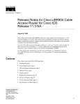
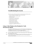
Figure 38 shows the network topology for the modem card and illustrates network connections using
the Cisco uBR7246.
Configuring Cisco uBR7246 Universal Broadband Router Features VC-133
Figure 38
Topology for uBR7246 Universal Broadband
Internet
WAN
ATM, 100BT, 10BT
100BT
100BT
Proxy server
Cisco
uBR7246
ISP
100BT
IF
MSO: Multiple Service Organization
US-RF
Analog TV
5-42 MHz
signals
Upconverter
RF
DS-RF 54-860 Mhz
Combiner
Digital TV
signals
Fiber
Transceiver
80 km
1000 ft
Fiber node
(Telephone pole,
underground box)
Tap
VC-134
Voice, Video, and Home Applications Configuration Guide
Cable modem
(Cisco uBR904)
11278
Drop box
Two-way
distribution
amplifier
Description of Cisco uBR7246 Cable Router
Description of Cisco uBR7246 Cable Router
As shown in Figure 38, the Cisco uBR7246 serves as an interface between a WAN backbone and an
HFC cable plant. Typically installed at a CATV headend, the Cisco uBR7246 is often located with
the following internet service provider-related components:
•
•
•
Ethernet switch
Proxy server
WAN Router
The Ethernet switch is used to reduce traffic on the WAN backbone.
The proxy server usually functions as a Web cache for host computers, and the DHCP/TFTP server
for cable modems. DHCP for host computers in the HFC plant is often handled over the WAN. The
WAN router provides a gateway to the data network.
On the RF side, the downstream port is assigned a 6-8 MHz channel slot at a standard broadcast
CATV frequency. An upconverter device is used to convert the 44 MHz intermediate frequency (IF)
output to the assigned slot. In North America, carrier frequencies in the forward plant are assigned
between 54-860 MHz. After upconversion, the signal is combined with other analog TV or digital
TV signals and sent to the transmit input of a fiber transceiver.
The receive input of the fiber transceiver is connected to an upstream port of the Cisco uBR7246.
The upstream port is assigned a 0.2-3.2 MHz frequency band in the reverse plant. In North America,
carrier frequencies in the reverse plant are between 5-42 MHz.
The fiber transceiver is connected to up to 80 kilometers of optical fiber. Signals are carried in analog
form to a neighborhood where they terminate in a fiber node. The fiber node, located on a telephone
pole or in an underground box, converts the optical signal back to an electrical signal, which is
passed on to a two-way, distribution amplifier system. The distribution amplifier system passes
through the neighborhood where it is tapped off to individual CATV subscribers. Typically, there are
500-1500 homes passed per fiber node.
A coaxial cable delivers the signal from the tap to a subscriber’s drop box. From the drop box, the
signal is split and cabled to consumer CATV appliances. In addition to analog or digital television,
the subscriber obtains data services using a cable modem appliance, like the Cisco uBR904 cable
modem.
Benefits of Cisco uBR7246
The Cisco uBR7246 features bring value to the digital broadband network by:
•
Enabling the cost-effective deployment of advanced routing capabilities deep into the cable
network.
•
Combining the power and functionality of a Cisco 7200 series router with the high-speed network
access of a Cable Modem Termination Shelf (CMTS). By combining these two essential
functions, the Cisco uBR7246 router conserves valuable headend rack space, and it allows cable
operators to deploy routing capability in every CMTS location, which improves network
performance.
Configuring Cisco uBR7246 Universal Broadband Router Features VC-135
List of Terms
•
Providing a universal platform for deployment of both current and future modem technologies
via modular upgrades while protecting the operator’s invested capital.
•
Leveraging Cisco’s industry-standard routing hardware and Cisco IOS software to deliver
advanced network services and applications. The Cisco uBR7246 uses the same port adapters as
the Cisco 7500 and Cisco 7200 series routers, and they are fully interchangeable. This
adaptability and flexibility allows the operator to configure the network with any interface
desired, including Ethernet, Fast Ethernet, FDDI, ATM, packet-over-SONET, and serial.
The Cisco uBR7246 cable modem cards are fully compatible with the Data Over Cable System
Interface Specification (DOCSIS) established by major North American cable operators through the
Multimedia Cable Network System (MCNS) consortium.
The Cisco uBR7246 supports both two-way and telephone return modems on a single downstream
channel. The Cisco uBR7246 therefore allows both one-way and two-cable plants to provide cable
modem service, and gives cable operators the flexibility to roll out service in systems that are only
partially upgraded to two-way.
List of Terms
Community Antenna Television (CATV)—Broadband transmission facility.
Downstream—Frequency multiplexed band in a CATV channel that distributes signals from
headend to users. In this instance, downstream refers to the data flow from the Cisco MC11 modem
card in a Cisco uBR7246 to the user’s cable modem.
Headend—Originating point of a signal in a Cable TV system.
IF—Intermediate frequency. Intermediate electromagnetic frequencies generated by a
superheterodyne radio receiver.
HFC—Hybrid fiber coaxial cable. Distribution cabling concept using both fiber optic and coaxial
cable. Fiber is used for the backbone distribution medium, terminating in a remote unit where
optoelectrical conversion takes place. The signal is then passed as data to coaxial cables that carry it
to its destination.
QAM—Quadarture amplitude modulation. Modulation technique that allows data-encoded symbols
to be represented in 16 or 32 different states.
QPSK—Quaternary phase shift keying. Compression technique used in modems and wireless
networks, allowing the transmission of 2 bits per symbol. QPSK provides a 2:1 compression ratio,
resulting in double efficiency for the circuit being used.
RF—Radio frequency. Group of electromagnetic energy whose wavelengths are between the audio
and light range, usually between 500 KHz and 300 GHz.
Symbol—Phase range of a sine wave.
Upstream—Frequency multiplexed band in a CATV channel that distributes signals from
transmitting stations to headend. In this instance, upstream refers to the data flow from a cable
modem to the Cisco MC11 modem card in a Cisco uBR7246.
VC-136
Voice, Video, and Home Applications Configuration Guide
List of Terms
Prerequisite Tasks
Before you can configure Cisco uBR7246 universal broadband router features, you must first:
•
Make sure that your current network is designed to support broadband transmission. At the very
least, your network must include the following:
— Computer on the WAN side of your Cisco uBR7246 configured as a DHCP server to assign
IP addresses to cable modems on the HFC network.
— Cisco uBR7246-compatible IF-to-RF upconverter installed in the downstream data path at
your headend site. The upconverter is installed between the Cisco uBR7246 and the
combiner.
Note The combiner refers to all cables, amplifiers, and taps at the headend or cable distribution
center that connect the Cisco uBR7246 to the hybrid fiber coaxial (HFC) network.
— Diplex filters installed in the downstream RF path between the cable modems and the cable
modem cards in the Cisco uBR7246. Diplex filters are used to convert the single,
bidirectional signals used by cable modems to the two, separate unidirectional signals used
by the cable modem cards.
— RG-59 headend coaxial cable with the maximum braid available (60% + 40% braid), double
foil, and the correct connector for this cable. The center conductor must be straight and
extend 1/8 inch (3.2 mm) beyond the end of the connector and the connector should be
securely crimped to the cable.
•
Complete a basic configuration of the Cisco uBR7246. This includes, as a minimum, the
following tasks:
— Configure a host name and password for the Cisco uBR7246. For more information about
how to configure a host name and password, refer to the Cisco uBR7246 Universal
Broadband Router Installation and Configuration Guide.
— Configure the Cisco uBR7246 to support IP. For more information about how to configure
IP, refer to the refer to the “IP Overview,” “Configuring IP Addressing,” and “Configuring IP
Services” chapters in the Network Protocols Configuration Guide, Part 1.
— Install and configure at least one port adapter to provide WAN connectivity. The
Cisco uBR7246 supports the following port adapters: 4-port 10BASE-T Ethernet, 8-port
10BASE-T Ethernet, 100BASE-T Fast Ethernet, ATM, and HSSI.
For information about installing and configuring the 4-port 10BASE-T port adapter, refer to
the 4-E Ethernet 10BASE-T Port Adapter Installation and Configuration document.
For information about installing and configuring the 8-port 10BASE-T port adapter, refer to
the 8-E Ethernet 10BASE-T Port Adapter Installation and Configuration document.
For information about installing and configuring the 100BASE-T Fast Ethernet port adapter,
refer to the 100BASE-T Fast Ethernet Port Adapter Installation and Configuration
document.
For information about installing and configuring the ATM port adapter, refer to the ATM Port
Adapter Installation and Configuration document.
For information about installing and configuring the HSSI port adapter, refer to the HSSI Port
Adapter Installation and Configuration document.
Configuring Cisco uBR7246 Universal Broadband Router Features VC-137
Configure the Downstream Cable Interface
•
Install at least one Cisco MC11 cable modem card in the appropriate slot of Cisco uBR7246
chassis. For information about installing the Cisco MC11 cable modem card, refer to the
Cisco uBR7246 Universal Broadband Router Cable Modem Card Installation and Configuration
document.
Supported MIBs and RFCs
The Cisco uBR7246 universal broadband features support the RF Interface Management
Information Base (MIB). No RFCs are supported by this feature.
Universal Broadband Features Configuration Task List
The Cisco IOS software command-line interface (CLI) is used to configure the Cisco MC11 cable
modem card for correct operation on the HFC network. Perform the following tasks to configure the
MC11 cable modem card. For some tasks, the default values are adequate to configure the device;
these configuration tasks are optional.
•
•
•
•
•
•
•
•
Configure the Downstream Cable Interface (Optional)
Configure the Upstream Cable Interface
Configure and Activate Baseline Privacy
Configure and Activate Frequency Agility
Activate IP Address Resolution Protocol (Optional)
Activate Host-to-Host Communication (Proxy ARP) (Optional)
Set Optional IP Parameters (Optional)
Manage Cable Modems on the HFC Network (Optional)
Configure the Downstream Cable Interface
The first step in configuring the MC11 cable modem interface is to configure the downstream cable
interface. In this case, downstream refers to the data flow from the Cisco MC11 modem card in a
Cisco uBR7246 to the user’s cable modem. Data passing through the MC11 cable modem card is
converted to IF and then run through an upconverter to transform the signal to RF. This RF signal is
then sent down the line to the user’s cable modem. Downstream cable interface commands configure
the frequency, symbol rate, compression, and modulation of the downstream signal.
Perform the following tasks to configure the downstream cable interface:
•
•
•
•
•
•
VC-138
Set the Downstream Center Frequency
Set the Downstream Symbol Rate
Set the Downstream MPEG Framing Format (Annex A or Annex B)
Set the Downstream Modulation
Set the Downstream Interleave Depth
Activate the Downstream Carrier
Voice, Video, and Home Applications Configuration Guide
Set the Downstream Center Frequency
Note The default values for the commands used in these configuration steps are, in most cases,
adequate to configure the Cisco uBR7246.
Set the Downstream Center Frequency
You need to set the downstream frequency of your RF output to comply with the expected input
frequency of your upconverter. To do this, enter the fixed center frequency of the downstream RF
carrier for a downstream port.
Downstream frequency is an information-only command that should reflect the digital carrier
frequency, which is the center frequency of the downstream RF carrier (the channel) for that
downstream port. The configuration controlling the digital carrier frequency is done in the IF-to-RF
upconverter that must be installed in the downstream path from the Cisco uBR7246. Refer to the
upconverter’s manufacturer’s instructions for information about configuring the upconverter.
The digital carrier frequency is specified to be the center of a 6.0 MHz channel. For example, EIA
channel 95 spans 90.000 to 96.000 MHz. The center frequency is 93.000 MHz, which is the digital
carrier frequency that should be configured as the downstream frequency.
Note The digital carrier frequency is not the same as the video carrier frequency. For EIA channel
95, the video carrier frequency is 91.250 MHz, which is 1.75 MHz below the center frequency.
Note This command currently has no effect on external upconverters; it is informational only.
To set the downstream center frequency, use the following command in cable interface configuration
mode:
Command
Purpose
cable downstream frequency down-freq-hz
Enter the fixed center frequency for your downstream
RF carrier in Hz.
Validation Tips
To verify the current value of the center frequency, enter the show controllers cable command for
the downstream port that you have just configured:
•
If the center frequency is fixed, the actual frequency will be displayed:
router# show controllers cable 6/0 downstream
Cable6/0 Downstream is up
Frequency=96000000, Channel Width 6 MHz, 64-QAM, Symbol Rate 5.056941 Msps
FEC ITU-T J.83 Annex B, R/S Interleave I=32, J=4
•
If the center frequency is not fixed, the frequency will show that it is not set:
router# show controllers cable 6/0 downstream
Cable6/0 Downstream is up
Frequency is not set. Channel Width 6 MHz, 64-QAM, Symbol Rate 5.056941 Msps
FEC ITU-T J.83 Annex B, R/S Interleave I=32, J=4
Configuring Cisco uBR7246 Universal Broadband Router Features VC-139
Configure the Downstream Cable Interface
Troubleshooting Tips
If you are having trouble:
•
•
•
•
Make sure the cable connections are not loose or disconnected.
Make sure the cable modem card is firmly seated in its Cisco uBR7246 chassis slot.
Make sure that you have entered the correct slot and port numbers when you typed the command.
Make sure you have calculated and entered the center frequency for your headend accurately.
Set the Downstream Symbol Rate
You need to set the megasymbols per second (Msps) rate for a downstream port on a cable modem
card. A symbol is the basic unit of modulation. QPSK encodes 2 bits per symbol, 16-QAM encodes
4 bits per symbol, 64-QAM encodes 6 bits per symbol, and 256-QAM encodes 8 bits per symbol.
The valid range for the downstream symbol rate is 0 to 6,000,000 Msps.
The default downstream symbol rate is set to comply with MCNS specifications for Annex B
cable modem support at 5.056941 Msps with 64-QAM modulation and 5.36037 Msps with 256-QAM
modulation. This command should only be used to change the symbol rate to support Annex A cable modems
that are used outside North America.
Caution
To set the downstream symbol rate, use the following command in cable interface configuration
mode:
Command
Purpose
cable downstream symbol-rate number
Set the downstream symbol rate for Annex A
(5.056944 Msps). Do not enter the decimal point in the
symbol rate.
Validation Tips
To verify the downstream symbol rate, enter the show controllers cable command for the
downstream port that you have just configured:
router# show controllers cable 6/0 downstream
Cable6/0 Downstream is up
Frequency=96000000, Channel Width 6 MHz, 64-QAM, Symbol Rate 5.056941 Msps
FEC ITU-T J.83 Annex B, R/S Interleave I=32, J=4
Troubleshooting Tips
If you are having trouble:
VC-140
•
•
•
•
•
Make sure the cable connections are not loose or disconnected.
•
Make sure the downstream carrier is active by entering the cable downstream if-output
command.
Make sure the cable modem card is firmly seated in its Cisco uBR7246 chassis slot.
Make sure that you have entered the correct slot and port numbers when you typed the command.
Make sure you have selected the default if you are using Annex B cable modems.
Make sure that you have entered the correct symbol rate for Annex A specifications if you are
using Annex A cable modems. Do not enter the decimal point when entering the symbol rate.
Voice, Video, and Home Applications Configuration Guide
Set the Downstream MPEG Framing Format (Annex A or Annex B)
Set the Downstream MPEG Framing Format (Annex A or Annex B)
The MPEG framing format must be compatible with the downstream symbol rate you set. Set the
MPEG framing format for a downstream port on a cable modem card to either Annex A or Annex B.
Annex B is the North America standard and Annex A is the European standard. You should review
your local standards and specifications for downstream MPEG framing to determine which format
you should use.
Note The cable modem card downstream ports and the cable modems on the HFC network
connected through these ports must be set to the same MPEG framing format.
To set the downstream MPEG framing format, use the following command in cable interface
configuration mode:
Command
Purpose
cable downstream annex {A | B}
Set the downstream MPEG framing format.
Validation Tips
To verify the downstream MPEG framing format (Annex A or Annex B) setting, enter the show
controllers cable command for the downstream port that you have just configured:
router# show controllers cable 6/0 downstream
Cable6/0 Downstream is up
Frequency=96000000, Channel Width 6 MHz, 64-QAM, Symbol Rate 5.056941 Msps
FEC ITU-T J.83 Annex B, R/S Interleave I=32, J=4
Troubleshooting Tips
If you are having trouble:
•
•
•
•
•
Make sure the cable connections are not loose or disconnected.
Make sure the cable modem card is firmly seated in its Cisco uBR7246 chassis slot.
Make sure that you have entered the correct slot and port numbers when you typed the command.
Make sure you have selected the correct setting for your location.
Make sure the downstream carrier is active by entering the cable downstream if-output
command.
Set the Downstream Modulation
Downstream modulation is the number of symbols per second; by setting the downstream
modulation, you define the speed at which data travels downstream to the user, which is 64 qam
(6 bits per downstream symbol rate).
Note The Cisco cable modem cards currently do not offer a downstream modulation setting for
256-QAM (8 bits per downstream symbol rate).
Configuring Cisco uBR7246 Universal Broadband Router Features VC-141
Configure the Downstream Cable Interface
To set the downstream modulation, use the following command in cable interface configuration
mode:
Command
Purpose
cable downstream modulation 64qam
Set the standard MCNS rate.
Validation Tips
To verify the downstream modulation setting, enter the show controllers cable command for the
downstream port that you have just configured:
router# show controllers cable 6/0 downstream
Cable6/0 Downstream is up
Frequency=96000000, Channel Width 6 MHz, 64-QAM, Symbol Rate 5.056941 Msps
FEC ITU-T J.83 Annex B, R/S Interleave I=32, J=4
Troubleshooting Tips
If you are having trouble:
•
•
•
•
•
Make sure the cable connections are not loose or disconnected.
Make sure the cable modem card is firmly seated in its Cisco uBR7246 chassis slot.
Make sure that you have entered the correct slot and port numbers when you typed the command.
Make sure you have selected the default if you are not certain about the modulation rate needed.
Make sure the downstream carrier is active by entering the cable downstream if-output
command.
Set the Downstream Interleave Depth
The next step is to set the interleave depth for a downstream port on a cable modem card. A higher
interleave depth provides more protection from bursts of noise on the HFC network; however, it will
increase downstream latency. The valid values are 8, 16, 32 (default), 64, and 128.
To set the downstream interleave depth, use the following command in cable interface configuration
mode:
Command
Purpose
cable downstream interleave-depth {8 | 16 | 32 | 64 | 128}
Set the downstream interleave depth.
Validation Tips
To verify the downstream interleave depth setting, enter the show controllers cable command for
the downstream port that you have just configured:
router# show controllers cable 6/0 downstream
Cable6/0 Downstream is up
Frequency=96000000, Channel Width 6 MHz, 64-QAM, Symbol Rate 5.056941 Msps
FEC ITU-T J.83 Annex B, R/S Interleave I=32, J=
VC-142
Voice, Video, and Home Applications Configuration Guide
Activate the Downstream Carrier
Troubleshooting Tips
If you are having trouble:
•
•
•
•
Make sure the cable connections are not loose or disconnected.
Make sure the cable modem card is firmly seated in its Cisco uBR7246 chassis slot.
Make sure that you have entered the correct slot and port numbers when you typed the command.
Make sure the downstream carrier is active by entering the cable downstream if-output
command.
Activate the Downstream Carrier
To activate a downstream port on a cable modem card for digital data transmissions over the HFC
network, use the following commands in global configuration mode:
Step
Command
Purpose
1
interface cable port/slot
Specify a cable interface and enter the cable interface
configuration mode.
2
cable downstream if-output
Activate downstream digital data from the Cisco uBR7246.
(This is the default setting.)
Validation Tips
To verify that the downstream carrier is active (up), enter the show controllers cable command for
the downstream port that you have just configured:
router# show controllers cable 6/0 downstream
Cable6/0 Downstream is up
Frequency=96000000, Channel Width 6 MHz, 64-QAM, Symbol Rate 5.056941 Msps
FEC ITU-T J.83 Annex B, R/S Interleave I=32, J=4
Troubleshooting Tips
If you are having trouble with this configuration:
•
•
•
Make sure the cable connections are not loose or disconnected.
Make sure the cable modem card is firmly seated in its Cisco uBR7246 chassis slot.
Make sure that you have entered the correct slot and port numbers when you typed the command.
Configuring Cisco uBR7246 Universal Broadband Router Features VC-143
Configure the Upstream Cable Interface
Configure the Upstream Cable Interface
The next step is to configure the upstream cable interface. In this case, upstream refers to the data
flow from a cable modem to the Cisco MC11 modem card in a Cisco uBR7246. The user’s cable
modem sends an RF signal back to the MC11 cable modem card, which translates the RF signal back
to data format. Upstream cable interface commands configure the frequency and input power level
of the upstream signal, in addition to error detection and correction of the upstream signal.
The configuration of the upstream cable interface depends on each cable operator’s physical plant.
Perform the following tasks to configure the upstream cable interface:
•
•
•
•
•
Set the Upstream Frequency
Set the Upstream Input Power Level
Activate Upstream Forward Error Correction
Activate the Upstream Scrambler
Activate the Upstream Ports
Set the Upstream Frequency
You need to set the upstream frequency of your RF output to comply with the expected input
frequency of your Cisco MC11 cable modem. You do this by entering a fixed frequency of the
upstream RF carrier for an upstream port. The valid range for a fixed upstream frequency is
5,000,000 Hz to 42,000,000 Hz.
Note Make sure that the upstream frequency selected does not interfere with the frequencies used
for any other upstream applications running in the cable plant.
Note The cable interface will not operate until you either set a fixed upstream frequency or create
and configure a spectrum group. See the section “Create Spectrum Groups” later in this document.
To set the upstream frequency, use the following command in cable interface configuration mode:
VC-144
Command
Purpose
cable upstream port frequency up-freq-hz
Enter the fixed center frequency for your upstream RF
carrier in Hz.
Voice, Video, and Home Applications Configuration Guide
Set the Upstream Input Power Level
Validation Tips
To verify the current value of the upstream frequency, enter the show controllers cable command
for the upstream port that you have just configured:
router# show controllers cable 6/0 u0
Cable6/0 Upstream 0 is up
Frequency 7.008 MHz, Channel Width 1.6 MHz, QPSK Symbol Rate 1.280 Msps
Nominal Input Power Level 0 dBmV, Tx Timing Offset 0
Ranging Backoff Start 0, Ranging Backoff End 4, Tx Backoff Start 0
Tx Backoff End 4, Modulation Profile Group 1
part_id=0x3136, rev_id=0x02, rev2_id=0x61
nb_agc_thr=0x0100, nb_agc_nom=0x3000
Range Load Reg Size=0x58
Request Load Reg Size=0x0C
Minislot Size in number of Timebase Ticks is = 8
Minislot Size in Symbols =64
Minislot Size in Bytes = 16
UCD Count = 361894
DES Reg #580 = E204301, #584 = 3E030303, #588 = 0.
#590 = C0C0C0C.
Troubleshooting Tips
If you are having trouble:
•
•
•
•
•
Make sure the cable connections are not loose or disconnected.
Make sure the cable modem card is firmly seated in its Cisco uBR7246 chassis slot.
Make sure that you have entered the correct slot and port numbers when you typed the command.
Make sure that you have entered the correct upstream port number. Currently this is always u0.
Make sure you have selected a valid frequency for your headend.
Set the Upstream Input Power Level
The Cisco uBR7246 controls the output power levels of the cable modems to meet the desired
upstream input power level. The default setting of 0 dBmV is the optimal setting for the upstream
power level.
Caution If you increase the input power level, the cable modems on your HFC network will increase their
transmit power level. This might cause an increase in the carrier-to-noise ratio (CNR) on the network. Be
careful if you adjust this parameter. You might violate the upstream return laser design parameters.
To set the upstream input power level, use the following command in cable interface configuration
mode:
Command
Purpose
cable upstream port power-level dbmv
Enter the upstream power level in dBmV.
Configuring Cisco uBR7246 Universal Broadband Router Features VC-145
Configure the Upstream Cable Interface
Validation Tips
To verify the current value of the upstream input power level, enter the show controllers cable
command for the upstream port that you have just configured:
router# show controllers cable 6/0 u0
Cable6/0 Upstream 0 is up
Frequency 7.008 MHz, Channel Width 1.6 MHz, QPSK Symbol Rate 1.280 Msps
Nominal Input Power Level 0 dBmV, Tx Timing Offset 0
Ranging Backoff Start 0, Ranging Backoff End 4, Tx Backoff Start 0
Tx Backoff End 4, Modulation Profile Group 1
part_id=0x3136, rev_id=0x02, rev2_id=0x61
nb_agc_thr=0x0100, nb_agc_nom=0x3000
Range Load Reg Size=0x58
Request Load Reg Size=0x0C
Minislot Size in number of Timebase Ticks is = 8
Minislot Size in Symbols = 64
Minislot Size in Bytes = 16
UCD Count = 361894
DES Reg #580 = E204301, #584 = 3E030303, #588 = 0.
#590 = C0C0C0C.
Troubleshooting Tips
If you are having trouble:
•
•
•
•
•
Make sure the cable connections are not loose or disconnected.
Make sure the cable modem card is firmly seated in its Cisco uBR7246 chassis slot.
Make sure that you have entered the correct slot and port numbers when you typed the command.
Make sure that you have entered the correct upstream port number. Currently this is always u0.
Make sure you have selected a valid input power level for your headend and the cable modems
on your HFC network.
Activate Upstream Forward Error Correction
The Cisco uBR7246 uses forward error correction (FEC) to attempt to correct any upstream data that
might have been corrupted. FEC is activated by default and should not be disabled. When FEC is
activated, all cable modems on the network also activate FEC.
To activate the upstream forward error correction, use the following command in cable interface
configuration mode:
VC-146
Command
Purpose
cable upstream port/slot fec
Enable FEC.
Voice, Video, and Home Applications Configuration Guide
Activate the Upstream Scrambler
Validation Tips
To verify if FEC is activated or deactivated, enter the command more system:running-config and
look for the cable interface configuration information. The following is an excerpt from the more
system:running-config command output.
router# more system:running-config
Building configuration...
!
interface Cable6/0
ip address 1.1.1.1 255.255.255.0
no keepalive
cable insertion-interval 150000
cable downstream annex B
cable downstream modulation 64qam
cable downstream interleave-depth 32
cable downstream symbol-rate 5056941
cable upstream 0 frequency 15008000
cable upstream 0 fec
cable upstream 0 scrambler
no cable upstream 0 shutdown
!
Troubleshooting Tips
If you are having trouble:
•
•
•
•
Make sure the cable connections are not loose or disconnected.
Make sure the cable modem card is firmly seated in its Cisco uBR7246 chassis slot.
Make sure that you have entered the correct slot and port numbers when you typed the command.
Make sure that you have entered the correct upstream port number. Currently this is always u0.
Activate the Upstream Scrambler
The scrambler on the upstream RF carrier enables cable modems on the HFC network to use built-in
scrambler circuitry for upstream data transmissions. The scrambler circuitry improves reliability of
the upstream receiver on the cable modem card. The upstream scrambler is activated by default and
should not be disabled.
Caution The Scrambler must be activated for normal operation. Deactivate only for prototype modems that
do not support scrambler.
To activate the upstream scrambler, use the following command in cable interface configuration
mode:
Command
Purpose
cable upstream port scrambler
Enable the scrambler.
Configuring Cisco uBR7246 Universal Broadband Router Features VC-147
Configure the Upstream Cable Interface
Validation Tips
To verify if the upstream scrambler is activated, enter the command more system:running-config
and look for the cable interface configuration information. The following is an excerpt from the
more system:running-config command output.
router# more system:running-config
Building configuration...
Current configuration:
!
!
interface Cable6/0
ip address 1.1.1.1 255.255.255.0
no keepalive
cable insertion-interval 150000
cable downstream annex B
cable downstream modulation 64qam
cable downstream interleave-depth 32
cable downstream symbol-rate 5056941
cable upstream 0 frequency 15008000
cable upstream 0 fec
cable upstream 0 scrambler
no cable upstream 0 shutdown
!
end
Troubleshooting Tips
If you are having trouble:
•
•
•
•
Make sure the cable connections are not loose or disconnected.
Make sure the cable modem card is firmly seated in its Cisco uBR7246 chassis slot.
Make sure that you have entered the correct slot and port numbers when you typed the command.
Make sure that you have entered the correct upstream port number. Currently this is always u0.
Activate the Upstream Ports
Activate the RF carrier on the upstream ports. Each upstream port must be activated to enable
upstream data from the cable modems on the HFC network to the Cisco uBR7246.
To activate the upstream ports, use the following commands in global configuration mode:
VC-148
Step
Command
Purpose
1
interface cable port/slot
Specify a cable interface, and enter the cable
interface configuration mode.
2
no cable upstream 0 shutdown
Enable upstream data traffic.
Voice, Video, and Home Applications Configuration Guide
Configure and Activate Baseline Privacy
Validation Tips
To verify if the upstream ports are activated or deactivated, enter the show interface cable command
for the upstream port that you have just configured:
router# show interface cable 6/0
Cable6/0 is up, line protocol is up
Hardware is BCM3210 FPGA, address is 00e0.1e5f.7a60 (bia 00e0.1e5f.7a60)
Internet address is 1.1.1.3/24
MTU 1500 bytes, BW 27000 Kbit, DLY 1000 usec, rely 255/255, load 1/255
Encapsulation, loopback not set, keepalive not set
ARP type: ARPA, ARP Timeout 04:00:00
Last input 00:00:25, output 00:00:00, output hang never
Last clearing of “show interface” counters never
Queueing strategy: fifo
Output queue 0/40, 0 drops; input queue 0/75, 0 drops
5 minute input rate 0 bits/sea, 0 packets/sec
5 minute output rate 0 bits/sec, 0 packets/sec
10878 packets input, 853740 bytes, 0 no buffer
Received 3679 broadcasts, 0 runts, 0 giants, 0 throttles
3 input errors, 3 CRC, 0 frame, 0 overrun, 0 ignored, 0 abort
5401 packets output, 645885 bytes, 0 underruns
0 output errors, 0 collisions, 9 interface resets
0 output buffer failures, 0 output buffers swapped out
Troubleshooting Tips
If you are having trouble:
•
•
•
•
Make sure the cable connections are not loose or disconnected.
Make sure the cable modem card is firmly seated in its Cisco uBR7246 chassis slot.
Make sure that you have entered the correct slot and port numbers when you typed the command.
Make sure that you have entered the correct upstream port number. Currently this is always u0.
Configure and Activate Baseline Privacy
To encrypt upstream and downstream data, you need to configure and activate baseline privacy.
Baseline privacy on an HFC network is configured with key encryption keys (keks) and traffic
encryption keys (teks). The encryption is based on 40-bit or 56-bit data encryption standard (DES)
encryption algorithms.
A kek is assigned to a cable modem based on the cable modem’s service identifier (SID) and permits
the cable modem to connect to the Cisco uBR7246 when baseline privacy is activated. The tek is
assigned to a cable modem when its kek has been established. The tek is used to encrypt data traffic
between the cable modem and the Cisco uBR7246.
Keks and teks can be set to expire based on a grace-time or a life-time value. A grace-time key is
used to assign a temporary key to a cable modem to access the network. A life-time key is used to
assign a more permanent key to a cable modem. Each cable modem that has a life-time key assigned
will request a new life-time key from the Cisco uBR7246 before the current one expires.
Note This feature is not available in all Cisco IOS software versions; in addition, this is an
export-controlled feature. Check to make sure that the Cisco IOS software you are using supports
baseline privacy.
Configuring Cisco uBR7246 Universal Broadband Router Features VC-149
Configure and Activate Baseline Privacy
The configuration and activation of baseline privacy depend on each cable operator’s physical plant.
To configure and activate baseline privacy, perform the following tasks:
•
•
•
Configure Kek Encryption Key Privacy
Configure Traffic Encryption Key Privacy
Activate Baseline Privacy
Configure Kek Encryption Key Privacy
To configure kek data privacy on the HFC network, use one of the following command in global
configuration mode:
Command
Purpose
cable privacy kek grace-time seconds
or
cable privacy kek life-time secods
Set the cable privacy kek grace time.
or
Set the cable privacy kek life time.
A grace-time kek can be set from 300 to 1,800 seconds. A life-time kek can be set from 86,400 to
6,048,000 seconds.
Validation Tips
To verify the kek life-time or grace-time values that have been set, enter the show cable privacy kek
command:
router# show cable privacy kek
Configured KEK life-time value = 750000
Troubleshooting Tips
If you are having trouble, make sure you have entered a valid value for grace time or life time.
Configure Traffic Encryption Key Privacy
To configure tek data privacy on the HFC network, use the following command in global
configuration mode:
Command
Purpose
cable privacy tek grace-time seconds
Set the cable privacy tek grace time.
or
Set the cable privacy tek life time.
cable privacy tek life-time seconds
A grace-time tek can be set from 300 to 1,800 seconds. A life-time tek can be set from 1,800 to
604,800 seconds.
VC-150
Voice, Video, and Home Applications Configuration Guide
Activate Baseline Privacy
Validation Tips
To verify the tek life-time or grace-time values that have been set, enter the show cable privacy tek
command:
router# show cable privacy tek
Configured TEK life-time value = 56000
Troubleshooting Tips
If you are having trouble, make sure you have entered a valid value for grace time or life time.
Activate Baseline Privacy
After the kek and tek values have been set, you can activate encryption on the HFC network.
To activate baseline data privacy on the HFC network, use the following commands in global
configuration mode:
Step
Command
Purpose
1
cable privacy enable
Activate cable privacy. This is the default.
2
cable privacy mandatory
Activate cable privacy and do not allow access for any
unencrypted cable modem connections.
Validation Tips
To verify if baseline privacy is activated, enter the cable privacy enable or cable privacy
mandatory command. By default, cable privacy is enabled and can only be disabled with the no
cable privacy command.
Troubleshooting Tips
If you are having trouble, make sure you have entered a valid value for grace time or life time for
kek and tek privacy.
Configure and Activate Frequency Agility
Frequency agility is a way to improve performance on upstream signal traffic and to compensate for
noise and interference. The spectrum manager monitors the upstream frequencies; if too much noise
or interference is detected in an upstream channel, the spectrum manager reassigns the upstream
channel to a different upstream frequency.
Frequency agility is configured and activated using spectrum groups. A spectrum group is a table of
frequencies that can be used by upstream ports to implement a frequency-hopping policy. There are
two types of policies, blind and scheduled, with two corresponding types of spectrum groups.
•
Blind—The spectrum manager automatically assigns a new upstream channel frequency when
station maintenance (keep-alive) messages fail for approximately 2.5 minutes. This represents a
complete impairment of the upstream due to noise, plant, or equipment failure.
•
Scheduled—The spectrum manager automatically assigns a new upstream frequency at set times
during the day.
Configuring Cisco uBR7246 Universal Broadband Router Features VC-151
Configure and Activate Frequency Agility
Note The cable interface will not operate until you either create and configure a spectrum group or
set a fixed upstream frequency. From the interface configuration prompt, an interface is assigned
membership in a spectrum group. From the interface point of view, the spectrum group also
represents the set of upstreams connected to the same group of fiber nodes. This allows the spectrum
manager to know if upstream frequencies need to be managed together.
The configuration and activation of frequency agility depends on each cable operator’s physical
plant.
To configure and activate frequency agility, perform the following tasks:
•
•
Create Spectrum Groups
Configure and Activate Spectrum Groups
Create Spectrum Groups
To create spectrum groups, use the following commands in global configuration mode:
Step
Command
Purpose
1
cable spectrum-group group-number type blind
Create a blind spectrum group.
2
cable spectrum-group group-number type scheduled
daily
Create a scheduled spectrum group that
can change its frequency and power
level at the same time every day.
3
cable spectrum-group group-number type scheduled
periodic-sec seconds
Create a scheduled spectrum group that
can change its frequency and power
level at a specified interval in seconds.
Validation Tips
To verify that a spectrum group has been created, enter the show cable spectrum-group command:
router# show cable spectrum-group
spectrum-group 1
spectrum-group 2
spectrum-group 3
Troubleshooting Tips
If you are having trouble, make sure you have entered a valid spectrum group number and type.
VC-152
Voice, Video, and Home Applications Configuration Guide
Configure and Activate Spectrum Groups
Configure and Activate Spectrum Groups
After you create a spectrum group, you need to configure a list of upstream frequencies and nominal
power levels that each spectrum group can use when an upstream frequency change is necessary.
Each spectrum group should have its own list of upstream frequencies. Valid frequencies are
5,000,000 to 42,000,000 Hz, and valid power levels are –10 dBmV to 10 dBmV. The power level
value should only be changed if you want to change only the power level as part of spectrum
management. The standard power level is 0 dBmV.
Note You must repeat this command for each frequency or power level that you want to add to a
spectrum group’s list of valid values.
To configure and activate a spectrum group, use the following command in global configuration
mode:
Command
Purpose
cable spectrum-group group-number [time hh:mm:ss]
frequency number [power-level-dbmv]
Add the upstream frequency to the list of
valid frequencies with a default power
level for a spectrum group.
Validation Tips
To verify if spectrum groups have been configured and activated, enter the show cable
spectrum-group command:
router# show cable spectrum-group
spectrum-group 1
6 .500 MHz 0 dBmV input level
7 .000 MHz 0 dBmV input level
spectrum-group 2
7 .500 MHz -5 dBmV input level
spectrum-group 3
9 .000 MHz -0 dBmV input level
9 .500 MHz -5 dBmV input level
Troubleshooting Tips
If you are having trouble, make sure you entered a valid spectrum group number, time, frequency,
and input power level.
Activate IP Address Resolution Protocol
Address Resolution Protocol (ARP) is an Internet protocol used to map IP addresses to MAC
addresses on computers and other equipment installed in a network. You need to activate ARP
requests so the Cisco uBR7246 can perform IP address resolution on the downstream path.
Note The default values for the commands used in this configuration step are, in most cases,
adequate to configure the Cisco uBR7246.
Configuring Cisco uBR7246 Universal Broadband Router Features VC-153
Activate Host-to-Host Communication (Proxy ARP)
Activate Address Resolution Protocol Requests
To activate ARP requests, use the following command in cable interface configuration mode:
Command
Purpose
cable arp
Enable ARP.
Validation Tips
To verify if ARP has been activated, enter the command more system:running-config and look for
the cable interface configuration information. If ARP has been activated, it does not appear in this
output. If ARP has been deactivated, it will appear in the output as no cable arp as shown in this
command output excerpt:
router# more system:running-config
Building configuration...
Current configuration:
!
interface Cable6/0
ip address 1.1.1.1 255.255.255.0
no keepalive
no cable arp
cable insertion-interval 150000
cable downstream annex B
cable downstream modulation 64qam
cable downstream interleave-depth 32
cable downstream symbol-rate 5056941
cable upstream 0 frequency 15008000
cable upstream 0 fec
cable upstream 0 scrambler
no cable upstream 0 shutdown
!
Troubleshooting Tips
If you are having trouble, make sure you entered the correct port and modem card slot number when
you activated ARP and when you entered the show interface cable command.
Activate Host-to-Host Communication (Proxy ARP)
Proxy ARP allows the Cisco uBR7246 to issue ARP requests on behalf of cable modems on the same
cable network subnet.
Note Because the downstream and upstreams are separate interfaces, modems cannot directly
perform ARP with other modems on the cable plant.
Note The default values for the commands used in this configuration task are, in most cases,
adequate to configure the Cisco uBR7246.
VC-154
Voice, Video, and Home Applications Configuration Guide
Activate Proxy ARP Requests
Activate Proxy ARP Requests
To activate proxy ARP for host-to-host communications, use the following command in cable
interface configuration mode:
Command
Purpose
cable proxy-arp
Enable proxy ARP on the cable interface.
Validation Tips
To verify if proxy ARP has been activated or deactivated, enter the command more
system:running-config and look for the cable interface configuration information. If proxy ARP
has been activated, it does not appear in this output. If proxy ARP has been deactivated, it appears
in the output as no cable proxy-arp as shown in this command output excerpt:
router# more system:running-config
Building configuration...
Current configuration:
!
interface Cable6/0
ip address 1.1.1.1 255.255.255.0
no keepalive
no cable proxy-arp
cable insertion-interval 150000
cable downstream annex B
cable downstream modulation 64qam
cable downstream interleave-depth 32
cable downstream symbol-rate 5056941
cable upstream 0 frequency 15008000
cable upstream 0 fec
cable upstream 0 scrambler
no cable upstream 0 shutdown
!
Troubleshooting Tips
If you are having trouble, make sure you entered the correct port and modem card slot number when
you activated proxy ARP.
Set Optional IP Parameters
There are additional IP parameters that you can optionally set to enable downstream echoing of
upstream data.
To configure optional IP parameters, perform the following tasks:
•
•
Activate IP Multicast Echo
Activate IP Broadcast Echo
Note The default values for the commands used in these configuration steps are, in most cases,
adequate to configure the Cisco uBR7246.
Configuring Cisco uBR7246 Universal Broadband Router Features VC-155
Set Optional IP Parameters
Activate IP Multicast Echo
You can activate upstream IP multicast echo so that the Cisco uBR7246 can echo multicast packets.
The default is “on” (IP multicast echo is activated). To activate IP multicast echo, use the following
command in cable interface configuration mode:
Command
Purpose
cable ip-multicast-echo
Enable IP multicast echo.
Validation Tips
To verify if IP multicast echo has been activated or deactivated, enter the command more
system:running-config and look for the cable interface configuration information. If IP multicast
echo has been activated, it does not appear in this output. If IP multicast echo has been deactivated,
it appears in this output as no cable ip-multicast-echo as shown in the command output excerpt
below:
router# more system:running-config
Building configuration...
Current configuration:
!
interface Cable6/0
ip address 1.1.1.1 255.255.255.0
no keepalive
no cable ip-multicast-echo
cable insertion-interval 150000
cable downstream annex B
cable downstream modulation 64qam
cable downstream interleave-depth 32
cable downstream symbol-rate 5056941
cable upstream 0 frequency 15008000
cable upstream 0 fec
cable upstream 0 scrambler
no cable upstream 0 shutdown
!
Troubleshooting Tips
If you are having trouble, make sure that you have entered the correct slot and port numbers when
you entered cable interface configuration mode.
Activate IP Broadcast Echo
You can activate upstream IP broadcast echo so that the Cisco uBR7246 can echo broadcast packets.
The default value is “off” (IP broadcast echo is not activated). To activate IP broadcast echo, use the
following command in cable interface configuration mode:
VC-156
Command
Purpose
cable ip-broadcast-echo
Enable IP broadcast echo.
Voice, Video, and Home Applications Configuration Guide
Manage Cable Modems on the HFC Network
Validation Tips
To verify if IP broadcast echo has been activated or deactivated, enter the command more
system:running-config and look for the cable interface configuration information as shown in this
command output excerpt:
router# more system:running-config
Building configuration...
Current configuration:
!
interface Cable6/0
ip address 1.1.1.1 255.255.255.0
no keepalive
cable ip-broadcast-echo
cable insertion-interval 150000
cable downstream annex B
cable downstream modulation 64qam
cable downstream interleave-depth 32
cable downstream symbol-rate 5056941
cable upstream 0 frequency 15008000
cable upstream 0 fec
cable upstream 0 scrambler
no cable upstream 0 shutdown
!
Troubleshooting Tips
If you are having trouble, make sure that you entered the correct slot and port numbers when you
entered cable interface configuration mode.
Manage Cable Modems on the HFC Network
After you have completed upstream and downstream signal configuration, there are a number of
different things you can do to manage how your cable modems operate in the HFC network. You can
control access by forcing cable modems to authenticate with the Cisco uBR7246, allow only known
cable modems to send upstream data, move cable modems to different channels, and define a length
of time a cable modem can request a connection.
To manage cable modems, perform the following tasks:
•
•
•
•
Activate Cable Modem Authentication
Activate Cable Modem Upstream Address Verification
Activate Cable Modem Upstream Address Verification
Activate Cable Modem Insertion Interval
Note The default values for the commands used in these configuration steps are, in most cases,
adequate to configure the Cisco uBR7246.
Activate Cable Modem Authentication
You can activate authentication so all cable modems must return a known text string to register with
the Cisco uBR7246 for access to the network. The text string can be from 1 to 80 characters in
length. The default is “on” (cable modem authentication is activated).
Configuring Cisco uBR7246 Universal Broadband Router Features VC-157
Manage Cable Modems on the HFC Network
To activate cable modem authentication, use the following command from the cable interface
configuration mode:
Command
Purpose
cable shared-secret secret-key
Enable cable modem authentication.
Validation Tips
To verify if cable modem authentication has been activated or deactivated, enter the command more
system:running-config and look for the cable interface configuration information. If cable modem
authentication has been activated, it does not appear in this output. If cable modem authentication
has been deactivated, it appears in this output as no cable secret-shared as shown in this command
output excerpt:
router# more system:running-config
Building configuration...
Current configuration:
!
interface Cable6/0
ip address 1.1.1.1 255.255.255.0
no keepalive
no cable secret-shared
cable insertion-interval 150000
cable downstream annex B
cable downstream modulation 64qam
cable downstream interleave-depth 32
cable downstream symbol-rate 5056941
cable upstream 0 frequency 15008000
cable upstream 0 fec
cable upstream 0 scrambler
no cable upstream 0 shutdown
!
Troubleshooting Tips
If you are having trouble, make sure you entered the correct slot and port numbers when you entered
cable interface configuration mode.
Activate Cable Modem Upstream Address Verification
You activate cable modem upstream address verification to ensure that only known cable modems
on the HFC network can transmit upstream data to a Cisco uBR7246. The default is “off” (cable
modem upstream address verification is deactivated).
To activate or deactivate cable modem upstream verification, use the following command:
VC-158
Command
Purpose
cable source-verify
Activate cable modem upstream verification.
Voice, Video, and Home Applications Configuration Guide
Activate Cable Modem Insertion Interval
Validation Tips
To verify that cable modem upstream verification has been activated or deactivated, enter the
command more system:running-config and look for the cable interface configuration information.
If cable modem upstream verification has been deactivated, it does not appear in this output. If cable
modem upstream verification has been activated, it appears in this output as cable source-verify as
shown in this command output excerpt:
router# more system:running-config
Building configuration...
Current configuration:
!
interface Cable6/0
ip address 1.1.1.1 255.255.255.0
no keepalive
cable source-verify
cable insertion-interval 2000
cable downstream annex B
cable downstream modulation 64qam
cable downstream interleave-depth 32
cable downstream symbol-rate 5056941
cable upstream 0 frequency 15008000
cable upstream 0 fec
cable upstream 0 scrambler
no cable upstream 0 shutdown
!
Troubleshooting Tips
If you are having trouble, make sure that you entered the correct slot and port numbers when you
entered cable interface configuration mode.
Activate Cable Modem Insertion Interval
When a cable modem is ready to transmit data, it requests a channel from the Cisco uBR7246. You
can limit the amount of time that a cable modem requests a channel for the first time from the
Cisco uBR7246. A cable modem’s initial channel request is known as insertion. The valid range is
100 to 2000 milliseconds.
To activate cable modem insertion interval, use the following command in cable interface
configuration mode:
Command
Task
cable insertion-interval milliseconds
Set the insertion interval in milliseconds.
Configuring Cisco uBR7246 Universal Broadband Router Features VC-159
Universal Broadband Features Configuration Example
Validation Tips
To verify that a cable modem insertion interval has been set, enter the command more
system:running-config and look for the cable interface configuration information as shown in this
command output excerpt:
router# more system:running-config
Building configuration...
Current configuration:
!
interface Cable6/0
ip address 1.1.1.1 255.255.255.0
no keepalive
cable insertion-interval 2000
cable downstream annex B
cable downstream modulation 64qam
cable downstream interleave-depth 32
cable downstream symbol-rate 5056941
cable upstream 0 frequency 15008000
cable upstream 0 fec
cable upstream 0 scrambler
no cable upstream 0 shutdown
!
Troubleshooting Tips
If you are having trouble, make sure that you entered the correct slot and port numbers when you
typed the command.
Universal Broadband Features Configuration Example
Most of the default values for the commands described in this document are adequate to configure
the Cisco uBR7246. The following example shows the minimum configuration necessary to enable
this feature:
! Enter the global configuration mode.
configure terminal
!
!Enter the cable interface configuration mode. This example shows that the
!Cisco MC11 card is in the 6th slot or bottom slot of the Cisco uBR7246 chassis.
interface cable 6/0
!
!Configure the upstream data frequency. In this example, for channel 0, the frequency
is 15, 800 MhZ, or 15,800,000 Hz.
cable u0 1580000
!Enable cable interface.
no cable upstream 0 shutdown
!
Enable router interface.
no shutdown
!Set interface’s IP address
ip address <ipaddr> <subnet mask>
end
VC-160
Voice, Video, and Home Applications Configuration Guide