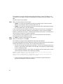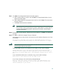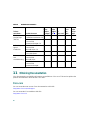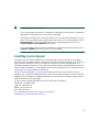
1
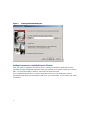
Quick Start
Quick Start
Quick Start Guide for Cisco Unified Service Monitor 2.0
1
2
3
4
5
6
7
8
9
10
11
12
13
14
15
16
SUPPLEMENTAL LICENSE AGREEMENT
Cisco Unified Service Monitor Overview
Server and Client System Requirements
Installation and Upgrade Paths
Installing Cisco Unified Service Monitor
Upgrading to Cisco Unified Service Monitor 2.0
Starting Cisco Unified Service Monitor
Uninstalling and Reinstalling Service Monitor
Where to Go Next
Related Documentation
Obtaining Documentation
Documentation Feedback
Cisco Product Security Overview
Product Alerts and Field Notices
Obtaining Technical Assistance
Obtaining Additional Publications and Information
1 SUPPLEMENTAL LICENSE AGREEMENT
SUPPLEMENTAL LICENSE AGREEMENT FOR CISCO SYSTEMS NETWORK MANAGEMENT
SOFTWARE: CISCO UNIFIED SERVICE MONITOR.
IMPORTANT-READ CAREFULLY: This Supplemental License Agreement (“SLA”) contains
additional limitations on the license to the Software provided to Customer under the End User License
Agreement between Customer and Cisco. Capitalized terms used in this SLA and not otherwise defined
herein shall have the meanings assigned to them in the End User License Agreement. To the extent that
there is a conflict among any of these terms and conditions applicable to the Software, the terms and
conditions in this SLA shall take precedence.
By installing, downloading, accessing or otherwise using the Software, Customer agrees to be bound
by the terms of this SLA. If Customer does not agree to the terms of this SLA, Customer may not
install, download or otherwise use the Software. When used below, the term “server” refers to central
processor unit.
1. ADDITIONAL LICENSE RESTRICTIONS.
• Installation and Use. The Software components are provided to Customer solely to install, update,
supplement, or replace existing functionality of the applicable Network Management Software
product. Customer may install and use the following Software components:
– CiscoWorks Common Services: Contains shared resources used by other components in this
bundle. In many cases, all components in this bundle can be installed on a single server.
– Cisco Unified Service Monitor: May be installed on one (1) server in Customer's network
management environment.
• Number of IP Phones. For each Software license granted, Customer may install and run the
Software on a single server to manage the number of IP phones specified in the license file provided
with the Software, or as specified in the Software License Claim Certificate. Customers whose
requirements exceed the IP phone limit must purchase upgrade licenses or additional copies of the
Software. The IP phone limit is enforced by license registration.
• Reproduction and Distribution. Customer may not reproduce nor distribute the Software.
2. DESCRIPTION OF OTHER RIGHTS AND LIMITATIONS.
Please refer to the Cisco Systems, Inc. End User License Agreement.
2
2 Cisco Unified Service Monitor Overview
Cisco Unified Service Monitor (Service Monitor), a product from the Cisco Unified Communications
Management Suite, receives and analyzes data from these sources when they are installed in your voice
network and configured properly:
• Cisco Unified CallManager clusters—Retain Call Detail Records (CDRs) and Call Management
Records (CMRs). CDRs include Mean Opinion Score (MOS) values that were calculated on IP
phones and voice gateways using the Cisco Voice Transmission Quality (CVTQ) algorithm.
Note
For Cisco Unified CallManager versions that Service Monitor supports, see Release Notes
for Cisco Unified Service Monitor 2.0. For information about configuring Cisco Unified
CallManager clusters to work with Service Monitor, see User Guide for Cisco Unified
Service Monitor.
• Cisco 1040 Sensors (sensors)—Compute MOS for each RTP stream; sensors sends syslog messages
to Service Monitor every 60 seconds.
Each licensed instance of Service Monitor can act as a primary Service Monitor for multiple
Cisco 1040s. If you have more than one licensed instance of Service Monitor, Service Monitor can
act as secondary backups for each other. Then, when a Service Monitor is unavailable,
Cisco 1040s can fail over to a secondary Service Monitor until the primary Service Monitor is once
again available.
Note
A Service Monitor that acts as a backup and the Service Monitor that it backs up must
both run the same version of Cisco Unified Service Monitor.
Service Monitor compares MOS against a threshold value—default or user-specified—for the codec in
use. When MOS drops below the threshold, Service Monitor generates SNMP traps and sends them to
up to four recipients. Service Monitor stores the data that it obtains in the database, where it is
available for display on Service Monitor reports. Service Monitor purges the database daily to
maintain 31 days of data. Optionally, Service Monitor also stores data obtained from Cisco 1040s in
files on disk.
If you configure Cisco Unified Operations Manager (Operations Manager) as a trap receiver for
Service Monitor, Operations Manager can further analyze, display, and act on the traps that Service
Monitor generates. Operations Manager can generate service quality events, display and track these
events on a real-time dashboard, and display and store event history. You can configure additional
event settings on Operations Manager that alert you to low MOS and to the occurrence of many
service quality events during a period of time. In addition, you can configure Operations Manager to
send notifications by e-mail, SNMP trap, and syslog message.
3
Licensing
Service Monitor features software-based product registration and license key activation technologies.
The following table provides information about terminology used in the registration process.
Understanding Licensing Terms
Table 1 describes the PAK and the License file and usage of these terms.
Table 1
Understanding PAK and License File
Licensing
Terms
Product
Authorization
Key (PAK)
Description
The PAK is printed on the software claim certificate included in product packaging.
Use the PAK and the MAC address of the server where Service Monitor 2.0 will
reside to get your license file from Cisco.com. The Service Monitor license file
includes support for up to 1,000 phones.
You can purchase incremental licenses to support additional IP phones, registering
up to 30,000 phones with a single Service Monitor. For each incremental license
that you purchase, a PAK is shipped to you, and you must use that PAK to obtain
a license file.
License file
When you use the PAK to register your product on the product licensing area of
Cisco.com, you will receive a license file. To register, you need to provide both of
the following:
• The MAC address of the server where Service Monitor 2.0 will reside.
• The PAK.
Licensing Your Product During Installation
Before you install the Service Monitor 2.0 product, you should register the product and obtain a
license file.
Note
4
If you are installing Service Monitor for evaluation only, you do not need to perform this
procedure.
To license your product, you must:
Step 1
Register the Service Monitor product with Cisco.com using the MAC address of the server on
which Cisco Unified Service Monitor 2.0 will reside and the PAK.
The PAK is printed on the software claim certificate. Get your license file from:
http://www.cisco.com/go/license
Note
You will be asked to log in. You must be a registered user of Cisco.com to log in.
Logging in allows your Cisco user profile information to autopopulate many of the product
registration fields. Login is case sensitive.
Step 2
Step 3
Copy the new license file to the Service Monitor server, into a directory with read permissions
for the user name casuser or the user group casusers.
Note
Service Monitor uses a local user, casuser, to run processes without having
Administrator privileges.
Note
If you copy a folder that contains the license file to the Service Monitor server, be sure
to provide read permission for casuser on the folder as well as on the license file.
Install the product using the Cisco Unified Service Monitor 2.0 product CD; during the
installation, when prompted for Licensing Information:
a. Select the first radio button (see Figure 1).
b. Use the browse window to locate the license file directory.
c. Click Next to install the license file.
Note
Add any incremental license files that you purchased to support additional IP phones after you
install or upgrade to Service Monitor 2.0. (See Adding Licenses to an Installed Service
Monitor, page 6.)
Figure 1 shows the licensing input dialog box that the installer displays during the installation process.
5
Figure 1
Licensing Information Dialog Box
Adding Licenses to an Installed Service Monitor
After you install or upgrade to Service Monitor 2.0, add any incremental licenses that you have
purchased to support additional IP phones. When you purchase an incremental license, you receive a
PAK. You must use the PAK to obtain a license file and install the license.
If you installed Service Monitor 2.0 with an evaluation license, you can subsequently install a
purchased license. When you purchase Service Monitor, you receive a PAK. Use it to obtain and install
a license file.
6
To add support for additional IP phones to Service Monitor and to upgrade from an evaluation license
to a purchased license, you must:
Step 1
Obtain the license file using the MAC address of the server where Service Monitor 2.0 is
installed and the PAK that you received when you purchased the product. Get your license file
from:
http://www.cisco.com/go/license
Note
You will be asked to log in. You must be a registered user of Cisco.com to log in.
Logging in allows your Cisco user profile information to autopopulate many of the product
registration fields. Login is case sensitive.
Step 2
Copy the new license file to the Service Monitor server, into a directory with read permissions
for the user name casuser or the user group casusers.
Note
Step 3
Service Monitor uses a local user, casuser, to run processes without having
Administrator privileges.
Install the license:
a. From Service Monitor, click the CiscoWorks link in the upper-right corner. The CiscoWorks
Homepage appears.
b. Select Common Services > Server > Admin > Licensing.
The License Administration page appears.
c. Click Update.
A file browser popup dialog box appears.
d. Enter the path to the new license file in the License field, or click Browse to locate the license
file you copied to the server in step 2.
e. Click OK.
The system verifies whether the license file is valid, and updates the license. The updated
licensing information appears on the License Information page. If you purchased more than
one license, repeat Step 3 to install each additional license.
If you encounter errors, repeat the steps to license your product.
7
3 Server and Client System Requirements
Table 2 lists minimum server requirements for Service Monitor. Table 3 lists minimum client
requirements for Service Monitor. Table 4 lists browser requirements for Service Monitor.
Note
The minimum server requirements in Table 2 might not be sufficient for monitoring a high
volume of calls. For more information, see Release Notes for
Cisco Unified Service Monitor 2.0.
Table 2
Minimum Server Requirements
Component
Hardware
Minimum Requirement
• Server platform with Pentium IV processor, 2.0 GHz or
greater
• Color monitor with video card capable of 256 colors or more
• CD-ROM drive
Software for Windows
Available memory (RAM)
Available disk space
Windows Server 2003 Service Pack 1, Standard and Enterprise
editions
Note
It is recommended that Service Monitor not share a
platform with other I/O or disk-intensive applications.
Note
Configure the server to use Network Time Protocol
(NTP) to synchronize with the time server that is used by
Cisco Unified CallManagers in your network. See NTP
Configuration Notes, page 10.
2 GB
• 60 GB minimum
• Virtual memory: 4 GB
• NTFS file system1 required.
1. Install Service Monitor on an NTFS file system. Do not install Service Monitor on a FAT file system. To verify the
file system, open My Computer on the Windows desktop, right-click the drive and select Properties from the popup
menu. The file system field appears in the General tab of the Properties dialog box.
8
Note
If you want to use a third-party SNMP management tool to make SNMP queries against the
server where Service Monitor is installed, Windows SNMP service must be installed. See
Configuring Your System for SNMP Queries, page 15.
Table 3
Minimum Client Hardware and Software Requirements
Component
Minimum Requirement
Hardware/software
• Any PC or server platform with a Pentium IV processor, 1.0 GHz or
greater, running one of the following:
– Windows 2000 (Professional and Server) with Service Pack 3 or
Service Pack 4
– Windows XP Service Pack 1 or Service Pack 2
– Windows 2003 Server (Standard and Enterprise Editions)
without Windows Terminal Services
• Color monitor with video card set to 256 colors
Available disk space
1 GB virtual memory
Available memory (RAM) 512 MB minimum
We recommend that you set virtual memory to twice the size of RAM.
Table 4
Browser Requirements
Browser
Version
Platform
Internet Explorer
6.0.28
Any one of the following:
• Windows 2000
• Windows XP
6.0 (6.0.3790.0)
Note
Windows Server 2003
When using Service Monitor, disable any software on your desktop that you use to prevent
popup windows from displaying. Service Monitor must be able to open multiple windows to
display information.
9
NTP Configuration Notes
The clocks on Service Monitor and Cisco Unified CallManager servers must be synchronized for
Service Monitor reports to include complete and up-to-date information and accurately reflect activity
during a given time period. These notes offer a starting point and do not provide complete instructions
for configuring NTP.
To get started:
1. Talk with your Cisco Unified CallManager administrators to determine the time server with which
Service Monitor should synchronize. You might find Cisco IP Telephony Clock Synchronization:
Best Practices, a white paper on Cisco.com, useful; read it at this URL:
http://cisco.com/en/US/products/sw/voicesw/ps556/prod_white_papers_list.html.
2. Use your system documentation to configure NTP on the Windows Server 2003 system where
Service Monitor will be installed. Configure NTP with the time server being used by
Cisco Unified CallManagers in your network. You might find How to configure an authoritative
time server in Windows Server 2003, useful; look for it at this URL:
http://support.microsoft.com/kb/816042.
Note
This website is Copyright © 2006, Microsoft Corporation.
Cisco Unified Service Monitor Port Usage
This section provides a list of ports used by Cisco Unified Service Monitor.
Note
Table 5
The ports in Table 5 should not be scanned.
Service Monitor Port Usage
Protocol Port Number
Service Name
UDP
53
DNS.
UDP
67 and 68
DHCP.
UDP
5666
Syslog—Service Monitor receives syslog messages from Cisco 1040.
TCP
22
SFTP—Service Monitor uses SFTP to obtain data from Cisco Unified
CallManager version 5.x.
TCP
2000
SCCP—Service Monitor uses SCCP to communicate with Cisco 1040s.
10
Table 5
Service Monitor Port Usage (continued)
Protocol Port Number
Service Name
TCP
43459
Database.
TCP
5665–5680
Interprocess communication between the user interface and back-end
processes.
Note
Note
These ports must be free.
Service Monitor uses TFTP to find the configuration file for a given Cisco 1040. Service
Monitor by default uses port 69 on the TFTP servers.
4 Installation and Upgrade Paths
Table 6 lists the supported installation paths. Table 7 lists the supported upgrade paths.
Table 6
Supported Installation Paths
If you are installing Cisco Unified
Service Monitor on a system that... Then do this
Service Monitor 2.0 is already installed. To activate
Has Operations Manager 2.0
Service Monitor 2.0:
(which includes
Service Monitor 2.0) installed and 1. Purchase Service Monitor 2.0 and obtain a PAK.
Service Monitor 2.0 is not yet
2. Use the PAK and the MAC address of the system where
licensed.
Operations Manager is installed to register your product on
Cisco.com and obtain a license file.
3. If you plan to add Cisco Unified CallManagers to Service
Monitor, configure the Service Monitor system to use NTP;
see NTP Configuration Notes, page 10.
4. Install the license file on the system where
Service Monitor 2.0 is installed. See Adding Licenses to an
Installed Service Monitor, page 6.
5. Perform the tasks in the configuration task checklist in User
Guide for Cisco Unified Service Monitor.
11
Table 6
Supported Installation Paths (continued)
If you are installing Cisco Unified
Service Monitor on a system that... Then do this
Has any product other than
Operations Manager 2.0 installed
1. Uninstall other products; for example, uninstall all
CiscoWorks and Network Management System (NMS)
products.
2. After you complete the uninstallation, verify that
NMSROOT, if it exists, does not contain any files.
NMSROOT is the directory where Service Monitor will be
installed; its default location is C:\Program Files\CSCOpx.
If NMSROOT exists, delete any files from it.
3. Use the instructions in this table for Does not have
Operations Manager 2.0 installed.
Does not have
Operations Manager 2.0 installed
1. If you want to manage Service Monitor using a third-party
SNMP management tool, install Windows SNMP service.
2. Use the PAK and the MAC address of the Service Monitor
server to register your product on Cisco.com and obtain a
license file.
3. Copy the license file to the server where you will install
Cisco Unified Service Monitor. See Licensing Your Product
During Installation, page 4.
4. If you plan to add Cisco Unified CallManagers to Service
Monitor, configure the Service Monitor system to use NTP;
see NTP Configuration Notes, page 10.
5. Install Cisco Unified Service Monitor 2.0.
6. Install any incremental license files that you purchased to
support additional IP phones. See Adding Licenses to an
Installed Service Monitor, page 6.
7. Perform the tasks in the configuration task checklist in User
Guide for Cisco Unified Service Monitor.
12
Table 7 lists the supported upgrade paths.
Table 7
Supported Upgrade Paths
If you are upgrading to
Cisco Unified Service Monitor 2.0
on a system that...
Then do this
Service Monitor software has already been upgraded. To
Has been upgraded with
activate Service Monitor 2.0:
Operations Manager 2.0 (which
includes Service Monitor 2.0) and 1. Order Service Monitor 2.0. The PAK will be shipped to you.
Service Monitor 2.0 is not yet
When you order, note that licensing for Service Monitor 2.0
licensed
no longer limits the number of sensors that can register.
Licensing is now based upon the number of phones being
monitored.
2. Use the PAK and the MAC address of the system where
Operations Manager is installed to register your product on
Cisco.com and obtain a license file.
3. If you plan to add Cisco Unified CallManagers to Service
Monitor, configure the Service Monitor system to use NTP;
see NTP Configuration Notes, page 10.
4. Delete any existing sensor configuration and binary image
files from your existing TFTP servers:
– Sensor configuration files include one
QOVDefault.CNF file and a QoVMACAddress.CNF
file for each sensor.
– The binary image file is SvcMonAA2_24.img.
5. Install the license file on the system where
Service Monitor 2.0 is installed. See Adding Licenses to an
Installed Service Monitor, page 6.
6. Complete the tasks listed in Performing Post-Upgrade
Configuration, page 24.
13
Table 7
Supported Upgrade Paths (continued)
If you are upgrading to
Cisco Unified Service Monitor 2.0
on a system that...
Has a licensed version of
Service Monitor 1.0 or
Service Monitor 1.1 installed
Then do this
1. Order Service Monitor 2.0. The PAK will be shipped to you.
When you order, note that licensing for Service Monitor 2.0
no longer limits the number of sensors that can register.
Licensing is now based upon the number of phones being
monitored.
2. Use the PAK and the MAC address of the server where
Service Monitor 1.0 or Service Monitor 1.1 is installed to
register your product on Cisco.com and obtain a license file.
3. If you plan to add Cisco Unified CallManagers to Service
Monitor, configure the Service Monitor system to use NTP;
see NTP Configuration Notes, page 10.
4. Delete any existing sensor configuration and binary image
files from your existing TFTP servers:
– Sensor configuration files include one
QOVDefault.CNF file and a QoVMACAddress.CNF
file for each sensor.
– The binary image file is SvcMonAA2_24.img.
5. Copy the license file to the server where Service Monitor 1.0
or 1.1 is installed. You will be prompted to supply the
license file location during the upgrade procedure.
6. Using the product CD, upgrade to Cisco Unified Service
Monitor 2.0. CiscoWorks Common Services 3.0 will also be
upgraded to Service Pack 4 (SP4).
7. Install any incremental license files that you have purchased
to support additional phones. See Adding Licenses to an
Installed Service Monitor, page 6.
8. Complete the tasks listed in Performing Post-Upgrade
Configuration, page 24.
14
5 Installing Cisco Unified Service Monitor
This section includes both of the following:
• Before You Install Service Monitor, page 15
• Performing the Service Monitor Installation, page 16
Before You Install Service Monitor
Service Monitor is already installed on a server when you install Operations Manager. To activate
Service Monitor on such a server, register your PAK on Cisco.com and install the license file for Cisco
Unified Service Monitor.
If you want to monitor Service Monitor using a third-party SNMP management tool, see Configuring
Your System for SNMP Queries, page 15.
To get ready for performing the installation, see Preparing Information that You Need to Install
Service Monitor, page 16.
Configuring Your System for SNMP Queries
Service Monitor implements the system application MIB. If you want to use a third-party SNMP
management tool to make SNMP queries against the server where Service Monitor is installed,
Windows SNMP service must be installed.
Note
To improve security, the SNMP set operation is not allowed on any object ID (OID) in the
system application MIB. After installation of Service Monitor, you should modify the
credentials for Windows SNMP service to not use a default or well-known community string.
You can install Windows SNMP service before or after you install Service Monitor. Use this procedure
to determine whether Windows SNMP service is installed.
Step 1
Verify that Windows SNMP service is installed on the server where you will install Service
Monitor. To do so:
a. Open the Windows administrative tool Services window.
b. Verify the following:
– SNMP Service is displayed on the Windows administrative tool Services window; if
so, Windows SNMP service is installed.
– SNMP service status is Started; if so, SNMP service is running.
Step 2
If Windows SNMP service is not installed, install it.
15
Note
Windows online help provides instructions for adding and removing Windows components,
such as Windows SNMP service. To locate the instructions, try selecting the Index tab in
Windows online help and entering a keyword or phrase, such as install SNMP service.
Preparing Information that You Need to Install Service Monitor
To install Service Monitor on a server without Operations Manager, you will need to supply the
following information during the installation:
• Licensing information—License file location. See Understanding Licensing Terms, page 4.
Note
If you are installing Service Monitor for evaluation purposes, you do not need to enter
licensing information.
• Passwords for the admin user and the system identity user—Passwords must contain at least 5
characters.
Note
The system identity user enables communication between servers through a trust model
and is used, for example, if you want to configure authentication and authorization for
Service Monitor using Cisco Secure ACS. For information about configuring
Service Monitor with ACS, see User Guide for Cisco Unified Service Monitor. For
information about the system identity account, see User Guide for
CiscoWorks Common Services 3.0.3.
Note
If you choose a Typical installation, the program generates passwords randomly for the
guest and casuser users, and for the database. If you choose a Custom installation, you
will be prompted for these passwords also.
Performing the Service Monitor Installation
Do not install Service Monitor on:
• A Primary Domain Controller (PDC) or Backup Domain Controller (BDC).
• A FAT file system.
16
• An Advanced Server with terminal services enabled in application server mode.
• A system with Internet Information Services (IIS) enabled.
• A system that does not have name lookup.
• A system with 2 network interface cards (NICs).
We recommend that you:
• Install Service Monitor on a system that has a static IP address.
• Disable the virus scan software on your system. You can restart it after installation is complete.
Before You Begin
Make sure your system meets the prerequisites:
• Required (or desired) operating system upgrades have been performed.
• Required Windows service packs are installed.
• Required minimum amount (or more) of RAM is available.
Close all open or active programs. Do not run other programs during the installation process.
Installing Service Monitor
Step 1
As the local administrator, log in to the machine on which you will install the Service Monitor
software, and insert the Service Monitor CD-ROM into the CD-ROM drive. The Cisco
Unified Service Monitor 2.0 Setup Program window opens.
If the CD-ROM is already in the CD-ROM drive and you stopped the installation process to
close programs or if Autostart is disabled, click Setup.exe to restart the process.
Step 2
Click Install. The Welcome window appears.
Step 3
Click Next. The Software License Agreement window appears.
Step 4
Click Accept. The Licensing Information window appears.
Step 5
Select one of the following, and then click Next:
• License File Location—Browse to enter the location. For instructions on obtaining a
license file, see Licensing, page 4.
• Evaluation Only—You can complete the upgrade and then register the license file later;
see Adding Licenses to an Installed Service Monitor, page 6.
Note
For instructions on obtaining a license file, see Licensing, page 4.
17
The installation program checks the name lookup and DHCP. If a static IP address is not
configured on your system, the DHCP-Enabled Network Adapters dialog box appears. Click
Yes.
The Setup Type window appears.
Step 6
Select one of the following radio buttons:
• Typical—To install the complete Service Monitor package, which contains Common
Services 3.0 with Service Pack 4 and Service Monitor 2.0.
• Custom—To install the complete Service Monitor package, select a destination directory,
and enter passwords for user and database.
If you choose the Typical installation mode, the following information will be supplied for
you for the Common Services installation: guest password, Common Services database
password, Web Server information, and self-signed certificate information. The remainder of
this procedure is written for a Typical installation.
If you choose the Custom installation mode, you will be prompted to enter the above
information during the installation process.
Step 7
Click Next. The Select Components window appears.
Step 8
Select all radio buttons. Click Next.
The installation program checks dependencies and system requirements.
The System Requirements window displays the results of the requirements check and advises
whether the installation can continue. One of the following might occur:
• If there is not enough disk space for the installation, or the correct operating system is not
present, or the minimum required RAM is not available, the installation program displays
an error message and stops.
• If your system has less than 4 GB of RAM, but meets the minimum requirement, you can
continue with the installation after reading this message:
WARNING: System memory is less than the requirement for Cisco Unified Service
Monitor system to support high call volume.
Please refer to Service Monitor documentation for more details and upgrade the
memory to at least 4GB if you have high call volume.
• If other minimum requirements are not met, the installation program displays an
appropriate message and continues installing.
18
Step 9
Click Next. The Change Admin Password window appears:
a. Enter an admin password, confirm, and click Next. The Change System Identity Account
Password window appears
b. Enter a System Identity Account password (and confirm), and click Next. The Create casuser
dialog box appears.
c. Click Yes to continue with the installation.
Note
If you selected the Custom installation mode, during this part of the installation you
will be asked to enter the following information: guest password, causer password,
Common Services database password, Web server information, and self-signed
certificate information.
Step 10 The Summary window appears, displaying the current settings. Click Next. The installation
proceeds.
Step 11 Click OK on additional messages if they are displayed:
If the system has more than one NIC and more than one IP address configured, you will see
this message:
This machine is multihomed. Please update the MULTI-HOME properties section in
C:\PROGRA~2\CSCOpx\lib\vbroker\gatekeeper.cfg after the installation is complete.
Caution
Do not run Service Monitor on this system; uninstall Service Monitor and install it on
another system that has only one NIC.
If Windows SNMP service is not installed on your system, you will see this message:
Windows SNMP service is not installed on your system. This installation will
continue. To install support for system application and host resources MIBs, you
must install the Windows SNMP service, using Add/Remove Programs from the Control
Panel.
If you installed Service Monitor for evaluation only, you will see this message:
Please obtain a valid license key from CCO within 90 days.
You will see a dialog box with the following message displayed:
Before you reboot this system, configure automatic time synchronization on it
using NTP. Configure this system to use the time server that is used by Cisco
Unified CallManagers in your network.
19
For more information, see NTP Configuration Notes, page 10.
Step 12 A message appears asking whether to reboot your system now. Reboot your system before you
start Step 13.
Step 13 After the installation completes, verify that Service Monitor was installed correctly by starting
Service Monitor. See Starting Cisco Unified Service Monitor, page 26.
After You Install Service Monitor
You should exclude the NMSROOT\databases directory from virus scanning. Problems can arise if
database files are locked because of virus scanning.
Note
NMSROOT is the directory where Service Monitor is installed on your system. If you selected
the default directory during installation, it is C:\Program Files\CSCOpx.
6 Upgrading to Cisco Unified Service Monitor 2.0
This section includes the following:
• Before You Upgrade to Service Monitor 2.0, page 20
• Performing the Upgrade to Service Monitor 2.0, page 21
• Performing Post-Upgrade Configuration, page 24
Before You Upgrade to Service Monitor 2.0
It is recommended that you delete existing sensor configuration and binary image files from your
existing TFTP servers before you perform the upgrade. Delete the following files:
• Sensor configuration files: One QOVDefault.CNF file and a QoVMACAddress.CNF file for each
sensor.
• Binary image file: SvcMonAA2_24.img.
You must perform post-upgrade configuration immediately after you upgrade to the Service Monitor
2.0 software, or the sensors will be unable to register to Service Monitor; for more information, see
Performing Post-Upgrade Configuration, page 24.
If you plan to add Cisco Unified CallManagers to Service Monitor, configure the server to use NTP
before you upgrade. For more information, see NTP Configuration Notes, page 10.
20
Note
In releases earlier than Service Monitor 2.0, licensing ensured that no more than the licensed
number of sensors was registered with Service Monitor. In Service Monitor 2.0, licensing
ensures that the licensed number of phones being monitored is not greatly exceeded.
Service Monitor software is already upgraded to release 2.0 on a server where you have upgraded to
Operations Manager 2.0. To activate Service Monitor on such a server:
1. Delete existing sensor configuration files (QOV*.CNF) and binary image files (SvcMon*.img)
from your TFTP servers.
2. Register your PAK on Cisco.com and install the license file for Cisco Unified Service Monitor.
3. Complete the tasks in Performing Post-Upgrade Configuration, page 24.
Performing the Upgrade to Service Monitor 2.0
Note
Immediately after you upgrade, sensors are unable register to Service Monitor until you
complete the tasks listed in Performing Post-Upgrade Configuration, page 24.
As a precaution, the upgrade procedure performs a backup prior to copying and installing new files
on your system.
Step 1
As the local administrator, log in to the machine on which Service Monitor 1.0 or Service
Monitor 1.1 is installed, and insert the Service Monitor 2.0 CD-ROM into the CD-ROM
drive. The Cisco Unified Service Monitor 2.0 Setup Program window opens.
If the CD-ROM is already in the CD-ROM drive and you stopped the installation process to
close programs or if Autostart is disabled, click Setup.exe to restart the process.
Step 2
Click Install. The Welcome window appears.
Step 3
Click Next. The Software License Agreement window appears.
Step 4
Click Accept. The installation program checks the name lookup and DHCP.
If a static IP address is not configured on your system, the DHCP-Enabled Network Adapters
dialog box appears. Click Yes.
The Setup Type window appears.
21
Step 5
Select one of the following radio buttons:
• Typical—To install the complete Service Monitor package, which contains Common
Services 3.0 with Service Pack 4 and Service Monitor 2.0.
• Custom—To install the complete Service Monitor package and to enter data that is
otherwise entered automatically for you.
If you choose the Typical installation mode, the following information will be supplied for
you for the Common Services installation: guest password, Common Services database
password, Web Server information, and self-signed certificate information.
If you choose the Custom installation mode, you will be prompted to enter the above
information during the installation process.
Step 6
Click Next. The Backup Data window appears.
Step 7
Enter or browse to a directory where you want to store data and click Next. The backup starts
and a message is displayed while it is in progress. The Select Components window appears.
Step 8
Select all radio buttons and click Next. The installation program checks dependencies and
system requirements. The System Requirements window displays the results of the
requirements check and advises whether the installation can continue. One of the following
might occur:
• If there is not enough disk space for the installation or the minimum required RAM is not
available, the installation program displays an error message and stops.
• If your system has less than 4 GB of RAM, but meets the minimum requirement, you can
continue with the installation after reading this message:
WARNING: System memory is less than the requirement for Cisco Unified Service
Monitor system to support high call volume.
Please refer to Service Monitor documentation for more details and upgrade the
memory to at least 4GB if you have high call volume.
• If other minimum requirements are not met, the installation program displays an
appropriate message and continues installing.
Step 9
The Summary window appears, displaying the current settings. Click Next. The upgrade
proceeds and completes.
Step 10 Click OK on additional messages if they are displayed:
If the system has more than one NIC and more than one IP address configured, you will see
this message:
This machine is multihomed. Please update the MULTI-HOME properties section in
C:\PROGRA~2\CSCOpx\lib\vbroker\gatekeeper.cfg after the installation is complete.
22
Caution
Do not run Service Monitor on this system; uninstall Service Monitor and install it on
another system that has only one NIC.
If Windows SNMP service is not installed on your system, you will see this message:
Windows SNMP service is not installed on your system. This installation will
continue. To install support for system application and host resources MIBs, you
must install the Windows SNMP service, using Add/Remove Programs from the Control
Panel.
Step 11 From Windows Explorer, delete any files in the folder NMSROOT\MDC\tomcat\work.
Note
Delete files, but not folders within NMSROOT\MDC\tomcat\work. NMSROOT is
the directory where Service Monitor is installed. Its default location is
C:\Program Files\CSCOpx.
Step 12 A dialog box with the following message is displayed:
Before you reboot this system, configure automatic time synchronization on it
using NTP. Configure this system to use the time server that is used by Cisco
Unified CallManagers in your network.
Click OK. (For more information, see NTP Configuration Notes, page 10.)
Step 13 A message is displayed asking whether to reboot the server. Reboot your system before you
start Step 14.
Step 14 After you reboot the server, verify the upgrade by starting Service Monitor. See Starting Cisco
Unified Service Monitor, page 26.
Note
After upgrade, logging settings are returned to their default values. As a result, only error
messages are written to Service Monitor log files. If you need additional information in
your log files to help you debug a problem, update your logging settings. See the
Service Monitor online help for instructions.
Step 15 Complete the tasks listed in Performing Post-Upgrade Configuration, page 24. Sensors will
not register to Service Monitor until you complete this step.
23
Performing Post-Upgrade Configuration
This section provides the minimum steps required to enable sensors to register with
Service Monitor 2.0. For complete configuration procedures, including how to add Cisco Unified
CallManagers to Service Monitor, see the configuration checklists in User Guide for Cisco Unified
Service Monitor.
Step 1
Start Service Monitor. See Starting Cisco Unified Service Monitor, page 26.
Step 2
Add at least one TFTP server to Service Monitor:
a. Select Configuration > Sensor > TFTP Servers. The TFTP Server Setup page appears.
b. Click Add. The TFTP Server Settings dialog box appears.
c. Enter data in the following fields:
– TFTP Server—IP address or DNS name.
– Port Number—The default port number is 69.
d. Click OK.
Note
If you want to use a Cisco Unified CallManager 5.x or 4.2 as a TFTP server, you can do so.
Step 3
Configure the default configuration file:
a. Select Configuration > Sensor > Setup. The Setup page appears.
b. Update the Default Configuration to TFTP Server fields:
– Image Filename—Enter SvcMonAA2_34.img.
– Primary Service Monitor—Enter an IP address or DNS name.
– Secondary Service Monitor—(Optional) Enter an IP address or DNS name.
c. Click OK. Service Monitor stores the default configuration file locally and copies it to the
TFTP servers that you added in Step 2.
d. Copy the binary image file, SvcMonAA2_34.img, from NMSROOT\ImageDir on the Service
Monitor server to the root location on the TFTP server. (NMSROOT is the directory where
Service Monitor is installed; its default location is C:\Program Files\CSCOpx.)
e. Verify that the newly created QOVDefault.CNF file is on the TFTP server. If it is not, upload
it to the root location on the TFTP server from the Service Monitor image file directory,
NMSROOT\ImageDir. For examples of the configuration files, see Sample Sensor
Configuration Files, page 25.
24
Note
If you use Cisco Unified CallManager as a TFTP server, Service Monitor cannot copy
configuration files to Cisco Unified CallManager due to security settings on the latter. You will
need to manually upload the configuration file as described in Step 3e. After uploading the
configuration file, reset the TFTP server on Cisco Unified CallManager. For more information,
see Cisco Unified CallManager documentation.
Step 4
Wait a few minutes and verify that sensors have registered to Service Monitor. If they have
not, reset the sensors by disconnecting them from power and connecting them again.
Warning
Before disconnecting a sensor, read the regulatory compliance and safety information in
Quick Start Guide for Cisco 1040 Sensor.
Sample Sensor Configuration Files
Service Monitor creates these files when you edit the configuration through the user interface and when
a sensor uses the default configuration file to register. These samples are provided to enable you to
confirm that the contents of a sensor configuration file are correct.
Note
Always use the Service Monitor user interface to edit sensor configuration files to ensure that
Service Monitor functions properly. Do not edit sensor configuration files on the TFTP server.
Default Configuration File—QOVDefault.CNF
In the default configuration file, the ID, A000, is a placeholder; an IP address or alternatively a DNS
name is provided for the Receiver. The last updated data and time represent the last time that the
default configuration was updated from the Service Monitor user interface.
Receiver=10.92.99.22;;
ID=A000
Image=SvcMonAA2_34.img
LastUpdated=11_16_2006-6_59_46.78
CDPGlobalRunState=true
SyslogPort=UDP:5666
SkinnyPort=TCP:2000
25
MAC-Specific Configuration File—QOV001120FFCF18.CNF
In a MAC-specific configuration file, the default ID, A000, has been replaced by the sensor MAC
address; the receiver DNS name is included, although an IP address could appear instead. The last
updated date and time represent the last time that the configuration file was updated; this could be
when the sensor registered with Service Monitor or when a user edited the configuration file from the
Service Monitor user interface.
Receiver=qovr-weekly;;
ID=001120FFCF18
Image=SvcMonAA2_34.img
LastUpdated=11_13_2006-4_3_57.578
CDPGlobalRunState=true
SyslogPort=UDP:5666
SkinnyPort=TCP:2000
7 Starting Cisco Unified Service Monitor
Step 1
In your browser, type http://servername:1741 where servername is the IP address or DNS
name of the server where Service Monitor resides. A login page is displayed.
Step 2
Enter a username and password. If you do not have a username, you can do the following:
• Enter admin for the user ID.
• Enter the password that you entered for the admin user during installation and press
Enter.
The Service Monitor home page appears.
8 Uninstalling and Reinstalling Service Monitor
This section contains the following:
• Uninstalling Service Monitor
• Reinstalling Service Monitor
26
Uninstalling Service Monitor
Caution
You must use the Cisco Unified Service Monitor uninstallation program to remove
Service Monitor from your system. If you try to remove the files and programs manually,
you can seriously damage your system.
Use this procedure if you need to uninstall Service Monitor.
Step 1
As the local administrator, log in to the system on which Service Monitor is installed, and
select Start > All Programs > Cisco Unified Service Monitor 2.0 > Uninstall Cisco Unified
Service Monitor 2.0 to start the uninstallation process. A window appears, listing the
components available for uninstallation.
Step 2
Select all check boxes. Click Next. A window appears, displaying the components you have
selected to uninstall.
Step 3
Click Next.
Messages showing the progress of the uninstallation appear. The Uninstallation Complete
dialog box displays this message:
Before you install Service Monitor product, you must restart your computer.
Step 4
Click OK and restart your system.
Step 5
Delete any files that remain in the NMSROOT directory. NMSROOT is the directory where
Service Monitor was installed; its default location is C:\Program Files\CSCOpx.
Reinstalling Service Monitor
The existing database is preserved when you reinstall Service Monitor. As a precaution, the
reinstallation procedure performs a backup prior to copying and installing new files on your system.
Note
To reinstall Service Monitor on a system with Operations Manager, you must reinstall both
Operations Manager and Service Monitor; see Installation Guide for Cisco Unified
Operations Manager (Includes Service Monitor).
Use this procedure if you need to install Service Monitor 2.0 on a system where Service Monitor 2.0
is already installed.
27
Step 1
As the local administrator, log in to the machine on which you will reinstall Service Monitor,
and insert the Service Monitor CD-ROM into the CD-ROM drive. The installer window
appears, asking you if you want to install Service Monitor.
Note
If the CD-ROM is already in the CD-ROM drive and you stopped the reinstallation
process to close programs or if Autostart is disabled, click Setup.exe from the top
directory of your CD-ROM to restart the process.
Step 2
Click Yes. The Welcome window appears.
Step 3
Click Next. The Software License Agreement window appears.
Step 4
Click Accept. The installation program checks the name lookup and DHCP.
If a static IP address is not configured on your system, the DHCP-Enabled Network Adapters
dialog box appears. Click Yes.
The Setup Type dialog box appears.
Step 5
Select the Typical radio button and click Next. The Backup Data window appears.
Step 6
Enter or browse to a directory where you want to store data and click Next. The backup starts
and a message is displayed while it is in progress. The Select Components window appears.
Step 7
Select all radio buttons. Click Next.
The installation program checks dependencies and system requirements.
The System Requirements window displays the results of the requirements check and advises
whether the installation can continue. One of the following might occur:
• If there is not enough disk space for the installation, the installation program displays an
error message and stops.
• If your system has less than 4 GB of RAM, but meets the minimum requirement, you can
continue with the installation after reading this message:
WARNING: System memory is less than the requirement for Cisco Unified Service
Monitor system to support high call volume.
Please refer to Service Monitor documentation for more details and upgrade the
memory to at least 4GB if you have high call volume.
• If other minimum requirements are not met, the installation program displays an
appropriate message and continues installing.
Step 8
Click Next. A message is displayed, informing you that this is a reinstallation and that the
database will be preserved.
Step 9
Click OK.
28
Step 10 The Summary window appears, displaying the current settings. Click Next. The reinstallation
proceeds and the Setup Complete window appears.
Step 11 Click Finish.
9 Where to Go Next
After you have installed Service Monitor, you are ready to configure it and start monitoring
IP telephony service quality. For more information, see the following User Guides:
• User Guide for Cisco Unified Service Monitor
• User Guide for Cisco Unified Operations Manager
You can access these documents:
• In PDF format, in the Documentation directory on the respective product CD-ROM.
• From the online help integrated into the product.
Note
For information about Cisco 1040 Sensor, see Quick Start Guide for Cisco 1040 Sensor,
shipped with Cisco 1040 and available on Cisco.com.
10 Related Documentation
Note
The originally published printed and electronic documentation is included with your product.
Any changes after original publication are reflected on Cisco.com, where you will find the
most up-to-date documentation.
For information about installing, troubleshooting, and using the applications and tools in the Cisco
Unified Communications Management Suite, see the sources of information described in Table 8.
Note
To view documents in Adobe Portable Document Format (PDF), Adobe Acrobat 4.0 or later
is required.
29
Table 8
Related Documentation
To learn
more about...
See this document
On the
In the
On the
Cisco
product
product On
Doc.
package? CD?1
Cisco.com? DVD?
In the
online
help?
The known
product bugs
(DDTSs)
Release Notes for Cisco
No
Unified Service Monitor 2.0
Yes
Yes
Yes
No
Release Notes for
Cisco Unified
Operations Manager 2.0
No
No
Yes
Yes
No
Performing a
typical
installation
Quick Start Guide for
Cisco Unified
Service Monitor 2.0
Yes
Yes
Yes
Yes
No
Quick Start Guide for
Cisco 1040 Sensor
No
Yes
Yes
Yes
No
User Guide for
Cisco Unified
Service Monitor
No
Yes
Yes
Yes
Yes
User Guide for
Cisco Unified
Operations Manager
No
No
Yes
Yes
No
Features, tasks,
and
troubleshooting
1. Provided in PDF format, in the Documentation folder on the product CD.
11 Obtaining Documentation
Cisco documentation and additional literature are available on Cisco.com. This section explains the
product documentation resources that Cisco offers.
Cisco.com
You can access the most current Cisco documentation at this URL:
http://www.cisco.com/techsupport
You can access the Cisco website at this URL:
http://www.cisco.com
30
You can access international Cisco websites at this URL:
http://www.cisco.com/public/countries_languages.shtml
Product Documentation DVD
The Product Documentation DVD is a library of technical product documentation on a portable
medium. The DVD enables you to access installation, configuration, and command guides for Cisco
hardware and software products. With the DVD, you have access to the HTML documentation and
some of the PDF files found on the Cisco website at this URL:
http://www.cisco.com/univercd/home/home.htm
The Product Documentation DVD is created and released regularly. DVDs are available singly or by
subscription. Registered Cisco.com users can order a Product Documentation DVD (product number
DOC-DOCDVD= or DOC-DOCDVD=SUB) from Cisco Marketplace at the Product Documentation
Store at this URL:
http://www.cisco.com/go/marketplace/docstore
Ordering Documentation
You must be a registered Cisco.com user to access Cisco Marketplace. Registered users may order
Cisco documentation at the Product Documentation Store at this URL:
http://www.cisco.com/go/marketplace/docstore
If you do not have a user ID or password, you can register at this URL:
http://tools.cisco.com/RPF/register/register.do
12 Documentation Feedback
You can provide feedback about Cisco technical documentation on the Cisco Support site area by
entering your comments in the feedback form available in every online document.
13 Cisco Product Security Overview
Cisco provides a free online Security Vulnerability Policy portal at this URL:
http://www.cisco.com/en/US/products/products_security_vulnerability_policy.html
31
From this site, you will find information about how to do the following:
• Report security vulnerabilities in Cisco products
• Obtain assistance with security incidents that involve Cisco products
• Register to receive security information from Cisco
A current list of security advisories, security notices, and security responses for Cisco products is
available at this URL:
http://www.cisco.com/go/psirt
To see security advisories, security notices, and security responses as they are updated in real time, you
can subscribe to the Product Security Incident Response Team Really Simple Syndication (PSIRT RSS)
feed. Information about how to subscribe to the PSIRT RSS feed is found at this URL:
http://www.cisco.com/en/US/products/products_psirt_rss_feed.html
Reporting Security Problems in Cisco Products
Cisco is committed to delivering secure products. We test our products internally before we release
them, and we strive to correct all vulnerabilities quickly. If you think that you have identified a
vulnerability in a Cisco product, contact PSIRT:
• For emergencies only — [email protected]
An emergency is either a condition in which a system is under active attack or a condition for
which a severe and urgent security vulnerability should be reported. All other conditions are
considered nonemergencies.
• For nonemergencies — [email protected]
In an emergency, you can also reach PSIRT by telephone:
• 1 877 228-7302
• 1 408 525-6532
32
Tip
We encourage you to use Pretty Good Privacy (PGP) or a compatible product (for example,
GnuPG) to encrypt any sensitive information that you send to Cisco. PSIRT can work with
information that has been encrypted with PGP versions 2.x through 9.x.
Never use a revoked encryption key or an expired encryption key. The correct public key to
use in your correspondence with PSIRT is the one linked in the Contact Summary section of
the Security Vulnerability Policy page at this URL:
http://www.cisco.com/en/US/products/products_security_vulnerability_policy.html
The link on this page has the current PGP key ID in use.
If you do not have or use PGP, contact PSIRT to find other means of encrypting the data before
sending any sensitive material.
14 Product Alerts and Field Notices
Modifications to or updates about Cisco products are announced in Cisco Product Alerts and
Cisco Field Notices. You can receive these announcements by using the Product Alert Tool on
Cisco.com. This tool enables you to create a profile and choose those products for which you want
to receive information.
To access the Product Alert Tool, you must be a registered Cisco.com user. Registered users can access
the tool at this URL:
http://tools.cisco.com/Support/PAT/do/ViewMyProfiles.do?local=en
To register as a Cisco.com user, go to this URL:
http://tools.cisco.com/RPF/register/register.do
15 Obtaining Technical Assistance
Cisco Technical Support provides 24-hour-a-day award-winning technical assistance. The
Cisco Support website on Cisco.com features extensive online support resources. In addition, if
you have a valid Cisco service contract, Cisco Technical Assistance Center (TAC) engineers provide
telephone support. If you do not have a valid Cisco service contract, contact your reseller.
33
Cisco Support Website
The Cisco Support website provides online documents and tools for troubleshooting and resolving
technical issues with Cisco products and technologies. The website is available 24 hours a day at
this URL:
http://www.cisco.com/en/US/support/index.html
Access to all tools on the Cisco Support website requires a Cisco.com user ID and password. If you
have a valid service contract but do not have a user ID or password, you can register at this URL:
http://tools.cisco.com/RPF/register/register.do
Note
34
Before you submit a request for service online or by phone, use the Cisco Product
Identification Tool to locate your product serial number. You can access this tool from the
Cisco Support website by clicking the Get Tools & Resources link, clicking the All Tools
(A-Z) tab, and then choosing Cisco Product Identification Tool from the alphabetical list.
This tool offers three search options: by product ID or model name; by tree view; or, for
certain products, by copying and pasting show command output. Search results show an
illustration of your product with the serial number label location highlighted. Locate the serial
number label on your product and record the information before placing a service call.
Tip
Displaying and Searching on Cisco.com
If you suspect that the browser is not refreshing a web page, force the browser to update the
web page by holding down the Ctrl key while pressing F5.
To find technical information, narrow your search to look in technical documentation, not the
entire Cisco.com website. After using the Search box on the Cisco.com home page, click the
Advanced Search link next to the Search box on the resulting page and then click the
Technical Support & Documentation radio button.
To provide feedback about the Cisco.com website or a particular technical document, click
Contacts & Feedback at the top of any Cisco.com web page.
Submitting a Service Request
Using the online TAC Service Request Tool is the fastest way to open S3 and S4 service requests.
(S3 and S4 service requests are those in which your network is minimally impaired or for which you
require product information.) After you describe your situation, the TAC Service Request Tool
provides recommended solutions. If your issue is not resolved using the recommended resources, your
service request is assigned to a Cisco engineer. The TAC Service Request Tool is located at this URL:
http://www.cisco.com/techsupport/servicerequest
For S1 or S2 service requests, or if you do not have Internet access, contact the Cisco TAC by
telephone. (S1 or S2 service requests are those in which your production network is down or severely
degraded.) Cisco engineers are assigned immediately to S1 and S2 service requests to help keep your
business operations running smoothly.
To open a service request by telephone, use one of the following numbers:
Asia-Pacific: +61 2 8446 7411
Australia: 1 800 805 227
EMEA: +32 2 704 55 55
USA: 1 800 553 2447
For a complete list of Cisco TAC contacts, go to this URL:
http://www.cisco.com/techsupport/contacts
35
Definitions of Service Request Severity
To ensure that all service requests are reported in a standard format, Cisco has established severity
definitions.
Severity 1 (S1)—An existing network is “down” or there is a critical impact to your business
operations. You and Cisco will commit all necessary resources around the clock to resolve the
situation.
Severity 2 (S2)—Operation of an existing network is severely degraded, or significant aspects of your
business operations are negatively affected by inadequate performance of Cisco products. You and
Cisco will commit full-time resources during normal business hours to resolve the situation.
Severity 3 (S3)—Operational performance of the network is impaired while most business operations
remain functional. You and Cisco will commit resources during normal business hours to restore
service to satisfactory levels.
Severity 4 (S4)—You require information or assistance with Cisco product capabilities, installation, or
configuration. There is little or no effect on your business operations.
16 Obtaining Additional Publications and Information
Information about Cisco products, technologies, and network solutions is available from various
online and printed sources.
• The Cisco Online Subscription Center is the website where you can sign up for a variety of Cisco
e-mail newsletters and other communications. Create a profile and then select the subscriptions
that you would like to receive. To visit the Cisco Online Subscription Center, go to this URL:
http://www.cisco.com/offer/subscribe
• The Cisco Product Quick Reference Guide is a handy, compact reference tool that includes brief
product overviews, key features, sample part numbers, and abbreviated technical specifications
for many Cisco products that are sold through channel partners. It is updated twice a year and
includes the latest Cisco channel product offerings. To order and find out more about the
Cisco Product Quick Reference Guide, go to this URL:
http://www.cisco.com/go/guide
• Cisco Marketplace provides a variety of Cisco books, reference guides, documentation, and logo
merchandise. Visit Cisco Marketplace, the company store, at this URL:
http://www.cisco.com/go/marketplace/
• Cisco Press publishes a wide range of general networking, training, and certification titles. Both
new and experienced users will benefit from these publications. For current Cisco Press titles and
other information, go to Cisco Press at this URL:
http://www.ciscopress.com
36
• Internet Protocol Journal is a quarterly journal published by Cisco for engineering professionals
involved in designing, developing, and operating public and private internets and intranets. You
can access the Internet Protocol Journal at this URL:
http://www.cisco.com/ipj
• Networking products offered by Cisco, as well as customer support services, can be obtained at
this URL:
http://www.cisco.com/en/US/products/index.html
• Networking Professionals Connection is an interactive website where networking professionals
share questions, suggestions, and information about networking products and technologies with
Cisco experts and other networking professionals. Join a discussion at this URL:
http://www.cisco.com/discuss/networking
• “What’s New in Cisco Documentation” is an online publication that provides information about
the latest documentation releases for Cisco products. Updated monthly, this online publication is
organized by product category to direct you quickly to the documentation for your products. You
can view the latest release of “What’s New in Cisco Documentation” at this URL:
http://www.cisco.com/univercd/cc/td/doc/abtunicd/136957.htm
• World-class networking training is available from Cisco. You can view current offerings at
this URL:
http://www.cisco.com/en/US/learning/index.html
37
38
39
Corporate Headquarters
Cisco Systems, Inc.
170 West Tasman Drive
San Jose, CA 95134-1706
USA
www.cisco.com
Tel: 408 526-4000
800 553-NETS (6387)
Fax: 408 526-4100
European Headquarters
Cisco Systems International BV
Haarlerbergpark
Haarlerbergweg 13-19
1101 CH Amsterdam
The Netherlands
www-europe.cisco.com
Tel: 31 0 20 357 1000
Fax: 31 0 20 357 1100
Americas Headquarters
Cisco Systems, Inc.
170 West Tasman Drive
San Jose, CA 95134-1706
USA
www.cisco.com
Tel: 408 526-7660
Fax: 408 527-0883
Asia Pacific Headquarters
Cisco Systems, Inc.
168 Robinson Road
#28-01 Capital Tower
Singapore 068912
www.cisco.com
Tel: +65 6317 7777
Fax: +65 6317 7799
Cisco Systems has more than 200 offices in the following countries. Addresses, phone numbers, and fax numbers are listed on the
Cisco Website at www.cisco.com/go/offices
Argentina • Australia • Austria • Belgium • Brazil • Bulgaria • Canada • Chile • China PRC • Colombia • Costa Rica • Croatia • Cyprus • Czech Republic • Denmark • Dubai, UAE
Finland • France • Germany • Greece • Hong Kong SAR • Hungary • India • Indonesia • Ireland • Israel • Italy • Japan • Korea • Luxembourg • Malaysia • Mexico
The Netherlands • New Zealand • Norway • Peru • Philippines • Poland • Portugal • Puerto Rico • Romania • Russia • Saudi Arabia • Scotland • Singapore
Slovakia • Slovenia • South Africa • Spain • Sweden • Switzerland • Taiwan • Thailand • Turkey • Ukraine • United Kingdom • United States • Venezuela • Vietnam • Zimbabwe
CCVP, the Cisco Logo, and the Cisco Square Bridge logo are trademarks of Cisco Systems, Inc.; Changing the Way We Work, Live, Play, and Learn is a service mark of Cisco Systems,
Inc.; and Access Registrar, Aironet, BPX, Catalyst, CCDA, CCDP, CCIE, CCIP, CCNA, CCNP, CCSP, Cisco, the Cisco Certified Internetwork Expet logo, Cisco IOS, Cisco Press,
Cisco Systems, Cisco Systems Capital, the Cisco Systems logo, Cisco Unity, Enterprise/Solver, EtherChannel, EtherFast, EtherSwitch, Fast Step, Follow Me Browsing, FormShare,
GigaDrive, GigaStack, HomeLink, Internet Quotient, IOS, iPhone, IP/TV, iQ Expertise, the iQ logo, iQ Net Readiness Scorecard, iQuick Study, LightStream, Linksys, MeetingPlace,
MGX, Networking Academy, Network Registrar, Packet, PIX, ProConnect, RateMUX, ScriptShare, SlideCast, SMARTnet, StackWise, The Fastest Way to Increase Your Internet
Quotient, and TransPath are registered trademarks of Cisco Systems, Inc. and/or its affiliates in the United States and certain other countries.
All other trademarks mentioned in this document or Website are the property of their respective owners. The use of the word partner does not imply a partnership relationship
between Cisco and any other company. (0612R)
© 2005-2006 Cisco Systems, Inc. All rights reserved.
Printed in the USA on recycled paper containing 10% postconsumer waste.
78-17675-02