1
User Guide for Cisco Secure Access
Control System 5.4
November 2013
Americas Headquarters
Cisco Systems, Inc.
170 West Tasman Drive
San Jose, CA 95134-1706
USA
http://www.cisco.com
Tel: 408 526-4000
800 553-NETS (6387)
Fax: 408 527-0883
Text Part Number: OL-26225-01
THE SPECIFICATIONS AND INFORMATION REGARDING THE PRODUCTS IN THIS MANUAL ARE SUBJECT TO CHANGE WITHOUT NOTICE. ALL
STATEMENTS, INFORMATION, AND RECOMMENDATIONS IN THIS MANUAL ARE BELIEVED TO BE ACCURATE BUT ARE PRESENTED WITHOUT
WARRANTY OF ANY KIND, EXPRESS OR IMPLIED. USERS MUST TAKE FULL RESPONSIBILITY FOR THEIR APPLICATION OF ANY PRODUCTS.
THE SOFTWARE LICENSE AND LIMITED WARRANTY FOR THE ACCOMPANYING PRODUCT ARE SET FORTH IN THE INFORMATION PACKET THAT
SHIPPED WITH THE PRODUCT AND ARE INCORPORATED HEREIN BY THIS REFERENCE. IF YOU ARE UNABLE TO LOCATE THE SOFTWARE LICENSE
OR LIMITED WARRANTY, CONTACT YOUR CISCO REPRESENTATIVE FOR A COPY.
The Cisco implementation of TCP header compression is an adaptation of a program developed by the University of California, Berkeley (UCB) as part of UCB’s public
domain version of the UNIX operating system. All rights reserved. Copyright © 1981, Regents of the University of California.
NOTWITHSTANDING ANY OTHER WARRANTY HEREIN, ALL DOCUMENT FILES AND SOFTWARE OF THESE SUPPLIERS ARE PROVIDED “AS IS” WITH
ALL FAULTS. CISCO AND THE ABOVE-NAMED SUPPLIERS DISCLAIM ALL WARRANTIES, EXPRESSED OR IMPLIED, INCLUDING, WITHOUT
LIMITATION, THOSE OF MERCHANTABILITY, FITNESS FOR A PARTICULAR PURPOSE AND NONINFRINGEMENT OR ARISING FROM A COURSE OF
DEALING, USAGE, OR TRADE PRACTICE.
IN NO EVENT SHALL CISCO OR ITS SUPPLIERS BE LIABLE FOR ANY INDIRECT, SPECIAL, CONSEQUENTIAL, OR INCIDENTAL DAMAGES, INCLUDING,
WITHOUT LIMITATION, LOST PROFITS OR LOSS OR DAMAGE TO DATA ARISING OUT OF THE USE OR INABILITY TO USE THIS MANUAL, EVEN IF CISCO
OR ITS SUPPLIERS HAVE BEEN ADVISED OF THE POSSIBILITY OF SUCH DAMAGES.
Cisco and the Cisco logo are trademarks or registered trademarks of Cisco and/or its affiliates in the U.S. and other countries. To view a list of Cisco trademarks, go to this
URL: www.cisco.com/go/trademarks. Third-party trademarks mentioned are the property of their respective owners. The use of the word partner does not imply a partnership
relationship between Cisco and any other company. (1110R)
Any Internet Protocol (IP) addresses used in this document are not intended to be actual addresses. Any examples, command display output, and figures included in the
document are shown for illustrative purposes only. Any use of actual IP addresses in illustrative content is unintentional and coincidental.
User Guide for Cisco Secure Access Control System 5.4
© 2012 Cisco Systems, Inc. All rights reserved.
C O N T E N T S
Preface
xxiii
Audience
xxiii
Document Conventions
xxiii
Documentation Updates
xxiv
Related Documentation
xxiv
Obtaining Documentation and Submitting a Service Request
CHAPTER
1
Introducing ACS 5.4
1-1
Overview of ACS
1-1
xxv
ACS Distributed Deployment 1-2
ACS 4.x and 5.4 Replication 1-2
ACS Licensing Model
1-3
ACS Management Interfaces 1-3
ACS Web-based Interface 1-4
ACS Command Line Interface 1-4
ACS Programmatic Interfaces 1-5
Hardware Models Supported by ACS
CHAPTER
2
Migrating from ACS 4.x to ACS 5.4
Overview of the Migration Process
Migration Requirements 2-2
Supported Migration Versions
Before You Begin
1-5
2-1
2-2
2-2
2-3
Downloading Migration Files
2-3
Migrating from ACS 4.x to ACS 5.4
2-3
Functionality Mapping from ACS 4.x to ACS 5.4
2-5
Common Scenarios in Migration 2-7
Migrating from ACS 4.2 on CSACS 1120 to ACS 5.4
Migrating from ACS 3.x to ACS 5.4 2-8
Migrating Data from Other AAA Servers to ACS 5.4
CHAPTER
3
ACS 5.x Policy Model
2-7
2-8
3-1
Overview of the ACS 5.x Policy Model
3-1
User Guide for Cisco Secure Access Control System 5.4
OL-26225-01
iii
Contents
Policy Terminology 3-3
Simple Policies 3-4
Rule-Based Policies 3-4
Types of Policies 3-5
Access Services 3-6
Identity Policy 3-9
Group Mapping Policy 3-11
Authorization Policy for Device Administration 3-11
Processing Rules with Multiple Command Sets 3-11
Exception Authorization Policy Rules 3-12
Service Selection Policy 3-12
Simple Service Selection 3-12
Rules-Based Service Selection 3-13
Access Services and Service Selection Scenarios
First-Match Rule Tables 3-14
Policy Conditions 3-16
Policy Results 3-16
3-13
Authorization Profiles for Network Access 3-16
Processing Rules with Multiple Authorization Profiles
Policies and Identity Attributes
3-17
Policies and Network Device Groups
Example of a Rule-Based Policy
3-18
3-18
Flows for Configuring Services and Policies
CHAPTER
4
Common Scenarios Using ACS
3-17
3-19
4-1
Overview of Device Administration 4-2
Session Administration 4-3
Command Authorization 4-4
TACACS+ Custom Services and Attributes
4-5
Password-Based Network Access 4-5
Overview of Password-Based Network Access 4-5
Password-Based Network Access Configuration Flow
4-7
Certificate-Based Network Access 4-9
Overview of Certificate-Based Network Access 4-9
Using Certificates in ACS 4-10
Certificate-Based Network Access 4-10
Authorizing the ACS Web Interface from Your Browser Using a Certificate
Validating an LDAP Secure Authentication Connection 4-12
4-11
User Guide for Cisco Secure Access Control System 5.4
iv
OL-26225-01
Contents
Agentless Network Access 4-12
Overview of Agentless Network Access 4-12
Host Lookup 4-13
Authentication with Call Check 4-14
Process Service-Type Call Check 4-15
PAP/EAP-MD5 Authentication 4-15
Agentless Network Access Flow 4-16
Adding a Host to an Internal Identity Store 4-17
Configuring an LDAP External Identity Store for Host Lookup 4-17
Configuring an Identity Group for Host Lookup Network Access Requests
Creating an Access Service for Host Lookup 4-18
Configuring an Identity Policy for Host Lookup Requests 4-19
Configuring an Authorization Policy for Host Lookup Requests 4-20
4-18
VPN Remote Network Access 4-20
Supported Authentication Protocols 4-21
Supported Identity Stores 4-21
Supported VPN Network Access Servers 4-22
Supported VPN Clients 4-22
Configuring VPN Remote Access Service 4-22
ACS and Cisco Security Group Access 4-23
Adding Devices for Security Group Access 4-24
Creating Security Groups 4-24
Creating SGACLs 4-25
Configuring an NDAC Policy 4-25
Configuring EAP-FAST Settings for Security Group Access 4-26
Creating an Access Service for Security Group Access 4-26
Creating an Endpoint Admission Control Policy 4-27
Creating an Egress Policy 4-27
Creating a Default Policy 4-28
RADIUS and TACACS+ Proxy Requests 4-29
Supported Protocols 4-30
Supported RADIUS Attributes 4-31
TACACS+ Body Encryption 4-31
Connection to TACACS+ Server 4-31
Configuring Proxy Service 4-32
CHAPTER
5
Understanding My Workspace
Welcome Page
Task Guides
5-1
5-1
5-2
User Guide for Cisco Secure Access Control System 5.4
OL-26225-01
v
Contents
My Account Page
Login Banner
5-2
5-3
Using the Web Interface 5-3
Accessing the Web Interface 5-4
Logging In 5-4
Logging Out 5-5
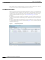
Understanding the Web Interface 5-5
Web Interface Design 5-6
Navigation Pane 5-7
Content Area 5-8
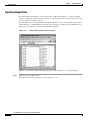
Importing and Exporting ACS Objects through the Web Interface 5-18
Supported ACS Objects 5-18
Creating Import Files 5-21
Downloading the Template from the Web Interface 5-21
Understanding the CSV Templates 5-22
Creating the Import File 5-22
Common Errors 5-25
Concurrency Conflict Errors 5-25
Deletion Errors 5-26
System Failure Errors 5-27
Accessibility 5-27
Display and Readability Features 5-27
Keyboard and Mouse Features 5-28
Obtaining Additional Accessibility Information
CHAPTER
6
Post-Installation Configuration Tasks
Configuring Minimal System Setup
5-28
6-1
6-1
Configuring ACS to Perform System Administration Tasks
Configuring ACS to Manage Access Policies
6-2
6-4
Configuring ACS to Monitor and Troubleshoot Problems in the Network
CHAPTER
7
Managing Network Resources
6-4
7-1
Network Device Groups 7-2
Creating, Duplicating, and Editing Network Device Groups 7-2
Deleting Network Device Groups 7-3
Creating, Duplicating, and Editing Network Device Groups Within a Hierarchy
Deleting Network Device Groups from a Hierarchy 7-5
Network Devices and AAA Clients
7-4
7-5
User Guide for Cisco Secure Access Control System 5.4
vi
OL-26225-01
Contents
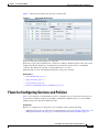
Viewing and Performing Bulk Operations for Network Devices
Exporting Network Devices and AAA Clients 7-7
Performing Bulk Operations for Network Resources and Users
Exporting Network Resources and Users 7-10
Creating, Duplicating, and Editing Network Devices 7-10
Configuring Network Device and AAA Clients 7-11
Displaying Network Device Properties 7-14
Deleting Network Devices 7-17
Configuring a Default Network Device
Working with OCSP Services 7-21
Creating, Duplicating, and Editing OCSP Servers
Deleting OCSP Servers 7-24
8
Managing Users and Identity Stores
7-8
7-17
Working with External Proxy Servers 7-19
Creating, Duplicating, and Editing External Proxy Servers
Deleting External Proxy Servers 7-21
CHAPTER
7-6
7-19
7-22
8-1
Overview 8-1
Internal Identity Stores 8-1
External Identity Stores 8-2
Identity Stores with Two-Factor Authentication
Identity Groups 8-3
Certificate-Based Authentication 8-3
Identity Sequences 8-4
8-3
Managing Internal Identity Stores 8-4
Authentication Information 8-5
Identity Groups 8-6
Creating Identity Groups 8-6
Deleting an Identity Group 8-7
Managing Identity Attributes 8-7
Standard Attributes 8-8
User Attributes 8-8
Host Attributes 8-9
Configuring Authentication Settings for Users 8-9
Creating Internal Users 8-11
Deleting Users from Internal Identity Stores 8-15
Viewing and Performing Bulk Operations for Internal Identity Store Users
Creating Hosts in Identity Stores 8-16
Deleting Internal Hosts 8-18
8-15
User Guide for Cisco Secure Access Control System 5.4
OL-26225-01
vii
Contents
Viewing and Performing Bulk Operations for Internal Identity Store Hosts 8-18
Management Hierarchy 8-19
Attributes of Management Hierarchy 8-19
Configuring AAA Devices for Management Hierarchy 8-19
Configuring Users or Hosts for Management Hierarchy 8-20
Configuring and Using UserIsInManagement Hierarchy Attribute 8-20
Configuring and Using HostIsInManagement Hierarchy Attributes 8-21
Managing External Identity Stores 8-22
LDAP Overview 8-22
Directory Service 8-23
Authentication Using LDAP 8-23
Multiple LDAP Instances 8-23
Failover 8-24
LDAP Connection Management 8-24
Authenticating a User Using a Bind Connection 8-24
Group Membership Information Retrieval 8-25
Attributes Retrieval 8-25
Certificate Retrieval 8-26
Creating External LDAP Identity Stores 8-26
Configuring an External LDAP Server Connection 8-27
Configuring External LDAP Directory Organization 8-29
Deleting External LDAP Identity Stores 8-33
Configuring LDAP Groups 8-33
Viewing LDAP Attributes 8-34
Leveraging Cisco NAC Profiler as an External MAB Database 8-34
Enabling the LDAP Interface on Cisco NAC Profiler to Communicate with ACS 8-35
Configuring NAC Profile LDAP Definition in ACS for Use in Identity Policy 8-37
Troubleshooting MAB Authentication with Profiler Integration 8-41
Microsoft AD 8-41
Machine Authentication 8-43
Attribute Retrieval for Authorization 8-44
Group Retrieval for Authorization 8-44
Certificate Retrieval for EAP-TLS Authentication 8-44
Concurrent Connection Management 8-44
User and Machine Account Restrictions 8-44
Machine Access Restrictions 8-45
Distributed MAR Cache 8-46
Dial-In Permissions 8-47
Callback Options for Dial-In users 8-48
Joining ACS to an AD Domain 8-49
User Guide for Cisco Secure Access Control System 5.4
viii
OL-26225-01
Contents
Configuring an AD Identity Store 8-49
Selecting an AD Group 8-53
Configuring AD Attributes 8-54
Configuring Machine Access Restrictions 8-56
RSA SecurID Server 8-57
Configuring RSA SecurID Agents 8-58
Creating and Editing RSA SecurID Token Servers 8-59
RADIUS Identity Stores 8-63
Supported Authentication Protocols 8-63
Failover 8-64
Password Prompt 8-64
User Group Mapping 8-64
Groups and Attributes Mapping 8-64
RADIUS Identity Store in Identity Sequence 8-65
Authentication Failure Messages 8-65
Username Special Format with Safeword Server 8-65
User Attribute Cache 8-66
Creating, Duplicating, and Editing RADIUS Identity Servers
8-66
Configuring CA Certificates 8-71
Adding a Certificate Authority 8-72
Editing a Certificate Authority and Configuring Certificate Revocation Lists
Deleting a Certificate Authority 8-74
Exporting a Certificate Authority 8-75
Configuring Certificate Authentication Profiles
8-75
Configuring Identity Store Sequences 8-77
Creating, Duplicating, and Editing Identity Store Sequences
Deleting Identity Store Sequences 8-80
CHAPTER
9
Managing Policy Elements
8-73
8-78
9-1
Managing Policy Conditions 9-1
Creating, Duplicating, and Editing a Date and Time Condition 9-3
Creating, Duplicating, and Editing a Custom Session Condition 9-5
Deleting a Session Condition 9-6
Managing Network Conditions 9-6
Importing Network Conditions 9-8
Exporting Network Conditions 9-9
Creating, Duplicating, and Editing End Station Filters 9-9
Creating, Duplicating, and Editing Device Filters 9-12
Creating, Duplicating, and Editing Device Port Filters 9-15
User Guide for Cisco Secure Access Control System 5.4
OL-26225-01
ix
Contents
Managing Authorizations and Permissions 9-17
Creating, Duplicating, and Editing Authorization Profiles for Network Access 9-18
Specifying Authorization Profiles 9-19
Specifying Common Attributes in Authorization Profiles 9-19
Specifying RADIUS Attributes in Authorization Profiles 9-22
Creating and Editing Security Groups 9-24
Creating, Duplicating, and Editing a Shell Profile for Device Administration 9-24
Defining General Shell Profile Properties 9-26
Defining Common Tasks 9-26
Defining Custom Attributes 9-29
Creating, Duplicating, and Editing Command Sets for Device Administration 9-29
Creating, Duplicating, and Editing Downloadable ACLs 9-32
Deleting an Authorizations and Permissions Policy Element 9-33
Configuring Security Group Access Control Lists 9-34
CHAPTER
10
Managing Access Policies
10-1
Policy Creation Flow 10-1
Network Definition and Policy Goals 10-2
Policy Elements in the Policy Creation Flow
Access Service Policy Creation 10-4
Service Selection Policy Creation 10-4
Customizing a Policy
10-3
10-4
Configuring the Service Selection Policy 10-5
Configuring a Simple Service Selection Policy 10-6
Service Selection Policy Page 10-6
Creating, Duplicating, and Editing Service Selection Rules
Displaying Hit Counts 10-10
Deleting Service Selection Rules 10-10
10-8
Configuring Access Services 10-11
Editing Default Access Services 10-11
Creating, Duplicating, and Editing Access Services 10-12
Configuring General Access Service Properties 10-13
Configuring Access Service Allowed Protocols 10-16
Configuring Access Services Templates 10-20
Deleting an Access Service 10-21
Configuring Access Service Policies 10-22
Viewing Identity Policies 10-22
Viewing Rules-Based Identity Policies
Configuring Identity Policy Rule Properties
10-24
10-25
User Guide for Cisco Secure Access Control System 5.4
x
OL-26225-01
Contents
Configuring a Group Mapping Policy 10-27
Configuring Group Mapping Policy Rule Properties 10-29
Configuring a Session Authorization Policy for Network Access 10-30
Configuring Network Access Authorization Rule Properties 10-32
Configuring Device Administration Authorization Policies 10-33
Configuring Device Administration Authorization Rule Properties 10-34
Configuring Device Administration Authorization Exception Policies 10-34
Configuring Shell/Command Authorization Policies for Device Administration
Configuring Authorization Exception Policies 10-36
Creating Policy Rules 10-38
Duplicating a Rule 10-39
Editing Policy Rules 10-39
Deleting Policy Rules 10-40
10-35
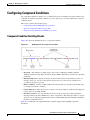
Configuring Compound Conditions 10-41
Compound Condition Building Blocks 10-41
Types of Compound Conditions 10-42
Using the Compound Expression Builder 10-45
Security Group Access Control Pages 10-46
Egress Policy Matrix Page 10-46
Editing a Cell in the Egress Policy Matrix 10-47
Defining a Default Policy for Egress Policy Page 10-47
NDAC Policy Page 10-48
NDAC Policy Properties Page 10-49
Network Device Access EAP-FAST Settings Page 10-51
Maximum User Sessions 10-51
Max Session User Settings 10-52
Max Session Group Settings 10-52
Max Session Global Setting 10-53
Purging User Sessions 10-54
Maximum User Session in Distributed Environment
Maximum User Session in Proxy Scenario 10-56
CHAPTER
11
Monitoring and Reporting in ACS
Authentication Records and Details
Dashboard Pages
10-55
11-1
11-2
11-2
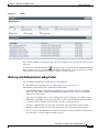
Working with Portlets 11-4
Working with Authentication Lookup Portlet 11-5
Running Authentication Lookup Report 11-6
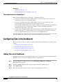
Configuring Tabs in the Dashboard
11-6
User Guide for Cisco Secure Access Control System 5.4
OL-26225-01
xi
Contents
Adding Tabs to the Dashboard 11-6
Adding Applications to Tabs 11-7
Renaming Tabs in the Dashboard 11-7
Changing the Dashboard Layout 11-8
Deleting Tabs from the Dashboard 11-8
CHAPTER
12
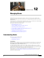
Managing Alarms
12-1
Understanding Alarms 12-1
Evaluating Alarm Thresholds 12-2
Notifying Users of Events 12-3
Viewing and Editing Alarms in Your Inbox
12-3
Understanding Alarm Schedules 12-9
Creating and Editing Alarm Schedules 12-9
Assigning Alarm Schedules to Thresholds 12-10
Deleting Alarm Schedules 12-11
Creating, Editing, and Duplicating Alarm Thresholds 12-11
Configuring General Threshold Information 12-13
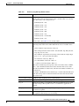
Configuring Threshold Criteria 12-14
Passed Authentications 12-14
Failed Authentications 12-16
Authentication Inactivity 12-18
TACACS Command Accounting 12-19
TACACS Command Authorization 12-20
ACS Configuration Changes 12-21
ACS System Diagnostics 12-22
ACS Process Status 12-23
ACS System Health 12-24
ACS AAA Health 12-25
RADIUS Sessions 12-26
Unknown NAD 12-27
External DB Unavailable 12-28
RBACL Drops 12-29
NAD-Reported AAA Downtime 12-31
Configuring Threshold Notifications 12-32
Deleting Alarm Thresholds
12-33
Configuring System Alarm Settings
12-34
Understanding Alarm Syslog Targets 12-35
Creating and Editing Alarm Syslog Targets
Deleting Alarm Syslog Targets 12-36
12-35
User Guide for Cisco Secure Access Control System 5.4
xii
OL-26225-01
Contents
CHAPTER
13
Managing Reports
13-1
Working with Favorite Reports 13-3
Adding Reports to Your Favorites Page 13-3
Viewing Favorite-Report Parameters 13-4
Editing Favorite Reports 13-5
Running Favorite Reports 13-5
Deleting Reports from Favorites 13-6
Sharing Reports
13-6
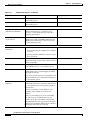
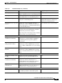
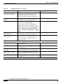
Working with Catalog Reports 13-7
Available Reports in the Catalog 13-7
Running Catalog Reports 13-11
Deleting Catalog Reports 13-12
Running Named Reports 13-13
Understanding the Report_Name Page 13-14
Enabling RADIUS CoA Options on a Device 13-17
Changing Authorization and Disconnecting Active RADIUS Sessions
Customizing Reports 13-19
Restoring Reports 13-20
13-18
Viewing Reports 13-20
About Standard Viewer 13-21
About Interactive Viewer 13-21
About the Interactive Viewer Context Menus 13-21
Navigating Reports 13-22
Using the Table of Contents 13-23
Exporting Report Data 13-24
Printing Reports 13-26
Saving Report Designs in Interactive Viewer 13-26
Formatting Reports in Interactive Viewer 13-27
Editing Labels 13-27
Formatting Labels 13-28
Formatting Data 13-28
Resizing Columns 13-29
Changing Column Data Alignment 13-29
Formatting Data in Columns 13-29
Formatting Data in Aggregate Rows 13-30
Formatting Data Types 13-30
Formatting Numeric Data 13-31
Formatting Fixed or Scientific Numbers or Percentages
Formatting Custom Numeric Data 13-33
13-32
User Guide for Cisco Secure Access Control System 5.4
OL-26225-01
xiii
Contents
Formatting String Data 13-33
Formatting Custom String Data 13-33
Formatting Date and Time 13-35
Formatting Custom Date and Time 13-35
Formatting Boolean Data 13-36
Applying Conditional Formats 13-37
Setting Conditional Formatting for Columns 13-38
Deleting Conditional Formatting 13-40
Setting and Removing Page Breaks in Detail Columns 13-40
Setting and Removing Page Breaks in a Group Column 13-41
Organizing Report Data 13-41
Displaying and Organizing Report Data 13-42
Reordering Columns in Interactive Viewer 13-42
Removing Columns 13-44
Hiding or Displaying Report Items 13-44
Hiding Columns 13-45
Displaying Hidden Columns 13-45
Merging Columns 13-45
Selecting a Column from a Merged Column 13-47
Sorting Data 13-47
Sorting a Single Column 13-47
Sorting Multiple Columns 13-47
Grouping Data 13-49
Adding Groups 13-50
Grouping Data Based on Date or Time 13-50
Removing an Inner Group 13-51
Creating Report Calculations 13-52
Understanding Supported Calculation Functions 13-53
Understanding Supported Operators 13-61
Using Numbers and Dates in an Expression 13-61
Using Multiply Values in Calculated Columns 13-62
Adding Days to an Existing Date Value 13-62
Subtracting Date Values in a Calculated Column 13-63
Working with Aggregate Data 13-63
Creating an Aggregate Data Row 13-65
Adding Additional Aggregate Rows 13-66
Deleting Aggregate Rows 13-67
Hiding and Filtering Report Data 13-67
Hiding or Displaying Column Data 13-67
Displaying Repeated Values 13-68
User Guide for Cisco Secure Access Control System 5.4
xiv
OL-26225-01
Contents
Hiding or Displaying Detail Rows in Groups or Sections 13-68
Working with Filters 13-69
Types of Filter Conditions 13-70
Setting Filter Values 13-71
Creating Filters 13-72
Modifying or Clearing a Filter 13-73
Creating a Filter with Multiple Conditions 13-73
Deleting One Filter Condition in a Filter that Contains Multiple Conditions
Filtering Highest or Lowest Values in Columns 13-75
13-75
Understanding Charts 13-76
Modifying Charts 13-77
Filtering Chart Data 13-77
Changing Chart Subtype 13-78
Changing Chart Formatting 13-78
CHAPTER
14
Troubleshooting ACS with the Monitoring and Report Viewer
Available Diagnostic and Troubleshooting Tools
Connectivity Tests 14-1
ACS Support Bundle 14-1
Expert Troubleshooter 14-2
Performing Connectivity Tests
14-1
14-1
14-3
Downloading ACS Support Bundles for Diagnostic Information
14-4
Working with Expert Troubleshooter 14-6
Troubleshooting RADIUS Authentications 14-6
Executing the Show Command on a Network Device 14-10
Evaluating the Configuration of a Network Device 14-10
Comparing SGACL Policy Between a Network Device and ACS 14-12
Comparing the SXP-IP Mappings Between a Device and its Peers 14-12
Comparing IP-SGT Pairs on a Device with ACS-Assigned SGT Records 14-15
Comparing Device SGT with ACS-Assigned Device SGT 14-16
CHAPTER
15
Managing System Operations and Configuration in the Monitoring and Report Viewer
Configuring Data Purging and Incremental Backup
Configuring NFS Staging 15-7
Restoring Data from a Backup
15-3
15-7
Viewing Log Collections 15-8
Log Collection Details Page
Recovering Log Messages
15-1
15-10
15-12
User Guide for Cisco Secure Access Control System 5.4
OL-26225-01
xv
Contents
Viewing Scheduled Jobs
Viewing Process Status
15-12
15-14
Viewing Data Upgrade Status
15-15
Viewing Failure Reasons
15-15
Editing Failure Reasons
15-15
Specifying E-Mail Settings
15-16
Configuring SNMP Preferences
15-16
Understanding Collection Filters 15-17
Creating and Editing Collection Filters
Deleting Collection Filters 15-18
Configuring System Alarm Settings
15-17
15-18
Configuring Alarm Syslog Targets
15-18
Configuring Remote Database Settings 15-18
Changing the Port Numbers for Oracle Database
CHAPTER
16
Managing System Administrators
15-20
16-1
Understanding Administrator Roles and Accounts
Understanding Authentication 16-3
16-2
Configuring System Administrators and Accounts
16-3
Understanding Roles 16-3
Assigning Roles 16-3
Assigning Static Roles 16-4
Assigning Dynamic Roles 16-4
Permissions 16-4
Predefined Roles 16-5
Changing Role Associations 16-6
Administrator Accounts and Role Association
Recovery Administrator Account 16-7
16-6
Creating, Duplicating, Editing, and Deleting Administrator Accounts
16-7
Viewing Predefined Roles 16-9
Viewing Role Properties 16-10
Configuring Authentication Settings for Administrators
Configuring Session Idle Timeout
16-10
16-12
Configuring Administrator Access Settings
16-13
Working with Administrative Access Control 16-14
Administrator Identity Policy 16-15
Viewing Rule-Based Identity Policies 16-16
User Guide for Cisco Secure Access Control System 5.4
xvi
OL-26225-01
Contents
Configuring Identity Policy Rule Properties 16-18
Administrator Authorization Policy 16-19
Configuring Administrator Authorization Policies 16-19
Configuring Administrator Authorization Rule Properties
Administrator Login Process 16-21
Resetting the Administrator Password
16-22
Changing the Administrator Password 16-22
Changing Your Own Administrator Password
Resetting Another Administrator’s Password
CHAPTER
17
Configuring System Operations
16-20
16-22
16-23
17-1
Understanding Distributed Deployment 17-2
Activating Secondary Servers 17-3
Removing Secondary Servers 17-4
Promoting a Secondary Server 17-4
Understanding Local Mode 17-4
Understanding Full Replication 17-5
Specifying a Hardware Replacement 17-5
Scheduled Backups 17-6
Creating, Duplicating, and Editing Scheduled Backups
Backing Up Primary and Secondary Instances
17-6
17-8
Synchronizing Primary and Secondary Instances After Backup and Restore
17-9
Editing Instances 17-9
Viewing and Editing a Primary Instance 17-9
Viewing and Editing a Secondary Instance 17-13
Deleting a Secondary Instance 17-13
Activating a Secondary Instance
17-14
Registering a Secondary Instance to a Primary Instance
17-14
Deregistering Secondary Instances from the Distributed System Management Page
Deregistering a Secondary Instance from the Deployment Operations Page
17-17
Promoting a Secondary Instance from the Distributed System Management Page
Promoting a Secondary Instance from the Deployment Operations Page
17-17
17-18
17-19
Replicating a Secondary Instance from a Primary Instance 17-19
Replicating a Secondary Instance from the Distributed System Management Page
Replicating a Secondary Instance from the Deployment Operations Page 17-20
Changing the IP address of a Primary Instance from the Primary Server 17-21
Failover 17-22
Using the Deployment Operations Page to Create a Local Mode Instance
17-20
17-23
User Guide for Cisco Secure Access Control System 5.4
OL-26225-01
xvii
Contents
Creating, Duplicating, Editing, and Deleting Software Repositories 17-24
Managing Software Repositories from the Web Interface and CLI 17-25
CHAPTER
18
Managing System Administration Configurations
18-1
Configuring Global System Options 18-1
Configuring TACACS+ Settings 18-1
Configuring EAP-TLS Settings 18-2
Configuring PEAP Settings 18-3
Configuring EAP-FAST Settings 18-3
Generating EAP-FAST PAC 18-4
Configuring RSA SecurID Prompts
18-4
Managing Dictionaries 18-5
Viewing RADIUS and TACACS+ Attributes 18-5
Creating, Duplicating, and Editing RADIUS Vendor-Specific Attributes 18-6
Creating, Duplicating, and Editing RADIUS Vendor-Specific Subattributes 18-7
Viewing RADIUS Vendor-Specific Subattributes 18-9
Configuring Identity Dictionaries 18-10
Creating, Duplicating, and Editing an Internal User Identity Attribute 18-10
Configuring Internal Identity Attributes 18-11
Deleting an Internal User Identity Attribute 18-12
Creating, Duplicating, and Editing an Internal Host Identity Attribute 18-13
Deleting an Internal Host Identity Attribute 18-13
Adding Static IP address to Users in Internal Identity Store 18-14
Configuring Local Server Certificates
18-14
Adding Local Server Certificates 18-14
Importing Server Certificates and Associating Certificates to Protocols
Generating Self-Signed Certificates 18-16
Generating a Certificate Signing Request 18-17
Binding CA Signed Certificates 18-18
Editing and Renewing Certificates 18-18
Deleting Certificates 18-19
Exporting Certificates 18-20
Viewing Outstanding Signing Requests 18-20
18-15
Configuring Logs 18-21
Configuring Remote Log Targets 18-21
Deleting a Remote Log Target 18-23
Configuring the Local Log 18-24
Deleting Local Log Data 18-24
Configuring Logging Categories 18-24
User Guide for Cisco Secure Access Control System 5.4
xviii
OL-26225-01
Contents
Configuring Global Logging Categories 18-25
Configuring Per-Instance Logging Categories 18-29
Configuring Per-Instance Security and Log Settings 18-30
Configuring Per-Instance Remote Syslog Targets 18-31
Displaying Logging Categories 18-32
Configuring the Log Collector 18-33
Viewing the Log Message Catalog 18-33
Licensing Overview 18-34
Types of Licenses 18-34
Installing a License File 18-35
Viewing the Base License 18-36
Upgrading the Base Server License
Viewing License Feature Options
18-38
Adding Deployment License Files
18-39
Deleting Deployment License Files
18-37
18-40
Available Downloads 18-40
Downloading Migration Utility Files 18-41
Downloading UCP Web Service Files 18-41
Downloading Sample Python Scripts 18-41
Downloading Rest Services 18-42
CHAPTER
19
Understanding Logging
19-1
About Logging 19-1
Using Log Targets 19-2
Logging Categories 19-2
Global and Per-Instance Logging Categories 19-4
Log Message Severity Levels 19-4
Local Store Target 19-5
Critical Log Target 19-7
Remote Syslog Server Target 19-8
Monitoring and Reports Server Target 19-10
Viewing Log Messages 19-10
Debug Logs 19-11
ACS 4.x Versus ACS 5.4 Logging
APPENDIX
A
AAA Protocols
19-12
A-1
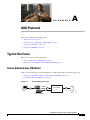
Typical Use Cases A-1
Device Administration (TACACS+)
A-1
User Guide for Cisco Secure Access Control System 5.4
OL-26225-01
xix
Contents
Session Access Requests (Device Administration [TACACS+])
Command Authorization Requests A-2
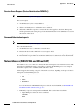
Network Access (RADIUS With and Without EAP) A-2
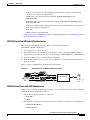
RADIUS-Based Flow Without EAP Authentication A-3
RADIUS-Based Flows with EAP Authentication A-3
Access Protocols—TACACS+ and RADIUS
Overview of TACACS+
A-2
A-5
A-5
Overview of RADIUS A-6
RADIUS VSAs A-6
ACS 5.4 as the AAA Server A-7
RADIUS Attribute Support in ACS 5.4 A-8
RADIUS Attribute Rewrite Operation A-9
RADIUS Access Requests A-11
APPENDIX
B
Authentication in ACS 5.4
B-1
Authentication Considerations
B-1
Authentication and User Databases
PAP
B-2
RADIUS PAP Authentication
EAP
B-1
B-3
B-3
EAP-MD5 B-5
Overview of EAP-MD5 B-5
EAP- MD5 Flow in ACS 5.4 B-5
EAP-TLS B-5
Overview of EAP-TLS B-6
User Certificate Authentication B-6
PKI Authentication B-7
PKI Credentials B-8
PKI Usage B-8
Fixed Management Certificates B-9
Importing Trust Certificates B-9
Acquiring Local Certificates B-9
Importing the ACS Server Certificate B-10
Initial Self-Signed Certificate Generation B-10
Certificate Generation B-10
Exporting Credentials B-11
Credentials Distribution B-12
Hardware Replacement and Certificates B-12
Securing the Cryptographic Sensitive Material B-12
User Guide for Cisco Secure Access Control System 5.4
xx
OL-26225-01
Contents
Private Keys and Passwords Backup
EAP-TLS Flow in ACS 5.4 B-13
B-13
PEAPv0/1 B-14
Overview of PEAP B-15
Supported PEAP Features B-15
PEAP Flow in ACS 5.4 B-17
Creating the TLS Tunnel B-18
Authenticating with MSCHAPv2 B-19
EAP-FAST B-19
Overview of EAP-FAST B-19
EAP-FAST Benefits B-21
EAP-FAST in ACS 5.4 B-21
About Master-Keys B-22
About PACs B-22
Provisioning Modes B-23
Types of PACs B-23
ACS-Supported Features for PACs B-25
Master Key Generation and PAC TTLs B-27
EAP-FAST for Allow TLS Renegotiation B-27
EAP-FAST Flow in ACS 5.4. B-27
EAP-FAST PAC Management B-28
Key Distribution Algorithm B-29
EAP-FAST PAC-Opaque Packing and Unpacking
Revocation Method B-29
PAC Migration from ACS 4.x B-29
EAP Authentication with RADIUS Key Wrap
B-30
EAP-MSCHAPv2 B-30
Overview of EAP-MSCHAPv2 B-31
MSCHAPv2 for User Authentication B-31
MSCHAPv2 for Change Password B-31
Windows Machine Authentication Against AD
EAP- MSCHAPv2 Flow in ACS 5.4 B-32
CHAP
B-32
LEAP
B-32
Certificate Attributes B-32
Certificate Binary Comparison B-33
Rules Relating to Textual Attributes
Certificate Revocation B-34
Machine Authentication
B-29
B-31
B-33
B-35
User Guide for Cisco Secure Access Control System 5.4
OL-26225-01
xxi
Contents
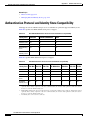
Authentication Protocol and Identity Store Compatibility
APPENDIX
C
Open Source License Acknowledgements
Notices C-1
OpenSSL/Open SSL Project
License Issues C-1
B-36
C-1
C-1
C-3
GLOSSARY
INDEX
User Guide for Cisco Secure Access Control System 5.4
xxii
OL-26225-01
Preface
Revised: November 13, 2013
This guide describes how to use Cisco Secure Access Control System (ACS) 5.4.
Audience
This guide is for security administrators who use ACS, and who set up and maintain network and
application security.
Document Conventions
This guide uses the convention whereby the symbol ^ represents the key labeled Control. For example,
the key combination ^z means hold down the Control key while you press the z key.
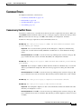
Command descriptions use these conventions:
•
Examples that contain system prompts denote interactive sessions, indicating the commands that
you should enter at the prompt. The system prompt indicates the current level of the EXEC
command interpreter. For example, the prompt Router> indicates that you should be at the user
level, and the prompt Router# indicates that you should be at the privileged level. Access to the
privileged level usually requires a password.
•
Commands and keywords are in boldface font.
•
Arguments for which you supply values are in italic font.
•
Elements in square brackets ([ ]) are optional.
•
Alternative keywords of which you must choose one are grouped in braces ({}) and separated by
vertical bars (|).
Examples use these conventions:
•
Terminal sessions and sample console screen displays are in
•
Information you enter is in boldface
•
Nonprinting characters, such as passwords, are in angle brackets (< >).
•
Default responses to system prompts are in square brackets ([]).
•
An exclamation point (!) at the beginning of a line indicates a comment line.
screen
screen
font.
font.
User Guide for Cisco Secure Access Control System 5.4
OL-26225-01
xxiii
Preface
Caution
Timesaver
Note
Means reader be careful. You are capable of doing something that might result in equipment damage or
loss of data.
Means the described action saves time. You can save time by performing the action described in the
paragraph.
Means reader take note. Notes identify important information that you should reflect upon before
continuing, contain helpful suggestions, or provide references to materials not contained in the
document.
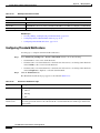
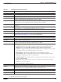
Documentation Updates
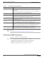
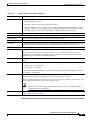
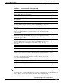
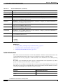
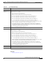
Table 1 lists the updates to the User Guide for Cisco Secure Access Control System 5.4.
Table 1
Updates to the User Guide for Cisco Secure Access Control System 5.4
Date
Description
9/26/2013
Fixed the following bugs:
•
CSCuh90646
•
CSCuj24445
10/30/2012
Updated the guide with Cisco 3415 Secure Access Control System information.
10/23/2012
Cisco Secure Access Control System, Release 5.4.
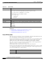
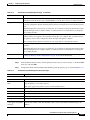
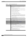
Related Documentation
Table 2 lists a set of related technical documentation available on Cisco.com. To find end-user
documentation for all products on Cisco.com, go to: http://www.cisco.com/go/techdocs.
Select Products > Security > Access Control and Policy > Policy and Access Management > Cisco
Secure Access Control System.
Note
It is possible for the printed and electronic documentation to be updated after original publication.
Therefore, you should also review the documentation on http://www.cisco.com for any updates.
User Guide for Cisco Secure Access Control System 5.4
xxiv
OL-26225-01
Preface
Table 2
Product Documentation
Document Title
Available Formats
Cisco Secure Access Control System In-Box
Documentation and China ROHS Pointer Card
http://www.cisco.com/en/US/products/ps9911/
products_licensing_information_listing.html
License and Documentation Guide for Cisco
Secure Access Control System 5.4
http://www.cisco.com/en/US/products/ps9911/
products_documentation_roadmaps_list.html
Release Notes for Cisco Secure Access Control
System 5.4
http://www.cisco.com/en/US/products/ps9911/
prod_release_notes_list.html
Migration Guide for Cisco Secure Access
Control System 5.4
http://www.cisco.com/en/US/products/ps9911/
prod_installation_guides_list.html
CLI Reference Guide for Cisco Secure Access
Control System 5.4
http://www.cisco.com/en/US/products/ps9911/
prod_command_reference_list.html
Supported and Interoperable Devices and
Software for Cisco Secure Access Control
System 5.4
http://www.cisco.com/en/US/products/ps9911/
products_device_support_tables_list.html
Installation and Upgrade Guide for Cisco
Secure Access Control System 5.4
http://www.cisco.com/en/US/products/ps9911/
prod_installation_guides_list.html
Software Developer’s Guide for Cisco Secure
Access Control System 5.4
http://www.cisco.com/en/US/products/ps9911/
products_programming_reference_guides_list.html
Regulatory Compliance and Safety Information http://www.cisco.com/en/US/docs/net_mgmt/cisco_
for Cisco Secure Access Control System 5.4
secure_access_control_system/5.4/regulatory/comp
liance/csacsrcsi.html
Obtaining Documentation and Submitting a Service Request
For information on obtaining documentation, submitting a service request, and gathering additional
information, see the monthly What’s New in Cisco Product Documentation, which also lists all new and
revised Cisco technical documentation, at:
http://www.cisco.com/en/US/docs/general/whatsnew/whatsnew.html
Subscribe to the What’s New in Cisco Product Documentation as a Really Simple Syndication (RSS) feed
and set content to be delivered directly to your desktop using a reader application. The RSS feeds are a free
service and Cisco currently supports RSS version 2.0.
User Guide for Cisco Secure Access Control System 5.4
OL-26225-01
xxv
Preface
User Guide for Cisco Secure Access Control System 5.4
xxvi
OL-26225-01
CH A P T E R
1
Introducing ACS 5.4
This section contains the following topics:
•
Overview of ACS, page 1-1
•
ACS Distributed Deployment, page 1-2
•
ACS Management Interfaces, page 1-3
Overview of ACS
ACS is a policy-based security server that provides standards-compliant Authentication, Authorization,
and Accounting (AAA) services to your network. ACS facilitates the administrative management of
Cisco and non-Cisco devices and applications.
As a dominant enterprise network access control platform, ACS serves as an integration point for
network access control and identity management.
ACS 5.x provides a rule-based policy model that allows you to control network access based on dynamic
conditions and attributes. The rule-based policy is designed to meet complex access policy needs. For
more information on the rule-based policy model in ACS, see Chapter 3, “ACS 5.x Policy Model.”
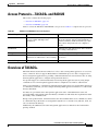
Within the greater context of two major AAA protocols—RADIUS and TACACS+—ACS provides the
following basic areas of functionality:
•
Under the framework of the RADIUS protocol, ACS controls the wired and wireless access by users
and host machines to the network and manages the accounting of the network resources used.
ACS supports multiple RADIUS-based authentication methods that includes PAP, CHAP,
MSCHAPv1, MSCHAPv2. It also supports many members of the EAP family of protocols, such as
EAP-MD5, LEAP, PEAP, EAP-FAST, and EAP-TLS.
In association with PEAP or EAP-FAST, ACS also supports EAP-MSCHAPv2, EAP-GTC, and
EAP-TLS. For more information on authentication methods, see Authentication in ACS 5.4.
•
Under the framework of the TACACS+ protocol, ACS helps to manage Cisco and non-Cisco
network devices such as switches, wireless access points, routers, and gateways. It also helps to
manage services and entities such as dialup, Virtual Private Network (VPN), and firewall.
ACS is the point in your network that identifies users and devices that try to connect to your network.
This identity establishment can occur directly by using the ACS internal identity repository for local user
authentication or by using external identity repositories.
For example, ACS can use Active Directory as an external identity repository, to authenticate a user to
grant the user access to the network. For more information about creating identities and supported
identity services, see Chapter 8, “Managing Users and Identity Stores.”
User Guide for Cisco Secure Access Control System 5.4
OL-26225-01
1-1
Chapter 1
Introducing ACS 5.4
ACS Distributed Deployment
ACS provides advanced monitoring, reporting, and troubleshooting tools that help you administer and
manage your ACS deployments. For more information on the monitoring, reporting, and troubleshooting
capabilities of ACS, see Chapter 11, “Monitoring and Reporting in ACS.”.
For more information about using ACS for device administration and network access scenarios, see
Chapter 4, “Common Scenarios Using ACS.”
Cisco Secure ACS:
•
Enforces access policies for VPN and wireless users.
•
Provides simplified device administration.
•
Provides advanced monitoring, reporting, and troubleshooting tools.
There are several changes and enhancements in ACS 5.4 compared to ACS 5.3. For a complete list of
new and changed features, see:
http://www.cisco.com/en/US/docs/net_mgmt/cisco_secure_access_control_system/5.4/release/notes/
acs_54_rn.html.
Related Topics
•
ACS Distributed Deployment, page 1-2
•
ACS Management Interfaces, page 1-3
ACS Distributed Deployment
ACS 5.4 is delivered preinstalled on a standard Cisco Linux-based appliance, and supports a fully
distributed deployment.
An ACS deployment can consist of a single instance, or multiple instances deployed in a distributed
manner, where all instances in a system are managed centrally. One ACS instance becomes the primary
instance and you can register additional ACS instances to the primary instance as secondary instances.
All instances have the configuration for the entire deployment, which provides redundancy for
configuration data.
The primary instance centralizes the configuration of the instances in the deployment. Configuration
changes made in the primary instance are automatically replicated to the secondary instance.
You can force a full replication to the secondary instance. Full replication is used when a new secondary
instance is registered and in other cases when the replication gap between the secondary instance and
the primary instance is significant.
Related Topic
•
ACS 4.x and 5.4 Replication, page 1-2
ACS 4.x and 5.4 Replication
In ACS 4.x, you must select the database object types (or classes) you wish to replicate from primary
instance to the secondary instance. When you replicate an object, a complete configuration copy is made
on the secondary instance.
In ACS 5.4, any configuration changes made in the primary instance are immediately replicated to the
secondary instance. Only the configuration changes made since the last replication are propagated to the
secondary instance.
User Guide for Cisco Secure Access Control System 5.4
1-2
OL-26225-01
Chapter 1
Introducing ACS 5.4
ACS Licensing Model
ACS 4.x did not provide incremental replication, only full replication, and there was service downtime
for replication. ACS 5.4 provides incremental replications with no service downtime.
You can also force a full replication to the secondary instance if configuration changes do not replicate
it. Full replication is used when a new secondary instance is registered and other cases when the
replication gap between the secondary instance and the primary instance is significant.
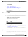
Table 1-1 lists some of the differences between ACS 4.x and 5.4 replication.
Table 1-1
Differences Between ACS 4.x and 5.4 Replication
ACS 4.x
ACS 5.4
You can choose the data items to be replicated.
You cannot choose the data items to be replicated.
All data items, by default are replicated.
Supports multi-level or cascading replication.
Supports only a fixed flat replication. Cascading
replication is not supported.
Some data items, such as the external database
configurations, are not replicated.
All data items are replicated except the database
key, database certificate, and master keys. The
server certificates, Certificate Signing Requests
(CSRs), and private keys are replicated, but they
are not shown in the interface.
For more information about setting up a distributed deployment, see Configuring System Operations,
page 17-1.
Note
Replication does not work in ACS servers if you use the Cisco Overlay Transport Virtualization
technology in your Virtual Local Area Network.
Note
Network Address Translation (NAT) is not supported in an ACS distributed deployment environment.
That is, if the network address of a primary or secondary instance is translated, then the database
replication may not work properly, and it may display a shared secret mismatch error.
ACS Licensing Model
You must have a valid license to operate ACS; ACS prompts you to install a valid base license when you
first access the web interface. Each server requires a unique base license in a distributed deployment.
For information about the types of licenses you can install, see Types of Licenses, page 18-34. For more
information about licenses, see Licensing Overview, page 18-34.
Related Topic
•
ACS Distributed Deployment, page 1-2
ACS Management Interfaces
This section contains the following topics:
User Guide for Cisco Secure Access Control System 5.4
OL-26225-01
1-3
Chapter 1
Introducing ACS 5.4
ACS Management Interfaces
•
ACS Web-based Interface, page 1-4
•
ACS Command Line Interface, page 1-4
•
ACS Programmatic Interfaces, page 1-5
ACS Web-based Interface
You can use the ACS web-based interface to fully configure your ACS deployment, and perform
monitoring and reporting operations. The web interface provides a consistent user experience, regardless
of the particular area that you are configuring.
The ACS web interface is supported on HTTPS-enabled Microsoft Internet Explorer versions from 6.x
to 9.x and Mozilla Firefox versions from 3.x to 10.x.
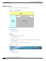
The new web interface design and organization:
•
Reflects the new policy model, which is organized around the user’s view of policy administration.
The new policy model is easier to use, as it separates the complex interrelationships that previously
existed among policy elements.
For example, user groups, network device groups (NDGs), network access filters, network access
profiles, and so on.
•
Presents the configuration tasks in a logical order that you can follow for many common scenarios.
For example, first you configure conditions and authorizations for policies in the Policy Elements
drawer, and then you move on to the Policies drawer to configure the policies with the defined policy
elements.
•
Provides new page functionality, such as sorting and filtering lists of items.
See “Using the Web Interface” section on page 5-3 for more information.
Related Topics
•
ACS Command Line Interface, page 1-4
ACS Command Line Interface
You can use the ACS command-line interface (CLI), a text-based interface, to perform some
configuration and operational tasks and monitoring. Access to the ACS-specific CLI requires
administrator authentication by ACS 5.4.
You do not need to be an ACS administrator or log into ACS 5.4 to use the non-ACS configuration mode.
ACS configuration mode command sessions are logged to the diagnostics logs.
ACS 5.4 is shipped on the Cisco 1121 Secure Access Control System (CSACS-1121) or on the Cisco
3415 Secure Access Control System (CSACS-3415). The ADE-OS software supports these command
modes:
•
EXEC—Use these commands to perform system-level operation tasks. For example, install, start,
and stop application; copy files and installations; restore backups; and display information.
In addition, certain EXEC mode commands have ACS-specific abilities. For example, start an ACS
instance, display and export ACS logs, and reset an ACS configuration to factory default settings.
Such commands are specifically mentioned in the documentation
•
ACS configuration—Use these commands to set the debug log level (enable or disable) for the ACS
management and runtime components, and show system settings.
User Guide for Cisco Secure Access Control System 5.4
1-4
OL-26225-01
Chapter 1
Introducing ACS 5.4
Hardware Models Supported by ACS
•
Note
Configuration—Use these commands to perform additional configuration tasks for the appliance
server in an ADE-OS environment.
The CLI includes an option to reset the configuration that, when issued, resets all ACS configuration
information, but retains the appliance settings such as network configuration.
For information about using the CLI, see the Command Line Interface Reference Guide for Cisco Secure
Access Control System 5.4.
Related Topic
•
ACS Web-based Interface, page 1-4
ACS Programmatic Interfaces
ACS 5.4 provides web services and command-line interface (CLI) commands that allow software
developers and system integrators to programmatically access some ACS features and functions. ACS
5.4 also provides you access to the Monitoring and Report Viewer database that you can use to create
custom applications to monitor and troubleshoot ACS.
The UCP web service allows users, defined in the ACS internal database, to first authenticate and then
change their own password. ACS exposes the UCP web service to allow you to create custom web-based
applications that you can deploy in your enterprise.
The Monitoring and Report Viewer web services allow you to create custom applications to track and
troubleshoot events in ACS.
You can develop shell scripts using the CLI commands that ACS offers to perform create, read, update,
and delete (CRUD) operations on ACS objects. You can also create an automated shell script to perform
bulk operations.
The REST PI (Representational State Transfer Programming Interface) allows you to manage entities
such as users, hosts, identity groups, network devices, network device groups, and network device group
types on your own management applications and move these entities into ACS. This way you can define
these entities and then use them on your own systems and on ACS.
For more information on how to access these web services and their functionalities, see
http://www.cisco.com/en/US/docs/net_mgmt/cisco_secure_access_control_system/5.4/sdk/
acs_sdk.html.
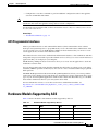
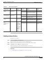
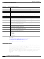
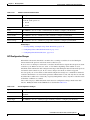
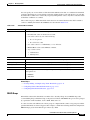
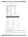
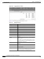
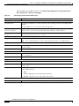
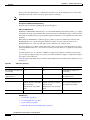
Hardware Models Supported by ACS
Table 1-2 shows the details of the hardware models supported by ACS 5.4.
Table 1-2
Hardware Models Supported by ACS 5.4
Config
HDD
RAM
NIC
UCS 3415
500 GB
8 GB
2 x 2 (4-1 Gb)
IBM 1121
2 x 250GB
4GB
4X10,100,1000 RJ-45
CAM25-1-2-4.
2 x 250GB
4 x 1GB
2 x 1GE
VMware ESX i5.0
60 to 750 GB
4GB
2 NICs
User Guide for Cisco Secure Access Control System 5.4
OL-26225-01
1-5
Chapter 1
Introducing ACS 5.4
Hardware Models Supported by ACS
User Guide for Cisco Secure Access Control System 5.4
1-6
OL-26225-01
CH A P T E R
2
Migrating from ACS 4.x to ACS 5.4
ACS 4.x stores policy and authentication information, such as TACACS+ command sets, in the user and
user group records. In ACS 5.4, policy and authentication information are independent shared
components that you use as building blocks when you configure policies.
The most efficient way to make optimal use of the new policy model is to rebuild policies by using the
building blocks, or policy elements, of the new policy model. This method entails creating appropriate
identity groups, network device groups (NDGs), conditions, authorization profiles, and rules.
ACS 5.4 provides a migration utility to transfer data from migration-supported versions of ACS 4.x to
an ACS 5.4 machine. The ACS 5.4 migration process requires, in some cases, administrative intervention
to manually resolve data before you import it to ACS 5.4.
This process is different from the process of upgrading from versions of ACS 3.x to ACS 4.x, where the
ACS 4.x system works the same way as ACS 3.x and no administrative intervention is required.
The migration utility in ACS 5.4 supports multiple-instance migration that migrates all ACS 4.x servers
in your deployment to ACS 5.4. For more information on multiple-instance migration, see
http://www.cisco.com/en/US/docs/net_mgmt/cisco_secure_access_control_system/5.4/migration/
guide/migration_guide.html.
Upgrade refers to the process of transferring data from ACS 5.3 servers to ACS 5.4. For information on
the upgrade process, refer to
http://www.cisco.com/en/US/docs/net_mgmt/cisco_secure_access_control_system/5.4/installation/
guide/csacs_upg.html.
This chapter contains the following sections:
•
Overview of the Migration Process, page 2-2
•
Before You Begin, page 2-3
•
Downloading Migration Files, page 2-3
•
Migrating from ACS 4.x to ACS 5.4, page 2-3
•
Functionality Mapping from ACS 4.x to ACS 5.4, page 2-5
•
Common Scenarios in Migration, page 2-7
User Guide for Cisco Secure Access Control System 5.4
OL-26225-01
2-1
Chapter 2
Migrating from ACS 4.x to ACS 5.4
Overview of the Migration Process
Overview of the Migration Process
The Migration utility completes the data migration process in two phases:
•
Analysis and Export
•
Import
In the Analysis and Export phase, you identify the objects that you want to export into 5.4. The Migration
utility analyses the objects, consolidates the data, and exports it.
After the Analysis and Export phase is complete, the Migration utility generates a report that lists any
data compatibility errors, which you can manually resolve to successfully import these objects into 5.4.
The Analysis and Export phase is an iterative process that you can rerun many times to ensure that there
are no errors in the data to be imported. After you complete the Analysis and Export phase, you can run
the import phase to import data into ACS 5.4.
This section contains the following topics:
•
Migration Requirements, page 2-2
•
Supported Migration Versions, page 2-2
Migration Requirements
To run the Migration utility, you must deploy the following machines:
•
The source ACS 4.x machine—This machine can either be an ACS 4.x solution engine or a ACS for
Windows 4.x machine. The source machine must be running a migration-supported version of ACS.
See Supported Migration Versions, page 2-2 for more information.
•
The migration machine—This machine must be a Windows platform that runs the same version of
ACS (including the patch) as the source machine. The migration machine cannot be an ACS
production machine or an ACS appliance machine. It has to be a Windows server running ACS for
Windows. The migration machine requires 2 GB RAM.
•
The target ACS 5.4 machine—Back up your ACS 5.4 configuration data and ensure that the
migration interface is enabled on ACS 5.4 before you begin the import process. We recommend that
you import data into a fresh ACS 5.4 database. To enable the migration interface, from the ACS CLI,
enter:
acs config-web-interface migration enable
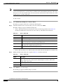
Supported Migration Versions
ACS 5.4 supports migration from the following ACS 4.x versions:
•
ACS 4.1.1.24
•
ACS 4.1.4
•
ACS 4.2.0.124
•
ACS 4.2.1
User Guide for Cisco Secure Access Control System 5.4
2-2
OL-26225-01
Chapter 2
Migrating from ACS 4.x to ACS 5.4
Before You Begin
Note
You must install the latest patch for the supported migration versions listed here. Also, if you have any
other version of ACS 4.x installed, you must upgrade to one of the supported versions and install the
latest patch for that version before you can migrate to ACS 5.4.
Before You Begin
Before you migrate data from ACS 4.x to ACS 5.4, ensure that you:
•
Check for database corruption issues in the ACS 4.x source machine.
•
Have the same ACS versions on the source and migration machines (including the patch).
•
Have configured a single IP address on the migration machine.
•
Take a backup of the source ACS 4.x data.
•
Have full network connectivity between the migration machine and the ACS 5.4 server.
•
Have enabled the migration interface on the ACS 5.4 server.
•
Use only the default superadmin account for ACS 5.4, acsadmin while running the Migration utility.
You cannot use the remote desktop to connect to the migration machine to run the Migration Utility. You
must run the Migration Utility on the migration machine; or, use VNC to connect to the migration
machine.
Note
ACS 5.4 migration utility is not supported on Windows 2008 64 bit.
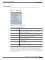
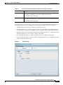
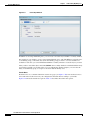
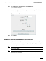
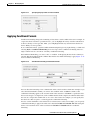
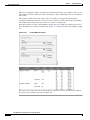
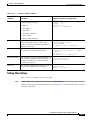
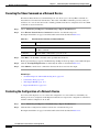
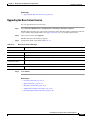
Downloading Migration Files
To download migration application files and the migration guide for ACS 5.4:
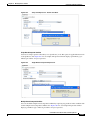
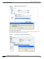
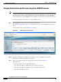
Step 1
Select System Administration > Downloads > Migration Utility.
The Migration from 4.x page appears.
Step 2
Click Migration application files, to download the application file you want to use to run the migration
utility.
Step 3
Click Migration Guide, to download Migration Guide for Cisco Secure Access Control System 5.4.
Migrating from ACS 4.x to ACS 5.4
You can migrate data from any of the migration-supported versions of ACS 4.x to ACS 5.4. The
migration utility migrates the following ACS 4.x data entities:
•
Network Device Groups (NDGs)
•
AAA Clients and Network Devices
•
Internal Users
User Guide for Cisco Secure Access Control System 5.4
OL-26225-01
2-3
Chapter 2
Migrating from ACS 4.x to ACS 5.4
Migrating from ACS 4.x to ACS 5.4
Note
•
User-Defined Fields (from the Interface Configuration section)
•
User Groups
•
Shared Shell Command Authorization Sets
•
User TACACS+ Shell Exec Attributes (migrated to user attributes)
•
Group TACACS+ Shell Exec Attributes (migrated to shell profiles)
•
User TACACS+ Command Authorization Sets
•
Group TACACS+ Command Authorization Sets
•
Shared, Downloadable ACLs
•
EAP-FAST Master Keys
•
Shared RADIUS Authorization Components (RACs)
•
RADIUS VSAs
The Migration utility does not migrate public key infrastructure (PKI) configuration data and does not
support certificate migration.
To migrate data from ACS 4.x to ACS 5.4:
Step 1
Upgrade the ACS 4.x version to a migration-supported version if your ACS 4.x server currently does not
run one of the migration-supported versions.
For a list of migration-supported ACS versions, see Supported Migration Versions, page 2-2.
Step 2
Install the same migration-supported version of ACS on the migration machine, which is a Windows
server.
Step 3
Back up the ACS 4.x data and restore it on the migration machine.
Step 4
Place the Migration utility on the migration machine.
You can get the Migration utility from the Installation and Recovery DVD.
Step 5
Run the Analyze and Export phase of the Migration utility on the migration machine.
Step 6
Resolve any issues in the Analyze and Export phase.
Step 7
Run the Import phase of the Migration utility on the migration machine.
The import phase imports data into the 5.4 server.
Note
If you have a large internal database, then we recommend that you import the data into a standalone 5.x
primary server and not to a server that is connected to several secondary servers. After data migration is
complete, you can register the secondary servers to the standalone 5.x primary server.
For detailed information about using the migration utility, refer to
http://www.cisco.com/en/US/docs/net_mgmt/cisco_secure_access_control_system/5.4/migration/
guide/migration_guide.html.
After you migrate the data, you can reconstruct your policies with the migrated objects.
User Guide for Cisco Secure Access Control System 5.4
2-4
OL-26225-01
Chapter 2
Migrating from ACS 4.x to ACS 5.4
Functionality Mapping from ACS 4.x to ACS 5.4
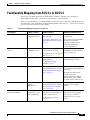
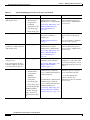
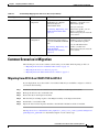
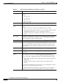
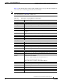
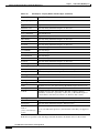
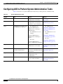
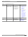
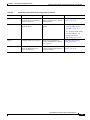
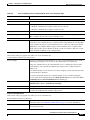
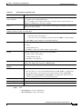
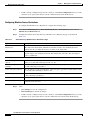
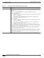
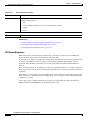
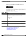
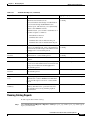
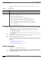
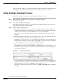
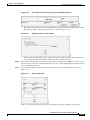
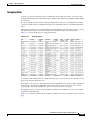
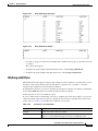
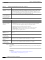
Functionality Mapping from ACS 4.x to ACS 5.4
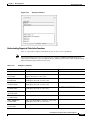
In ACS 5.4, you define authorizations, shell profiles, attributes, and other policy elements as
independent, reusable objects, and not as part of the user or group definition.
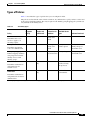
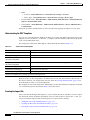
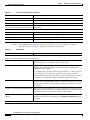
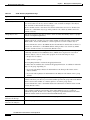
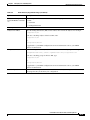
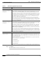
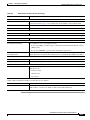
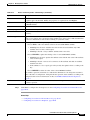
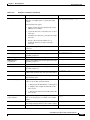
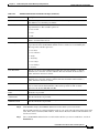
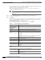
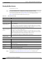
Table 2-1 describes where you configure identities, network resources, and policy elements in ACS 5.4.
Use this table to view and modify your migrated data identities. See Chapter 3, “ACS 5.x Policy Model”
for an overview of the ACS 5.4 policy model.
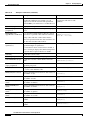
Table 2-1
Functionality Mapping from ACS 4.x to ACS 5.4
To configure...
In ACS 4.x, choose...
In ACS 5.4, choose...
Additional information for 5.4
Network device groups
Network
Configuration page
Network Resources > Network
Device Groups
You can use NDGs as conditions
in policy rules.
See Creating, Duplicating, and ACS 5.4 does not support NDG
Editing Network Device Groups, shared password. After
migration, member devices
page 7-2.
contain the NDG shared
password information.
Network devices and AAA
clients
Network
Configuration page
Network Resources > Network
Devices and AAA Clients
See Network Devices and AAA
Clients, page 7-5.
User groups
Group Setup page
Users and Identity Stores >
Identity Groups
RADIUS KeyWrap keys (KEK
and MACK) are migrated from
ACS 4.x to ACS 5.4.
You can use identity groups as
conditions in policy rules.
See Managing Identity
Attributes, page 8-7.
Internal users
User Setup page
Users and Identity Stores >
Internal Identity Stores > Users
See Managing Internal Identity
Stores, page 8-4.
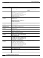
Internal hosts
Identity attributes
(user-defined fields)
Network Access
Profiles >
Authentication
Users and Identity Stores >
Internal Identity Stores > Hosts
Interface
Configuration > User
Data Configuration
System Administration >
Configuration > Dictionaries >
Identity > Internal Users
See Creating Hosts in Identity
Stores, page 8-16.
See Managing Dictionaries,
page 18-5.
ACS 5.4 authenticates internal
users against the internal identity
store only.
Migrated users that used an
external database for
authentication have a default
authentication password that
they must change on first access.
You can use the internal hosts in
identity policies for Host
Lookup.
Defined identity attribute fields
appear in the User Properties
page. You can use them as
conditions in access service
policies.
User Guide for Cisco Secure Access Control System 5.4
OL-26225-01
2-5
Chapter 2
Migrating from ACS 4.x to ACS 5.4
Functionality Mapping from ACS 4.x to ACS 5.4
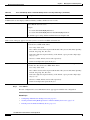
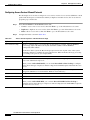
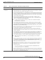
Table 2-1
Functionality Mapping from ACS 4.x to ACS 5.4 (continued)
To configure...
In ACS 4.x, choose...
In ACS 5.4, choose...
Command sets (command
authorization sets)
One of the following:
Policy Elements > Authorization You can add command sets as
results in authorization policy
and Permissions > Device
Administration > Command Set rules in a device administration
See Creating, Duplicating, and access service.
Shell exec parameters
Shell profiles (shell exec
parameters or shell command
authorization sets)
•
Shared Profile
Components >
Command
Authorization Set
•
User Setup page
•
Group Setup page
User Setup page
Group Setup page
Editing Command Sets for
Device Administration,
page 9-29.
System Administration >
Dictionaries > Identity >
Internal Users
Defined identity attribute fields
appear in the User Properties
page.
See Managing Dictionaries,
page 18-5.
You can use them as conditions
in access service policies.
Policy Elements > Authorization You can add shell profiles as
results in authorization policy
and Permissions > Device
rules in a device administration
Administration > Shell Profile
access service.
See Creating, Duplicating, and
Editing a Shell Profile for
Device Administration,
page 9-24.
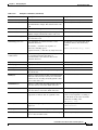
Date and time condition (Time Group Setup page
of Day Access)
Policy Elements > Session
Conditions > Date and Time
You cannot migrate the date
and time conditions. You have
to recreate them in ACS 5.4.
See Creating, Duplicating, and
Editing a Date and Time
Condition, page 9-3.
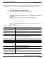
RADIUS Attributes
One of the following:
•
Shared Profile
Components >
RADIUS
Authorization
Component
Additional information for 5.4
Policy Elements > Authorization
and Permissions > Network
Access > Authorization Profile >
Common Tasks tab
You can add date and time
conditions to a policy rule in the
Service Selection policy or in an
authorization policy in an access
service.
You configure RADIUS
attributes as part of a network
access authorization profile.
You can add authorization
profiles as results in an
authorization policy in a network
Policy Elements > Authorization
access service.
and Permissions > Network
• User Setup page
Access > Authorization Profile >
• Group Setup page
RADIUS Attributes tab
You cannot migrate the
See Creating, Duplicating, and
RADIUS attributes
Editing Authorization Profiles
from user and group
for Network Access, page 9-18.
setups. You have to
recreate them in ACS
5.4.
or
User Guide for Cisco Secure Access Control System 5.4
2-6
OL-26225-01
Chapter 2
Migrating from ACS 4.x to ACS 5.4
Common Scenarios in Migration
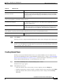
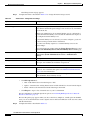
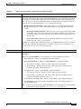
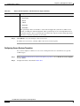
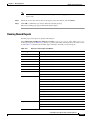
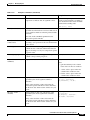
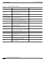
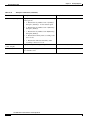
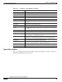
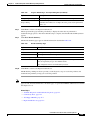
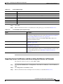
Table 2-1
Functionality Mapping from ACS 4.x to ACS 5.4 (continued)
To configure...
In ACS 4.x, choose...
In ACS 5.4, choose...
Additional information for 5.4
Downloadable ACLs
Shared Profile
Components
Policy Elements > Authorization
and Permissions > Named
Permission Objects >
Downloadable ACLs
You can add downloadable ACLs
(DACLs) to a network access
authorization profile.
See Creating, Duplicating, and
Editing Downloadable ACLs,
page 9-32.
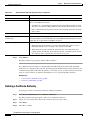
RADIUS VSA
Interface
Configuration
After you create the
authorization profile, you can
add it as a result in an
authorization policy in a network
access service.
You configure RADIUS VSA
System Administration >
Configuration > Dictionaries > attributes as part of a network
Protocols > RADIUS > RADIUS access authorization profile.
VSA.
You can add authorization
See Creating, Duplicating, and profiles as results in an
authorization policy in a network
Editing RADIUS
access service.
Vendor-Specific Attributes,
page 18-6.
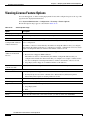
Common Scenarios in Migration
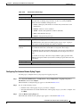
The following are some of the common scenarios that you encounter while migrating to ACS 5.4:
•
Migrating from ACS 4.2 on CSACS 1120 to ACS 5.4, page 2-7
•
Migrating from ACS 3.x to ACS 5.4, page 2-8
•
Migrating Data from Other AAA Servers to ACS 5.4, page 2-8
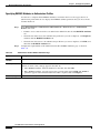
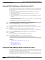
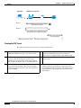
Migrating from ACS 4.2 on CSACS 1120 to ACS 5.4
In your deployment, if you have ACS 4.2 on CSACS 1120 and you would like to migrate to ACS 5.4,
you must do the following:
Step 1
Install Cisco Secure Access Control Server 4.2 for Windows on the migration machine.
Step 2
Back up the ACS 4.2 data on CSACS 1120.
Step 3
Restore the data in the migration machine.
Step 4
Run the Analysis and Export phase of the Migration utility on the migration machine.
Step 5
Install ACS 5.4 on CSACS 1120.
Step 6
Import the data from the migration machine to the CSACS 1120 that has ACS 5.4 installed.
See http://www.cisco.com/en/US/docs/net_mgmt/cisco_secure_access_control_system/5.4/migration/
guide/migration_guide.html for a detailed description of each of these steps.
User Guide for Cisco Secure Access Control System 5.4
OL-26225-01
2-7
Chapter 2
Migrating from ACS 4.x to ACS 5.4
Common Scenarios in Migration
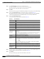
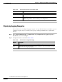
Migrating from ACS 3.x to ACS 5.4
If you have ACS 3.x deployed in your environment, you cannot directly migrate to ACS 5.4. You must
do the following:
Step 1
Upgrade to a migration-supported version of ACS 4.x. See Supported Migration Versions, page 2-2 for
a list of supported migration versions.
Step 2
Check the upgrade paths for ACS 3.x:
•
For the ACS Solution Engine, see:
http://www.cisco.com/en/US/docs/net_mgmt/
cisco_secure_access_control_server_for_solution_engine/4.1/installation/guide/solution_engine/
upgap.html#wp1120037
•
For ACS for Windows, see:
http://www.cisco.com/en/US/docs/net_mgmt/cisco_secure_access_control_server_for_windows/
4.2/installation/guide/windows/install.html#wp1102849
Step 3
Upgrade your ACS 3.x server to a migration-supported version of ACS 4.x.
After the upgrade, follow the steps that describe migrating from ACS 4.x to ACS 5.4. Refer to the
Migration Guide for Cisco Secure Access Control System 5.4 for more information.
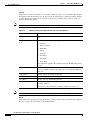
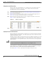
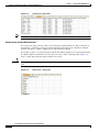
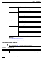
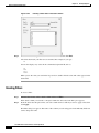
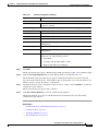
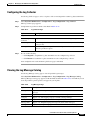
Migrating Data from Other AAA Servers to ACS 5.4
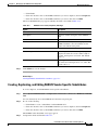
ACS 5.4 allows you to perform bulk import of various ACS objects through the ACS web interface and
the CLI. You can import the following ACS objects:
•
Users
•
Hosts
•
Network Devices
•
Identity Groups
•
NDGs
•
Downloadable ACLs
•
Command Sets
ACS allows you to perform bulk import of data with the use of a comma-separated values (.csv) file. You
must input data in the .csv file in the format that ACS requires. ACS provides a .csv template for the
various objects that you can import to ACS 5.4. You can download this template from the web interface.
To migrate data from other AAA servers to ACS 5.4:
Step 1
Input data into .csv files.
For more information on understanding .csv templates, see
http://www.cisco.com/en/US/docs/net_mgmt/cisco_secure_access_control_system/5.4/sdk/
cli_imp_exp.html#wp1064565.
Step 2
Set up your ACS 5.4 appliance.
User Guide for Cisco Secure Access Control System 5.4
2-8
OL-26225-01
Chapter 2
Migrating from ACS 4.x to ACS 5.4
Common Scenarios in Migration
Step 3
Perform bulk import of data into ACS 5.4.
For more information on performing bulk import of ACS objects, see
http://www.cisco.com/en/US/docs/net_mgmt/cisco_secure_access_control_system/5.4/sdk/
cli_imp_exp.html#wp1056244.
The data from your other AAA servers is now available in ACS 5.4.
User Guide for Cisco Secure Access Control System 5.4
OL-26225-01
2-9
Chapter 2
Migrating from ACS 4.x to ACS 5.4
Common Scenarios in Migration
User Guide for Cisco Secure Access Control System 5.4
2-10
OL-26225-01
CH A P T E R
3
ACS 5.x Policy Model
ACS 5.x is a policy-based access control system. The term policy model in ACS 5.x refers to the
presentation of policy elements, objects, and rules to the policy administrator. ACS 5.x uses a rule-based
policy model instead of the group-based model used in the 4.x versions.
This section contains the following topics:
Note
•
Overview of the ACS 5.x Policy Model, page 3-1
•
Access Services, page 3-6
•
Service Selection Policy, page 3-12
•
Authorization Profiles for Network Access, page 3-16
•
Policies and Identity Attributes, page 3-17
•
Policies and Network Device Groups, page 3-18
•
Example of a Rule-Based Policy, page 3-18
•
Flows for Configuring Services and Policies, page 3-19
See Functionality Mapping from ACS 4.x to ACS 5.4, page 2-5 for a mapping of ACS 4.x concepts to
ACS 5.4.
Overview of the ACS 5.x Policy Model
The ACS 5.x rule-based policy model provides more powerful and flexible access control than is
possible with the older group-based approach.
In the older group-based model, a group defines policy because it contains and ties together three types
of information:
•
Identity information—This information can be based on membership in AD or LDAP groups or a
static assignment for internal ACS users.
•
Other restrictions or conditions—Time restrictions, device restrictions, and so on.
•
Permissions—VLANs or Cisco IOS privilege levels.
The ACS 5.x policy model is based on rules of the form:
If condition then result
User Guide for Cisco Secure Access Control System 5.4
OL-26225-01
3-1
Chapter 3
ACS 5.x Policy Model
Overview of the ACS 5.x Policy Model
For example, we use the information described for the group-based model:
If identity-condition, restriction-condition then authorization-profile
In ACS 5.4, you define conditions and results as global, shared objects. You define them once and then
reference them when you create rules. ACS 5.4 uses the term policy elements for these shared objects,
and they are the building blocks for creating rules.
Table 3-1 shows how the various policy elements define all the information that the old group contained.
Table 3-1
Information in Policy Elements
Information in ACS 4.x Group
Identity information
Other policy conditions
Permissions
Information in ACS 5.4 Policy Element
•
AD group membership and attributes
•
LDAP group membership and attributes
•
ACS internal identity groups and attributes
•
Time and date conditions
•
Custom conditions
Authorization profiles
A policy is a set of rules that ACS 5.x uses to evaluate an access request and return a decision. For
example, the set of rules in an:
•
Authorization policy return the authorization decision for a given access request.
•
Identity policy decide how to authenticate and acquire identity attributes for a given access request.
ACS 5.x organizes the sequence of independent policies (a policy workflow) into an access service,
which it uses to process an access request. You can create multiple access services to process different
kinds of access requests; for example, for device administration or network access. For more
information, see Access Services, page 3-6.
You can define simple policies and rule-based policies. Rule-based policies are complex policies that
test various conditions. Simple policies apply a single result to all requests without any conditions.
There are various types of policies:
For more information on the different types of policies, see Types of Policies, page 3-5.
For more information about policy model terminology, see Policy Terminology, page 3-3.
Related Topics
•
Policies and Identity Attributes, page 3-17
•
Flows for Configuring Services and Policies, page 3-19
User Guide for Cisco Secure Access Control System 5.4
3-2
OL-26225-01
Chapter 3
ACS 5.x Policy Model
Overview of the ACS 5.x Policy Model
Policy Terminology
Table 3-2 describes the rule-based policy terminology.
Table 3-2
Rule-Based Policy Terminology
Term
Description
Access service
Sequential set of policies used to process access requests. ACS 5.x allows you to define multiple
access services to support multiple, independent, and isolated sets of policies on a single ACS
system.
There are two default access services: one for device administration (TACACS+ based access to the
device shell or CLI) and one for network access (RADIUS-based access to network connectivity).
Policy element
Global, shared object that defines policy conditions (for example, time and date, or custom
conditions based on user-selected attributes) and permissions (for example, authorization profiles).
The policy elements are referenced when you create policy rules.
Authorization profile
Basic permissions container for a RADIUS-based network access service, which is where you define
all permissions to be granted for a network access request.
VLANs, ACLs, URL redirects, session timeout or reauthorization timers, or any other RADIUS
attributes to be returned in a response, are defined in the authorization profile.
Shell profile
Basic permissions container for TACACS+ based device administration policy. This is where you
define permissions to be granted for a shell access request.
IOS privilege level, session timeout, and so on are defined in the shell profile.
Command set
Contains the set of permitted commands for TACACS+ based, per-command authorization.
Policy
Set of rules that are used to reach a specific policy decision. For example, how to authenticate and
what authorization to grant. For any policies that have a default rule, a policy is a first-match rules
table with a default rule for any request which does not match any user-created rules.
Identity policy
ACS 5.4 policy for choosing how to authenticate and acquire identity attributes for a given request.
ACS 5.4 allows two types of identity policies: a simple, static policy, or a rules-based policy for
more complex situations.
Identity group mapping Optional policy for mapping identity information collected from identity stores (for example, group
policy
memberships and user attributes) to a single ACS identity group.
This can help you normalize identity information and map requests to a single identity group, which
is just a tag or an identity classification. The identity group can be used as a condition in
authorization policy, if desired.
Authorization policy
ACS 5.4 policy for assigning authorization attributes for access requests. Authorization policy
selects a single rule and populates the response with the contents of the authorization profiles
referenced as the result of the rule.
Exception policy
Special option for authorization policy, which allows you to define separately the set of conditions
and authorization results for authorization policy exceptions and waivers. If defined, the exception
policy is checked before the main (standard) authorization policy.
Default rule
Catchall rule in ACS 5.4 policies. You can edit this rule to specify a default result or authorization
action, and it serves as the policy decision in cases where a given request fails to match the
conditions specified in any user-created rule.
User Guide for Cisco Secure Access Control System 5.4
OL-26225-01
3-3
Chapter 3
ACS 5.x Policy Model
Overview of the ACS 5.x Policy Model
Simple Policies
You can configure all of your ACS policies as rule-based policies. However, in some cases, you can
choose to configure a simple policy, which selects a single result to apply to all requests without
conditions.
For example, you can define a rule-based authentication policy with a set of rules for different
conditions; or, if you want to use the internal database for all authentications, you can define a simple
policy.
Table 3-3 helps you determine whether each policy type can be configured as a simple policy.
•
If you create and save a simple policy, and then change to a rule-based policy, the simple policy
becomes the default rule of the rule-based policy.
•
If you have saved a rule-based policy and then change to a simple policy, ACS automatically uses
the default rule as the simple policy.
Related Topic
•
Types of Policies, page 3-5
Rule-Based Policies
Rule-based policies have been introduced to overcome the challenges of identity-based policies. In
earlier versions of ACS, although membership in a user group gives members access permissions, it also
places certain restrictions on them.
When a user requests access, the user's credentials are authenticated using an identity store, and the user
is associated with the appropriate user group. Because authorization is tied to user group, all members
of a user group have the same access restrictions and permissions at all times.
With this type of policy (the simple policy), permissions are granted based on a user’s association with
a particular user group. This is useful if the user’s identity is the only dominant condition. However, for
users who need different permissions under different conditions, this policy does not work.
In ACS 5.x, you can create rules based on various conditions apart from identity. The user group no
longer contains all of the information.
For example, if you want to grant an employee full access while working on campus, and restricted
access while working remotely, you can do so using the rule-based policies in ACS 5.4.
You can base permissions on various conditions besides identity, and permissions are no longer
associated with user groups. You can use session and environment attributes, such as access location,
access type, health of the end station, date, time, and so on, to determine the type of access to be granted.
Authorization is now based on a set of rules:
If conditions then apply the respective permissions
With rule-based policies, conditions can consist of any combination of available session attributes, and
permissions are defined in authorization profiles. You define these authorization profiles to include
VLAN, downloadable ACLs, QoS settings, and RADIUS attributes.
User Guide for Cisco Secure Access Control System 5.4
3-4
OL-26225-01
Chapter 3
ACS 5.x Policy Model
Overview of the ACS 5.x Policy Model
Types of Policies
Table 3-3 describes the types of policies that you can configure in ACS.
The policies are listed in the order of their evaluation; any attributes that a policy retrieves can be used
in any policy listed subsequently. The only exception is the Identity group mapping policy, which uses
only attributes from identity stores.
Table 3-3
ACS Policy Types
Policy
Can Contain
Exception
Policy?
Simple1 and
Rule-Based?
Service Selection
No
Yes
No
Available Result
Types
Attributes Retrieved
All except
identity store
related
Access Service
—
Yes
All except
identity store
related
Identity Source,
Failure options
Identity Attributes;
Identity Group for
internal ID stores
No
Yes
Only identity
Identity Group
store dictionaries
Identity Group for
external ID stores
Yes
Rule-based
only
All dictionaries
Authorization
Profile, Security
Group Access
—
Yes
Rule-based
only
All dictionaries
Shell Profile,
Command Set
—
Determines the access
service to apply to an
incoming request.
Identity
Determines the identity
source for authentication.
Identity Group Mapping
Defines mapping attributes
and groups from external
identity stores to ACS
identity groups.
Network Access Authorization
Determines authorization
and permissions for
network access.
Device Administration
Authorization
Available
Dictionaries for
Conditions
Determines authorization
and permissions for device
administration.
1. A simple policy specifies a single set of results that ACS applies to all requests; it is in effect a one-rule policy.
User Guide for Cisco Secure Access Control System 5.4
OL-26225-01
3-5
Chapter 3
ACS 5.x Policy Model
Access Services
Access Services
Access services are fundamental constructs in ACS 5.x that allow you to configure access policies for
users and devices that connect to the network and for network administrators who administer network
devices.
In ACS 5.x, authentication and authorization requests are processed by access services. An access
service consists of the following elements:
•
Identity Policy—Specifies how the user should be authenticated and includes the allowed
authentication protocols and the user repository to use for password validation.
•
Group Mapping Policy—Specifies if the user's ACS identity group should be dynamically
established based on user attributes or group membership in external identity stores. The user's
identity group can be used as part of their authorization.
•
Authorization Policy—Specifies the authorization rules for the user.
The access service is an independent set of policies used to process an access request.
The ACS administrator might choose to create multiple access services to allow clean separation and
isolation for processing different kinds of access requests. ACS provides two default access services:
•
Default Device Admin—Used for TACACS+ based access to device CLI
•
Default Network Access—Used for RADIUS-based access to network connectivity
You can use the access services as is, modify them, or delete them as needed. You can also create
additional access services.
The TACACS+ protocol separates authentication from authorization; ACS processes TACACS+
authentication and authorization requests separately. Table 3-4 describes additional differences between
RADIUS and TACACS+ access services.
Table 3-4
Differences Between RADIUS and TACACS+ Access Services
Policy Type
TACACS+
RADIUS
Identity
Optional1
Required
Group Mapping
Optional
Optional
Authorization
Optional
1
Required
1. For TACACS+, you must select either Identity or Authorization.
For TACACS+, all policy types are optional; however, you must choose at least one policy type in a
service. If you do not define an identity policy for TACACS+, ACS returns authentication failed for an
authentication request.
Similarly, if you do not define an authorization policy and if ACS receives a session or command
authorization request, it fails. For both RADIUS and TACACS+ access services, you can modify the
service to add policies after creation.
Note
Access services do not contain the service selection policy. Service selection rules are defined
independently.
You can maintain and manage multiple access services; for example, for different use cases, networks,
regions, or administrative domains. You configure a service selection policy, which is a set of service
selection rules to direct each new access request to the appropriate access service.
User Guide for Cisco Secure Access Control System 5.4
3-6
OL-26225-01
Chapter 3
ACS 5.x Policy Model
Access Services
Table 3-5 describes an example of a set of access services.
Table 3-5
Access Service List
Access Service A
for Device Administration
Access Service B
for Access to 802.1X Agentless
Hosts
Access Service C
for Access from 802.1X Wired and
Wireless Devices
Identity Policy A
Identity Policy B
Identity Policy C
Shell/Command Authorization
Policy A
Session Authorization Policy B Session Authorization Policy C
Table 3-6 describes a service selection policy.
Table 3-6
Service Selection Policy
Rule Name
Condition
Result
DevAdmin
protocol = TACACS+
Access Service A
Agentless
Host Lookup = True
Access Service C
Default
—
Access Service B
If ACS 5.4 receives a TACACS+ access request, it applies Access Service A, which authenticates the
request according to Identity Policy A. It then applies authorizations and permissions according to the
shell/command authorization policy. This service handles all TACACS+ requests.
If ACS 5.4 receives a RADIUS request that it determines is a host lookup (for example, the RADIUS
service-type attribute is equal to call-check), it applies Access Service C, which authenticates according
to Identity Policy C. It then applies a session authorization profile according to Session Authorization
Policy C. This service handles all host lookup requests (also known as MAC Auth Bypass requests).
Access Service B handles other RADIUS requests. This access service authenticates according to
Identity Policy B and applies Session Authorization Policy B. This service handles all RADIUS requests
except for host lookups, which are handled by the previous rule.
Access Service Templates
ACS contains predefined access services that you can use as a template when creating a new service.
When you choose an access service template, ACS creates an access service that contains a set of
policies, each with a customized set of conditions.
You can change the structure of the access service by adding or removing a policy from the service, and
you can change the structure of a policy by modifying the set of policy conditions. See Configuring
Access Services Templates, page 10-20, for a list of the access service templates and descriptions.
RADIUS and TACACS+ Proxy Services
ACS 5.4 can function as a RADIUS, RADIUS proxy or TACACS+ proxy server.
•
As a RADIUS proxy server, ACS receives authentication and accounting requests from the NAS and
forwards the requests to the external RADIUS server.
•
As a TACACS+ proxy server, ACS receives authentication, authorization and accounting requests
from the NAS and forwards the requests to the external TACACS+ server.
User Guide for Cisco Secure Access Control System 5.4
OL-26225-01
3-7
Chapter 3
ACS 5.x Policy Model
Access Services
ACS accepts the results of the requests and returns them to the NAS. You must configure the external
RADIUS and TACACS+ servers in ACS for ACS to forward requests to them. You can define the timeout
period and the number of connection attempts.
The ACS proxy remote target is a list of remote RADIUS and TACACS+ servers that contain the
following parameters:
•
IP
•
Authentication port
•
Accounting port
•
Shared secret
•
Reply timeout
•
Number of retries
•
Connection port
•
Network timeout
The following information is available in the proxy service:
•
Remote RADIUS or TACACS+ servers list
•
Accounting proxy local/remote/both
•
Strip username prefix/suffix
When a RADIUS proxy server receives a request, it forwards it to the first remote RADIUS or TACACS+
server in the list. If the proxy server does not receive a response within the specified timeout interval and
the specified number of retries, it forwards the request to the next RADIUS or TACACS+ server in the
list.
When the first response arrives from any of the remote RADIUS or TACACS+ servers in the list, the
proxy service processes it. If the response is valid, ACS sends the response back to the NAS.
Table 3-7 lists the differences in RADIUS proxy service between ACS 4.2 and 5.4 releases.
Table 3-7
Differences in RADIUS and TACACS+ Proxy Service Between ACS 4.2 and 5.4
Feature
ACS 5.4
ACS 4.2
Configurable timeout (RADIUS)
Yes
No
Configurable retry count (RADIUS)
Yes
No
Network timeout (TACACS+)
Yes
No
Authentication and accounting ports
(RADIUS)
Yes
Yes
Connection port (TACACS+)
Yes
No
Proxy cycles detection
Yes (For RADIUS only)
No
Username stripping
Yes
Yes
Accounting proxy (local, remote, or both)
Yes
Yes
Account delay timeout support (RADIUS)
No
No
User Guide for Cisco Secure Access Control System 5.4
3-8
OL-26225-01
Chapter 3
ACS 5.x Policy Model
Access Services
ACS can simultaneously act as a proxy server to multiple external RADIUS and TACACS+ servers. For
ACS to act as a proxy server, you must configure a RADIUS or TACACS+ proxy service in ACS. See
Configuring General Access Service Properties, page 10-13 for information on how to configure a
RADIUS proxy service.
For more information on proxying RADIUS and TACACS+ requests, see RADIUS and TACACS+ Proxy
Requests, page 4-29.
Related Topics
•
Policy Terminology, page 3-3
•
Types of Policies, page 3-5
•
Flows for Configuring Services and Policies, page 3-19
Identity Policy
Two primary mechanisms define the mechanism and source used to authenticate requests:
•
Password-based—Authentication is performed against databases after the user enters a username
and password. Hosts can bypass this authentication by specifying a MAC address. However, for
identity policy authentication, host lookup is also considered to be password-based.
•
Certificate-based—A client presents a certificate for authentication of the session. In ACS 5.4,
certificate-based authentication occurs when the PEAP-TLS or EAP-TLS protocol is selected.
In addition, databases can be used to retrieve attributes for the principal in the request.
The identity source is one result of the identity policy and can be one of the following types:
•
Deny Access—Access to the user is denied and no authentication is performed.
•
Identity Database—Single identity database. When a single identity database is selected as the result
of the identity policy, either an external database (LDAP or AD) or an internal database (users or
hosts) is selected as the result.
The database selected is used to authenticate the user/host and to retrieve any defined attributes
stored for the user/host in the database.
•
Certificate Authentication Profile—Contains information about the structure and content of the
certificate, and specifically maps certificate attribute to internal username. For certificate-based
authentication, you must select a certificate authentication profile.
For certificate based requests, the entity which identifies itself with a certificate holds the private
key that correlates to the public key stored in the certificate. The certificate authentication profile
extends the basic PKI processing by defining the following:
– The certificate attribute used to define the username. You can select a subset of the certificate
attributes to populate the username field for the context of the request. The username is then
used to identify the user for the remainder of the request, including the identification used in the
logs.
– The LDAP or AD database to use to verify the revocation status of the certificate. When you
select an LDAP or AD database, the certificate data is retrieved from the LDAP or AD database
and compared against the data entered by the client in order to provide additional verification
of the client certificate.
User Guide for Cisco Secure Access Control System 5.4
OL-26225-01
3-9
Chapter 3
ACS 5.x Policy Model
Access Services
•
Identity Sequence—Sequences of the identity databases. The sequence is used for authentication
and, if specified, an additional sequence is used to retrieve only attributes. You can select multiple
identity methods as the result of the identity policy. You define the identity methods in an identity
sequence object, and the methods included within the sequence may be of any type.
There are two components to an identity sequence: one for authentication, and one for attribute
retrieval. The administrator can select to perform authentication based on a certificate or an identity
database or both.
– If you choose to perform authentication based on a certificate, ACS selects a single certificate
authentication profile.
– If you choose to perform authentication based on an identity database, you must define a list of
databases to be accessed in sequence until authentication succeeds. When authentication
succeeds, any defined attributes within the database are retrieved.
In addition, you can define an optional list of databases from which additional attributes are
retrieved. These additional databases can be accessed irrespective of whether password- or
certificate-based authentication was used.
When certificate-based authentication is used, the username field is populated from a certificate
attribute and is used to retrieve attributes. All databases defined in the list are accessed and, in cases
where a matching record for the user is found, the corresponding attributes, are retrieved.
Attributes can be retrieved for a user even if the user’s password is marked that it needs to be
changed or if the user account is disabled. Even when you disable a user’s account, the user’s
attributes are still available as a source of attributes, but not for authentication.
Failure Options
If a failure occurs while processing the identity policy, the failure can be one of three main types:
•
Authentication failed—ACS received an explicit response that the authentication failed. For
example, the wrong username or password was entered, or the user was disabled.
•
User/host not found—No such user/host was found in any of the authentication databases.
•
Process failed—There was a failure while accessing the defined databases.
All failures returned from an identity database are placed into one of the types above. For each type of
failure, you can configure the following options:
•
Reject—ACS sends a reject reply.
•
Drop—No reply is returned.
•
Continue—ACS continues processing to the next defined policy in the service.
The Authentication Status system attribute retains the result of the identity policy processing. If you
select to continue policy processing in the case of a failure, this attribute can be referred to as a condition
in subsequent policy processing to distinguish cases in which identity policy processing did not succeed.
Because of restrictions on the underlying protocol being used, there are cases in which it is not possible
to continue processing even if you select the Continue option. This is the case for PEAP, LEAP, and
EAP-FAST; even if you select the Continue option, the request is rejected.
The following default values are used for the failure options when you create rules:
•
Authentication failed—The default is reject.
•
User/host not found—The default is reject.
•
Process failure—The default is drop.
User Guide for Cisco Secure Access Control System 5.4
3-10
OL-26225-01
Chapter 3
ACS 5.x Policy Model
Access Services
Group Mapping Policy
The identity group mapping policy is a standard policy. Conditions can be based on attributes or groups
retrieved from the external attribute stores only, or from certificates, and the result is an identity group
within the identity group hierarchy.
If the identity policy accesses the internal user or host identity store, then the identity group is set directly
from the corresponding user or host record. This processing is an implicit part of the group mapping
policy.
Therefore, as part of processing in the group mapping policy, the default rule is only applied if both of
the following conditions are true:
•
None of the rules in the group mapping table match.
•
The identity group is not set from the internal user or host record.
The results of the group mapping policy are stored in the IdentityGroup attribute in the System
Dictionary and you can include this attribute in policies by selecting the Identity Group condition.
Authorization Policy for Device Administration
Shell profiles determine access to the device CLI; command sets determine TACACS+ per command
authorization. The authorization policy for a device administration access service can contain a single
shell profile and multiple command sets.
Processing Rules with Multiple Command Sets
It is important to understand how ACS processes the command in the access request when the
authorization policy includes rules with multiple command sets. When a rule result contains multiple
command sets, and the rule conditions match the access request, ACS processes the command in the
access request against each command set in the rule:
1.
If a command set contains a match for the command and its arguments, and the match has Deny
Always, ACS designates the command set as Commandset-DenyAlways.
2.
If there is no Deny Always for a command match in a command set, ACS checks all the commands
in the command set sequentially for the first match.
– If the first match has Permit, ACS designates the command set as Commandset-Permit.
– If the first match has Deny, ACS designates the command set as Commandset-Deny.
3.
If there is no match and “Permit any command that is not in the table below” is not checked (default,)
ACS designates the command set as Commandset-Deny.
4.
If there is no match and “Permit any command that is not in the table below” is checked, ACS
designates the command set as Commandset-Permit.
5.
After ACS has analyzed all the command sets, it authorizes the command:
a. If ACS designated any command set as Commandset-DenyAlways, ACS denies the command.
b. If there is no Commandset-DenyAlways, ACS permits the command if any command set is
Commandset-Permit; otherwise, ACS denies the command.
User Guide for Cisco Secure Access Control System 5.4
OL-26225-01
3-11
Chapter 3
ACS 5.x Policy Model
Service Selection Policy
Related Topics
•
Policy Terminology, page 3-3
•
Authorization Profiles for Network Access, page 3-16
Exception Authorization Policy Rules
A common real-world problem is that, in day-to-day operations, you often need to grant policy waivers
or policy exceptions. A specific user might need special access for a short period of time; or, a user might
require some additional user permissions to cover for someone else who is on vacation.
In ACS, you can define an exception policy for an authorization policy. The exception policy contains a
separate set of rules for policy exception and waivers, which are typically ad hoc and temporary. The
exception rules override the rules in the main rule table.
The exception rules can use a different set of conditions and results from those in the main policy. For
example, the main policy might use Identity Group and Location as its conditions, while its related
exception policy might use different conditions
By default, exception policies use a compound condition and a time and date condition. The time and
date condition is particularly valuable if you want to make sure your exception rules have a definite
starting and ending time.
An exception policy takes priority over the main policy. The exception policy does not require its own
default rule; if there is no match in the exception policy, the main policy applies, which has its own
default rule.
You can use an exception to address a temporary change to a standard policy. For example, if an
administrator, John, in one group is on vacation, and an administrator, Bob, from another group is
covering for him, you can create an exception rule that will give Bob the same access permissions as
John for the vacation period.
Related Topics
•
Policy Terminology, page 3-3
•
Policy Conditions, page 3-16
•
Policy Results, page 3-16
•
Policies and Identity Attributes, page 3-17
Service Selection Policy
When ACS receives various access requests, it uses a service selection policy to process the request. ACS
provides you two modes of service selection:
•
Simple Service Selection, page 3-12
•
Rules-Based Service Selection, page 3-13
Simple Service Selection
In the simple service selection mode, ACS processes all AAA requests with just one access service and
does not actually select a service.
User Guide for Cisco Secure Access Control System 5.4
3-12
OL-26225-01
Chapter 3
ACS 5.x Policy Model
Service Selection Policy
Rules-Based Service Selection
In the rules-based service selection mode, ACS decides which access service to use based on various
configurable options. Some of them are:
•
AAA Protocol—The protocol used for the request, TACACS+ or RADIUS.
•
Request Attributes—RADIUS or TACACS+ attributes in the request.
•
Date and Time—The date and time ACS receives the request.
•
Network Device Group—The network device group that the AAA client belongs to.
•
ACS Server—The ACS server that receives this request.
•
AAA Client—The AAA client that sent the request.
•
Network condition objects—The network conditions can be based on
– End Station—End stations that initiate and terminate connections.
– Device—The AAA client that processes the request.
– Device Port—In addition to the device, this condition also checks for the port to which the end
station is associated with.
For more information on policy conditions, see Managing Policy Conditions, page 9-1.
ACS comes preconfigured with two default access services: Default Device Admin and Default Network
Access. The rules-based service selection mode is configured to use the AAA protocol as the selection
criterion and hence when a TACACS+ request comes in, the Default Device Admin service is used and
when a RADIUS request comes in, the Default Network Access service is used.
Access Services and Service Selection Scenarios
ACS allows an organization to manage its identity and access control requirements for multiple
scenarios, such as wired, wireless, remote VPN, and device administration. The access services play a
major role in supporting these different scenarios.
Access services allow the creation of distinct and separate network access policies to address the unique
policy requirements of different network access scenarios. With distinct policies for different scenarios,
you can better manage your organization's network.
For example, the default access services for device administration and network access reflect the typical
distinction in policy that is required for network administrators accessing network devices and an
organization's staff accessing the company’s network.
However, you can create multiple access services to distinguish the different administrative domains. For
example, wireless access in the Asia Pacific regions can be administered by a different team than the one
that manages wireless access for European users. This situation calls for the following access services:
•
APAC-wireless—Access service for wireless users in the Asia Pacific region.
•
Europe-wireless—Access service for wireless users in the European countries.
You can create additional access services to reduce complexity in policies within a single access service
by creating the complex policy among multiple access services. For example, if a large organization
wishes to deploy 802.1x network access, it can have the following access services:
•
802.1x—For machine, user password, and certificate-based authentication for permanent staff.
•
Agentless Devices—For devices that do not have an EAP supplicant, such as phones and printers.
•
Guest Access—For users accessing guest wireless networks.
User Guide for Cisco Secure Access Control System 5.4
OL-26225-01
3-13
Chapter 3
ACS 5.x Policy Model
Service Selection Policy
In this example, instead of creating the network access policy for 802.1x, agentless devices, and guest
access in one access service, the policy is divided into three access services.
First-Match Rule Tables
ACS 5.4 provides policy decisions by using first-match rule tables to evaluate a set of rules. Rule tables
contain conditions and results. Conditions can be either simple or compound. Simple conditions consist
of attribute operator value and are either True or False. Compound conditions contain more complex
conditions combined with AND or OR operators. See Policy Conditions, page 3-16 for more
information.
The administrator selects simple conditions to be included in a policy. The conditions are displayed as
columns in a rule table where the column headings are the condition name, which is usually the name of
the attribute.
The rules are displayed under the column headings, and each cell indicates the operator and value that
are combined with the attribute to form the condition. If ANY Figure 3-1 shows a column-based rule table
with defined condition types.
Figure 3-1
Example Policy Rule Table
User Guide for Cisco Secure Access Control System 5.4
3-14
OL-26225-01
Chapter 3
ACS 5.x Policy Model
Service Selection Policy
Column
Description
Status
You can define the status of a rule as enabled, disabled, or monitored:
•
Enabled—ACS evaluates an enabled rule, and when the rule conditions match the access request,
ACS applies the rule result.
•
Disabled—The rule appears in the rule table, but ACS skips this rule and does not evaluate it.
•
Monitor Only—ACS evaluates a monitored rule. If the rule conditions match the access request, ACS
creates a log record with information relating to the match.
ACS does not apply the result, and the processing continues to the following rules. Use this status
during a running-in period for a rule to see whether it is needed.
Name
Descriptive name. You can specify any name that describes the rule’s purpose. By default, ACS generates
rule name strings rule-number.
Conditions
Identity Group
In this example, this is matching against one of the internal identity groups.
NDG: Location
Location network device group. The two predefined NDGs are Location and Device Type.
Results
Shell Profile
Used for device administration-type policies and contains permissions for TACACS+ shell access request,
such as Cisco IOS privilege level.
Hit Counts
Displays the number of times a rule matched an incoming request since the last reset of the policy’s hit
counters. ACS counts hits for any monitored or enabled rule whose conditions all matched an incoming
request. Hit counts for:
•
Enabled rules reflect the matches that occur when ACS processes requests.
•
Monitored rules reflect the counts that would result for these rules if they were enabled when ACS
processed the requests.
The primary server in an ACS deployment displays the hit counts, which represent the total matches for
each rule across all servers in the deployment. On a secondary server, all hit counts in policy tables appear
as zeroes.
The default rule specifies the policy result that ACS uses when no other rules exist, or when the attribute
values in the access request do not match any rules.
ACS evaluates a set of rules in the first-match rule table by comparing the values of the attributes
associated with the current access request with a set of conditions expressed in a rule.
•
If the attribute values do not match the conditions, ACS proceeds to the next rule in the rule table.
•
If the attribute values match the conditions, ACS applies the result that is specified for that rule, and
ignores all remaining rules.
•
If the attribute values do not match any of the conditions, ACS applies the result that is specified for
the policy default rule.
Related Topics
•
Policy Terminology, page 3-3
•
Policy Conditions, page 3-16
•
Policy Results, page 3-16
•
Exception Authorization Policy Rules, page 3-12
User Guide for Cisco Secure Access Control System 5.4
OL-26225-01
3-15
Chapter 3
ACS 5.x Policy Model
Authorization Profiles for Network Access
Policy Conditions
You can define simple conditions in rule tables based on attributes in:
•
Customizable conditions—You can create custom conditions based on protocol dictionaries and
identity dictionaries that ACS knows about. You define custom conditions in a policy rule page; you
cannot define them as separate condition objects.
•
Standard conditions—You can use standard conditions, which are based on attributes that are always
available, such as device IP address, protocol, and username-related fields.
Related Topics
•
Policy Terminology, page 3-3
•
Policy Results, page 3-16
•
Exception Authorization Policy Rules, page 3-12
•
Policies and Identity Attributes, page 3-17
Policy Results
Policy rules include result information depending on the type of policy. You define policy results as
independent shared objects; they are not related to user or user group definitions.
For example, the policy elements that define authorization and permission results for authorization
policies include:
•
Identity source and failure options as results for identity policies. See Authorization Profiles for
Network Access, page 3-16.
•
Identity groups for group mapping. See Group Mapping Policy, page 3-11.
•
Authorization Profiles for Network Access, page 3-16.
•
Authorization Policy for Device Administration, page 3-11.
•
Security groups and security group access control lists (ACLs) for Cisco Security Group Access.
See ACS and Cisco Security Group Access, page 4-23.
For additional policy results, see Managing Authorizations and Permissions, page 9-17.
Related Topics
•
Policy Terminology, page 3-3
•
Policy Conditions, page 3-16
•
Exception Authorization Policy Rules, page 3-12
•
Policies and Identity Attributes, page 3-17
Authorization Profiles for Network Access
Authorization profiles define the set of RADIUS attributes that ACS returns to a user after successful
authorization. The access authorization information includes authorization privileges and permissions,
and other information such as downloadable ACLs.
User Guide for Cisco Secure Access Control System 5.4
3-16
OL-26225-01
Chapter 3
ACS 5.x Policy Model
Policies and Identity Attributes
You can define multiple authorization profiles as a network access policy result. In this way, you
maintain a smaller number of authorization profiles, because you can use the authorization profiles in
combination as rule results, rather than maintaining all the combinations themselves in individual
profiles.
Processing Rules with Multiple Authorization Profiles
A session authorization policy can contain rules with multiple authorization profiles. The authorization
profile contains general information (name and description) and RADIUS attributes only. When you use
multiple authorization profiles, ACS merges these profiles into a single set of attributes. If a specific
attribute appears:
•
In only one of the resulting authorization profiles, it is included in the authorization result.
•
Multiple times in the result profiles, ACS determines the attribute value for the authorization result
based on the attribute value in the profile that appears first in the result set.
For example, if a VLAN appears in the first profile, that takes precedence over a VLAN that appears
in a 2nd or 3rd profile in the list.
Note
If you are using multiple authorization profiles, make sure you order them in priority order.
The RADIUS attribute definitions in the protocol dictionary specify whether the attribute can appear
only once in the response, or multiple times. In either case, ACS takes the values for any attribute from
only one profile, irrespective of the number of times the values appear in the response. The only
exception is the Cisco attribute value (AV) pair, which ACS takes from all profiles included in the result.
Related Topics
•
Policy Terminology, page 3-3
•
Authorization Policy for Device Administration, page 3-11
Policies and Identity Attributes
The identity stores contain identity attributes that you can use as part of policy conditions and in
authorization results. When you create a policy, you can reference the identity attributes and user
attributes.
This gives you more flexibility in mapping groups directly to permissions in authorization rules. When
ACS processes a request for a user or host, the identity attributes are retrieved and can then be used in
authorization policy conditions.
For example, if you are using the ACS internal users identity store, you can reference the identity group
of the internal user or you can reference attributes of the internal user. (Note that ACS allows you to
create additional custom attributes for the internal identity store records.)
If you are using an external Active Directory (AD), you can reference AD groups directly in
authorization rules, and you can also reference AD user attributes directly in authorization rules. User
attributes might include a user’s department or manager attribute.
User Guide for Cisco Secure Access Control System 5.4
OL-26225-01
3-17
Chapter 3
ACS 5.x Policy Model
Policies and Network Device Groups
Related Topics
•
Managing Users and Identity Stores, page 8-1
•
Policy Terminology, page 3-3
•
Types of Policies, page 3-5
Policies and Network Device Groups
You can reference Network device groups (NDGs) as policy conditions. When the ACS receives a
request for a device, the NDGs associated with that device are retrieved and compared against those in
the policy table. With this method, you can group multiple devices and assign them the same policies.
For example, you can group all devices in a specific location together and assign to them the same policy.
When ACS receives a request from a network device to access the network, it searches the network
device repository to find an entry with a matching IP address. When a request arrives from a device that
ACS identified using the IP address, ACS retrieves all NDGs associated with the device.
Related Topics
•
Managing Users and Identity Stores, page 8-1
•
Policy Terminology, page 3-3
•
Types of Policies, page 3-5
Example of a Rule-Based Policy
The following example illustrates how you can use policy elements to create policy rules.
A company divides its network into two regions, East and West, with network operations engineers at
each site. They want to create an access policy that allows engineers:
•
Full access to the network devices in their region.
•
Read-only access to devices outside their region.
You can use the ACS 5.4 policy model to:
•
Define East and West network device groups, and map network devices to the appropriate group.
•
Define East and West identity groups, and map users (network engineers) to the appropriate group.
•
Define Full Access and Read Only authorization profiles.
•
Define Rules that allow each identity group full access or read-only access, depending on the
network device group location.
Previously, you had to create two user groups, one for each location of engineers, each with separate
definitions for permissions, and so on. This definition would not provide the same amount of flexibility
and granularity as in the rule-based model.
User Guide for Cisco Secure Access Control System 5.4
3-18
OL-26225-01
Chapter 3
ACS 5.x Policy Model
Flows for Configuring Services and Policies
Figure 3-2 illustrates what this policy rule table could look like.
Figure 3-2
Sample Rule-Based Policy
Each row in the policy table represents a single rule.
Each rule, except for the last Default rule, contains two conditions, ID Group and Location, and a result,
Authorization Profile. ID Group is an identity-based classification and Location is a nonidentity
condition. The authorization profiles contain permissions for a session.
The ID Group, Location, and Authorization Profile are the policy elements.
Related Topics
•
Policy Terminology, page 3-3
•
Types of Policies, page 3-5
•
Access Services, page 3-6
•
Flows for Configuring Services and Policies, page 3-19
Flows for Configuring Services and Policies
Table 3-8 describes the recommended basic flow for configuring services and policies; this flow does
not include user-defined conditions and attribute configurations. With this flow, you can use NDGs,
identity groups, and compound conditions in rules.
Prerequisites
Before you configure services and policies, it is assumed you have done the following:
•
Added network resources to ACS and create network device groups. See Creating, Duplicating, and
Editing Network Device Groups, page 7-2 and Network Devices and AAA Clients, page 7-5.
User Guide for Cisco Secure Access Control System 5.4
OL-26225-01
3-19
Chapter 3
ACS 5.x Policy Model
Flows for Configuring Services and Policies
•
Table 3-8
Added users to the internal ACS identity store or add external identity stores. See Creating Internal
Users, page 8-11, Managing Identity Attributes, page 8-7, or Creating External LDAP Identity
Stores, page 8-26.
Steps to Configure Services and Policies
Step
Action
Drawer in Web Interface
Step 1
Define policy results:
Policy Elements
•
Authorizations and permissions for device administration—Shell
profiles or command sets.
•
Authorizations and permissions for network access—Authorization
profile.
See:
•
Creating, Duplicating, and Editing a Shell Profile for Device
Administration, page 9-24
•
Creating, Duplicating, and Editing Command Sets for Device
Administration, page 9-29
•
Creating, Duplicating, and Editing Authorization Profiles for Network
Access, page 9-18
Step 2
(Optional) Define custom conditions to policy rules. You can complete this —
step before defining policy rules in Step 6, or you can define custom
conditions while in the process of creating a rule. SeeCreating, Duplicating,
and Editing a Custom Session Condition, page 9-5.
Step 3
Create Access Services—Define only the structure and allowed protocols;
you do not need to define the policies yet. See Creating, Duplicating, and
Editing Access Services, page 10-12.
Access Policies
Step 4
Add rules to Service Selection Policy to determine which access service to
use for requests. See:
Access Policies
•
Customizing a Policy, page 10-4
•
Creating, Duplicating, and Editing Service Selection Rules, page 10-8
Step 5
Define identity policy. Select the identity store or sequence you want to use Users and Identity Stores
to authenticate requests and obtain identity attributes. See Managing Users
and Identity Stores.
Step 6
Create authorization rules:
•
Device administration—Shell/command authorization policy.
•
Network access—Session authorization policy.
Access Policies
See:
•
Customizing a Policy, page 10-4
•
Configuring Access Service Policies, page 10-22
User Guide for Cisco Secure Access Control System 5.4
3-20
OL-26225-01
Chapter 3
ACS 5.x Policy Model
Flows for Configuring Services and Policies
Related Topics
•
Policy Terminology, page 3-3
•
Policy Conditions, page 3-16
•
Policy Results, page 3-16
•
Policies and Identity Attributes, page 3-17
User Guide for Cisco Secure Access Control System 5.4
OL-26225-01
3-21
Chapter 3
ACS 5.x Policy Model
Flows for Configuring Services and Policies
User Guide for Cisco Secure Access Control System 5.4
3-22
OL-26225-01
CH A P T E R
4
Common Scenarios Using ACS
Network control refers to the process of controlling access to a network. Traditionally a username and
password was used to authenticate a user to a network. Now a days with the rapid technological
advancements, the traditional method of managing network access with a username and a password is
no longer sufficient.
The ways in which the users can access the network and what they can access have changed considerably.
Hence, you must define complex and dynamic policies to control access to your network.
For example, earlier, a user was granted access to a network and authorized to perform certain actions
based on the group that the user belonged to. Now, in addition to the group that the user belongs to, you
must also consider other factors, such as whether:
•
The user is trying to gain access within or outside of work hours.
•
The user is attempting to gain access remotely.
•
The user has full or restricted access to the services and resources.
Apart from users, you also have devices that attempt to connect to your network.
When users and devices try to connect to your network through network access servers, such as wireless
access points, 802.1x switches, and VPN servers, ACS authenticates and authorizes the request before a
connection is established.
Authentication is the process of verifying the identity of the user or device that attempts to connect to a
network. ACS receives identity proof from the user or device in the form of credentials. There are two
different authentication methods:
•
Password-based authentication—A simpler and easier way of authenticating users. The user enters
a username and password. The server checks for the username and password in its internal or
external databases and if found, grants access to the user. The level of access (authorization) is
defined by the rules and conditions that you have created.
•
Certificate-based authentication—ACS supports certificate-based authentication with the use of the
Extensible Authentication Protocol-Transport Level Security (EAP-TLS) and Protected Extensible
Authentication Protocol-Transport Level Security (PEAP-TLS), which uses certificates for server
authentication by the client and for client authentication by the server.
Certificate-based authentication methods provide stronger security and are recommended when
compared to password-based authentication methods.
Authorization determines the level of access that is granted to the user or device. The rule-based policy
model in ACS 5.x allows you to define complex conditions in rules. ACS uses a set of rules (policy) to
evaluate an access request and to return a decision.
User Guide for Cisco Secure Access Control System 5.4
OL-26225-01
4-1
Chapter 4
Common Scenarios Using ACS
Overview of Device Administration
ACS organizes a sequence of independent policies into an access service, which is used to process an
access request. You can create multiple access services to process different kinds of access requests; for
example, for device administration or network access.
Cisco Secure Access Control System (ACS) allows you to centrally manage access to your network
services and resources (including devices, such as IP phones, printers, and so on). ACS 5.4 is a
policy-based access control system that allows you to create complex policy conditions and helps you to
comply with the various Governmental regulations.
When you deploy ACS in your network, you must choose an appropriate authentication method that
determines access to your network.
This chapter provides guidelines for some of the common scenarios. This chapter contains:
•
Overview of Device Administration, page 4-2
•
Password-Based Network Access, page 4-5
•
Certificate-Based Network Access, page 4-9
•
Agentless Network Access, page 4-12
•
VPN Remote Network Access, page 4-20
•
ACS and Cisco Security Group Access, page 4-23
•
RADIUS and TACACS+ Proxy Requests, page 4-29
Overview of Device Administration
Device administration allows ACS to control and audit the administration operations performed on
network devices, by using these methods:
•
Session administration—A session authorization request to a network device elicits an ACS
response. The response includes a token that is interpreted by the network device which limits the
commands that may be executed for the duration of a session. See Session Administration, page 4-3.
•
Command authorization—When an administrator issues operational commands on a network
device, ACS is queried to determine whether the administrator is authorized to issue the command.
See Command Authorization, page 4-4.
Device administration results can be shell profiles or command sets.
Shell profiles allow a selection of attributes to be returned in the response to the authorization request
for a session, with privilege level as the most commonly used attribute. Shell profiles contain common
attributes that are used for shell access sessions and user-defined attributes that are used for other types
of sessions.
ACS 5.4 allows you to create custom TACACS+ authorization services and attributes. You can define:
•
Any A-V pairs for these attributes.
•
The attributes as either optional or mandatory.
•
Multiple A-V pairs with the same name (multipart attributes).
ACS also supports task-specific predefined shell attributes. Using the TACACS+ shell profile, you can
specify custom attributes to be returned in the shell authorization response. See TACACS+ Custom
Services and Attributes, page 4-5.
Command sets define the set of commands, and command arguments, that are permitted or denied. The
received command, for which authorization is requested, is compared against commands in the available
command sets that are contained in the authorization results.
User Guide for Cisco Secure Access Control System 5.4
4-2
OL-26225-01
Chapter 4
Common Scenarios Using ACS
Overview of Device Administration
If a command is matched to a command set, the corresponding permit or deny setting for the command
is retrieved. If multiple results are found in the rules that are matched, they are consolidated and a single
permit or deny result for the command is returned, as described in these conditions:
•
If an explicit deny-always setting exists in any command set, the command is denied.
•
If no explicit deny-always setting exists in a command set, and any command set returns a permit
result, the command is permitted.
•
If either of the previous two conditions are not met, the command is denied.
You configure the permit and deny settings in the device administration rule table. You configure policy
elements within a device administration rule table as conditions that are or not met. The rule table maps
specific request conditions to device administration results through a matching process. The result of
rule table processing is a shell profile or a command set, dependent on the type of request.
Session administration requests have a shell profile result, which contains values of attributes that are
used in session provisioning. Command authorization requests have a command authorization result,
which contains a list of command sets that are used to validate commands and arguments.
This model allows you to configure the administrator levels to have specific device administration
capabilities. For example, you can assign a user the Network Device Administrator role which provides
full access to device administration functions, while a Read Only Admin cannot perform administrative
functions.
Session Administration
The following steps describe the flow for an administrator to establish a session (the ability to
communicate) with a network device:
1.
An administrator accesses a network device.
2.
The network device sends a RADIUS or TACACS+ access request to ACS.
3.
ACS uses an identity store (external LDAP, Active Directory, RSA, RADIUS Identity Server, or
internal ACS identity store) to validate the administrator’s credentials.
4.
The RADIUS or TACACS+ response (accept or reject) is sent to the network device. The accept
response also contains the administrator’s maximum privilege level, which determines the level of
administrator access for the duration of the session.
To configure a session administration policy (device administration rule table) to permit communication:
Step 1
Configure the TACACS+ protocol global settings and user authentication option. See Configuring
TACACS+ Settings, page 18-1.
Step 2
Configure network resources. See Network Devices and AAA Clients, page 7-5.
Step 3
Configure the users and identity stores. See Managing Internal Identity Stores, page 8-4 or Managing
External Identity Stores, page 8-22.
Step 4
Configure shell profiles according to your needs. See Creating, Duplicating, and Editing a Shell Profile
for Device Administration, page 9-24.
User Guide for Cisco Secure Access Control System 5.4
OL-26225-01
4-3
Chapter 4
Common Scenarios Using ACS
Overview of Device Administration
Step 5
Configure an access service policy. See Access Service Policy Creation, page 10-4.
Step 6
Configure a service selection policy. See Service Selection Policy Creation, page 10-4.
Step 7
Configure an authorization policy (rule table). See Configuring a Session Authorization Policy for
Network Access, page 10-30.
Command Authorization
This topic describes the flow for an administrator to issue a command to a network device.
Note
The device administration command flow is available for the TACACS+ protocol only.
1.
An administrator issues a command to a network device.
2.
The network device sends an access request to ACS.
3.
ACS optionally uses an identity store (external Lightweight Directory Access Protocol [LDAP],
Active Directory, RADIUS Identity Server, or internal ACS identity store) to retrieve user attributes
which are included in policy processing.
4.
The response indicates whether the administrator is authorized to issue the command.
To configure a command authorization policy (device administration rule table) to allow an
administrator to issue commands to a network device:
Step 1
Configure the TACACS+ protocol global settings and user authentication option. See Configuring
TACACS+ Settings, page 18-1.
Step 2
Configure network resources. See Network Devices and AAA Clients, page 7-5.
Step 3
Configure the users and identity stores. See Managing Internal Identity Stores, page 8-4 or Managing
External Identity Stores, page 8-22.
Step 4
Configure command sets according to your needs. See Creating, Duplicating, and Editing Command
Sets for Device Administration, page 9-29.
Step 5
Configure an access service policy. See Access Service Policy Creation, page 10-4.
Step 6
Configure a service selection policy. See Service Selection Policy Creation, page 10-4.
Step 7
Configure an authorization policy (rule table). See Configuring Shell/Command Authorization Policies
for Device Administration, page 10-35.
Related Topics
•
Network Devices and AAA Clients, page 7-5
•
Configuring System Administrators and Accounts, page 16-3
•
Managing Users and Identity Stores, page 8-1
•
Managing External Identity Stores, page 8-22
•
Managing Policy Conditions, page 9-1
•
Managing Access Policies, page 10-1
User Guide for Cisco Secure Access Control System 5.4
4-4
OL-26225-01
Chapter 4
Common Scenarios Using ACS
Password-Based Network Access
TACACS+ Custom Services and Attributes
This topic describes the configuration flow to define TACACS+ custom attributes and services.
Step 1
Create a custom TACACS+ condition to move to TACACS+ service on request. To do this:
a.
Go to Policy Elements > Session Conditions > Custom and click Create.
b.
Create a custom TACACS+ condition. See Creating, Duplicating, and Editing a Custom Session
Condition, page 9-5.
Step 2
Create an access service for Device Administration with the TACACS+ shell profile as the result. See
Configuring Shell/Command Authorization Policies for Device Administration, page 10-35.
Step 3
Create custom TACACS+ attributes. See Creating, Duplicating, and Editing a Shell Profile for Device
Administration, page 9-24.
Password-Based Network Access
This section contains the following topics:
•
Overview of Password-Based Network Access, page 4-5
•
Password-Based Network Access Configuration Flow, page 4-7
For more information about password-based protocols, see Appendix B, “Authentication in ACS 5.4.”
Overview of Password-Based Network Access
The use of a simple, unencrypted username and password is not considered a strong authentication
mechanism but can be sufficient for low authorization or privilege levels such as Internet access.
Encryption reduces the risk of password capture on the network. Client and server access-control
protocols, such as RADIUS encrypt passwords to prevent them from being captured within a network.
However, RADIUS operates only between the AAA client and ACS. Before this point in the
authentication process, unauthorized persons can obtain clear-text passwords, in these scenarios:
•
The communication between an end-user client dialing up over a phone line
•
An ISDN line terminating at a network-access server
•
Over a Telnet session between an end-user client and the hosting device
ACS supports various authentication methods for authentication against the various identity stores that
ACS supports. For more information about authentication protocol identity store compatibility, see
Authentication Protocol and Identity Store Compatibility, page B-36.
Passwords can be processed by using these password-authentication protocols based on the version and
type of security-control protocol used (for example, RADIUS), and the configuration of the AAA client
and end-user client.
You can use different levels of security with ACS concurrently, for different requirements. Password
Authentication Protocol (PAP) provides a basic security level. PAP provides a very basic level of
security, but is simple and convenient for the client. MSCHAPv2 allows a higher level of security for
encrypting passwords when communicating from an end-user client to the AAA client.
User Guide for Cisco Secure Access Control System 5.4
OL-26225-01
4-5
Chapter 4
Common Scenarios Using ACS
Password-Based Network Access
Note
During password-based access (or certificate-based access), the user is not only authenticated but also
authorized according to the ACS configuration. And if NAS sends accounting requests, the user is also
accounted.
ACS supports the following password-based authentication methods:
•
Plain RADIUS password authentication methods
– RADIUS-PAP
– RADIUS-CHAP
– RADIUS-MSCHAPv1
– RADIUS-MSCHAPv2
•
RADIUS EAP-based password authentication methods
– PEAP-MSCHAPv2
– PEAP-GTC
– EAP-FAST-MSCHAPv2
– EAP-FAST-GTC
– EAP-MD5
– LEAP
You must choose the authentication method based on the following factors:
•
The network access server—Wireless access points, 802.1X authenticating switches, VPN servers,
and so on.
•
The client computer and software—EAP supplicant, VPN client, and so on.
•
The identity store that is used to authenticate the user—Internal or External (AD, LDAP, RSA token
server, or RADIUS identity server).
Related Topics
•
Authentication in ACS 5.4, page B-1
•
Password-Based Network Access Configuration Flow, page 4-7
•
Network Devices and AAA Clients, page 7-5
•
Managing Access Policies, page 10-1
User Guide for Cisco Secure Access Control System 5.4
4-6
OL-26225-01
Chapter 4
Common Scenarios Using ACS
Password-Based Network Access
Password-Based Network Access Configuration Flow
This topic describes the end-to-end flow for password-based network access and lists the tasks that you
must perform. The information about how to configure the tasks is located in the relevant task chapters.
To configure password-based network access:
Step 1
Configure network devices and AAA clients.
a.
In the Network Devices and AAA Clients, page 7-5, configure the Authentication Setting as
RADIUS.
b.
Enter the Shared Secret.
See Network Devices and AAA Clients, page 7-5, for more information.
Step 2
Configure the users and identity stores. For more information, see Chapter 8, “Managing Users and
Identity Stores.”
Step 3
Define policy conditions and authorization profiles. For more information, see Chapter 9, “Managing
Policy Elements.”
Step 4
Define an access service. For more information, see Creating, Duplicating, and Editing Access Services,
page 10-12.
a.
Set the Access Service Type to Network Access.
b.
Select one of the ACS-supported protocols in the Allowed Protocols Page and follow the steps in
the Action column in Table 4-1.
Step 5
Add the access service to your service selection policy. For more information, see Creating, Duplicating,
and Editing Service Selection Rules, page 10-8.
Step 6
Return to the service that you created and in the Authorization Policy Page, define authorization rules.
For more information, see Configuring Access Service Policies, page 10-22.
Table 4-1
Network Access Authentication Protocols
Protocol
Action
Process Host Lookup
(MAB)
In the Allowed Protocols Page, choose Process Host Lookup.
RADIUS PAP
In the Allowed Protocols Page, choose Allow PAP/ASCII.
RADIUS CHAP
In the Allowed Protocols Page, choose Allow CHAP.
RADIUS MSCHAPv1
In the Allowed Protocols Page, choose Allow MS-CHAPv1.
RADIUS MSCHAPv2
In the Allowed Protocols Page, choose Allow MS-CHAPv2.
EAP-MD5
In the Allowed Protocols Page, choose Allow EAP-MD5.
LEAP
In the Allowed Protocols Page, choose Allow LEAP.
User Guide for Cisco Secure Access Control System 5.4
OL-26225-01
4-7
Chapter 4
Common Scenarios Using ACS
Password-Based Network Access
Table 4-1
Network Access Authentication Protocols
Protocol
Action
PEAP
In the Allowed Protocols Page, choose PEAP. For the PEAP inner method, choose
EAP-MSCHAPv2 or EAP-GTC or both.
EAP-FAST
1.
In the Allowed Protocols Page, choose Allow EAP-FAST to enable the EAP-FAST settings.
2.
For the EAP-FAST inner method, choose EAP-MSCHAPv2 or EAP-GTC or both.
3.
Select Allow Anonymous In-Band PAC Provisioning or Allow Authenticated In-Band PAC
Provisioning or both.
For Windows machine authentication against Microsoft AD and for the change password feature:
1.
Click the Use PACS radio button. For details about PACs, see About PACs, page B-22.
2.
Check Allow Authenticated In-Band PAC Provisioning.
3.
Check Allow Machine Authentication.
4.
Enter the Machine PAC Time to Live.
5.
Check Enable Stateless Session Resume.
6.
Enter the Authorization PAC Time to Live.
7.
Check Preferred EAP Protocol to set the preferred protocol from the list.
For RADIUS, non-EAP authentication methods (RADIUS/PAP, RADIUS/CHAP,
RADIUS/MS-CHAPv1, RADIUS/MSCHAPv2), and simple EAP methods (EAP-MD5 and LEAP), you
need to configure only the protocol in the Allowed Protocols page as defined in Table 4-1.
Some of the complex EAP protocols require additional configuration:
•
For EAP-TLS, you must also configure:
– The EAP-TLS settings under System Administration > Configuration > EAP-TLS Settings.
– A local server certificate under System Administration > Configuration > Local Server
Certificates > Local Certificates.
– A CA certificate under Users and Identity Stores > Certificate Authorities.
•
For PEAP, you must also configure:
– The inner method in the Allowed Protocols page and specify whether password change is
allowed.
– The PEAP settings under System Administration > Configuration > PEAP Settings.
– Local server certificates under System Administration > Configuration > Local Server
Certificates > Local Certificates.
•
For EAP-FAST, you must also configure:
– The inner method in the Allowed Protocols page and specify whether password change is
allowed.
– Whether or not to use PACs and if you choose to use PACs, you must also specify how to allow
in-band PAC provisioning.
– The EAP-FAST settings under System Administration > Configuration > EAP-FAST >
Settings.
– A local server certificate under System Administration > Configuration > Local Server
Certificates > Local Certificates (Only if you enable authenticated PAC provisioning).
User Guide for Cisco Secure Access Control System 5.4
4-8
OL-26225-01
Chapter 4
Common Scenarios Using ACS
Certificate-Based Network Access
Related Topics
•
Authentication in ACS 5.4, page B-1
•
Network Devices and AAA Clients, page 7-5
•
Managing Access Policies, page 10-1
•
Creating, Duplicating, and Editing Access Services, page 10-12
•
About PACs, page B-22
Certificate-Based Network Access
This section contains the following topics:
•
Overview of Certificate-Based Network Access, page 4-9
•
Using Certificates in ACS, page 4-10
•
Certificate-Based Network Access, page 4-10
For more information about certificate-based protocols, see Appendix B, “Authentication in ACS 5.4.”
Overview of Certificate-Based Network Access
Before using EAP-TLS, you must install a computer certificate on ACS. The installed computer
certificate must be issued from a CA that can follow a certificate chain to a root CA that the access client
trusts.
Additionally, in order for ACS to validate the user or computer certificate of the access client, you must
install the certificate of the root CA that issued the user or computer certificate to the access clients.
ACS supports certificate-based network access through the EAP-TLS protocol, which uses certificates
for server authentication by the client and for client authentication by the server.
Other protocols, such as PEAP or the authenticated-provisioning mode of EAP-FAST also make use of
certificates for server authentication by the client, but they cannot be considered certificate-based
network access because the server does not use the certificates for client authentication.
ACS Public Key Infrastructure (PKI) certificate-based authentication is based on X509 certificate
identification. The entity which identifies itself with a certificate holds a private-key that correlates to
the public key stored in the certificate.
A certificate can be self-signed or signed by another CA. A hierarchy of certificates can be made to form
trust relations of each entity to its CA. The trusted root CA is the entity that signs the certificate of all
other CAs and eventually signs each certificate in its hierarchy.
ACS identifies itself with its own certificate. ACS supports a certificate trust list (CTL) for authorizing
connection certificates. ACS also supports complex hierarchies that authorize an identity certificate
when all of the chain certificates are presented to it.
ACS supports several RSA key sizes used in the certificate that are 512, 1024, 2048, or 4096 bits. Other
key sizes may be used. ACS 5.4 supports RSA. ACS does not support the Digital Signature Algorithm
(DSA). However, in some use cases, ACS will not prevent DSA cipher suites from being used for
certificate-based authentication.
All certificates that are used for network access authentication must meet the requirements for X.509
certificates and work for connections that use SSL/TLS. After this minimum requirement is met, the
client and server certificates have additional requirements.
User Guide for Cisco Secure Access Control System 5.4
OL-26225-01
4-9
Chapter 4
Common Scenarios Using ACS
Certificate-Based Network Access
You can configure two types of certificates in ACS:
Note
•
Trust certificate—Also known as CA certificate. Used to form CTL trust hierarchy for verification
of remote certificates.
•
Local certificate—Also known as local server certificate. The client uses the local certificate with
various protocols to authenticate the ACS server. This certificate is maintained in association with
its private key, which is used to prove possession of the certificate.
During certificate-based access (or password-based access), the user is not only authenticated but also
authorized according to the ACS configuration. And if NAS sends accounting requests, the user is also
accounted.
Related Topics
•
Configuring CA Certificates, page 8-71
•
Configuring Local Server Certificates, page 18-14
•
Using Certificates in ACS, page 4-10
Using Certificates in ACS
The three use cases for certificates in ACS 5.4 are:
•
Certificate-Based Network Access, page 4-10
•
Authorizing the ACS Web Interface from Your Browser Using a Certificate, page 4-11
•
Validating an LDAP Secure Authentication Connection, page 4-12
Certificate-Based Network Access
For TLS- related EAP and PEAP protocols, you must set up a server certificate from the local certificate
store and a trust list certificate to authenticate the client. You can choose the trust certificate from any
of the certificates in the local certificate store.
To use EAP-TLS or PEAP (EAP-TLS), you must obtain and install trust certificates. The information
about how to perform the tasks is located in the relevant task chapters.
Before you Begin:
Set up the server by configuring:
•
EAP-TLS or PEAP (EAP-TLS)
•
The local certificate. See Configuring Local Server Certificates, page 18-14.
To configure certificate-based network access for EAP-TLS or PEAP (EAP-TLS):
Step 1
Configure the trust certificate list. See Configuring CA Certificates, page 8-71, for more information.
Step 2
Configure the LDAP external identity store. You might want to do this to verify the certificate against a
certificate stored in LDAP. See Creating External LDAP Identity Stores, page 8-26, for details.
Step 3
Set up the Certificate Authentication Profile. See Configuring Certificate Authentication Profiles,
page 8-75, for details.
Step 4
Configure policy elements. See Managing Policy Conditions, page 9-1, for more information.
User Guide for Cisco Secure Access Control System 5.4
4-10
OL-26225-01
Chapter 4
Common Scenarios Using ACS
Certificate-Based Network Access
You can create custom conditions to use the certificate’s attributes as a policy condition. See Creating,
Duplicating, and Editing a Custom Session Condition, page 9-5, for details.
Step 5
Create an access service. See Configuring Access Services, page 10-11, for more information.
Step 6
In the Allowed Protocols Page, choose EAP-TLS or PEAP (EAP-TLS) as inner method.
Step 7
Configure identity and authorization policies for the access service. See Configuring Access Service
Policies, page 10-22, for details.
When you create rules for the identity policy, the result may be the Certificate Authentication
Profile or an Identity Sequence. See Viewing Identity Policies, page 10-22, for more
information.
Note
Table 4-2
Step 8
Configure the Authorization Policies. See Configuring a Session Authorization Policy for Network
Access, page 10-30.
Step 9
Configure the Service Selection Policy. See Configuring the Service Selection Policy, page 10-5.
Network Access Authentication Protocols
Protocol
Action
EAP-TLS
In the Allowed Protocols Page, choose Allow EAP-TLS to enable the EAP-TLS settings.
•
Enable Stateless Session resume—Check this check box to enable the Stateless Session
Resume feature per Access service. This feature enables you to configure the following
options:
– Proactive Session Ticket update—Enter the value as a percentage to indicate how much
of the Time to Live must elapse before the session ticket is updated. For example, the
session ticket update occurs after 10 percent of the Time to Live has expired, if you enter
the value 10.
– Session ticket Time to Live—Enter the equivalent maximum value in days, weeks,
months, and years, using a positive integer.
PEAP
In the Allowed Protocols Page, choose PEAP. For the PEAP inner method, choose EAP-TLS or
PEAP Cryptobinding TLV.
Related Topics
•
Configuring Local Server Certificates, page 18-14
•
Configuring CA Certificates, page 8-71
•
Authentication in ACS 5.4, page B-1
•
Overview of EAP-TLS, page B-6
Authorizing the ACS Web Interface from Your Browser Using a Certificate
You use the HTTPS certificate-based authentication to connect to ACS with your browser. The Local
Server Certificate in ACS is used to authorize the ACS web interface from your browser. ACS does not
support browser authentication (mutual authentication is not supported).
User Guide for Cisco Secure Access Control System 5.4
OL-26225-01
4-11
Chapter 4
Common Scenarios Using ACS
Agentless Network Access
A default Local Server Certificate is installed on ACS so that you can connect to ACS with your browser.
The default certificate is a self-signed certificate and cannot be modified during installation.
Related Topics
•
Using Certificates in ACS, page 4-10
•
Configuring Local Server Certificates, page 18-14
Validating an LDAP Secure Authentication Connection
You can define a secure authentication connection for the LDAP external identity store, by using a CA
certificate to validate the connection.
To validate an LDAP secure authentication connection using a certificate:
Step 1
Configure an LDAP external identity store. See Creating External LDAP Identity Stores, page 8-26.
Step 2
In the LDAP Server Connection page, check Use Secure Authentication.
Step 3
Select Root CA from the drop-down menu and continue with the LDAP configuration for ACS.
Related Topics
•
Using Certificates in ACS, page 4-10
•
Configuring Local Server Certificates, page 18-14
•
Managing External Identity Stores, page 8-22
Agentless Network Access
This section contains the following topics:
•
Overview of Agentless Network Access, page 4-12
•
Host Lookup, page 4-13
•
Agentless Network Access Flow, page 4-16
For more information about protocols used for network access, see Authentication in ACS 5.4, page B-1.
Overview of Agentless Network Access
Agentless network access refers to the mechanisms used to perform port-based authentication and
authorization in cases where the host device does not have the appropriate agent software.
For example, a host device, where there is no 802.1x supplicant or a host device, where the supplicant
is disabled.
802.1x must be enabled on the host device and on the switch to which the device connects. If a
host/device without an 802.1x supplicant attempts to connect to a port that is enabled for 802.1x, it will
be subjected to the default security policy.
User Guide for Cisco Secure Access Control System 5.4
4-12
OL-26225-01
Chapter 4
Common Scenarios Using ACS
Agentless Network Access
The default security policy says that 802.1x authentication must succeed before access to the network is
granted. Therefore, by default, non-802.1x-capable devices cannot get access to an 802.1x-protected
network.
Although many devices increasingly support 802.1x, there will always be devices that require network
connectivity, but do not, or cannot, support 802.1x. Examples of such devices include network printers,
badge readers, and legacy servers. You must make some provision for these devices.
Cisco provides two features to accommodate non-802.1x devices. For example, MAC Authentication
Bypass (Host Lookup) and the Guest VLAN access by using web authentication.
ACS 5.4 supports the Host Lookup fallback mechanism when there is no 802.1x supplicant. After 802.1x
times out on a port, the port can move to an open state if Host Lookup is configured and succeeds.
Related Topics
•
Host Lookup, page 4-13
•
Agentless Network Access Flow, page 4-16
Host Lookup
ACS uses Host Lookup as the validation method when an identity cannot be authenticated according to
credentials (for example, password or certificate), and ACS needs to validate the identity by doing a
lookup in the identity stores.
An example for using host lookup is when a network device is configured to request MAC
Authentication Bypass (MAB). This can happen after 802.1x times out on a port or if the port is
explicitly configured to perform authentication bypass. When MAB is implemented, the host connects
to the network access device.
The device detects the absence of the appropriate software agent on the host and determines that it must
identify the host according to its MAC address. The device sends a RADIUS request with
service-type=10 and the MAC address of the host to ACS in the calling-station-id attribute.
Some devices might be configured to implement the MAB request by sending PAP or EAP-MD5
authentication with the MAC address of the host in the user name, user password, and CallingStationID
attributes, but without the service-type=10 attribute.
While most use cases for host lookup are to obtain a MAC address, there are other scenarios where a
device requests to validate a different parameter, and the calling-station-id attribute contains this value
instead of the MAC address. For example, IP address in layer 3 use cases).
Table 4-3 describes the RADIUS parameters required for host lookup use cases.
Table 4-3
RADIUS Attributes for Host Lookup Use Cases
Use Cases
Attribute
PAP
802.1x
EAP-MD5
RADIUS::ServiceType
—
Call check (with PAP or
EAP-MD5)
—
RADIUS::UserName
MAC address Any value (usually the
MAC address)
MAC address
RADIUS::UserPassword
MAC address Any value (usually the
MAC address)
MAC address
RADIUS::CallingStationID MAC address MAC address
MAC address
User Guide for Cisco Secure Access Control System 5.4
OL-26225-01
4-13
Chapter 4
Common Scenarios Using ACS
Agentless Network Access
ACS supports host lookup for the following identity stores:
•
Internal hosts
•
External LDAP
•
Internal users
•
Active Directory
You can access the Active Directory via the LDAP API.
You can use the Internal Users identity store for Host Lookup in cases where the relevant host is already
listed in the Internal Users identity store, and you prefer not to move the data to the Internal Hosts
identity store.
ACS uses the MAC format (XX-XX-XX-XX-XX-XX) and no other conversions are possible. To search
the Internal Users identity store using the User-Name attribute (for example, xx:xx:xx:xx:xx:xx) you
should leave the Process Host Lookup option unchecked. ACS will handle the request as a PAP request.
When MAC address authentication over PAP or EAP-MD5 is not detected according to the Host Lookup
configuration, authentication and authorization occur like regular user authentication over PAP or
EAP-MD5. You can use any identity store that supports these authentication protocols. ACS uses the
MAC address format as presented in the RADIUS User-Name attribute.
Related Topics
•
Creating an Access Service for Host Lookup, page 4-18
•
Viewing and Performing Bulk Operations for Internal Identity Store Hosts, page 8-18
•
Managing Users and Identity Stores, page 8-1
•
Authentication with Call Check, page 4-14
Authentication with Call Check
When ACS identifies a network access request with the call check attribute as Host Lookup
(RADIUS::ServiceType = 10), ACS authenticates (validates) and authorizes the host by looking up the
value in the Calling-Station-ID attribute (for example, the MAC address) in the configured identity store
according to the authentication policy.
When ACS receives a RADIUS message, it performs basic parsing and validation, and then checks if the
Call Check attribute, RADIUS ServiceType(6), is equal to the value 10. If the RADIUS ServiceType is
equal to 10, ACS sets the system dictionary attribute UseCase to a value of Host Lookup.
In the ACS packet processing flow, the detection of Host Lookup according to Call Check service-type
is done before the service selection policy. It is possible to use the condition UseCase equals Host
Lookup in the service selection policy.
Initially, when RADIUS requests are processed, the RADIUS User-Name attribute is copied to the
System UserName attribute. When the RADIUS Service-Type equals 10, the RADIUS
Calling-Station-ID attribute is copied to the System User-Name attribute, and it overrides the RADIUS
User-Name attribute value.
ACS supports four MAC address formats:
•
Six groups of two hexadecimal digits, separated by hyphens—01-23-45-67-89-AB
•
Six groups of two hexadecimal digits, separated by colons—01:23:45:67:89:AB
•
Three groups of four hexadecimal digits, separated by dots—0123.4567.89AB
User Guide for Cisco Secure Access Control System 5.4
4-14
OL-26225-01
Chapter 4
Common Scenarios Using ACS
Agentless Network Access
•
Twelve consecutive hexadecimal digits without any separators—0123456789AB
If the Calling-Station-ID attribute is one of the four supported MAC address formats above, ACS copies
it to the User-Name attribute with the format of XX-XX-XX-XX-XX-XX. If the MAC address is in a
format other than one of the four above, ACS copies the string as is.
Process Service-Type Call Check
You may not want to copy the CallingStationID attribute value to the System UserName attribute value.
When the Process Host Lookup option is checked, ACS uses the System UserName attribute that was
copied from the RADIUS User-Name attribute.
When the Process Host Lookup option is not checked, ACS ignores the HostLookup field and uses the
original value of the System UserName attribute for authentication and authorization. The request
processing continues according to the message protocol. For example, according to the RADIUS
User-Name and User-Password attributes for PAP.
For setting the Process Host Lookup option, see Creating an Access Service for Host Lookup, page 4-18.
PAP/EAP-MD5 Authentication
When a device is configured to use PAP or EAP-MD5 for MAC address authentication, you can
configure ACS to detect the request as a Host Lookup request, within the network access service. The
device sends the request with the host's MAC address in the User-Name, User-Password, and
Calling-Station-ID attributes.
If you do not configure ACS to detect Host Lookup, the access request is handled as a regular PAP, or
EAP-MD5 authentication request.
If you check the Process HostLookup field and select PAP or EAP-MD5, ACS places the HostLookup
value in the ACS::UseCase attribute. The User-Password attribute is ignored for the detection algorithm.
ACS follows the authentication process as if the request is using the call check attribute, and processes
it as a Host Lookup (Service-Type=10) request. The RADIUS dictionary attribute ACS::UseCase is set
to the value of HostLookup.
The Detect Host Lookup option for PAP and EAP-MD5 MAC authentication is done after the service
selection policy. If a service selection rule is configured to match ACS::UseCase = Host Lookup, the
request falls into the Host Lookup category.
If ACS is not configured to detect PAP or EAP-MD5 authentications as MAC authentication flows, ACS
will not consider the Detect Host Lookup option. These requests are handled like a regular user request
for authentication, and looks for the username and password in the selected identity store.
Related Topics
•
Creating an Access Service for Host Lookup, page 4-18
•
Managing Access Policies, page 10-1
•
Viewing and Performing Bulk Operations for Internal Identity Store Hosts, page 8-18
•
Managing Users and Identity Stores, page 8-1
User Guide for Cisco Secure Access Control System 5.4
OL-26225-01
4-15
Chapter 4
Common Scenarios Using ACS
Agentless Network Access
Agentless Network Access Flow
This topic describes the end-to-end flow for agentless network access and lists the tasks that you must
perform. The information about how to configure the tasks is located in the relevant task chapters.
Perform these tasks in the order listed to configure agentless network access in ACS:
Step 1
Configure network devices and AAA clients.
This is the general task to configure network devices and AAA clients in ACS and is not specific to
agentless network access. Select Network Resources > Network Devices and AAA Clients and click
Create. See Network Devices and AAA Clients, page 7-5.
Step 2
Configure an identity store for internal hosts.
•
Configure an internal identity store. See Adding a Host to an Internal Identity Store, page 4-17
or
•
Configure an external identity store. See Configuring an LDAP External Identity Store for Host
Lookup, page 4-17.
For more information, see Chapter 8, “Managing Users and Identity Stores.”
Step 3
Configure the identity group. See Configuring an Identity Group for Host Lookup Network Access
Requests, page 4-18.
For more information, see Chapter 8, “Managing Users and Identity Stores.”
Step 4
Define policy elements and authorization profiles for Host Lookup requests.
For more information, see Chapter 9, “Managing Policy Elements.”
Step 5
Create an empty service by defining an access service for Host Lookup. For more information, see
Creating an Access Service for Host Lookup, page 4-18.
Step 6
Return to the service that you created:
a.
Define an identity policy. For more information, see Configuring an Identity Policy for Host Lookup
Requests, page 4-19.
ACS has the option to look for host MAC addresses in multiple identity stores.
For example, MAC addresses can be in the Internal Hosts identity store, in one of the configured
LDAP identity stores, or in the Internal Users identity store.
The MAC address lookup may be in one of the configured identity stores, and the MAC attributes
may be fetched from a different identity store that you configured in the identity sequence.
You can configure ACS to continue processing a Host Lookup request even if the MAC address was
not found in the identity store. An administrator can define an authorization policy based on the
event, regardless of whether or not the MAC address was found.
The ACS::UseCase attribute is available for selection in the Authentication Policy, but is not
mandatory for Host Lookup support.
b.
Return to the service that you created.
c.
Define an authorization policy. For more information, see Configuring an Authorization Policy for
Host Lookup Requests, page 4-20.
User Guide for Cisco Secure Access Control System 5.4
4-16
OL-26225-01
Chapter 4
Common Scenarios Using ACS
Agentless Network Access
Step 7
Define the service selection.
Step 8
Add the access service to your service selection policy. For more information, see Creating, Duplicating,
and Editing Service Selection Rules, page 10-8.
Related Topics
•
Managing Users and Identity Stores, page 8-1
•
Managing Access Policies, page 10-1
Adding a Host to an Internal Identity Store
To configure an internal identity store for Host Lookup:
Step 1
Choose Users and Identity Store > Internal Identity Stores > Hosts and click Create.
See Viewing and Performing Bulk Operations for Internal Identity Store Hosts, page 8-18, or more
information.
Step 2
Fill in the fields as described in the Users and Identity Stores > Internal Identity Store > Hosts >
Create Page.
Step 3
Click Submit.
Previous Step:
Network Devices and AAA Clients, page 7-5
Next Step:
Configuring an Identity Group for Host Lookup Network Access Requests, page 4-18
Configuring an LDAP External Identity Store for Host Lookup
To configure an LDAP external identity store for Host Lookup:
Step 1
Choose Users and Identity Stores > External Identity Stores > LDAP and click Create. See Creating
External LDAP Identity Stores, page 8-26, for more information.
Step 2
Follow the steps for creating an LDAP database.
In the LDAP: Directory Organization page, choose the MAC address format.
The format you choose represents the way MAC addresses are stored in the LDAP external identity store.
Step 3
Click Finish.
User Guide for Cisco Secure Access Control System 5.4
OL-26225-01
4-17
Chapter 4
Common Scenarios Using ACS
Agentless Network Access
Previous Step:
Network Devices and AAA Clients, page 7-5
Next Step:
Configuring an Identity Group for Host Lookup Network Access Requests, page 4-18
Related Topics
•
Creating External LDAP Identity Stores, page 8-26
•
Deleting External LDAP Identity Stores, page 8-33
Configuring an Identity Group for Host Lookup Network Access Requests
To configure an identity group for Host Lookup network access requests:
Step 1
Choose Users and Identity Store > Identity Groups> and click Create.
See Managing Identity Attributes, page 8-7, for more information.
Step 2
Fill in the fields as required.
The identity group may be any agentless device, such as a printer or phone.
Step 3
Click Submit.
Previous Steps:
•
Adding a Host to an Internal Identity Store, page 4-17
•
Configuring an LDAP External Identity Store for Host Lookup, page 4-17
Next Step:
•
Creating an Access Service for Host Lookup, page 4-18
Related Topic
•
Managing Identity Attributes, page 8-7
Creating an Access Service for Host Lookup
You create an access service and then enable agentless host processing.
To create an access service for Host Lookup:
Step 1
Choose Access Policies > Access Service, and click Create. See Configuring Access Services,
page 10-11, for more information.
Step 2
Fill in the fields as described in the Access Service Properties—General page:
a.
In the Service Structure section, choose User Selected Policy Structure.
b.
Set the Access Service Type to Network Access and define the policy structure.
User Guide for Cisco Secure Access Control System 5.4
4-18
OL-26225-01
Chapter 4
Common Scenarios Using ACS
Agentless Network Access
c.
Select Network Access, and check Identity and Authorization.
The group mapping and External Policy options are optional.
d.
Make sure you select Process Host Lookup.
If you want ACS to detect PAP or EAP-MD5 authentications for MAC addresses (see
PAP/EAP-MD5 Authentication, page 4-15), and process it like it is a Host Lookup request (for
example, MAB requests), complete the following steps:
e.
Select one of the ACS supported protocols for MAB in the Allowed Protocols Page (EAP-MD5 or
PAP).
f.
Check Detect PAP/EAP-MD5 as Host Lookup.
Related Topics
•
Managing Access Policies, page 10-1
•
Authentication in ACS 5.4, page B-1
•
Authentication with Call Check, page 4-14
•
Process Service-Type Call Check, page 4-15
Configuring an Identity Policy for Host Lookup Requests
To configure an identity policy for Host Lookup requests:
Step 1
Choose Access Policies > Access Services > <access_servicename> Identity.
See Viewing Identity Policies, page 10-22, for details.
Step 2
Select Customize to customize the authorization policy conditions.
A list of conditions appears. This list includes identity attributes, system conditions, and custom
conditions. See Customizing a Policy, page 10-4, for more information.
Step 3
Select Use Case from the Available customized conditions and move it to the Selected conditions.
Step 4
In the Identity Policy Page, click Create.
a.
Enter a Name for the rule.
b.
In the Conditions area, check Use Case, then check whether the value should or should not match.
c.
Select Host Lookup and click OK.
This attribute selection ensures that while processing the access request, ACS will look for the host
and not for an IP address.
Step 5
d.
Select any of the identity stores that support host lookup as your Identity Source.
e.
Click OK.
Click Save Changes.
Related Topic
•
Managing Access Policies, page 10-1
User Guide for Cisco Secure Access Control System 5.4
OL-26225-01
4-19
Chapter 4
Common Scenarios Using ACS
VPN Remote Network Access
Configuring an Authorization Policy for Host Lookup Requests
To configure an authorization policy for Host Lookup requests:
Step 1
Choose Access Policies > Access Services > <access_servicename> Authorization.
See Configuring a Session Authorization Policy for Network Access, page 10-30, for details.
Step 2
Select Customize to customize the authorization policy conditions.
A list of conditions appears. This list includes identity attributes, system conditions, and custom
conditions.
See Customizing a Policy, page 10-4, for more information.
Step 3
Select Use Case from the Available customized conditions and move it to the Selected conditions.
Step 4
Select Authorization Profiles from the customized results and move it to the Selected conditions and
click OK.
Step 5
In the Authorization Policy Page, click Create.
a.
Enter a Name for the rule.
b.
In the Conditions area, check Use Case, then check whether the value should or should not match.
c.
Select Host Lookup and click OK.
This attribute selection ensures that while processing the access request, ACS will look for the host
and not for an IP address.
Step 6
d.
Select an Authorization Profile from the authorization profiles and move it to the Selected results
column
e.
Click OK.
Click Save Changes.
Related Topic
•
Managing Access Policies, page 10-1
VPN Remote Network Access
A remote access Virtual Private Network (VPN) allows you to connect securely to a private company
network from a public Internet. You could be accessing your company’s network from home or
elsewhere. The VPN is connected to your company’s perimeter network (DMZ). A VPN gateway can
manage simultaneous VPN connections.
Related Topics
•
Supported Authentication Protocols, page 4-21
•
Supported Identity Stores, page 4-21
•
Supported VPN Network Access Servers, page 4-22
•
Supported VPN Clients, page 4-22
•
Configuring VPN Remote Access Service, page 4-22
User Guide for Cisco Secure Access Control System 5.4
4-20
OL-26225-01
Chapter 4
Common Scenarios Using ACS
VPN Remote Network Access
Supported Authentication Protocols
ACS 5.4 supports the following protocols for inner authentication inside the VPN tunnel:
•
RADIUS/PAP
•
RADIUS/CHAP
•
RADIUS/MS-CHAPv1
•
RADIUS/MS-CHAPv2
With the use of MS-CHAPv1 or MS-CHAPv2 protocols, ACS can generate MPPE keys that is used for
encryption of the tunnel that is created.
Related Topics
•
VPN Remote Network Access, page 4-20
•
Supported Identity Stores, page 4-21
•
Supported VPN Network Access Servers, page 4-22
•
Supported VPN Clients, page 4-22
•
Configuring VPN Remote Access Service, page 4-22
Supported Identity Stores
ACS can perform VPN authentication against the following identity stores:
•
ACS internal identity store—RADIUS/PAP, RADIUS/CHAP, RADIUS/MS-CHAP-v1, and
RADIUS/MS-CHAP-v2
•
Active Directory—RADIUS/PAP, RADIUS/MS-CHAP-v1, and RADIUS/MS-CHAP-v2
•
LDAP—RADIUS/PAP
•
RSA SecurID Server—RADIUS/PAP
•
RADIUS Token Server—RADIUS/PAP (dynamic OTP)
Related Topics
•
VPN Remote Network Access, page 4-20
•
Supported Authentication Protocols, page 4-21
•
Supported VPN Network Access Servers, page 4-22
•
Supported VPN Clients, page 4-22
•
Configuring VPN Remote Access Service, page 4-22
User Guide for Cisco Secure Access Control System 5.4
OL-26225-01
4-21
Chapter 4
Common Scenarios Using ACS
VPN Remote Network Access
Supported VPN Network Access Servers
ACS 5.4 supports the following VPN network access servers:
•
Cisco ASA 5500 Series
•
Cisco VPN 3000 Series
Related Topics
•
VPN Remote Network Access, page 4-20
•
Supported Authentication Protocols, page 4-21
•
Supported Identity Stores, page 4-21
•
Supported VPN Clients, page 4-22
•
Configuring VPN Remote Access Service, page 4-22
Supported VPN Clients
ACS 5.4 supports the following VPN clients:
•
Cisco VPN Client 5.0 Series
•
Cisco Clientless SSL VPN (WEBVPN)
•
Cisco AnyConnect VPN client 2.3 Series
•
MS VPN client
Related Topics
•
VPN Remote Network Access, page 4-20
•
Supported Authentication Protocols, page 4-21
•
Supported Identity Stores, page 4-21
•
Supported VPN Network Access Servers, page 4-22
•
Configuring VPN Remote Access Service, page 4-22
Configuring VPN Remote Access Service
To configure a VPN remote access service:
Step 1
Configure the VPN protocols in the Allowed Protocols page of the default network access service. For
more information, see Configuring Access Service Allowed Protocols, page 10-16.
Step 2
Create an authorization profile for VPN by selecting the dictionary type, and the Tunneling-Protocols
attribute type and value. For more information, see Specifying RADIUS Attributes in Authorization
Profiles, page 9-22.
Step 3
Click Submit to create the VPN authorization profile.
User Guide for Cisco Secure Access Control System 5.4
4-22
OL-26225-01
Chapter 4
Common Scenarios Using ACS
ACS and Cisco Security Group Access
Related Topics
•
VPN Remote Network Access, page 4-20
•
Supported Authentication Protocols, page 4-21
•
Supported Identity Stores, page 4-21
•
Supported VPN Network Access Servers, page 4-22
•
Supported VPN Clients, page 4-22
•
Configuring VPN Remote Access Service, page 4-22
ACS and Cisco Security Group Access
Note
ACS requires an additional feature license to enable Security Group Access capabilities.
Cisco Security Group Access, hereafter referred to as Security Group Access, is a new security
architecture for Cisco products. You can use Security Group Access to create a trustworthy network
fabric that provides confidentiality, message authentication, integrity, and antireplay protection on
network traffic.
Security Group Access requires that all network devices have an established identity, and must be
authenticated and authorized before they start operating in the network. This precaution prevents the
attachment of rogue network devices in a secure network.
Until now, ACS authenticated only users and hosts to grant them access to the network. With Security
Group Access, ACS also authenticates devices such as routers and switches by using a name and
password. Any device with a Network Interface Card (NIC) must authenticate itself or stay out of the
trusted network.
Security is improved and device management is simplified since devices can be identified by their name
rather than IP address.
Note
The Cisco Catalyst 6500 running Cisco IOS 12.2(33) SXI and DataCenter 3.0 (Nexus 7000) NX-OS
4.0.3 devices support Security Group Access. The Cisco Catalyst 6500 supports Security Group Tags
(SGTs); however, it does not support Security Group Access Control Lists (SGACLs) in this release.
To configure ACS for Security Group Access:
1.
Add users.
This is the general task to add users in ACS and is not specific to Security Group Access. Choose
Users and Identity Stores > Internal Identity Store > Users and click Create. See Creating
Internal Users, page 8-11, for more information.
2.
Adding Devices for Security Group Access.
3.
Creating Security Groups.
4.
Creating SGACLs.
5.
Configuring an NDAC Policy.
User Guide for Cisco Secure Access Control System 5.4
OL-26225-01
4-23
Chapter 4
Common Scenarios Using ACS
ACS and Cisco Security Group Access
6.
Configuring EAP-FAST Settings for Security Group Access.
7.
Creating an Access Service for Security Group Access.
8.
Creating an Endpoint Admission Control Policy.
9.
Creating an Egress Policy.
10. Creating a Default Policy.
Adding Devices for Security Group Access
The RADIUS protocol requires a shared secret between the AAA client and the server. In ACS, RADIUS
requests are processed only if they arrive from a known AAA client. You must configure the AAA client
in ACS with a shared secret.
The Security Group Access device should be configured with the same shared secret. In Security Group
Access, every device must be able to act as a AAA client for new devices that join the secured network.
All the Security Group Access devices possess a Protected Access Credential (PAC) as part of the EAP
Flexible Authentication via Secured Tunnel (EAP-FAST) protocol. A PAC is used to identify the AAA
client. The RADIUS shared secret can be derived from the PAC.
To add a network device:
Step 1
Choose Network Resources > Network Devices and AAA Client and click Create. See Network
Devices and AAA Clients, page 7-5, for more information.
Step 2
Fill in the fields in the Network Devices and AAA clients pages:
•
To add a device as a seed Security Group Access device, check RADIUS and Security Group
Access, or to add a device as a Security Group Access client, check Security Group Access only.
If you add the device as a RADIUS client, enter the IP Address and the RADIUS/Shared Secret.
If you add the device as a Security Group Access device, fill in the fields in the Security Group
Access section.
•
You can check Advanced Settings to display advanced settings for the Security Group Access
device configuration and modify the default settings.
The location or device type can be used as a condition to configure an NDAC policy rule.
Step 3
Click Submit.
Creating Security Groups
Security Group Access uses security groups for tagging packets at ingress to allow filtering later on at
Egress. The product of the security group is the security group tag, a 4-byte string ID that is sent to the
network device.
The web interface displays the decimal and hexadecimal representation. The SGT is unique. When you
edit a security group you can modify the name, however, you cannot modify the SGT ID.
The security group names Unknown and Any are reserved. The reserved names are used in the Egress
policy matrix. The generation ID changes when the Egress policy is modified.
User Guide for Cisco Secure Access Control System 5.4
4-24
OL-26225-01
Chapter 4
Common Scenarios Using ACS
ACS and Cisco Security Group Access
Devices consider only the SGT value; the name and description of a security group are a management
convenience and are not conveyed to the devices. Therefore, changing the name or description of the
security group does not affect the generation ID of an SGT.
To create a security group:
Step 1
Choose Policy Elements > Authorizations and Permissions > Network Access > Security Groups
and click Create.
Step 2
Fill in the fields as described in the Configuring Security Group Access Control Lists, page 9-34.
Tip
Step 3
When you edit a security group, the security group tag and the generation ID are visible.
Click Submit.
Creating SGACLs
Security Group Access Control Lists (SGACLs) are similar to standard IP-based ACLs, in that you can
specify whether to allow or deny communications down to the transport protocol; for example, TCP,
User Datagram Protocol (UDP), and the ports; FTP; or Secure Shell Protocol (SSH).
You can create SGACLs that can be applied to communications between security groups. You apply
Security Group Access policy administration in ACS by configuring these SGACLs to the intersection
of source and destination security groups through a customizable Egress matrix view, or individual
source and destination security group pairs.
To create an SGACL:
Step 1
Choose Policy Elements > Authorizations and Permissions > Named Permissions Objects >
Security Group ACLs. then click Create.
Step 2
Fill in the fields as described in the Configuring Security Group Access Control Lists, page 9-34.
Step 3
Click Submit.
Configuring an NDAC Policy
The Network Device Admission Control (NDAC) policy defines which security group is sent to the
device. When you configure the NDAC policy, you create rules with previously defined conditions, for
example, NDGs.
The NDAC policy is a single service, and it contains a single policy with one or more rules. Since the
same policy is used for setting responses for authentication, peer authorization, and environment
requests, the same SGT is returned for all request types when they apply to the same device.
Note
You cannot add the NDAC policy as a service in the service selection policy; however, the NDAC policy
is automatically applied to Security Group Access devices.
User Guide for Cisco Secure Access Control System 5.4
OL-26225-01
4-25
Chapter 4
Common Scenarios Using ACS
ACS and Cisco Security Group Access
To configure an NDAC policy for a device:
Step 1
Choose Access Policies > Security Group Access Control > Security Group Access > Network
Device Access > Authorization Policy.
Step 2
Click Customize to select which conditions to use in the NDAC policy rules.
The Default Rule provides a default rule when no rules match or there are no rules defined. The default
security group tag for the Default Rule result is Unknown.
Step 3
Click Create to create a new rule.
Step 4
Fill in the fields in the NDAC Policy Properties page.
Step 5
Click Save Changes.
Configuring EAP-FAST Settings for Security Group Access
Since RADIUS information is retrieved from the PAC, you must define the amount of time for the
EAP-FAST tunnel PAC to live. You can also refresh the time to live for an active PAC.
To configure the EAP-FAST settings for the tunnel PAC:
Step 1
Choose Access Policies > Security Group Access Control > > Network Device Access.
Step 2
Fill in the fields in the Network Device Access EAP-FAST Settings page.
Step 3
Click Submit.
Creating an Access Service for Security Group Access
You create an access service for endpoint admission control policies for endpoint devices, and then you
add the service to the service selection policy.
Note
The NDAC policy is a service that is automatically applied to Security Group Access devices. You do
not need to create an access service for Security Group Access devices.
To create an access service:
Step 1
Choose Access Policies > Access Service, and click Create. See Configuring Access Services,
page 10-11, for more information.
Step 2
Fill in the fields in the Access Service Properties—General page as required.
Step 3
In the Service Structure section, choose User selected policy structure.
Step 4
Select Network Access, and check Identity and Authorization.
Step 5
Click Next.
The Access Services Properties page appears.
Step 6
In the Authentication Protocols area, check the relevant protocols for your access service.
User Guide for Cisco Secure Access Control System 5.4
4-26
OL-26225-01
Chapter 4
Common Scenarios Using ACS
ACS and Cisco Security Group Access
Step 7
Click Finish.
Creating an Endpoint Admission Control Policy
After you create a service, you configure the endpoint admission control policy. The endpoint admission
control policy returns an SGT to the endpoint and an authorization profile. You can create multiple
policies and configure the Default Rule policy. The defaults are Deny Access and the Unknown security
group.
To add a session authorization policy for an access service:
Step 1
Choose Access Policies > Access Services > service > Authorization.
Step 2
Configure an Authorization Policy. See Configuring a Session Authorization Policy for Network Access,
page 10-30.
Step 3
Fill in the fields in the Network Access Authorization Rule Properties page.
The Default Rule provides a default rule when no rules match or there are no rules defined. The default
for the Default Rule result is Deny Access, which denies access to the network. The security group tag
is Unknown.
You can modify the security group when creating the session authorization policy for Security Group
Access.
Step 4
Click OK.
Step 5
Choose Access Policies > Service Selection Policy to choose which services to include in the endpoint
policy. See Configuring the Service Selection Policy, page 10-5, for more information.
Step 6
Fill in the fields in the Service Select Policy pages.
Step 7
Click Save Changes.
Creating an Egress Policy
The Egress policy (sometimes called SGACL policy) determines which SGACL to apply at the Egress
points of the network based on the source and destination SGT. The Egress policy is represented in a
matrix, where the X and Y axis represent the destination and source SGT, respectively, and each cell
contains the set of SGACLs to apply at the intersection of these two SGTs.
Any security group can take the role of a source SGT, if an endpoint (or Security Group Access device)
that carries this SGT sends the packet. Any security group can take the role of a destination SGT, if the
packet is targeting an endpoint (or Security Group Access device) that carries this SGT. Therefore, the
Egress matrix lists all of the existing security groups on both axes, making it a Cartesian product of the
SGT set with itself (SGT x SGT).
The first row (topmost) of the matrix contains the column headers, which display the destination SGT.
The first column (far left) contains the row titles, with the source SG displayed. At the intersection of
these axes lies the origin cell (top left) that contains the titles of the axes, namely, Destination and
Source.
All other cells are internal matrix cells that contain the defined SGACL. The rows and columns are
ordered alphabetically according to the SGT names. Each SGACL can contain 200 ACEs.
User Guide for Cisco Secure Access Control System 5.4
OL-26225-01
4-27
Chapter 4
Common Scenarios Using ACS
ACS and Cisco Security Group Access
Initially, the matrix contains the cell for the unknown source and unknown destination SG. Unknown
refers to the preconfigured SG, which is not modifiable. When you add an SG, ACS adds a new row and
new column to the matrix with empty content for the newly added cell.
To add an Egress policy and populate the Egress matrix:
Step 1
Choose Access Policies > Security Group Access Control > Egress Policy.
The Egress matrix is visible. The security groups appear in the order in which you defined them.
Step 2
Click on a cell and then click Edit.
Step 3
Fill in the fields as required.
Step 4
Select the set of SGACLs to apply to the cell and move the selected set to the Selected column.
The ACLS are used at the Egress point of the SGT of the source and destination that match the
coordinates of the cell. The SGACLs are applied in the order in which they appear.
Step 5
Use the Up and Down arrows to change the order. The device applies the policies in the order in which
they are configured. The SGACL are applied to packets for the selected security groups.
Step 6
Click Submit.
Creating a Default Policy
After you configure the Egress policies for the source and destination SG in the Egress matrix, Cisco
recommends that you configure the Default Egress Policy. The default policy refers to devices that have
not been assigned an SGT. The default policy is added by the network devices to the specific policies
defined in the cells. The initial setting for the default policy is Permit All.
The term default policy refers to the ANY security group to ANY security group policy. Security Group
Access network devices concatenate the default policy to the end of the specific cell policy.
If the cell is blank, only the default policy is applied. If the cell contains a policy, the resultant policy is
the combination of the cell-specific policy which precedes the default policy.
The way the specific cell policy and the default policy are combined depends on the algorithm running
on the device. The result is the same as concatenating the two policies.
The packet is analyzed first to see if it matches the ACEs defined by the SGACLs of the cell. If there is
no match, the packet falls through to be matched by the ACEs of the default policy.
Combining the cell-specific policy and the default policy is done not by ACS, but by the Security Group
Access network device. From the ACS perspective, the cell-specific and the default policy are two
separate sets of SGACLs, which are sent to devices in response to two separate policy queries.
To create a default policy:
Step 1
Choose Access Policies > Security Group Access Control > Egress Policy then choose Default Policy.
Step 2
Fill in the fields as in the Default Policy for Egress Policy page.
Step 3
Click Submit.
User Guide for Cisco Secure Access Control System 5.4
4-28
OL-26225-01
Chapter 4
Common Scenarios Using ACS
RADIUS and TACACS+ Proxy Requests
RADIUS and TACACS+ Proxy Requests
You can use ACS to act as a proxy server that receives authentication RADIUS requests and
authentication and authorization TACACS+ requests from a network access server (NAS) and forwards
them to a remote server. ACS then receives the replies for each forwarded request from the remote
RADIUS or TACACS+ server and sends them back to the client.
ACS uses the service selection policy to differentiate between incoming authentication and accounting
requests that must be handled locally and those that must be forwarded to a remote RADIUS or
TACACS+ server.
When ACS receives a proxy request from the NAS, it forwards the request to the first remote RADIUS
or TACACS+ server in its list. ACS processes the first valid or invalid response from the remote RADIUS
server and does the following:
•
If the response is valid for RADIUS, such as Access-Challenge, Access-Accept, or Access-Reject,
ACS returns the response back to the NAS.
•
If ACS does not receive a response within the specified time period, then after the specified number
of retries, or after a specified network timeout, it forwards the request to the next remote RADIUS
server in the list.
•
If the response is invalid, ACS proxy performs failover to the next remote RADIUS server. When
the last failover remote RADIUS server in the list is reached without getting reply, ACS drops the
request and does not send any response to the NAS.
ACS processes the first valid or invalid response from the remote TACACS+ server and does the
following:
•
If the response is valid for TACACS+, such as TAC_PLUS_AUTHEN (REPLY) or
TAC_PLUS_AUTHOR(RESPONSE), ACS returns the response back to the NAS.
•
If ACS does not receive a response within the specified time period, after the specified number of
retries, or after specified network timeout it forwards the request to the next remote TACACS+
server in the list.
•
If the response is invalid, ACS proxy performs failover to the next remote TACACS+ server. When
the last failover remote TACACS+ server in the list is reached without getting reply, ACS drops the
request and does not send any response to the NAS.
You can configure ACS to strip the prefix, suffix, and both from a username (RADIUS) or user
(TACACS+). For example, from a username acme\[email protected], you can configure ACS to extract
only the name of the user, smith by specifying \ and @ as the prefix and suffix separators respectively.
ACS can perform local accounting, remote accounting, or both. If you choose both, ACS performs local
accounting and then moves on to remote accounting. If there are any errors in local accounting, ACS
ignores them and moves on to remote accounting.
During proxying, ACS:
1.
Receives the following packets from the NAS and forwards them to the remote RADIUS server:
•
Access-Request
2.
Receives the following packets from the remote RADIUS server and returns them to the NAS:
•
Access-Accept
•
Access-Reject
•
Access-Challenge
3.
Receives the following packets from the NAS and forwards them to the remote TACACS+ server:
User Guide for Cisco Secure Access Control System 5.4
OL-26225-01
4-29
Chapter 4
Common Scenarios Using ACS
RADIUS and TACACS+ Proxy Requests
•
TAC_PLUS_AUTHOR
•
TAC_PLUS_AUTHEN
4.
Receives the following packets from the remote TACACS+ server and returns them back to the NAS:
This behavior is configurable.
•
TAC_PLUS_ACCT
An unresponsive external RADIUS server waits for about timeout * number of retries seconds before failover
to move to the next server.
There could be several unresponsive servers in the list before the first responsive server is reached. In
such cases, each request that is forwarded to a responsive external RADIUS server is delayed for number
of previous unresponsive servers * timeout * number of retries.
This delay can sometimes be longer than the external RADIUS server timeout between two messages in
EAP or RADIUS conversation. In such a situation, the external RADIUS server would drop the request.
You can configure the number of seconds for an unresponsive external TACACS+ server waits before
failover to move to the next server.
ACS 5.4 supports multiple network interface connectors for RADIUS (IPv4) and TACACS+ (IPv4 and
IPv6) proxies. ACS 5.4 with Virtual machine, UCS, IBM, or CAM platform contains up to four network
interfaces: Ethernet 0, Ethernet 1, Ethernet 2, and Ethernet 3. For more information, see Multiple
Network Interface Connector in the Connecting the Network Interface section of Installation and
Upgrade Guide for Cisco Secure Access Control System 5.4.
Related Topics
•
Supported Protocols, page 4-30
•
Supported RADIUS Attributes, page 4-31
•
Configuring Proxy Service, page 4-32
Supported Protocols
The RADIUS proxy feature in ACS supports the following protocols:
Note
•
Supports forwarding for all RADIUS protocols
•
All EAP protocols
•
Protocols not supported by ACS (Since ACS proxy do not interfere into the protocol conversation
and just forwards requests)
ACS proxy can not support protocols that use encrypted RADIUS attributes.
The TACACS+ proxy feature in ACS supports the following protocols:
•
PAP
•
ASCII
•
CHAP
•
MSCHAP authentications types
Related Topics
•
RADIUS and TACACS+ Proxy Requests, page 4-29
User Guide for Cisco Secure Access Control System 5.4
4-30
OL-26225-01
Chapter 4
Common Scenarios Using ACS
RADIUS and TACACS+ Proxy Requests
•
Supported RADIUS Attributes, page 4-31
•
Configuring Proxy Service, page 4-32
Supported RADIUS Attributes
The following supported RADIUS attributes are encrypted:
•
User-Password
•
CHAP-Password
•
Message-Authenticator
•
MPPE-Send-Key and MPPE-Recv-Key
•
Tunnel-Password
•
LEAP Session Key Cisco AV-Pair
TACACS+ Body Encryption
When ACS receives a packet from NAS with encrypted body (flag TAC_PLUS_UNECRYPTED_FLAG
is 0x0), ACS decrypts the body with common data such as shared secret and sessionID between NAS
and ACS and then encrypts the body with common data between ACS and TACACS+ proxy server. If
the packet body is in cleartext, ACS will resend it to TACACS+ server in cleartext.
Connection to TACACS+ Server
ACS supports single connection to another TACACS+ server (flag
TAC_PLUS_SINGLE_CONNECT_FLAG is 1). If the remote TACACS+ server does not support
multiplexing TACACS+ sessions over a single TCP connection ACS will open or close connection for
each session.
Related Topics
•
RADIUS and TACACS+ Proxy Requests, page 4-29
•
Supported Protocols, page 4-30
•
Configuring Proxy Service, page 4-32
User Guide for Cisco Secure Access Control System 5.4
OL-26225-01
4-31
Chapter 4
Common Scenarios Using ACS
RADIUS and TACACS+ Proxy Requests
Configuring Proxy Service
To configure proxy services:
Step 1
Configure a set of remote RADIUS and TACACS+ servers. For information on how to configure remote
servers, see Creating, Duplicating, and Editing External Proxy Servers, page 7-19.
Step 2
Configure an External proxy service. For information on how to configure a External proxy service, see
Configuring General Access Service Properties, page 10-13.
You must select the User Selected Service Type option and choose External proxy as the Access Service
Policy Structure in the Access Service Properties - General page.
Step 3
After you configure the allowed protocols, click Finish to complete your External proxy service
configuration.
Related Topics
•
RADIUS and TACACS+ Proxy Requests, page 4-29
•
Supported Protocols, page 4-30
•
Supported RADIUS Attributes, page 4-31
User Guide for Cisco Secure Access Control System 5.4
4-32
OL-26225-01
CH A P T E R
5
Understanding My Workspace
The Cisco Secure ACS web interface is designed to be viewed using Microsoft Internet Explorer
versions 6.x to 9.x and Mozilla Firefox versions 3.x to 10.x. The web interface not only makes viewing
and administering ACS possible, but it also allows you to monitor and report on any event in the network.
These reports track connection activity, show which users are currently logged in, list the failed
authentication and authorization attempts, and so on.
The My Workspace drawer contains:
•
Welcome Page, page 5-1
•
Task Guides, page 5-2
•
My Account Page, page 5-2
•
Login Banner, page 5-3
•
Using the Web Interface, page 5-3
•
Importing and Exporting ACS Objects through the Web Interface, page 5-18
•
Common Errors, page 5-25
•
Accessibility, page 5-27
Welcome Page
The Welcome page appears when you start ACS, and it provides shortcuts to common ACS tasks and
links to information.
You can return to the Welcome page at any time during your ACS session. To return to this page, choose
My Workspace > Welcome.
Table 5-1
Welcome Page
Field
Description
Before You Begin
Contains a link to a section that describes the ACS policy model and associated terminology.
Getting Started
Links in this section launch the ACS Task Guides, which provide step-by-step instructions on how
to accomplish ACS tasks.
Quick Start
Opens the Task Guide for the Quick Start scenario. These steps guide you through a minimal
system setup to get ACS going quickly in a lab, evaluation, or demonstration environment.
User Guide for Cisco Secure Access Control System 5.4
OL-26225-01
5-1
Chapter 5
Understanding My Workspace
Task Guides
Table 5-1
Welcome Page (continued)
Field
Description
Initial System Setup
Opens the Task Guide for initial system setup. This scenario guides you through the steps that are
required to set up ACS for operation as needed; many steps are optional.
Policy Setup Steps
Opens the Task Guide for policy setup. This scenario guides you through the steps that are
required to set up ACS policies.
New in ACS 5
Options in this section link to topics in the ACS online help. Click an option to open the online
help window, which displays information for the selected topic.
Use the links in the online help topics and in the Contents pane of the online help to view more
information about ACS features and tasks.
Tutorials & Other
Resources
Provides links to:
•
Introduction Overview video.
•
Configuration guide that provides step-by-step instructions for common ACS scenarios.
In ACS 5.4, you can also see a banner in the welcome page. You can customize this After Login banner
text from the Login Banner page.
Task Guides
From the My Workspace drawer, you can access Tasks Guides. When you click any of the tasks, a frame
opens on the right side of the web interface. This frame contains step-by-step instructions, as well as
links to additional information. ACS provides the following task guides:
•
Quick Start—Lists the minimal steps that are required to get ACS up and running quickly.
•
Initial System Setup—Lists the required steps to set up ACS for basic operations, including
information about optional steps.
•
Policy Setup Steps—Lists the required steps to define ACS access control policies.
My Account Page
Note
Every ACS administrator account is assigned one or more administrative roles. Depending upon the roles
assigned to your account, you may or may not be able to perform the operations or see the options
described in certain procedures. See Configuring System Administrators and Accounts, page 16-3 to
configure the appropriate administrator privileges.
Use the My Account page to update and change the administrator password for the administrator that is
currently logged in to ACS.
To display this page, choose My Workspace > My Account.
User Guide for Cisco Secure Access Control System 5.4
5-2
OL-26225-01
Chapter 5
Understanding My Workspace
Login Banner
Table 5-2
My Account Page
Field
Description
General
Read-only fields that display information about the currently logged-in administrator:
Change Password
•
Administrator name
•
Description
•
E-mail address, if it is available
Displays rules for password definition according to the password policy.
To change your password:
Assigned Roles
1.
In the Password field, enter your current password.
2.
In the New Password field, enter a new password.
3.
In the Confirm Password field, enter your new password again.
Displays the roles that are assigned to the currently logged-in administrator.
Related Topics
•
Configuring Authentication Settings for Administrators, page 16-10
•
Changing the Administrator Password, page 16-22
Login Banner
ACS 5.4 supports customizing of the login banner texts. You can set two sets of banner text; for instance,
before logging you can display one banner text, and after logging in you can display another banner text.
You can do this customization from the Login Banner page. The copyright statement is the default for
both the banners.
Note
ACS does not support ' and " symbols in login banner text.
To customize the login banner, choose My Workspace > Login Banner.
Table 5-3
Login Banner Page
Field
Description
Before Login
Enter the text that you want to display in the banner before login.
After Login
Enter the text that you want to display in the banner after login.
Using the Web Interface
You can configure and administer ACS through the ACS web interface, in which you can access pages,
perform configuration tasks, and view interface configuration errors. This section describes:
•
Accessing the Web Interface, page 5-4
•
Understanding the Web Interface, page 5-5
User Guide for Cisco Secure Access Control System 5.4
OL-26225-01
5-3
Chapter 5
Understanding My Workspace
Using the Web Interface
•
Common Errors, page 5-25
•
Accessibility, page 5-27
Accessing the Web Interface
The ACS web interface is supported on HTTPS-enabled Microsoft Internet Explorer versions 6.x to 9.x
and Mozilla Firefox versions 3.x to 10.x.
This section contains:
•
Logging In, page 5-4
•
Logging Out, page 5-5
Logging In
To log in to the ACS web interface for the first time after installation:
Step 1
Enter the ACS URL in your browser, for example, https://acs_host/acsadmin, https://[IPv6
address]/acsadmin, or https://ipv4 address/acsadmin, where /acs_host is the IP address or Domain
Name System (DNS) hostname. The DNS hostname works for IPv6 when the given IP address is
resolvable to both IPv4 and IPv6 formats.
Note
Launching the ACS web interface using IPv6 addresses is not supported in Mozilla Firefox
versions 4.x or later.
The login page appears.
Step 2
Enter ACSAdmin in the Username field; the value is not case-sensitive.
Step 3
Enter default in the Password field; the value is case-sensitive.
This password (default) is valid only when you log in for the first time after installation. Click Reset to
clear the Username and Password fields and start over, if needed.
Step 4
Click Login or press Enter.
The login page reappears, prompting you to change your password.
ACS prompts you to change your password the first time you log in to the web interface after installation
and in other situations based on the authentication settings that is configured in ACS.
Step 5
Enter default in the Old Password field, then enter a new password in the New Password and the Confirm
Password fields.
If you forget your username or password, use the acs reset-password command to reset your username
to ACSAdmin and your password to default. You are prompted to change your password after a reset.
See Command Line Reference for ACS 5.4 for more information.
Step 6
Click Login or press Enter.
You are prompted to install a valid license:
User Guide for Cisco Secure Access Control System 5.4
5-4
OL-26225-01
Chapter 5
Understanding My Workspace
Using the Web Interface
Note
Step 7
The license page only appears the first time that you log in to ACS.
See Installing a License File, page 18-35 to install a valid license.
•
If your login is successful, the main page of the ACS web interface appears.
•
If your login is unsuccessful, the following error message appears:
Access Denied. Please contact your Security Administrator for assistance.
The Username and Password fields are cleared.
Step 8
Re-enter the valid username and password, and click Login.
Logging Out
Click Logout in the ACS web interface header to end your administrative session. A dialog box appears
asking if you are sure you want to log out of ACS. Click OK.
Caution
For security reasons, Cisco recommends that you log out of the ACS when you complete your
administrative session. If you do not log out, the ACS web interface logs you out if your session remains
inactive for a configurable period of time, and does not save any unsubmitted configuration data. See
Configuring Session Idle Timeout, page 16-12 for configuring session idle timeout.
Understanding the Web Interface
The following sections explain the ACS web interface:
•
Web Interface Design, page 5-6
•
Header, page 5-6
•
Navigation Pane, page 5-7
•
Content Area, page 5-8
User Guide for Cisco Secure Access Control System 5.4
OL-26225-01
5-5
Chapter 5
Understanding My Workspace
Using the Web Interface
Web Interface Design
Figure 5-1 shows the overall design of the ACS web interface.
Figure 5-1
ACS Web Interface
The interface contains:
•
Header, page 5-6
•
Navigation Pane, page 5-7
•
Content Area, page 5-8
Header
Use the header to:
•
Identify the current user (your username)
•
Access the online help
•
Log out
•
Access the About information, where you can find information about which ACS web interface
version is installed.
These items appear on the right side of the header (see Figure 5-2).
Figure 5-2
Header
Related Topics
•
Navigation Pane, page 5-7
•
Content Area, page 5-8
User Guide for Cisco Secure Access Control System 5.4
5-6
OL-26225-01
Chapter 5
Understanding My Workspace
Using the Web Interface
Navigation Pane
Use the navigation pane to navigate through the drawers of the web interface (see Figure 5-3).
Figure 5-3
Navigation Pane
Table 5-4 describes the function of each drawer.
Table 5-4
Navigation Pane Drawers
Drawer
Function
My Workspace
Access the Task Guide and Welcome page with shortcuts to common tasks
and links to more information. See Chapter 5, “Understanding My
Workspace” for more information.
Network Resources
Configure network devices, AAA clients, and network device groups. See
Chapter 7, “Managing Network Resources” for more information.
Users and Identity Stores
Configure internal users and identity stores. See Chapter 8, “Managing
Users and Identity Stores” for more information.
Policy Elements
Configure policy conditions and results. See Chapter 9, “Managing Policy
Elements” for more information.
Access Policies
Configure access policies. See Chapter 10, “Managing Access Policies”
for more information.
Monitoring and Reports
View log messages. See Chapter 11, “Monitoring and Reporting in ACS”
for more information.
System Administration
Administer and maintain your ACS. See Chapter 16, “Managing System
Administrators” for more information.
To open a drawer, click it. A list of options for that drawer appears. You can view the contents of only
one drawer at a time. When you open a drawer, any previously open drawer automatically closes.
Click an option to view the hierarchy of items and the current configuration, and perform configuration
tasks associated with that option in the content area. See Content Area, page 5-8 for more information
about the content area.
User Guide for Cisco Secure Access Control System 5.4
OL-26225-01
5-7
Chapter 5
Understanding My Workspace
Using the Web Interface
To hide the navigation pane and expand the content area, click the collapse arrow, which is centered
vertically between the navigation pane and content area. Click the collapse arrow again to reveal the
navigation pane.
The options listed beneath drawers in the navigation pane are organized in a tree structure, where
appropriate. The options in the tree structure are dynamic and can change based on administrator actions.
Creating, deleting, or renaming objects in the content area can change the option display in the
navigation pane.
For example, beneath the Network Resources > Network Device Groups option, there are two
preconfigured network device groups (options)—Location and Device Type.
Figure 5-4 shows that the administrator has used the Network Device Groups option page to create an
additional network device group called Business, which appears in the tree structure in the navigation
pane.
Figure 5-4
Navigation Pane—Dynamic Tree Structure
Related Topics
•
Header, page 5-6
•
Content Area, page 5-8
Content Area
Use the content area to view your current location in the interface, view your configuration, configure
AAA services, and administer your ACS.
The content area can contain:
•
Web Interface Location, page 5-9
•
List Pages, page 5-9
User Guide for Cisco Secure Access Control System 5.4
5-8
OL-26225-01
Chapter 5
Understanding My Workspace
Using the Web Interface
•
Secondary Windows, page 5-13
•
Rule Table Pages, page 5-16
Web Interface Location
Your current location in the interface appears at the top of the content area. Figure 5-5 shows that the
location is the Policy Elements drawer and the Network Devices and AAA Clients page.
Using this location as an example, ACS documentation uses this convention to indicate interface
locations—Policy Elements > Policy Conditions > Network Devices and AAA Clients > Location.
The remainder of the content area shows the content of the chosen page.
The interface location also displays the action that you are configuring. For example, if you are in the
Users and Identity Stores > Internal Identity Stores > Users page and you attempt to duplicate a
specific user, the interface location is stated as:
Users and Identity Stores > Internal Identity Stores > Users > Duplicate: user_name, where
user_name is the name of the user you chose to duplicate. ACS documentation also uses this convention.
List Pages
List pages contain a list of items (see Figure 5-5).
You can use list pages to delete one or more items from an option that you chose in the navigation pane.
Figure 5-5
List Page
Table 5-5 describes the content area buttons and fields that list pages have in common.
User Guide for Cisco Secure Access Control System 5.4
OL-26225-01
5-9
Chapter 5
Understanding My Workspace
Using the Web Interface
Table 5-5
Common Content Area Buttons and Fields for List Pages
Button or Field
Description
Rows per page
Use the drop-down list to specify the number of items to display on this page.
Options:
Go
•
10—Up to 10.
•
25—Up to 25.
•
50—Up to 50.
•
100—Up to 100.
Click to display the number of items you specify in the Rows per page field.
Check box or radio Chooses or does not choose items in a list, for edit, duplicate, or delete actions.
button
Options:
•
Check (a check box) or click (a radio button)—Chooses an item.
Check the check box in the header row to choose all items in the list. Check
the individual check boxes to choose specific items in the list.
•
Uncheck (a check box) or unclick (a radio button)—Does not choose an
item.
List column
A tabular or hierarchical view of items associated with a specific configuration
task. Figure 5-5 shows the list column as a list of configured network device
names; the heading of this list column is Name.
Scroll bar
Use the content area scroll bar to view all the data in a page, if needed.
Create
Click to create a new item. A wizard or single page appears in the content area.
When you click Create, any selections that you made in the content area are
ignored and the content area displays an Edit page with page-specific default
values, if any.
Duplicate
Click to duplicate a selected item. A single page or a tabbed page appears in the
content area.
Edit
Click to edit a selected item. A single page or a tabbed page appears in the
content area.
Delete
Click to delete one or more selected items. A dialog box that queries Are you
sure you want to delete item/items? appears for the item, or items, you
chose to delete. The confirmation dialog box contains OK and Cancel. Click:
•
OK—Deletes the selected item or items. The list page appears without the
deleted item.
•
Cancel—Cancels the delete operation. The list page appears with no
changes.
You can only delete items that you can view on a page, including the content of
a page that you can view by using the scroll bar.
For tables that span more than one page, your selections of rows to delete for
pages that you cannot view are ignored and those selections are not deleted.
User Guide for Cisco Secure Access Control System 5.4
5-10
OL-26225-01
Chapter 5
Understanding My Workspace
Using the Web Interface
Table 5-5
Common Content Area Buttons and Fields for List Pages (continued)
Button or Field
Description
Page num of n
Enter the number of the page you want to display in the content area of the list
page, where num is the page you want to display, then click Go.
Not available for tree table pages.
Direction arrows
Click the arrows on the lower right side of the content area to access the first
page, previous page, next page, or last page. The arrows are active when required.
Not available for tree table pages.
Tree table pages are a variation of list pages (see Figure 5-6). You can perform the same operations on
tree table pages that you can on list pages, except for paging. In addition, with tree table pages:
•
A darker background color in a row indicates the top level of a tree.
•
If the first folder of a tree contains fewer than 50 items, the first folder is expanded and all others
are collapsed. You must use the expanding icon (+) to view the contents of the collapsed folders.
•
If the first folder of a tree contains 50 or more items, all folders in the tree are collapsed. You must
click the expanding icon (+) to view the contents of the folders.
•
If you check the check box for a folder (a parent), it chooses all children of that folder.
•
If you check the check box of a folder (a parent), and then uncheck any of the children, the parent
folder is unchecked automatically.
Figure 5-6
Tree Table Page
User Guide for Cisco Secure Access Control System 5.4
OL-26225-01
5-11
Chapter 5
Understanding My Workspace
Using the Web Interface
Filtering
Large lists in a content area window or a secondary window (see Figure 5-9) can be difficult to navigate
through and select the data that you want. You can use the web interface to filter data in these windows
to reduce the data that appears in a list, based on criteria and conditions that you choose. Table 5-6
describes the filtering options.
Note
Not all filtering options are available in all fields.
Table 5-6
Filtering in the Content Area Window and Secondary Windows
Button or Field
Description
Filter (drop-down list box)
Select the name of the column from the drop-down list box on which to
filter.
Match if (drop-down list
box)
Select the condition you want to apply to your filter action:
•
Contains
•
Doesn’t Contain
•
Ends With
•
Equals
•
Is Empty
•
Not Empty
•
Not Equals
•
Starts With
The condition is applied to the column you select in the Filter drop-down
list box.
v (down arrow)
Click to add an additional filter row on which to choose conditions to
narrow or expand your filter action. The text And: precedes the additional
filter row.
^ (up arrow)
Click to remove an extraneous filter row.
Go
Click to execute your filter action.
Clear Filter
Click to clear any current filter options.
OK
Click to add the selected data to your configuration and close the
secondary window.
This button is only available in secondary windows (see Figure 5-9).
Note
For tree table pages, you can only perform filtering on a root node, the top-most parent.
Sorting
Most nontree list pages support sorting by the Name column or the Description column, when available.
You can sort pages in an ascending or descending manner.
User Guide for Cisco Secure Access Control System 5.4
5-12
OL-26225-01
Chapter 5
Understanding My Workspace
Using the Web Interface
For pages that do not have a Name or Description column, the sorting mechanism may be supported in
the left-most column of the page, or the Description column. Place your cursor over a column heading
to determine if sorting is available for a column. If sorting is available, the cursor turns into a hand and
the text Click to sort appears.
When a table is sorted, the column heading text darkens and an up arrow or down arrow appears next to
the text (see Figure 5-7). Click the arrow to resort in the opposing manner.
Figure 5-7
Sorting Example
Secondary Windows
The content area serves as the launching place for any secondary (popup) windows that you access by
clicking Select (see Figure 5-8) from single, tabbed, or wizard pages. You use these secondary windows
to filter and select data that you want to use in your configuration (see Figure 5-9 and Table 5-6).
You can select one or more items from a secondary window to include in your configuration, dependent
upon the selection option.
Items listed in a secondary window with radio buttons allow you to select one item to include in your
configuration and items listed with check boxes allow you to select multiple items.
Figure 5-8
Select Button—Accesses Secondary Windows
User Guide for Cisco Secure Access Control System 5.4
OL-26225-01
5-13
Chapter 5
Understanding My Workspace
Using the Web Interface
Figure 5-9
Secondary Window
In addition to selecting and filtering data, you can create a selectable object within a secondary window.
For example, if you attempt to create a users internal identity store, and click Select to assign the store
to an identity group (a selectable object), but the identity group you want to associate it with is not
available for selection, you can click Create within the secondary window to create the object you want.
After you have created the object and clicked Submit, the secondary window is refreshed with the newly
created object, which you can then select for your configuration. In this example, you can select the
newly created identity group to assign it to the users internal identity store.
Transfer Boxes
Transfer boxes are a common element in content area pages (see Figure 5-10). You use these boxes to
select and remove items for use in your configuration and order them according to your needs.
Figure 5-10 shows the transfer box options. Table 5-7 describes the transfer box options.
User Guide for Cisco Secure Access Control System 5.4
5-14
OL-26225-01
Chapter 5
Understanding My Workspace
Using the Web Interface
Figure 5-10
Table 5-7
Transfer Box
Transfer Box Fields and Buttons
Field or Button
Description
Available
List of available items for selection.
Selected
Ordered list of selected items.
Right arrow (>)
Click to move one selected item from the Available list to the Selected
list.
Left arrow (<)
Click to move one selected item from the Selected list to the Available
list.
Double right arrow (>>)
Click to move all items from the Available list to the Selected list.
Double left arrow (<<)
Click to move all items from the Selected list to the Available list.
Up arrow with above score
Click to move one selected item to the top of the ordered Selected items
list.
Up arrow
Click to move one selected item up one position in the ordered Selected
items list.
Down arrow
Click to move one selected item down one position in the ordered
Selected items list.
Down arrow with underscore Click to move one selected item to the bottom of the ordered Selected
items list.
User Guide for Cisco Secure Access Control System 5.4
OL-26225-01
5-15
Chapter 5
Understanding My Workspace
Using the Web Interface
Schedule Boxes
Schedule boxes are a common element in content area pages (see Figure 5-10). You use them to select
active times for a policy element from a grid, where each row represents a day of the week and each
square in a row represents an hour in a day.
Click one square to make one hour active. Table 5-8 describes the Schedule box options.
Figure 5-11
Table 5-8
Schedule Box
Schedule Box Fields and Buttons
Field or Button
Description
Mon
Row that indicates Monday of every week of every year.
Tue
Row that indicates Tuesday of every week of every year.
Wed
Row that indicates Wednesday of every week of every year.
Thu
Row that indicates Thursday of every week of every year.
Fri
Row that indicates Friday of every week of every year.
Sat
Row that indicates Saturday of every week of every year.
Sun
Row that indicates Sunday of every week of every year.
0:00 to 24:00
Indicates the hours of a day in columns, where 0:00 = the hour that begins the
second after midnight Eastern Standard Time (EST), and 24:00 = midnight to
1:00 a.m., in the time zone in which your ACS instance is located.
Square (of the grid)
Click one square to make one hour active.
Set All
Click to select all squares (hours).
Clear All
Click to deselect all squares (hours).
Undo All
Click to remove your most recent selections.
Rule Table Pages
Rule table pages display the rules that comprise policies. You can reorder rules within a rule table page
and submit the policy that is associated with a table. You can access properties and customization pages
from rule tables to configure your policies.
For more information on specific rule table pages, and properties and customization pages, see
Managing Access Policies.
User Guide for Cisco Secure Access Control System 5.4
5-16
OL-26225-01
Chapter 5
Understanding My Workspace
Using the Web Interface
Directly above the rule table are two display options:
•
Standard Policy—Click to display the standard policy rule table.
•
Exception Policy—Click to display the exception policy rule table, which takes precedence over the
standard policy rule table content.
Table 5-9 describe the common options of standard and exception rule table pages:
Table 5-9
Rule Table Page Options
Option
Description
#
Ordered column of rules within the rule table. You can renumber the rules by reordering, adding, or
deleting rules and then clicking Save Changes to complete the renumbering.
New rules are added to the end of the ordered column, so you must reorder them if you want to move
a new rule to a different position within the ordered list.
You cannot reorder the default (catch-all) rule, which remains at the bottom of the rule table.
Check box
Click one or more check boxes to select associated rules on which to perform actions.
Status
(Display only.) Indicates the status of rules within the rule table. The status can be:
Name
•
Enabled—Indicated by a green (or light colored) circle with a white check mark.
•
Disabled—Indicated by a red (or dark colored circle) with a white x.
•
Monitor-only—Indicated by a gray circle with a black i.
Unique name for each rule (except the default, catch-all rule). Click a name to edit the associated rule.
When you add a new rule, it is given a name in the format Rule-num, where num is the next available
consecutive integer.
You can edit the name to make it more descriptive. Cisco recommends that you name rules with
concatenation of the rule name and the service and policy names.
Conditions
Variable number of condition types are listed, possibly in subcolumns, dependent upon the policy
type.
Results
Variable number of result types are listed, possibly in subcolumns, dependent upon the policy type.
Hit Counts column
View the hits counts for rules, where hits indicate which policy rules are invoked.
Rules scroll bar
Use the scroll bar at the right of the rules rows to scroll up and down the rules list.
Conditions and
results scroll bar
Use the scroll bar beneath the Conditions and Results columns to scroll left and right through the
conditions and results information.
Default rule
Click to configure the catch-all rule. This option is not available for exception policy rule tables.
Customize
Click to open a secondary window where you can determine the set and order of conditions and results
used by the rule table.
Hit Counts button
Click to open a secondary window where you can:
•
View when the hit counters were last reset or refreshed.
•
View the collection period.
•
Request a reset or refresh of the hit counts.
See Displaying Hit Counts, page 10-10 for more information.
Move to...
Use the ^ and v buttons to reorder selected rules within the rule table.
Save Changes
Click to submit your configuration changes.
Discard Changes
Click to discard your configuration changes prior to saving them.
User Guide for Cisco Secure Access Control System 5.4
OL-26225-01
5-17
Chapter 5
Understanding My Workspace
Importing and Exporting ACS Objects through the Web Interface
Related Topic
•
ACS 5.x Policy Model
Importing and Exporting ACS Objects through the Web Interface
You can use the import functionality in ACS to add, update, or delete multiple ACS objects at the same
time. ACS uses a comma-separated values (CSV) file to perform these bulk operations. This .csv file is
called an import file. ACS provides a separate .csv template for add, update, and delete operations for
each ACS object.
The first record in the .csv file is the header record from the template that contains column (field) names.
You must download these templates from the ACS web interface. The header record from the template
must be included in the first row of any .csv file that you import.
Note
You cannot use the same template to import all the ACS objects. You must download the template that
is designed for each ACS object and use the corresponding template while importing the objects.
However, you can use the export file of a particular object, retain the header and update the data, and use
it as the import file of the same object.
You can use the export functionality to create a .csv file that contains all the records of a particular object
type that are available in the ACS internal store.
You must have CLI administrator-level access to perform import and export operations. Additionally:
•
To import ACS configuration data, you need CRUD permissions for the specific configuration
object.
•
To export data to a remote repository, you need read permission for the specific configuration object.
This functionality is not available for all ACS objects. This section describes the supported ACS objects
and how to create the import files.
This section contains:
•
Supported ACS Objects, page 5-18
•
Creating Import Files, page 5-21
Supported ACS Objects
While ACS 5.4 allows you to perform bulk operations (add, update, delete) on ACS objects using the
import functionality, you cannot import all ACS objects. The import functionality in ACS 5.4 supports
the following ACS objects:
•
Users
•
Hosts
•
Network Devices
•
Identity Groups
•
NDGs
•
Downloadable ACLs
•
Command Sets
User Guide for Cisco Secure Access Control System 5.4
5-18
OL-26225-01
Chapter 5
Understanding My Workspace
Importing and Exporting ACS Objects through the Web Interface
Table 5-10 lists the ACS objects, their properties, and the property data types. The import template for
each of the objects contains the properties described in this table.
Note
The limitations given in Table 5-10 is applicable only to the internal database users and not applicable
to the external database (AD, LDAP, or RSA) users.
Table 5-10
ACS Objects – Property Names and Data Types
Property Name
Property Data Type
Object Type: User
Username
(Required in create, edit, and delete) String. Maximum length is 64 characters.
Description
(Optional) String. Maximum length is 1024 characters.
Enabled
(Required in create) Boolean.
Change Password
(Required in create) Boolean.
Password
(Required in create) String. Maximum length is 32 characters. Not available
in Export.
Enable Password
(Optional) String. Maximum length is 32 characters.
Password Type
(Required in create) String. Maximum length is 256 characters.
User Identity Group
(Optional) String. Maximum length is 256 characters.
List of attributes
(Optional) String and other data types.
Object Type: Hosts
MAC address
(Required in create, edit, delete) String. Maximum length is 64 characters.
Description
(Optional) String. Maximum length is 1024 characters.
Enabled
(Optional) Boolean.
Host Identity Group
(Optional) String. Maximum length is 256 characters.
List of attributes
(Optional) String.
Object Type: Network Device
Name
(Required in create, edit, delete) String. Maximum length is 64 characters.
Description
(Optional) String. Maximum length is 1024 characters.
Subnet
(Required in create) Subnets
IPv4: <a.b.c.d>/m excluding a.b.c.d/32; wild cards (*,-).
IPv6: <a:b:c:d:e:f:g:h>/n; wild cards (:,::).
The exclude range is available only for IPv4 addresses.
Support RADIUS
(Required in create) Boolean.
RADIUS secret
(Optional) String. Maximum length is 32 characters.
coaPort
(Optional) Integer.
SupportKeyWrap
(Optional) Boolean.
KeywrapKEK
(Optional) String. Maximum length is 32 characters.
KeywrapMACK
(Optional) String. Maximum length is 40 characters.
User Guide for Cisco Secure Access Control System 5.4
OL-26225-01
5-19
Chapter 5
Understanding My Workspace
Importing and Exporting ACS Objects through the Web Interface
Table 5-10
ACS Objects – Property Names and Data Types (continued)
Property Name
Property Data Type
KeywrapDisplayInHe (Optional) Boolean.
x
Support TACACS
(Required in create) Boolean.
TACACS secret
(Optional) String. Maximum length is 32 characters.
Single connect
(Optional) Boolean.
Legacy TACACS
(Optional) Boolean.
Support SGA
(Required in create) Boolean.
SGA Identity
(Optional) String. Maximum length is 32 characters.
SGA trusted
(Optional) Boolean.
Password
(Optional) String. Maximum length is 32 characters.
sgACLTTL
(Optional) Integer.
peerAZNTTL
(Optional) Integer.
envDataTTL
(Optional) Integer.
Session timeout
(Optional) Integer.
List of NDG names
(Optional) String.
Location
(Optional) String. Maximum length is 32 characters.
Device Type
(Optional) String. Maximum length is 32 characters.
Object Type: Identity Group
Name
(Required in create, edit, delete) String. Maximum length is 64 characters.
Description
(Optional) String. Maximum length is 1024 characters.
Object Type: NDG
Name
(Required in create, edit, delete) String. Maximum length is 64 characters.
Description
(Optional) String. Maximum length is 1024 characters.
Object Type: Downloadable ACLs
Name
(Required in create, edit, delete) String. Maximum length is 64 characters.
Description
(Optional) String. Maximum length is 1024 characters.
Content
(Required in create, edit, delete) String. The ACL content is split into
permit/deny statements separated by a semicolon (;). Maximum length for
each statement is 256 characters. There is no limit for ACL content.
Object Type: Command Set
Name
(Required in create, edit, delete) String. Maximum length is 64 characters.
Description
(Optional) String. Maximum length is 1024 characters.
Commands (in the
form of
grant:command:argu
ments)
(Optional) String.
This is a list with semi separators (:) between the values that you supply for
grant.
Fields that are optional can be left empty and ACS substitutes the default values for those fields.
User Guide for Cisco Secure Access Control System 5.4
5-20
OL-26225-01
Chapter 5
Understanding My Workspace
Importing and Exporting ACS Objects through the Web Interface
For example, when fields that are related to a hierarchy are left blank, ACS assigns the value of the root
node in the hierarchy. For network devices, if Security Group Access is enabled, all the related
configuration fields are set to default values.
Creating Import Files
This section describes how to create the .csv file for performing bulk operations on ACS objects. You
can download the appropriate template for each of the objects from the ACS web interface. This section
contains the following:
•
Downloading the Template from the Web Interface, page 5-21
•
Understanding the CSV Templates, page 5-22
•
Creating the Import File, page 5-22
Downloading the Template from the Web Interface
Before you can create the import file, you must download the import file templates from the ACS web
interface.
To download the import file templates for adding internal users:
Step 1
Log into the ACS 5.4 web interface.
Step 2
Choose Users and Identity Stores > Internal Identity Stores > Users.
The Users page appears.
Step 3
Click File Operations.
The File Operations wizard appears.
Step 4
Step 5
Choose any one of the following:
•
Add—Adds users to the existing list. This option does not modify the existing list. Instead, it
performs an append operation.
•
Update—Updates the existing internal user list.
•
Delete—Deletes the list of users in the import file from the internal identity store.
Click Next.
The Template page appears.
Step 6
Click Download Add Template.
Step 7
Click Save to save the template to your local disk.
The following list gives you the location from which you can get the appropriate template for each of
the objects:
•
User—Users and Identity Stores > Internal Identity Stores > Users
•
Hosts—Users and Identity Stores > Internal Identity Stores > Hosts
•
Network Device—Network Resources > Network Devices and AAA Clients
•
Identity Group—Users and Identity Stores > Identity Groups
User Guide for Cisco Secure Access Control System 5.4
OL-26225-01
5-21
Chapter 5
Understanding My Workspace
Importing and Exporting ACS Objects through the Web Interface
•
NDG
– Location—Network Resources > Network Device Groups > Location
– Device Type—Network Resources > Network Device Groups > Device Type
•
Downloadable ACLs—Policy Elements > Authorization and Permissions > Named Permission
Objects > Downloadable ACLs
•
Command Set—Policy Elements > Authorization and Permissions > Device Administration >
Command Sets
Follow the procedure described in this section to download the appropriate template for your object.
Understanding the CSV Templates
You can open your CSV template in Microsoft Excel or any other spreadsheet application and save the
template to your local disk as a .csv file. The .csv template contains a header row that lists the properties
of the corresponding ACS object.
For example, the internal user Add template contains the fields described in Table 5-11:
Table 5-11
Internal User Add Template
Header Field
Description
name:String(64):Required
Username of the user.
description:String(1024)
Description of the user.
enabled:Boolean
(True,False):Required
Boolean field that indicates whether the user must be enabled or disabled.
changePassword:Boolean
(True,False):Required
Boolean field that indicates whether the user must change password on first login.
password:String(32):Required
Password of the user.
enablePassword:String(32)
Enable password of the user.
UserIdentityGroup:String(256)
Identity group to which the user belongs.
All the user attributes that you have specified would appear here.
Each row of the .csv file corresponds to one internal user record. You must enter the values into the .csv
file and save it before you can import the users into ACS. See Creating the Import File, page 5-22 for
more information on how to create the import file.
This example is based on the internal user Add template. For the other ACS object templates, the header
row contains the properties described in Table 5-10 for that object.
Creating the Import File
After you download the import file template to your local disk, enter the records that you want to import
into ACS in the format specified in the template. After you enter all the records into the .csv file, you
can proceed with the import function. The import process involves the following:
•
Adding Records to the ACS Internal Store, page 5-23
•
Updating the Records in the ACS Internal Store, page 5-23
•
Deleting Records from the ACS Internal Store, page 5-24
User Guide for Cisco Secure Access Control System 5.4
5-22
OL-26225-01
Chapter 5
Understanding My Workspace
Importing and Exporting ACS Objects through the Web Interface
Adding Records to the ACS Internal Store
When you add records to the ACS internal store, you add the records to the existing list. This is an
append operation, in which the records in the .csv file are added to the list that exists in ACS.
To add internal user records to the Add template:
Step 1
Download the internal user Add template. See Downloading the Template from the Web Interface,
page 5-21 for more information.
Step 2
Open the internal user Add template in Microsoft Excel or any other spreadsheet application. See
Table 5-10 for a description of the fields in the header row of the template.
Step 3
Enter the internal user information. Each row of the .csv template corresponds to one user record.
Figure 5-12 shows a sample Add Users import file.
Figure 5-12
Step 4
Add Users – Import File
Save the add users import file to your local disk.
Updating the Records in the ACS Internal Store
When you update the records in the ACS store, the import process overwrites the existing records in the
internal store with the records from the .csv file. This operation replaces the records that exist in ACS
with the records from the .csv files.
The update operation is similar to the add operation except for one additional column that you can add
to the Update templates. The Update template can contain an Updated name column for internal users
and other ACS objects, and an Updated MAC address column for the internal hosts. The Updated Name
replaces the name.
Timesaver
Instead of downloading the update template for each of the ACS objects, you can use the export file of
that object, retain the header row, and update the data to create your update .csv file.
To add an updated name or MAC address to the ACS objects, you have to download and use the particular
update template. Also, for the NDGs, the export template contains only the NDG name, so in order to
update any other property, you must download and use the NDG update template.
For example, Figure 5-13 shows a sample import file that updates existing user records.
User Guide for Cisco Secure Access Control System 5.4
OL-26225-01
5-23
Chapter 5
Understanding My Workspace
Importing and Exporting ACS Objects through the Web Interface
Figure 5-13
Note
Update Users–Import File
The second column, Updated name, is the additional column that you can add to the Update template.
Deleting Records from the ACS Internal Store
You can use this option to delete a subset of records from the ACS internal store. The records that are
present in the .csv file that you import are deleted from the ACS internal store. The Delete template
contains only the key column to identify the records that must be deleted.
For example, to delete a set of internal users from the ACS internal identity store, download the internal
user Delete template and add the list of users that you want to delete to this import file. Figure 5-14
shows a sample import file that deletes internal user records.
Timesaver
To delete all users, you can export all users and then use the same export file as your import file to delete
users.
Figure 5-14
Delete Users – Import File
User Guide for Cisco Secure Access Control System 5.4
5-24
OL-26225-01
Chapter 5
Understanding My Workspace
Common Errors
Common Errors
You might encounter these common errors:
•
Concurrency Conflict Errors, page 5-25
•
Deletion Errors, page 5-26
•
System Failure Errors, page 5-27
•
Accessibility, page 5-27
Concurrency Conflict Errors
Concurrency conflict errors occur when more than one user tries to update the same object. When you
click Submit and the web interface detects an error, a dialog box appears, with an error message and an
OK button. Read the error message, click OK, and resubmit your configuration, if needed.
Possible error messages, explanations, and recommended actions are:
Error Message The item you are trying to Submit has been modified elsewhere while
you were making your changes.
Explanation You accessed an item to perform an edit and began to configure it; simultaneously,
another user accessed and successfully submitted a modification to it. Your submission attempt
failed.
Recommended Action Click OK to close the error message and display the content area list page. The
page contains the latest version of all items. Resubmit your configuration, if needed.
Error Message The item you are trying to Submit has been deleted while you were making
your changes.
Explanation If you attempt to submit an edited item that another user simultaneously accessed and
deleted, your submission attempt fails. This error message appears in a dialog box with an OK
button.
Recommended Action Click OK to close the error message and display the content area list page. The
page contains the latest version of all items. The item that you tried to submit is not saved or visible.
Error Message The item you are trying to Duplicate from has been deleted.
Error Message The item you are trying to Edit has been deleted.
Explanation You attempted to duplicate or edit a selected item that another user deleted at the same
time that you attempted to access it.
Recommended Action Click OK to close the error message and display the content area list page. The
page contains the latest version of all items. The item that you tried to duplicate or edit is not saved
or visible.
User Guide for Cisco Secure Access Control System 5.4
OL-26225-01
5-25
Chapter 5
Understanding My Workspace
Common Errors
Error Message The item you are trying to Submit is referencing items that do not
exist anymore.
Explanation You attempted to edit or duplicate an item that is referencing an item that another user
deleted while you tried to submit your change.
Recommended Action Click OK to close the error message and display the previous page, the Create
page or the Edit page. Your attempted changes are not saved, nor do they appear in the page.
Error Message Either Import or Export is already in progress.
Explanation You attempted to import or export a .csv file while a previous import or export is still in
progress. The subsequent import or export will not succeed. The original import or export is not
interrupted due to this error.
Recommended Action Click OK to close the error message and display the previous page. For a
currently running import process, consult the Import Progress secondary window and wait for the
Save Log button to become enabled. Save the log, then attempt to import or export your next .csv
file.
Deletion Errors
Deletion errors occur when you attempt to delete an item (or items) that another item references. When
you click Delete and an error is detected, a dialog box appears, with an error message and an OK button.
Read the error message, click OK, and perform the recommended action.
Possible error messages, explanations, and recommended actions are:
Error Message The item you are trying to Delete is referenced by other Items. You
must remove all references to this item before it can be deleted.
Error Message Some of the items you are trying to Delete are referenced by other
Items. You must remove all references to the items before they can be deleted.
Explanation If you attempt to delete one or more items that another item references, the system
prevents the deletion.
Recommended Action Click OK to close the error message and display the content area list page.
Your deletion does not occur and the items remain visible in the page. Remove all references to the
item or items you want to delete, then perform your deletion.
User Guide for Cisco Secure Access Control System 5.4
5-26
OL-26225-01
Chapter 5
Understanding My Workspace
Accessibility
System Failure Errors
System failure errors occur when a system malfunction is detected. When a system failure error is
detected, a dialog box appears, with an error message and OK button. Read the error message, click OK,
and perform the recommended action.
Possible error messages, explanations, and recommended actions are:
Error Message The following System Failure occurred: <description>.
Where description describes the specific malfunction.
Explanation You have attempted to make a configuration change and the system detected a failure at
the same time.
Recommended Action Click OK to close the error message and display the content area list page.
Your changes are not saved. Investigate and troubleshoot the detected malfunction, if possible.
Error Message An unknown System Failure occurred.
Explanation You tried to change the configuration and the system detected an unknown failure at the
same time.
Recommended Action Click OK to close the error message and display the content area list page.
Investigate possible system failure causes, if possible.
Accessibility
The ACS 5.4 web interface contains accessibility features for users with vision impairment and mobility
limitations.
This section contains the following topics:
•
Display and Readability Features, page 5-27
•
Keyboard and Mouse Features, page 5-28
•
Obtaining Additional Accessibility Information, page 5-28
Display and Readability Features
The ACS 5.4 web interface includes features that:
•
Increase the visibility of items on the computer screen.
•
Allow you to use screen reader software to interpret the web interface text and elements audibly.
The display and readability features include:
•
Useful text descriptions that convey information that appears as image maps and graphs.
•
Meaningful and consistent labels for tables, buttons, fields, and other web interface elements.
•
Label placement directly on, or physically near, the element to which they apply.
User Guide for Cisco Secure Access Control System 5.4
OL-26225-01
5-27
Chapter 5
Understanding My Workspace
Accessibility
•
Color used as an enhancement of information only, not as the only indicator. For example, required
fields are associated with a red asterisk.
•
Confirmation messages for important settings and actions.
•
User-controllable font, size, color, and contrast of the entire web interface.
Keyboard and Mouse Features
You can interact with the ACS 5.4 web interface by using the keyboard and the mouse to accomplish
actions. The keyboard and mouse features include:
•
Keyboard accessible links to pages that display dynamic content.
•
Standard keyboard equivalents are available for all mouse actions.
•
Multiple simultaneous keystrokes are not required for any action.
•
Pressing a key for an extended period of time is not required for any action.
•
Backspace and deletion are available for correcting erroneous entries.
Obtaining Additional Accessibility Information
For more information, refer to the Cisco Accessibility Program:
•
E-mail: [email protected]
•
Web: http://www.cisco.com/go/accessibility
User Guide for Cisco Secure Access Control System 5.4
5-28
OL-26225-01
CH A P T E R
6
Post-Installation Configuration Tasks
This chapter provides a set of configuration tasks that you must perform to work with ACS. This chapter
contains the following sections:
•
Configuring Minimal System Setup, page 6-1
•
Configuring ACS to Perform System Administration Tasks, page 6-2
•
Configuring ACS to Manage Access Policies, page 6-4
•
Configuring ACS to Monitor and Troubleshoot Problems in the Network, page 6-4
Configuring Minimal System Setup
Table 6-1 lists the steps that you must follow for a minimal system setup to get ACS up and running
quickly in a lab, evaluation, or demonstration environment.
Table 6-1
Minimal System Setup
Step No.
Task
Drawer
Refer to...
Step 1
Add network devices.
Network Resources >
Network Devices and AAA
Clients
Creating, Duplicating, and Editing
Network Devices, page 7-10.
Step 2
Add users.
Users and Identity Stores >
Internal Identity Stores >
Users
Creating Internal Users, page 8-11.
Step 3
Create authorization rules to Policy Elements >
permit or deny access.
Authorization and
Permissions
Managing Authorizations and
Permissions, page 9-17.
User Guide for Cisco Secure Access Control System 5.4
OL-26225-01
6-1
Chapter 6
Post-Installation Configuration Tasks
Configuring ACS to Perform System Administration Tasks
Configuring ACS to Perform System Administration Tasks
Table 6-2 lists the set of system administration tasks that you must perform to administer ACS.
Table 6-2
System Administration Tasks
Step No.
Task
Drawer
Refer to...
Step 1
Install ACS license.
System Administration >
Configuration > Licensing
Licensing Overview,
page 18-34.
Step 2
Install system certificates.
System Administration >
Configuration > Local Server
Certificates > Local Certificates
Configuring Local Server
Certificates, page 18-14.
Step 3
Configure password policy rules
for administrators and users.
•
For administrators:
System Administration >
Administrators > Settings >
Authentication
•
For administrator access
settings:
System Administration >
Administrators > Settings >
Access
•
For users:
System Administration >
Users > Authentication Settings
•
For administrators:
Configuring Authentication
Settings for Administrators,
page 16-10.
•
For administrator access
settings:
Configuring Administrator
Access Settings, page 16-13
•
For users:
Configuring Authentication
Settings for Users, page 8-9.
Step 4
Add ACS administrators.
System Administration >
Administrators > Accounts
Configuring System
Administrators and Accounts,
page 16-3
Step 5
Configure primary and
secondary ACS instances.
System Administration >
Understanding Distributed
Operations > Distributed System Deployment, page 17-2.
Management
Step 6
Configure logging.
System Administration >
Configuration > Log
Configuration
Configuring Logs, page 18-21.
Step 7
Add network devices.
Network Resources > Network
Devices and AAA Clients
Creating, Duplicating, and
Editing Network Devices,
page 7-10.
User Guide for Cisco Secure Access Control System 5.4
6-2
OL-26225-01
Chapter 6
Post-Installation Configuration Tasks
Configuring ACS to Perform System Administration Tasks
Table 6-2
System Administration Tasks (continued)
Step No.
Task
Drawer
Step 8
Add users or hosts to the internal • For internal identity stores:
identity store, or define external Users and Identity Stores >
identity stores, or both.
Internal Identity Stores
•
Refer to...
•
For internal identity stores:
– Creating Internal Users,
page 8-11.
For external identity stores:
– Creating Hosts in
Identity Stores,
page 8-16.
Users and Identity Stores >
External Identity Stores
•
For external identity stores:
– Creating External
LDAP Identity Stores,
page 8-26.
– Joining ACS to an AD
Domain, page 8-49.
– Creating and Editing
RSA SecurID Token
Servers, page 8-59.
– Creating, Duplicating,
and Editing RADIUS
Identity Servers,
page 8-66.
Step 9
Add end user certificates.
Users and Identity Stores >
Certificate Authorities
Adding a Certificate Authority,
page 8-72.
Step 10
Configure identity sequence.
Users and Identity Stores >
Identity Store Sequences
Creating, Duplicating, and
Editing Identity Store
Sequences, page 8-78.
User Guide for Cisco Secure Access Control System 5.4
OL-26225-01
6-3
Chapter 6
Post-Installation Configuration Tasks
Configuring ACS to Manage Access Policies
Configuring ACS to Manage Access Policies
Table 6-3 lists the set of tasks that you must perform to manage access restrictions and permissions.
Table 6-3
Managing Access Policies
Step No.
Task
Drawer
Refer to...
Step 1
Define policy conditions.
Policy Elements > Session
Conditions
Managing Policy Conditions,
page 9-1.
Step 2
Define authorization and
permissions.
Policy Elements > Authorization Managing Authorizations and
and Permissions
Permissions, page 9-17.
Step 3
Define access services and
service selection policies.
Access Policies > Access
Services
•
To configure access
services:
Configuring Access
Services, page 10-11.
•
To configure access service
policies:
Configuring Access
Service Policies,
page 10-22.
•
To configure compound
conditions:
Configuring Compound
Conditions, page 10-41.
Configuring ACS to Monitor and Troubleshoot Problems in the
Network
Table 6-4 lists a set of configuration tasks that you must perform to troubleshoot the Monitoring and
Report Viewer.
Table 6-4
Monitoring and Troubleshooting Configuration
Step No.
Task
Drawer
Refer to...
Step 1
Configure data purge and
backup.
Monitoring Configuration >
System Operations > Data
Management > Removal and
Backup
Configuring Data Purging and
Incremental Backup, page 15-3.
Step 2
Specify e-mail settings.
Monitoring Configuration >
System Configuration > Email
Settings
Specifying E-Mail Settings,
page 15-16.
Step 3
Configure collection filters.
Monitoring Configuration >
System Configuration >
Collection Filters
Understanding Collection
Filters, page 15-17.
User Guide for Cisco Secure Access Control System 5.4
6-4
OL-26225-01
Chapter 6
Post-Installation Configuration Tasks
Configuring ACS to Monitor and Troubleshoot Problems in the Network
Table 6-4
Monitoring and Troubleshooting Configuration (continued)
Step No.
Task
Drawer
Refer to...
Step 4
Enable system alarms and
specify how you would like to
receive notification.
Monitoring Configuration >
System Configuration > System
Alarm Settings
Configuring System Alarm
Settings, page 15-18.
Step 5
Define schedules and create
threshold alarms.
Monitoring and Reports >
Alarms
•
To configure schedules:
Understanding Alarm
Schedules, page 12-9.
•
To create threshold alarms:
Creating, Editing, and
Duplicating Alarm
Thresholds, page 12-11.
Step 6
Configure alarm syslog targets.
Monitoring Configuration >
System Configuration > Alarm
Syslog Targets
Configuring Alarm Syslog
Targets, page 15-18.
Step 7
Configure remote database to
export the Monitoring and
Report Viewer data.
Monitoring Configuration >
Configuring Remote Database
System Configuration > Remote Settings, page 15-18.
Database Settings
User Guide for Cisco Secure Access Control System 5.4
OL-26225-01
6-5
Chapter 6
Post-Installation Configuration Tasks
Configuring ACS to Monitor and Troubleshoot Problems in the Network
User Guide for Cisco Secure Access Control System 5.4
6-6
OL-26225-01
CH A P T E R
7
Managing Network Resources
The Network Resources drawer defines elements within the network that issue requests to ACS or those
that ACS interacts with as part of processing a request. This includes the network devices that issue the
requests and external servers, such as a RADIUS server that is used as a RADIUS proxy.
This drawer allows you to configure:
•
Network device groups—Logically groups the network devices, which you can then use in policy
conditions.
•
Network devices—Definition of all the network devices in the ACS device repository that accesses
the ACS network.
•
Default network device—A default network device definition that ACS can use for RADIUS or
TACACS+ requests when it does not find the device definition for a particular IP address.
•
External proxy servers—RADIUS servers that can be used as a RADIUS proxy.
•
OCSP services—Online Certificate Status Protocol (OCSP) services are used to check the status of
x.509 digital certificates and can be used as an alternate to the certificate revocation list (CRL).
When ACS receives a request from a network device to access the network, it searches the network
device repository to find an entry with a matching IP address. ACS then compares the shared secret with
the secret retrieved from the network device definition.
If they match, the network device groups that are associated with the network device are retrieved and
can be used in policy decisions. See ACS 5.x Policy Model for more information on policy decisions.
The Network Resources drawer contains:
•
Network Device Groups, page 7-2
•
Network Devices and AAA Clients, page 7-5
•
Configuring a Default Network Device, page 7-17
•
Working with External Proxy Servers, page 7-19
•
Working with OCSP Services, page 7-21
User Guide for Cisco Secure Access Control System 5.4
OL-26225-01
7-1
Chapter 7
Managing Network Resources
Network Device Groups
Network Device Groups
In ACS, you can define network device groups (NDGs), which are sets of devices. These NDGs provide
logical grouping of devices, for example, Device Location or Type, which you can use in policy
conditions.
When the ACS receives a request for a device, the network device groups associated with that device are
retrieved and compared against those in the policy table. With this method, you can group multiple
devices and assign them the same policies. For example, you can group all devices in a specific location
together and assign to them the same policy.
The Device Group Hierarchy is the hierarchical structure that contains the network device groups. Two
of these, Location and Device Type, are predefined; you can edit their names but you cannot delete them.
You can add up to 6 additional hierarchies including the root.
An NDG relates to any node in the hierarchy and is the entity to which devices are associated. These
nodes can be any node within the hierarchy, not just leaf nodes.
Note
You can have a maximum of six nodes in the NDG hierarchy, including the root node.
Related Topics
•
Creating, Duplicating, and Editing Network Device Groups, page 7-2
•
Deleting Network Device Groups, page 7-3
Creating, Duplicating, and Editing Network Device Groups
To create, duplicate, or edit a network device group:
Step 1
Choose Network Resources > Network Device Groups.
The Network Device Groups page appears. If you have defined additional network device groups, they
appear in the left navigation pane, beneath the Network Device Groups option.
Step 2
Do any of the following:
•
Click Create.
•
Check the check box next to the network device group that you want to duplicate, then click
Duplicate.
•
Click the network device group name that you want to modify, or check the check box next to the
name and click Edit.
The Hierarchy - General page appears.
Step 3
Modify the fields in the Hierarchy - General page as described in Table 7-1:
Table 7-1
Device Groups - General Page Field Descriptions
Field
Description
Name
Enter a name for the network device group (NDG).
User Guide for Cisco Secure Access Control System 5.4
7-2
OL-26225-01
Chapter 7
Managing Network Resources
Network Device Groups
Table 7-1
Description
Device Groups - General Page Field Descriptions
(Optional) Enter a description for the NDG.
Root Node
Enter the name of the root node associated with the NDG. The NDG is structured as an
Name/Parent inverted tree, and the root node is at the top of the tree. The root node name can be the
same as the NDG name.
The NDG name is displayed when you click an NDG in the Network Resources drawer.
Step 4
Click Submit.
The network device group configuration is saved. The Network Device Groups page appears with the
new network device group configuration.
Related Topics
•
Network Device Groups, page 7-2
•
Deleting Network Device Groups, page 7-3
•
Creating, Duplicating, and Editing Network Device Groups Within a Hierarchy, page 7-4
•
Performing Bulk Operations for Network Resources and Users, page 7-8
Deleting Network Device Groups
To delete a network device group:
Step 1
Choose Network Resources > Network Device Groups.
The Network Device Groups page appears.
Step 2
Check one or more check boxes next to the network device groups you want to delete, and click Delete.
The following error message appears:
You have requested to delete a network device group. If this group is referenced from a
Policy or a Policy Element then the delete will be prohibited. If this group is referenced
from a network device definition, the network device will be modified to reference the
root node name group.
Step 3
Click OK.
The Network Device Groups page appears without the deleted network device groups.
User Guide for Cisco Secure Access Control System 5.4
OL-26225-01
7-3
Chapter 7
Managing Network Resources
Network Device Groups
Creating, Duplicating, and Editing Network Device Groups Within a Hierarchy
You can arrange the network device group node hierarchy according to your needs by choosing parent
and child relationships for new, duplicated, or edited network device group nodes. You can also delete
network device group nodes from a hierarchy.
To create, duplicate, or edit a network device group node within a hierarchy:
Step 1
Choose Network Resources > Network Device Groups.
The Network Device Groups page appears.
Step 2
Click Location, Device Type, or another previously defined network device group in which you want to
create a new network device group, and add it to the hierarchy of that group.
The Network Device Group hierarchy page appears.
Step 3
Do one of the following:
•
Click Create. If you click Create when you have a group selected, the new group becomes a child
of the parent group you selected. You can move a parent and all its children around in the hierarchy
by clicking Select from the Create screen.
•
Check the check box next to the network device group name that you want to duplicate, then click
Duplicate.
•
Click the network device group name that you want to modify, or check the check box next to the
name and click Edit.
The Device Group - General page appears.
Step 4
Modify fields in the Device Groups - General page as shown in Table 7-2:
Table 7-2
Device Groups - General Page Field Descriptions
Field
Description
Name
Enter a name for the NDG.
Description
(Optional) Enter a description for the NDG.
Parent
Enter the name of the parent associated with the NDG. The NDG is structured as an
inverted tree, and the parent name is the name of the top of the tree.
Click Select to open the Groups dialog box from which you can select the appropriate
parent for the group.
Step 5
Click Submit.
The new configuration for the network device group is saved. The Network Device Groups hierarchy
page appears with the new network device group configuration.
Related Topics
•
Network Device Groups, page 7-2
•
Deleting Network Device Groups, page 7-3
•
Creating, Duplicating, and Editing Network Device Groups, page 7-2
•
Performing Bulk Operations for Network Resources and Users, page 7-8
User Guide for Cisco Secure Access Control System 5.4
7-4
OL-26225-01
Chapter 7
Managing Network Resources
Network Devices and AAA Clients
Deleting Network Device Groups from a Hierarchy
To delete a network device group from within a hierarchy:
Step 1
Choose Network Resources > Network Device Groups.
The Network Device Groups page appears.
Step 2
Click Location, Device Type, or another previously defined network device group in which you want to
edit a network device group node.
The Network Device Groups node hierarchy page appears.
Step 3
Select the nodes that you want to delete and click Delete.
The following message appears:
You have requested to delete a network device group. If this group is referenced from a
Policy or a Policy Element then the delete will be prohibited. If this group is referenced
from a network device definition, the network device will be modified to reference the
root node name group.
Step 4
Note
Click OK.
Root node of a group cannot be deleted from NDG hierarchy.If you try to do so, the following error
message appears:
Selected node can be removed only with a root group.
The network device group node is removed from the configuration. The Network Device Groups
hierarchy page appears without the device group node that you deleted.
Network Devices and AAA Clients
You must define all devices in the ACS device repository that access the network. The network device
definition can be associated with a specific IP address or a subnet mask, where all IP addresses within
the subnet can access the network.
The device definition includes the association of the device to network device groups (NDGs). You also
configure whether the device uses TACACS+ or RADIUS, and if it is a Security Group Access device.
Note
When you use subnet masks, the number of unique IP addresses depends on the number of IP addresses
available through the subnet mask. For example, a subnet mask of 255.255.255.0 means you have 256
unique IP addresses.
You can import devices with their configurations into the network devices repository.
When ACS receives a request, it searches the network device repository for a device with a matching IP
address; then ACS compares the secret or password information against that which was retrieved from
the network device definition. If the information matches, the NDGs associated with the device are
retrieved and can be used in policy decisions.
User Guide for Cisco Secure Access Control System 5.4
OL-26225-01
7-5
Chapter 7
Managing Network Resources
Network Devices and AAA Clients
You must install Security Group Access license to enable Security Group Access options. The Security
Group Access options only appear if you have installed the Security Group Access license. For more
information on Security Group Access licenses, see Licensing Overview, page 18-34.
Viewing and Performing Bulk Operations for Network Devices
You can view the network devices and AAA clients. These are the devices sending access requests to
ACS. The access requests are sent via TACACs+ or RADIUS.
To view and import network devices:
Step 1
Choose Network Resources > Network Devices and AAA Clients.
The Network Device page appears, with any configured network devices listed. Table 7-3 provides a
description of the fields in the Network Device page:
Table 7-3
Network Device Page Field Descriptions
Option
Description
Name
User-specified name of network devices in ACS. Click a name to edit the associated network device
(see Displaying Network Device Properties, page 7-14).
IP Address
Display only. The IP address or subnet mask of each network device. The first three IP addresses of
type IPv4 or IPv6 appear in the field, each separated by a comma (,).
If this field contains a subnet mask, all IP addresses within the specified subnet mask are permitted to
access the network and are associated with the network device definition.
When you use subnet masks, the number of unique IP addresses depends on the number of IP addresses
that are available through the subnet mask. For example:
IPv4—A subnet mask of 255.255.255.0 means you have 256 unique IPv4 addresses. By default, the
subnet mask value for IPv4 is 32.
IPv6—A subnet mask of 2001:0DB8:0:CD30::/127 means you have 2 unique IPv6 addresses. By
default, the subnet mask value for IPv6 is 128.
You can see the excluded IP address next to the specified IP address, if any.
NDG: string
Network device group. The two predefined NDGs are Location and Device Type. If you have defined
additional network device groups, they are listed here as well.
Description
Display only. Descriptions of the network devices.
Step 2
Do any one of the following:
•
Click Create to create a new network device. See Creating, Duplicating, and Editing Network
Devices, page 7-10.
•
Check the check box next to the network device that you want to edit and click Edit. See Creating,
Duplicating, and Editing Network Devices, page 7-10.
•
Check the check box next to the network device that you want to duplicate and click Duplicate. See
Creating, Duplicating, and Editing Network Devices, page 7-10.
•
You can search for the Network devices based on the following categories:
– Name
– IP Address
User Guide for Cisco Secure Access Control System 5.4
7-6
OL-26225-01
Chapter 7
Managing Network Resources
Network Devices and AAA Clients
– Description
– NDG Location
– Device Type
You can specify full IP address, or IP address with wildcard “*” or, with IP address range, such as
[15-20] in the IP address search field. The wildcard “*” and the IP range [15-20] option can be
specified in all the 4 octets of IP address. The Equals option only is listed in the search condition
when searching by IP address.
Note
•
When you search for an IP address or IP-Range address, the search result displays all records
that match the Search criteria, even if the Search IP Address (or) IP-Range address is in
Excluded IP Address (or) Range.
Click File Operations to perform any of the following functions:
– Add—Choose this option to add a list of network devices from the import file in a single shot.
– Update—Choose this option to replace the list of network devices in ACS with the network
devices in the import file.
– Delete—Choose this option to delete from ACS the network devices listed in the import file.
See Performing Bulk Operations for Network Resources and Users, page 7-8 for more information.
For information on how to create the import files, refer to
http://www.cisco.com/en/US/docs/net_mgmt/cisco_secure_access_control_system/5.4/sdk/
cli_imp_exp.html#wp1055255.
Timesaver
To perform a bulk add, edit, or delete operation on any of the ACS objects, you can use the export file
of that object, retain the header row, and create the .csv import file.
However, to add an updated name or MAC address to the ACS objects, must to download and use the
particular update template. Also, for the NDGs, the export template contains only the NDG name, so in
order to update any other property, you must download and use the NDG update template.
Related Topics:
•
Network Devices and AAA Clients, page 7-5
•
Performing Bulk Operations for Network Resources and Users, page 7-8
•
Creating, Duplicating, and Editing Network Device Groups Within a Hierarchy, page 7-4
Exporting Network Devices and AAA Clients
Note
You must turn off the popup blockers in your browser to ensure that the export process completes
successfully.
To export a list of network devices:
User Guide for Cisco Secure Access Control System 5.4
OL-26225-01
7-7
Chapter 7
Managing Network Resources
Network Devices and AAA Clients
Step 1
Choose Network Resources > Network Devices and AAA Clients.
The Network Device page appears.
Step 2
Choose the filter condition and the Match if operator, and enter the filter criterion that you are looking
for in the text box.
Step 3
Click Go.
A list of records that match your filter criterion appears. You can export this list to a .csv file.
Step 4
Click Export to export the records to a .csv file.
A system message box appears, prompting you for an encryption password to encrypt the .csv file during
file transfer.
To encrypt the export .csv file, check the Password check box and enter the encryption password. You
can optionally choose to not encrypt the file during transfer.
Step 5
Click Start Export to begin the export process.
The Export Progress window appears, displaying the progress of the export process. If any errors are
encountered during this process, they are displayed in the Export Progress window.
You can terminate the export process at any time during this process. All the reports, till you abort the
export process, get exported. To resume, you have to start the export process all over again.
Step 6
After the export process is complete, Click Save File to save the export file to your local disk.
The export file is a .csv file that is compressed as export.zip.
Performing Bulk Operations for Network Resources and Users
You can use the file operation function to perform bulk operations (add, update, and delete) for the
following on your database:
•
Internal users
•
Internal hosts
•
Network devices
For bulk operations, you must download the .csv file template from ACS and add the records that you
want to add, update, or delete to the .csv file and save it to your local disk. Use the Download Template
function to ensure that your .csv file adheres to the requirements.
The .csv templates for users, internal hosts, and network devices are specific to their type; for example,
you cannot use a downloaded template accessed from the Users page to add internal hosts or network
devices. Within the .csv file, you must adhere to these requirements:
•
Do not alter the contents of the first record (the first line, or row, of the .csv file).
•
Use only one line for each record.
•
Do not imbed new-line characters in any fields.
•
For non-English languages, encode the .csv file in utf-8 encoding, or save it with a font that supports
Unicode.
Before you begin the bulk operation, ensure that your browser’s popup blocker is disabled.
Step 1
Click File Operations on the Users, Network Devices, or MAC Address page of the web interface.
User Guide for Cisco Secure Access Control System 5.4
7-8
OL-26225-01
Chapter 7
Managing Network Resources
Network Devices and AAA Clients
The Operation dialog box appears.
Step 2
Click Next to download the .csv file template if you do not have it.
Step 3
Click any one of the following operations if you have previously created a template-based .csv file on
your local disk:
•
Add—Adds the records in the .csv file to the records currently available in ACS.
•
Update—Overwrites the records in ACS with the records from the .csv file.
•
Delete—Removes the records in the .csv file from the list in ACS.
Step 4
Click Next to move to the next page.
Step 5
Click Browse to navigate to your .csv file.
Step 6
Choose either of the following options that you want ACS to follow in case of an error during the import
process:
•
Continue processing remaining records; successful records will be imported.
•
Stop processing the remaining records; only the records that were successfully imported before the
error will be imported.
Step 7
Check the Password check box and enter the password to decrypt the .csv file if it is encrypted in GPG
format.
Step 8
Click Finish to start the bulk operation.
The Import Progress window appears. Use this window to monitor the progress of the bulk operation.
Data transfer failures of any records within your .csv file are displayed.
You can click the Abort button to stop importing data that is under way; however, the data that was
successfully transferred is not removed from your database.
When the operation completes, the Save Log button is enabled.
Step 9
Click Save Log to save the log file to your local disk.
Step 10
Click OK to close the Import Progress window.
You can submit only one .csv file to the system at one time. If an operation is under way, an additional
operation cannot succeed until the original operation is complete.
Note
Internal users whose password type is NAC Profiler can also be imported when NAC Profiler is not
installed in ACS.
For information on how to create the import files, refer to
http://www.cisco.com/en/US/docs/net_mgmt/cisco_secure_access_control_system/5.4/sdk/
cli_imp_exp.html#wp1055255.
Timesaver
To perform a bulk add, edit, or delete operation on any of the ACS objects, you can use the export file
of that object, retain the header row, and create the .csv import file. However, to add an updated name or
MAC address to the ACS objects, you must download and use the particular update template. Also, for
the NDGs, the export template contains only the NDG name, so in order to update any other property,
you must download and use the NDG update template.
User Guide for Cisco Secure Access Control System 5.4
OL-26225-01
7-9
Chapter 7
Managing Network Resources
Network Devices and AAA Clients
Exporting Network Resources and Users
To export a list of network resources or users:
Step 1
Click Export on the Users, Network Devices, or MAC Address page of the web interface.
The Network Device page appears.
Step 2
Choose the filter condition and the Match if operator, and enter the filter criterion that you are looking
for in the text box.
Step 3
Click Go.
A list of records that match your filter criterion appears. You can export these to a .csv file.
Step 4
Click Export to export the records to a .csv file.
A system message box appears, prompting you for an encryption password to encrypt the .csv file during
file transfer.
To encrypt the export .csv file, check the Password check box and enter the encryption password. You
can optionally choose to not encrypt the file during transfer.
Step 5
Click Start Export to begin the export process.
The Export Progress window appears, displaying the progress of the export process. If any errors are
encountered during this process, they are displayed in the Export Progress window.
You can terminate the export process at any time during this process. If you terminate the export process,
all the reports till the termination of the process are exported. If you want to resume, you have to start
the export process all over again.
Step 6
After the export process is complete, Click Save File to save the export file to your local disk.
The export file is a .csv file that is compressed as export.zip.
Creating, Duplicating, and Editing Network Devices
You can use the bulk import feature to import a large number of network devices in a single operation;
see Performing Bulk Operations for Network Resources and Users, page 7-8 for more information.
Alternatively, you can use the procedure described in this topic to create network devices.
To create, duplicate, or edit a network device:
Step 1
Choose Network Resources > Network Devices and AAA Clients.
The Network Devices page appears, with a list of your configured network devices, if any.
Step 2
Do one of the following:
•
Click Create.
•
Check the check box next to the network device name that you want to duplicate, then click
Duplicate.
•
Click the network device name that you want to modify, or check the check box next to the name
and click Edit.
User Guide for Cisco Secure Access Control System 5.4
7-10
OL-26225-01
Chapter 7
Managing Network Resources
Network Devices and AAA Clients
The first page of the Create Network Device process appears if you are creating a new network device.
The Network Device Properties page for the selected device appears if you are duplicating or editing a
network device.
Step 3
Modify the fields as required. For field descriptions, see Configuring Network Device and AAA Clients,
page 7-11.
Step 4
Click Submit.
Your new network device configuration is saved. The Network Devices page appears, with your new
network device configuration listed.
Related Topics
•
Viewing and Performing Bulk Operations for Network Devices, page 7-6
•
Configuring Network Device and AAA Clients, page 7-11
Configuring Network Device and AAA Clients
To display this page, choose Network Resources > Network Devices and AAA Clients, then click
Create.
Table 7-4
Creating Network Devices and AAA Clients
Option
Description
General
Name
Name of the network device. If you are duplicating a network device, you must enter a unique name
as a minimum configuration; all other fields are optional.
Description
Description of the network device.
1
Network Device Groups
Location
Click Select to display the Network Device Groups selection box. Click the radio button next to the
Location network device group you want to associate with the network device.
See Creating, Duplicating, and Editing Network Device Groups, page 7-2 for information about
creating network device groups.
Device Type
Click Select to display the Network Device Groups selection box. Click the radio button next to the
Device Type network device group you want to associate with the network device.
See Creating, Duplicating, and Editing Network Device Groups, page 7-2 for information about
creating network device groups.
IP Address
The IP addresses and subnet masks that are associated with the network device. Select to enter a single IP address or to define
a range.
Single IP Address
Choose to enter a single IP address. The IP address can be either IPv4 or IPv6. ACS 5.4 validates
the IP address if the address is entered in the supported format. It displays an error message if the
entered format is not correct.
Note
IPv6 addresses are supported only in TACACS+ protocols.
User Guide for Cisco Secure Access Control System 5.4
OL-26225-01
7-11
Chapter 7
Managing Network Resources
Network Devices and AAA Clients
Table 7-4
Creating Network Devices and AAA Clients (continued)
Option
Description
IP Range(s) By Mask
Choose to enter an IP address range. You can configure up to 40 IP addresses or subnet masks for
each network device. If you use a subnet mask in this field, all IP addresses within the specified
subnet mask are permitted to access the network and are associated with the network device
definition.
When you use subnet masks, the number of unique IP addresses depends on the number of IP
addresses available through the subnet mask. For example, a subnet mask of 255.255.255.0 means
you have 256 unique IP addresses. By default, the subnet mask value for IPv4 is 32, and the IPv6
value is 128.
The first six IP addresses appear in the field; use the scroll bar to see any additional configured IP
addresses.
A mask is needed only for wildcards, if you want an IP address range. You cannot use an asterisk
(*) as a wildcard.
IP Range
Choose to enter single or multiple ranges of IP address. You can configure up to 40 IP addresses or
subnet masks for each network device. You can also exclude a subnet of IP address range from the
configured range in a scenario where that subset has already been added.
You can use a hyphen (-) to specify a range of IP addresses. A maximum of 40 IP addresses are
allowed in a single IP range.
You can also add IP addresses with wildcards. You can use asterisks (*) as wildcards.
Some examples of entering IP address ranges are:
•
A single range—10.77.10.1-10,,,, 192.120.10-12.10
•
Multiple ranges—10.*.1-20.10, 192.1-23.*.100-150
•
Exclusions from a range—10.10.1-255.* exclude 10.10.10-200.100-150
Using dynamic device IP address ranges (for example: 1-5.*.7.9) can have performance
implications on both the run-time and the management.
Therefore, we recommend using IP address and subnet mask whenever possible. The dynamic IP
address ranges should be used only when the range cannot be described using IP address and subnet
mask.
Note
AAA clients with wildcards are migrated from 4.x to 5.x.
Note
ACS 5.4 does not support the IPv6 range.
Authentication Options
TACACS+
Check to use the Cisco IOS TACACS+ protocol to authenticate communication to and from the
network device.
You must use this option if the network device is a Cisco device-management application, such as
Management Center for Firewalls. You should use this option when the network device is a Cisco
access server, router, or firewall.
Check TACACS+ if you use IPv4 or IPv6 IP addresses.
TACACS+ Shared
Secret
Shared secret of the network device, if you enabled the TACACS+ protocol.
A shared secret is an expected string of text, which a user must provide before the network device
authenticates a username and password. The connection is rejected until the user supplies the shared
secret.
User Guide for Cisco Secure Access Control System 5.4
7-12
OL-26225-01
Chapter 7
Managing Network Resources
Network Devices and AAA Clients
Table 7-4
Creating Network Devices and AAA Clients (continued)
Option
Description
Single Connect Device
Check to use a single TCP connection for all TACACS+ communication with the network device.
Choose one:
•
Legacy TACACS+ Single Connect Support
•
TACACS+ Draft Compliant Single Connect Support
If you disable this option, a new TCP connection is used for every TACACS+ request.
RADIUS
Check to use the RADIUS protocol to authenticate communication to and from the network device.
Uncheck this option if you use an IPv6 address.
RADIUS Shared Secret Shared secret of the network device, if you have enabled the RADIUS protocol.
A shared secret is an expected string of text, which a user must provide before the network device
authenticates a username and password. The connection is rejected until the user supplies the shared
secret.
CoA Port
Used to set up the RAIUS CoA port for session directory, for user authentication. This session
directory can be launched from Monitoring and Troubleshooting Viewer page. By default, the CoA
port value is filled as 1700.
Enable KeyWrap
Check to enable the shared secret keys for RADIUS KeyWrap in PEAP, EAP-FAST and EAP-TLS
authentications. Each key must be unique, and must also be distinct from the RADIUS shared key.
These shared keys are configurable for each AAA Client. The default key mode for KeyWrap is
hexadecimal string.
Key Encryption Key
(KEK)
Used for encryption of the Pairwise Master Key (PMK). In ASCII mode, enter a key length of
exactly 16 characters; in hexadecimal mode, enter a key length of 32 characters.
Message Authentication Used to calculate the keyed hashed message authentication code (HMAC) over the RADIUS
Code Key (MACK)
message.
In ASCII mode, enter a key length with 20 characters. In hexadecimal mode, enter a key with 40
characters.
Key Input Format
Enter the keys as ASCII or hexadecimal strings. The default is hexadecimal.
Security Group Access
Appears only when you enable the Cisco Security Group Access feature. Check to use Security
Group Access functionality on the network device. If the network device is the seed device (first
device in the Security Group Access network), you must also check the RADIUS check box.
Use Device ID for
Security Group Access
Identification
Check this check box to use the device ID for Security Group Access Identification. When you
check this check box, the following field, Device ID, is disabled.
Device ID
Name that will be used for Security Group Access identification of this device. By default, you can
use the configured device name. If you want to use another name, clear the Use device name for
Security Group Access identification check box, and enter the name in the Identification field.
Password
Security Group Access authentication password.
Security Group Access
Advanced Settings
Check to display additional Security Group Access fields.
Other Security Group
Access devices to trust
this device (SGA
trusted)
Specifies whether all the device’s peer devices trust this device. The default is checked, which
means that the peer devices trust this device, and do not change the SGTs on packets arriving from
this device.
If you uncheck the check box, the peer devices repaint packets from this device with the related peer
SGT.
User Guide for Cisco Secure Access Control System 5.4
OL-26225-01
7-13
Chapter 7
Managing Network Resources
Network Devices and AAA Clients
Table 7-4
Creating Network Devices and AAA Clients (continued)
Option
Description
Specifies the expiry time for the peer authorization policy. ACS returns this information to the
Download peer
device in the response to a peer policy request. The default is 1 day.
authorization policy
every: Weeks Days
Hours Minutes Seconds
Download SGACL lists Specifies the expiry time for SGACL lists. ACS returns this information to the device in the
every: Weeks Days
response to a request for SGACL lists. The default is 1 day.
Hours Minutes Seconds
Download environment Specifies the expiry time for environment data. ACS returns this information to the device in the
data every: Weeks Days response to a request for environment data. The default is 1 day.
Hours Minutes Seconds
Re-authentication
Specifies the dot1x (.1x) reauthentication period. ACS configures this for the supplicant and returns
every: Weeks Days
this information to the authenticator. The default is 1 day.
Hours Minutes Seconds
1. The Device Type and Location network device groups are predefined at installation. You can define an additional 10 network device groups. See Creating,
Duplicating, and Editing Network Device Groups, page 7-2 for information on how to define network device groups. If you have defined additional
network device groups, they appear in alphabetical order in the Network Device Groups page and in the Network Resources drawer in the left navigation
pane.
Displaying Network Device Properties
Choose Network Resources > Network Devices and AAA Clients, then click a device name or check
the check box next to a device name, and click Edit or Duplicate.
The Network Devices and AAA Clients Properties page appears, displaying the information described
in Table 7-5:
Table 7-5
Network Devices and AAA Clients Properties Page
Option
Description
Name
Name of the network device. If you are duplicating a network device, you must enter a unique name
as a minimum configuration; all other fields are optional.
Description
Description of the network device.
1
Network Device Groups
Location: Select
Click Select to display the Network Device Groups selection box. Click the radio button next to the
network device group you want to associate with the network device. See Creating, Duplicating, and
Editing Network Device Groups, page 7-2 for information about creating network device groups.
Device Type: Select Click Select to display the Network Device Groups selection box. Click the radio button next to the
device type network device group that you want to associate with the network device. See Creating,
Duplicating, and Editing Network Device Groups, page 7-2 for information about creating network
device groups.
IP Address
The IP addresses and subnet masks associated with the network device. Select to enter a single IP address or to define a range.
Single IP Address
Choose to enter a single IP address.
User Guide for Cisco Secure Access Control System 5.4
7-14
OL-26225-01
Chapter 7
Managing Network Resources
Network Devices and AAA Clients
Table 7-5
Network Devices and AAA Clients Properties Page (continued)
Option
Description
IP Range(s) By
Mask
Choose to enter an IP address range. You can configure up to 40 IP addresses or subnet masks for each
network device. If you use a subnet mask in this field, all IP addresses within the specified subnet mask
are permitted to access the network and are associated with the network device definition.
When you use subnet masks, the number of unique IP addresses depends on the number of IP addresses
available through the subnet mask. For example, a subnet mask of 255.255.255.0 means you have 256
unique IP addresses.
The first six IP addresses appear in the field; use the scroll bar to see any additional configured IP
addresses.
A mask is needed only for wildcards—if you want an IP address range. You cannot use asterisk (*) as
wildcards.
IP Range
Choose to enter single or multiple ranges of IP address. You can configure up to 40 IP addresses or
subnet masks for each network device. You can also exclude a subnet of IP address range from the
configured range in a scenario where that subset has already been added.
You can use a hyphen (-) to specify a range of IP address. You can also add IP addresses with wildcards.
You can use asterisks (*) as wildcards.
Some examples of entering IP address ranges are:
•
A single range—10.77.10.1-10,,,, 192.120.10-12.10
•
Multiple ranges—10.*.1-20.10, 192.1-23.*.100-150
•
Exclusions from a range—10.10.1-255.* exclude 10.10.10-200.100-150
Using dynamic device IP address ranges (for example: 1-5.*.7.9) can have performance implications
on both the run-time and the management.
Therefore, we recommend using IP address and subnet mask whenever possible. The dynamic IP
address ranges should be used only when the range cannot be described using IP address and subnet
mask.
Authentication Options
TACACS+
Check to use the Cisco IOS TACACS+ protocol to authenticate communication to and from the
network device.
You must use this option if the network device is a Cisco device-management application, such as
Management Center for Firewalls. You should use this option when the network device is a Cisco
access server, router, or firewall.
TACACS+ Shared
Secret
Shared secret of the network device, if you enabled the TACACS+ protocol.
Single Connect
Device
Check to use a single TCP connection for all TACACS+ communication with the network device.
Choose one:
A shared secret is an expected string of text, which a user must provide before the network device
authenticates a username and password. The connection is rejected until the user supplies the shared
secret.
•
Legacy TACACS+ Single Connect Support
•
TACACS+ Draft Compliant Single Connect Support
If you disable this option, a new TCP connection is used for every TACACS+ request.
RADIUS
Check to use the RADIUS protocol to authenticate communication to and from the network device.
User Guide for Cisco Secure Access Control System 5.4
OL-26225-01
7-15
Chapter 7
Managing Network Resources
Network Devices and AAA Clients
Table 7-5
Network Devices and AAA Clients Properties Page (continued)
Option
Description
RADIUS Shared
Secret
Shared secret of the network device, if you have enabled the RADIUS protocol.
CoA Port
Used to set up the RAIUS CoA port for session directory, for user authentication. This session
directory can be launched from Monitoring and Troubleshooting Viewer page. By default, the CoA
port value is filled as 1700.
Enable KeyWrap
Check to enable the shared secret keys for RADIUS Key Wrap in PEAP, EAP-FAST and EAP-TLS
authentications. Each key must be unique and be distinct from the RADIUS shared key. You can
configure these shared keys for each AAA Client.
A shared secret is an expected string of text, which a user must provide before the network device
authenticates a username and password. The connection is rejected until the user supplies the shared
secret.
Key Encryption Key Used to encrypt the Pairwise Master Key (PMK). In ASCII mode, enter a key with 16 characters. In
(KEK)
hexadecimal mode, enter a key with 32 characters.
Used to calculate the keyed hashed message authentication code (HMAC) over the RADIUS message.
Message
Authentication Code
In ASCII mode, enter a key length with 20 characters. In hexadecimal mode, enter a key with 40
Key (MACK)
characters.
Key Input Format
Enter the keys as ASCII or hexadecimal strings. The default is hexadecimal.
Security Group
Access
Appears only when you enable the Cisco Security Group Access feature. Check to use Security Group
Access functionality on the network device. If the network device is the seed device (first device in the
Security Group Access network), you must also check the RADIUS check box.
Identification
Name that will be used for Security Group Access identification of this device. By default, you can use
the configured device name. If you want to use another name, clear the Use device name for Security
Group Access identification check box, and enter the name in the Identification field.
Password
Security Group Access authentication password.
Security Group
Access Advanced
Settings
Check to display additional Security Group Access fields.
Other Security
Group Access
devices to trust this
device
Specifies whether all the device’s peer devices trust this device. The default is checked, which means
that the peer devices trust this device, and do not change the SGTs on packets arriving from this device.
If you uncheck the check box, the peer devices repaint packets from this device with the related peer
SGT.
Specifies the expiry time for the peer authorization policy. ACS returns this information to the device
Download peer
authorization policy in the response to a peer policy request. The default is 1 day.
every: Weeks Days
Hours Minutes
Seconds
Download SGACL Specifies the expiry time for SGACL lists. ACS returns this information to the device in the response
to a request for SGACL lists. The default is 1 day.
lists every: Weeks
Days Hours Minutes
Seconds
User Guide for Cisco Secure Access Control System 5.4
7-16
OL-26225-01
Chapter 7
Managing Network Resources
Configuring a Default Network Device
Table 7-5
Network Devices and AAA Clients Properties Page (continued)
Option
Description
Download
environment data
every: Weeks Days
Hours Minutes
Seconds
Specifies the expiry time for environment data. ACS returns this information to the device in the
response to a request for environment data. The default is 1 day.
Re-authentication
every: Weeks Days
Hours Minutes
Seconds
Specifies the dot1x (.1x) reauthentication period. ACS configures this for the supplicant and returns
this information to the authenticator. The default is 1 day.
1. The Device Type and Location network device groups are predefined at installation. You can define an additional 10 network device groups. See Creating,
Duplicating, and Editing Network Device Groups, page 7-2 for information on how to define network device groups. If you have defined additional
network device groups, they appear in the Network Device Groups page and in the Network Resources drawer in the left navigation pane, in alphabetical
order.
Related Topics:
•
Viewing and Performing Bulk Operations for Network Devices, page 7-6
•
Creating, Duplicating, and Editing Network Device Groups, page 7-2
Deleting Network Devices
To delete a network device:
Step 1
Choose Network Resources > Network Devices and AAA Clients.
The Network Devices page appears, with a list of your configured network devices.
Step 2
Check one or more check boxes next to the network devices you want to delete.
Step 3
Click Delete.
The following message appears:
Are you sure you want to delete the selected item/items?
Step 4
Click OK.
The Network Devices page appears, without the deleted network devices listed. The network device is
removed from the device repository.
Configuring a Default Network Device
While processing requests, ACS searches the network device repository for a network device whose IP
address matches the IP address presented in the request. If the search does not yield a match, ACS uses
the default network device definition for RADIUS or TACACS+ requests.
The default network device defines the shared secret to be used and also provides NDG definitions for
RADIUS or TACACS+ requests that use the default network device definition.
User Guide for Cisco Secure Access Control System 5.4
OL-26225-01
7-17
Chapter 7
Managing Network Resources
Configuring a Default Network Device
Choose Network Resources > Default Network Device to configure the default network device. The
Default Network Device page appears, displaying the information described in Table 7-6.
Table 7-6
Default Network Device Page
Option
Description
Default Network Device
The default device definition can optionally be used in cases where no specific device definition is found that matches a
device IP address.
Default Network Device Status Choose Enabled from the drop-down list box to move the default network device to the
active state.
Network Device Groups
Location
Click Select to display the Network Device Groups selection box. Click the radio button
next to the Location network device group you want to associate with the network device.
See Creating, Duplicating, and Editing Network Device Groups, page 7-2 for information
about creating network device groups.
Device Type
Click Select to display the Network Device Groups selection box. Click the radio button
next to the Device Type network device group you want to associate with the network
device.
See Creating, Duplicating, and Editing Network Device Groups, page 7-2 for information
about creating network device groups.
Authentication Options
TACACS+
Check to use the Cisco IOS TACACS+ protocol to authenticate communication to and from
the network device.
You must use this option if the network device is a Cisco device-management application,
such as Management Center for Firewalls. You should use this option when the network
device is a Cisco access server, router, or firewall.
Shared Secret
Shared secret of the network device, if you enabled the TACACS+ protocol.
A shared secret is an expected string of text, which a user must provide before the network
device authenticates a username and password. The connection is rejected until the user
supplies the shared secret.
Single Connect Device
Check to use a single TCP connection for all TACACS+ communication with the network
device. Choose one:
•
Legacy TACACS+ Single Connect Support
•
TACACS+ Draft Compliant Single Connect Support
If you disable this option, ACS uses a new TCP connection for every TACACS+ request.
RADIUS
Check to use the RADIUS protocol to authenticate communication to and from the network
device.
Shared Secret
Shared secret of the network device, if you have enabled the RADIUS protocol.
A shared secret is an expected string of text, which a user must provide before the network
device authenticates a username and password. The connection is rejected until the user
supplies the shared secret.
CoA Port
Used to set up the RAIUS CoA port for session directory, for user authentication. This
session directory can be launched from Monitoring and Troubleshooting Viewer page. By
default, the CoA port value is filled as 1700.
User Guide for Cisco Secure Access Control System 5.4
7-18
OL-26225-01
Chapter 7
Managing Network Resources
Working with External Proxy Servers
Table 7-6
Default Network Device Page (continued)
Option
Description
Enable KeyWrap
Check to enable the shared secret keys for RADIUS Key Wrap in PEAP, EAP-FAST and
EAP-TLS authentications. Each key must be unique and be distinct from the RADIUS
shared key. You can configure these shared keys for each AAA Client.
Key Encryption Key (KEK)
Used to encrypt the Pairwise Master Key (PMK). In ASCII mode, enter a key with 16
characters. In hexadecimal mode, enter a key with 32 characters.
Message Authentication Code
Key (MACK)
Used to calculate the keyed hashed message authentication code (HMAC) over the
RADIUS message.
In ASCII mode, enter a key length with 20 characters. In hexadecimal mode, enter a key
with 40 characters.
Key Input Format
Enter the keys as ASCII or hexadecimal strings. The default is hexadecimal.
Related Topics
•
Network Device Groups, page 7-2
•
Network Devices and AAA Clients, page 7-5
•
Creating, Duplicating, and Editing Network Device Groups, page 7-2
Working with External Proxy Servers
ACS 5.4 can function both as a RADIUS and TACACS+ server and as a RADIUS and TACACS+ proxy
server. When it acts as a proxy server, ACS receives authentication and accounting requests from the
NAS and forwards them to the external RADIUS or TACACS+ server.
ACS accepts the results of the requests and returns them to the NAS. You must configure the external
RADIUS or TACACS+ servers in ACS to enable ACS to forward requests to them. You can define the
timeout period and the number of connection attempts.
ACS can simultaneously act as a proxy server to multiple external RADIUS or TACACS+ servers.
RADIUS proxy server can handle the looping scenario whereas TACACS+ proxy server cannot.
Note
You can use the external RADIUS or TACACS+ servers that you configure here in access services of the
RADIUS or TACACS+ proxy service type.
This section contains the following topics:
•
Creating, Duplicating, and Editing External Proxy Servers, page 7-19
•
Deleting External Proxy Servers, page 7-21
Creating, Duplicating, and Editing External Proxy Servers
To create, duplicate, or edit an external proxy server:
Step 1
Choose Network Resources > External Proxy Servers.
The External Proxy Servers page appears with a list of configured servers.
User Guide for Cisco Secure Access Control System 5.4
OL-26225-01
7-19
Chapter 7
Managing Network Resources
Working with External Proxy Servers
Step 2
Do one of the following:
•
Click Create.
•
Check the check box next to the external proxy server that you want to duplicate, then click
Duplicate.
•
Click the external proxy server name that you want to edit, or check the check box next to the name
and click Edit.
The External Proxy Servers page appears.
Step 3
Table 7-7
Edit fields in the External Proxy Servers page as shown in Table 7-7.
External Policy Servers Page
Option
Description
General
Name
Name of the external RADIUS or TACACS+ server.
Description
(Optional) The description of the external RADIUS or TACACS+ server.
Server Connection
Server IP Address
IP address of the external RADIUS or TACACS+ server. It can be either an IPv4 or IPv6 address. ACS
5.4 validates the IP address, if the address is entered in the supported format. It displays an error
message if the entered format is not correct.
Shared Secret
Shared secret between ACS and the external RADIUS or TACACS+ server that is used for
authenticating the external RADIUS or TACACS+ server.
A shared secret is an expected string of text that a user must provide to enable the network device to
authenticate a username and password. The connection is rejected until the user supplies the shared
secret.
Show/Hide button is available to view the Shared secret in plain text or hidden format.
Advanced Options
RADIUS
Choose to create a RADIUS proxy server. RADIUS supports only IPv4 addresses.
TACACS+
Choose to create a TACACS+ proxy server. TACACS+ supports IPv4 and IPv6 addresses.
Cisco Secure ACS
Default choice. Supports both RADIUS and TACACS+. You can choose Cisco Secure ACS if you use
an IPv4 address.
Authentication Port
RADIUS authentication port number. The default is 1812.
Accounting Port
RADIUS accounting port number. The default is 1813.
Server Timeout
Number of seconds ACS waits for a response from the external RADIUS server. The default is 5
seconds. Valid values are from 1 to 999.
Connection
Attempts
Number of times ACS attempts to connect to the external RADIUS server. The default is 3 attempts.
Valid values are from 1 to 99.
Connection Port
TACACS+ connection port. The default is 49.
Network Timeout
Number of seconds ACS waits for a response from the external TACACS+ server. The default is 20
seconds.
Step 4
Click Submit to save the changes.
The external Proxy Server configuration is saved. The External Proxy Server page appears with the new
configuration.
User Guide for Cisco Secure Access Control System 5.4
7-20
OL-26225-01
Chapter 7
Managing Network Resources
Working with OCSP Services
Note
If you want ACS to forward unknown RADIUS attributes you have to define VSAs for proxy.
Related Topics
•
RADIUS and TACACS+ Proxy Services, page 3-7
•
RADIUS and TACACS+ Proxy Requests, page 4-29
•
Configuring General Access Service Properties, page 10-13
•
Deleting External Proxy Servers, page 7-21
Deleting External Proxy Servers
To delete an external proxy server:
Step 1
Choose Network Resources > External Proxy Servers.
The External Proxy Servers page appears with a list of configured servers.
Step 2
Check one or more check boxes next to the external RADIUS or TACACS+ servers you want to delete,
and click Delete.
The following message appears:
Are you sure you want to delete the selected item/items?
Step 3
Click OK.
The External Proxy Servers page appears without the deleted server(s).
Working with OCSP Services
ACS 5.4 introduces a new protocol, Online Certificate Status Protocol (OCSP), which is used to check
the status of x.509 digital certificates. This protocol can be used as an alternate to the certificate
revocation list (CRL). It can also address the issues that result when handling CRLs.
ACS 5.4 communicates with OCSP services over HTTP to validate the status of the certificates in
authentications. OCSP is configured in a reusable configuration object, and OCSP can be referenced
from any certificate authority (CA) certificate that is configured in ACS. Multiple CA objects can
reference the same OCSP service.
You can configure up to two OCSP servers in ACS, which are called the primary and secondary OCSP
servers. ACS communicates with the secondary OCSP server when a timeout occurs while it is
communicating with the primary OCSP server.
OCSP can return the following three values for a given certificate request:
•
Good—The certificate is good for usage.
•
Revoked—The certificate is revoked.
User Guide for Cisco Secure Access Control System 5.4
OL-26225-01
7-21
Chapter 7
Managing Network Resources
Working with OCSP Services
•
Unknown —The certificate status is unknown.
The status of the certificate is unknown if the OCSP is not configured to handle the given certificate
CA. In this case, the certificate is handled as an unknown certificate; that is, the validation process
checks the Reject the request if no status flag. If the flag is set in such a way that the request should
not be rejected, then OCSP continues to CRL to check whether the certificate is configured in ACS.
ACS caches all OCSP responses. This is to maximize the performance and reduce the load in the OCSP
servers. At the time of OCSP verification, ACS looks for the relevant information in the cache first. If
the relevant information is not found, then ACS establishes a connection to the OCSP server. ACS
defines a lifetime for all OCSP records in each OCSP service. In addition, each OCSP response has a
Time to Live that defines the interval after which a new request should be made. Each cache entry is
retained for either the Time to Live or the cache lifetime, whichever is shorter. Click Clear Cache to
clear all the cached records that are associated with this OCSP service. Clear Cache also clears the
records in the secondary ACS servers in a distributed system.
ACS does not support replicating the cached responses database. The caches are not persistent; therefore,
the cached responses are cleared after you restart the ACS application.
This section contains the following topics:
•
Creating, Duplicating, and Editing OCSP Servers, page 7-22
•
Deleting OCSP Servers, page 7-24
Creating, Duplicating, and Editing OCSP Servers
To create, duplicate, or edit an OCSP server:
Step 1
Choose Network Resources > OCSP Services.
The OCSP Services page appears with a list of configured OCSP servers.
Step 2
Do one of the following:
•
Click Create.
•
Check the check box next to the OCSP server that you want to duplicate, then click Duplicate.
•
Click the OCSP server name that you want to edit, or check the check box next to the name and click
Edit.
The OCSP Servers page appears.
Step 3
Table 7-8
Edit fields in the OCSP Servers page as shown in Table 7-8.
OCSP Servers Page
Option
Description
Name
Name of the OCSP server.
Description
(Optional) The description of the OCSP server.
Server Connection
Enable Secondary
Server
Check this check box to enable the secondary server configuration, such as Always Access Primary
Server First and Failback options.
Always Access
Enable this option to check the primary server first before moving on to the secondary server, even if
Primary Server First there was no previous response from the primary server.
User Guide for Cisco Secure Access Control System 5.4
7-22
OL-26225-01
Chapter 7
Managing Network Resources
Working with OCSP Services
Table 7-8
OCSP Servers Page
Option
Description
Failback To Primary Enable this option to use the secondary server for the given amount of time when the primary is
Server
completely down. The time range is 1 to 999 minutes.
Primary Server
URL
Enter the URL or the IP address of the primary server.
Enable Nonce
Extension Support
Check this check box to use a nonce in the OCSP request.
This option includes a random number in the OCSP request. When you select this option, it compares
the number that is received in the response with the number that is included in the request. This
method ensures that old communications are not reused.
You can configure a nonce in Windows 2008 servers. If the nonce from the ACS server is not matched
with the Windows server, Windows returns an unauthorized response. As a result, ACS fails the
request and considers this to be an unknown certificate.
Validate Response
Signature
Check this check box to instruct the OCSP responder to include one of the following signatures in the
response:
•
The CA certificate
•
A different certificate from the CA certificate
ACS validates the response certificate based on the OCSP response signature. If there is no OCSP
response signature, then ACS fails the response, and the status of the certificate cannot be determined.
Network Timeout
Enter the number of seconds that ACS should wait for a response from the primary OCSP server. The
default is 5 seconds. Valid values are from 1 to 999 seconds.
Secondary Server
URL
Enter the URL or the IP address of the secondary server.
Enable Nonce
Extension Support
Check this check box to use a nonce in the OCSP request.
This option includes a random number in the OCSP request. When you select this option, it compares
the number that is received in the response with the number that is included in the request. This
method ensures that old communications are not reused.
You can configure a nonce in Windows 2008 servers. If the nonce from the ACS server is not matched
with the Windows server, Windows returns an unauthorized response. As a result, ACS fails the
request and considers this to be an unknown certificate.
Validate Response
Signature
Check this check box to instruct the OCSP responder to include one of the following signatures in the
response:
•
The CA certificate
•
A different certificate from the CA certificate
ACS validates the response certificate based on the OCSP response signature. If there is no OCSP
response signature, then ACS fails the response, and the status of the certificate cannot be determined.
Network Timeout
Enter the number of seconds that ACS should wait for a response from the primary OCSP server. The
default is 5 seconds. Valid values are from 1 to 999.
Response Cache
User Guide for Cisco Secure Access Control System 5.4
OL-26225-01
7-23
Chapter 7
Managing Network Resources
Working with OCSP Services
Table 7-8
OCSP Servers Page
Option
Description
Cache Entry Time
To Live
Defines the interval after which the a new OCSP request should be made. Enter the value in number
of minutes. The default value is 300 minutes.
Clear Cache
Clears the Cache of the selected OCSP service for all the associated Certificate Authorities.
The Clear Cache option can interact with all the nodes that are associated with this OCSP service
within a deployment. This option also shows the updated status when you select it.
Step 4
Click Submit to save your changes.
The OCSP Server configuration is saved. The OCSP Server page appears with the new configuration.
Related Topics
•
Deleting OCSP Servers, page 7-24
Deleting OCSP Servers
To delete an OCSP server, complete the following steps:
Step 1
Choose Network Resources > OCSP Services.
The OCSP Services page appears with a list of configured OCSP servers.
Step 2
Check one or more check boxes next to the OCSP servers you want to delete, and click Delete.
The following message appears:
Are you sure you want to delete the selected item/items?
Step 3
Click OK.
The OCSP Servers page appears without the deleted server(s).
User Guide for Cisco Secure Access Control System 5.4
7-24
OL-26225-01
CH A P T E R
8
Managing Users and Identity Stores
Overview
ACS manages your network devices and other ACS clients by using the ACS network resource
repositories and identity stores. When a host connects to the network through ACS requesting access to
a particular network resource, ACS authenticates the host and decides whether the host can communicate
with the network resource.
To authenticate and authorize a user or host, ACS uses the user definitions in identity stores. There are
two types of identity stores:
•
Internal—Identity stores that ACS maintains locally (also called local stores) are called internal
identity stores. For internal identity stores, ACS provides interfaces for you to configure and
maintain user records.
•
External—Identity stores that reside outside of ACS are called external identity stores. ACS requires
configuration information to connect to these external identity stores to perform authentication and
obtain user information.
In addition to authenticating users and hosts, most identity stores return attributes that are associated
with the users and hosts. You can use these attributes in policy conditions while processing a request and
can also populate the values returned for RADIUS attributes in authorization profiles.
Internal Identity Stores
ACS maintains different internal identity stores to maintain user and host records. For each identity
store, you can define identity attributes associated with that particular store for which values are defined
while creating the user or host records.
You can define these identity attributes as part of identity dictionaries under the System Administration
section of the ACS application (System Administration > Configuration > Dictionaries > Identity).
Each internal user record includes a password, and you can define a second password as a TACACS+
enable password. You can configure the password stored within the internal user identity store to expire
after a particular time period and thus force users to change their own passwords periodically.
Users can change their passwords over the RADIUS or TACACS+ protocols or use the UCP web service.
Passwords must conform to the password complexity criteria that you define in ACS.
Internal user records consist of two component types: fixed and configurable.
User Guide for Cisco Secure Access Control System 5.4
OL-26225-01
8-1
Chapter 8
Managing Users and Identity Stores
Overview
Fixed components are:
•
Name
•
Description
•
Password
•
Enabled or disabled status
•
Identity group to which users belong
Configurable components are:
•
Enable password for TACACS+ authentication
•
Sets of identity attributes that determine how the user definition is displayed and entered
Cisco recommends that you configure identity attributes before you create users. When identity
attributes are configured:
•
You can enter the corresponding values as part of a user definition.
•
They are available for use in policy decisions when the user authenticates.
•
They can be used to populate the values returned for RADIUS attributes in an authorization profile.
Internal user identity attributes are applied to the user for the duration of the user’s session.
Internal identity stores contain the internal user attributes and credential information used to authenticate
internal users.
Internal host records are similar to internal user records, except that they do not contain any password
information. Hosts are identified by their MAC addresses. For information on managing internal identity
stores, see Managing Internal Identity Stores, page 8-4.
External Identity Stores
External identity stores are external databases on which ACS performs authentications for internal and
external users. ACS 5.4 supports the following external identity stores:
•
LDAP
•
Active Directory
•
RSA SecurID Token Server
•
RADIUS Identity Server
External identity store user records include configuration parameters that are required to access the
specific store. You can define attributes for user records in all the external identity stores except the RSA
SecurID Token Server. External identity stores also include certificate information for the ACS server
certificate and certificate authentication profiles.
For more information on how to manage external identity stores, see Managing External Identity Stores,
page 8-22.
User Guide for Cisco Secure Access Control System 5.4
8-2
OL-26225-01
Chapter 8
Managing Users and Identity Stores
Overview
Identity Stores with Two-Factor Authentication
You can use the RSA SecurID Token Server and RADIUS Identity Server to provide two-factor
authentication. These external identity stores use an OTP that provides greater security. The following
additional configuration options are available for these external identity stores:
•
Identity caching—You can enable identity caching for ACS to use the identity store while
processing a request in cases where authentication is not performed. Unlike LDAP and AD, for
which you can perform a user lookup without user authentication, the RSA SecurID Token Server
and RADIUS Identity Server does not support user lookup.
For example, in order to authorize a TACACS+ request separately from the authentication request,
taking into account that it is not possible for the identity store to retrieve the data because
authentication is not performed, you can enable identity caching to cache results and attributes
retrieved from the last successful authentication for the user. You can use this cache to authorize the
request.
•
Treat authentication rejects as—The RSA and RADIUS identity stores do not differentiate between
the following results when an authentication attempt is rejected:
– Authentication Failed
– User Not Found
This classification is very important when you determine the fail-open operation. A configuration
option is available, allowing you to define which result must be used.
Identity Groups
Identity groups are logical entities that are defined within a hierarchy and are associated with users and
hosts. These identity groups are used to make policy decisions. For internal users and hosts, the identity
group is defined as part of the user or host definition.
When external identity stores are used, the group mapping policy is used to map attributes and groups
retrieved from the external identity store to an ACS identity group. Identity groups are similar in concept
to Active Directory groups but are more basic in nature.
Certificate-Based Authentication
Users and hosts can identify themselves with a certificate-based access request. To process this request,
you must define a certificate authentication profile in the identity policy.
The certificate authentication profile includes the attribute from the certificate that is used to identify the
user or host. It can also optionally include an LDAP or AD identity store that can be used to validate the
certificate present in the request. For more information on certificates and certificate-based
authentication, see:
•
Configuring CA Certificates, page 8-71
•
Configuring Certificate Authentication Profiles, page 8-75
User Guide for Cisco Secure Access Control System 5.4
OL-26225-01
8-3
Chapter 8
Managing Users and Identity Stores
Managing Internal Identity Stores
Identity Sequences
You can configure a complex condition where multiple identity stores and profiles are used to process a
request. You can define these identity methods in an Identity Sequence object. The identity methods
within a sequence can be of any type.
The identity sequence is made up of two components, one for authentication and the other for retrieving
attributes.
•
If you choose to perform authentication based on a certificate, a single certificate authentication
profile is used.
•
If you choose to perform authentication on an identity database, you can define a list of identity
databases to be accessed in sequence until the authentication succeeds. If the authentication
succeeds, the attributes within the database are retrieved.
In addition, you can configure an optional list of databases from which additional attributes can be
retrieved. These additional databases can be configured irrespective of whether you use password-based
or certificate-based authentication.
If a certificate-based authentication is performed, the username is populated from a certificate attribute
and this username is used to retrieve attributes from all the databases in the list. For more information
on certificate attributes, see Configuring CA Certificates, page 8-71.
When a matching record is found for the user, the corresponding attributes are retrieved. ACS retrieves
attributes even for users whose accounts are disabled or whose passwords are marked for change.
Note
An internal user account that is disabled is available as a source for attributes, but not for authentication.
For more information on identity sequences, see Configuring Identity Store Sequences, page 8-77.
This chapter contains the following sections:
•
Managing Internal Identity Stores, page 8-4
•
Managing External Identity Stores, page 8-22
•
Configuring CA Certificates, page 8-71
•
Configuring Certificate Authentication Profiles, page 8-75
•
Configuring Identity Store Sequences, page 8-77
Managing Internal Identity Stores
ACS contains an identity store for users and an identity store for hosts:
•
The internal identity store for users is a repository of users, user attributes, and user authentication
options.
•
The internal identity store for hosts contains information about hosts for MAC Authentication
Bypass (Host Lookup).
You can define each user and host in the identity stores, and you can import files of users and hosts.
The identity store for users is shared across all ACS instances in a deployment and includes for each user:
•
Standard attributes
•
User attributes
User Guide for Cisco Secure Access Control System 5.4
8-4
OL-26225-01
Chapter 8
Managing Users and Identity Stores
Managing Internal Identity Stores
•
Note
Authentication information
ACS 5.4 supports authentication for internal users against the internal identity store only.
This section contains the following topics:
•
Authentication Information, page 8-5
•
Identity Groups, page 8-6
•
Managing Identity Attributes, page 8-7
•
Configuring Authentication Settings for Users, page 8-9
•
Creating Internal Users, page 8-11
•
Viewing and Performing Bulk Operations for Internal Identity Store Users, page 8-15
•
Creating Hosts in Identity Stores, page 8-16
•
Viewing and Performing Bulk Operations for Internal Identity Store Hosts, page 8-18
Authentication Information
You can configure an additional password, stored as part of the internal user record that defines the user’s
TACACS+ enable password which sets the access level to device. If you do not select this option, the
standard user password is also used for TACACS+ enable.
If the system is not being used for TACACS+ enable operations, you should not select this option.
To use the identity store sequence feature, you define the list of identity stores to be accessed in a
sequence. You can include the same identity store in authentication and attribute retrieval sequence lists;
however, if an identity store is used for authentication, it is not accessed for additional attribute retrieval.
For certificate-based authentication, the username is populated from the certificate attribute and is used
for attribute retrieval.
During the authentication process, authentication fails if more than one instance of a user or host exists
in internal identity stores. Attributes are retrieved (but authentication is denied) for users who have
disabled accounts or passwords that must be changed.
These types of failures can occur while processing the identity policy:
•
Authentication failure; possible causes include bad credentials, disabled user, and so on.
•
User or host does not exist in any of the authentication databases.
•
Failure occurred while accessing the defined databases.
You can define fail-open options to determine what actions to take when each of these failures occurs:
•
Reject—Send a reject reply.
•
Drop—Do not send a reply.
•
Continue—Continue processing to the next defined policy in the service.
The system attribute, AuthenticationStatus, retains the result of the identity policy processing. If you
choose to continue policy processing when a failure occurs, you can use this attribute in a condition in
subsequent policy processing to distinguish cases where identity policy processing did not succeed.
You can continue processing when authentication fails for PAP/ASCII, EAP-TLS, or EAP-MD5. For all
other authentication protocols, the request is rejected and a message to this effect is logged.
User Guide for Cisco Secure Access Control System 5.4
OL-26225-01
8-5
Chapter 8
Managing Users and Identity Stores
Managing Internal Identity Stores
Identity Groups
You can assign each internal user to one identity group. Identity groups are defined within a hierarchical
structure. They are logical entities that are associated with users, but do not contain data or attributes
other than the name you give to them.
You use identity groups within policy conditions to create logical groups of users to which the same
policy results are applied. You can associate each user in the internal identity store with a single identity
group.
When ACS processes a request for a user, the identity group for the user is retrieved and can then be used
in conditions in the rule table. Identity groups are hierarchical in structure.
You can map identity groups and users in external identity stores to ACS identity groups by using a group
mapping policy.
Creating Identity Groups
To create an identity group:
Step 1
Select Users and Identity Stores > Identity Groups.
The Identity Groups page appears.
Step 2
Click Create. You can also:
•
Check the check box next to the identity group that you want to duplicate, then click Duplicate.
•
Click the identity group name that you want to modify, or check the check box next to the name and
click Edit.
•
Click File Operations to:
– Add—Adds identity groups from the import to ACS.
– Update—Overwrites the existing identity groups in ACS with the list from the import.
– Delete—Removes the identity groups listed in the import from ACS.
•
Click Export to export a list of identity groups to your local hard disk.
For more information on the File Operations option, see Performing Bulk Operations for Network
Resources and Users, page 7-8.
The Create page or the Edit page appears when you choose the Create, Duplicate, or Edit option.
Step 3
Step 4
Enter information in the following fields:
•
Name—Enter a name for the identity group. If you are duplicating an identity group, you must enter
a unique name; all other fields are optional.
•
Description—Enter a description for the identity group.
•
Parent—Click Select to select a network device group parent for the identity group.
Click Submit to save changes.
The identity group configuration is saved. The Identity Groups page appears with the new configuration.
If you created a new identity group, it is located within the hierarchy of the page beneath your parent
identity group selection.
User Guide for Cisco Secure Access Control System 5.4
8-6
OL-26225-01
Chapter 8
Managing Users and Identity Stores
Managing Internal Identity Stores
Related Topics
•
Managing Users and Identity Stores, page 8-1
•
Managing Internal Identity Stores, page 8-4
•
Performing Bulk Operations for Network Resources and Users, page 7-8
•
Identity Groups, page 8-3
•
Creating Identity Groups, page 8-6
•
Deleting an Identity Group, page 8-7
Deleting an Identity Group
To delete an identity group:
Step 1
Select Users and Identity Stores > Identity Groups.
The Identity Groups page appears.
Step 2
Check one or more check boxes next to the identity groups you want to delete and click Delete.
The following error message appears:
Are you sure you want to delete the selected item/items?
Step 3
Click OK.
The Identity Groups page appears without the deleted identity groups.
Related Topic
•
Managing Identity Attributes, page 8-7
Managing Identity Attributes
Administrators can define sets of identity attributes that become elements in policy conditions. For
information about the ACS 5.4 policy model, see Chapter 3, “ACS 5.x Policy Model.” During
authentication, identity attributes are taken from the internal data store when they are part of a policy
condition.
ACS 5.4 interacts with identity elements to authenticate users and obtain attributes for input to an ACS
policy.
Attribute definitions include the associated data type and valid values. The set of values depends on the
type. For example, if the type is integer, the definition includes the valid range. ACS 5.4 provides a
default value definition that can be used in the absence of an attribute value. The default value ensures
that all attributes have at least one value.
Related Topics
•
Standard Attributes, page 8-8
•
User Attributes, page 8-8
•
Host Attributes, page 8-9
User Guide for Cisco Secure Access Control System 5.4
OL-26225-01
8-7
Chapter 8
Managing Users and Identity Stores
Managing Internal Identity Stores
Standard Attributes
Table 8-1 describes the standard attributes in the internal user record.
Table 8-1
Standard Attributes
Attribute
Description
Username
ACS compares the username against the username in the authentication request.
The comparison is case-insensitive.
Status
•
Enabled status indicates that the account is active.
•
Disabled status indicates that authentications for the username will fail.
Description
Text description of the attribute.
Identity Group
ACS associates each user to an identity group. See Managing Identity Attributes,
page 8-7 for information.
User Attributes
Administrators can create and add user-defined attributes from the set of identity attributes. You can then
assign default values for these attributes for each user in the internal identity store and define whether
the default values are required or optional.
You need to define users in ACS, which includes associating each internal user with an identity group,
a description (optional), a password, an enable password (optional), and internal and external user
attributes.
Internal users are defined by two components: fixed and configurable. Fixed components consist of these
attributes:
•
Name
•
Description
•
Password
•
Enabled or disabled status
•
Identity group to which they belong
Configurable components consist of these attributes:
•
Enable password for TACACS+ authentication
•
Sets of identity attributes that determine how the user definition is displayed and entered
Cisco recommends that you configure identity attributes before you create users. When identity
attributes are configured:
•
You can enter the corresponding values as part of a user definition.
•
They are available for use in policy decisions when the user authenticates.
Internal user identity attributes are applied to the user for the duration of the user’s session.
Internal identity stores contain the internal user attributes and credential information used to authenticate
internal users (as defined by you within a policy).
External identity stores are external databases on which to perform credential and authentication
validations for internal and external users (as defined by you within a policy).
User Guide for Cisco Secure Access Control System 5.4
8-8
OL-26225-01
Chapter 8
Managing Users and Identity Stores
Managing Internal Identity Stores
In ACS 5.4, you can configure identity attributes that are used within your policies, in this order:
1.
Define an identity attribute (using the user dictionary).
2.
Define custom conditions to be used in a policy.
3.
Populate values for each user in the internal database.
4.
Define rules based on this condition.
As you become more familiar with ACS 5.4 and your identity attributes for users, the policies themselves
will become more robust and complex.
You can use the user-defined attribute values to manage policies and authorization profiles. See Creating,
Duplicating, and Editing an Internal User Identity Attribute, page 18-10 for information on how to create
a user attribute.
Host Attributes
You can configure additional attributes for internal hosts. You can do the following when you create an
internal host:
•
Create host attributes
•
Assign default values to the host attributes
•
Define whether the default values are required or optional
You can enter values for these host attributes and can use these values to manage policies and
authorization profiles. See Creating, Duplicating, and Editing an Internal Host Identity Attribute,
page 18-13 for information on how to create a host attribute.
Configuring Authentication Settings for Users
You can configure the authentication settings for user accounts in ACS to force users to use strong
passwords. Any password policy changes that you make in the Authentication Settings page apply to all
internal identity store user accounts. The User Authentication Settings page consists of the following
tabs:
•
Password complexity
•
Advanced
To configure a password policy:
Step 1
Choose System Administration > Users > Authentication Settings.
The User Authentication Settings page appears with the Password Complexity and Advanced tabs.
Step 2
In the Password Complexity tab, check each check box that you want to use to configure your user
password.
Table 8-2 describes the fields in the Password Complexity tab.
Table 8-2
Password Complexity Tab
Option
Description
Applies to all ACS internal identity store user accounts
Minimum length
Required minimum length; the valid options are 4 to 20.
User Guide for Cisco Secure Access Control System 5.4
OL-26225-01
8-9
Chapter 8
Managing Users and Identity Stores
Managing Internal Identity Stores
Table 8-2
Password Complexity Tab (continued)
Option
Description
Password may not contain the username
Whether the password may contain the username or reverse username.
Password may not contain ‘cisco’
Check to specify that the password cannot contain the word cisco.
Password may not contain
Check to specify that the password does not contain the string that you enter.
Password may not contain repeated
Check to specify that the password cannot repeat characters four or more times
characters four or more times consecutively consecutively.
Password must contain at least one character of each of the selected types
Lowercase alphabetic characters
Password must contain at least one lowercase alphabetic character.
Upper case alphabetic characters
Password must contain at least one uppercase alphabetic character.
Numeric characters
Password must contain at least one numeric character.
Non alphanumeric characters
Password must contain at least one nonalphanumeric character.
Step 3
Table 8-3
In the Advanced tab, enter the values for the criteria that you want to configure for your user
authentication process. Table 8-3 describes the fields in the Advanced tab.
Advanced Tab
Options
Description
Account Disable
Supports account disablement policy for internal users.
Never
Default option where accounts never expire. All internal users who got disabled
because of this policy, are enabled if you select this option.
Disable account if Date exceeds
Internal user is disabled when the configured date exceeds. For example, if the
configured date is 28th Dec 2010, all internal users will be disabled on the
midnight of 28th Dec, 2010.
The configured date can either be the current system date or a future date. You
are not allowed to enter a date that is earlier than the current system date.
All the internal users who get disabled due to Date exceeds option are enabled
according to the configuration changes made in the Date exceeds option.
Disable account if Days exceed
Internal user is disabled when the configured number of days exceed. For
example, if the configured number of days to disable the account of a user is 60
days, that particular user will be disabled after 60 days from the time account
was enabled.
Disable account if Failed Attempts Exceed Internal user is disabled when the successive failed attempts count reaches the
configured value. For example, if the configured value is 5, the internal user will
be disabled when the successive failed attempts count reaches 5.
Reset current failed attempts count on
submit
If selected, failed attempts counts of all the internal users is set to 0.
All internal users who were disabled because of Failed Attempts Exceed option
are enabled.
Password History
User Guide for Cisco Secure Access Control System 5.4
8-10
OL-26225-01
Chapter 8
Managing Users and Identity Stores
Managing Internal Identity Stores
Table 8-3
Advanced Tab
Options
Description
Password must be different from the
previous n versions.
Specifies the number of previous passwords for this user to be compared against.
The number of previous passwords include the default password as well. This
option prevents the users from setting a password that was recently used. Valid
options are 1 to 99.
Password Lifetime
Users can be required to periodically change password
Disable user account after n days if
password is not changed
Specifies that the user account must be disabled after n days if the password is
not changed; the valid options are 1 to 365. This option is applicable only for
TACACS+ authentication.
Display reminder after n days
Displays a reminder after n days to change password; the valid options are 1 to
365. This option, when set, only displays a reminder. It does not prompt you for
a new password. This option is applicable only for TACACS+ authentication.
TACACS Enable Password
Select whether a separate password should be defined in the user record to store the Enable Password
TACACS Enable Password
Step 4
Check the check box to enable a separate password for TACACS+
authentication.
Click Submit.
The user password is configured with the defined criteria. These criteria will apply only for future logins.
Note
If one of the users gets disabled, the failed attempt count value needs to be reconfigured multiple times.
In such a case, the administrators should either note separately the current failed attempt count of that
user, or reset the count to 0 for all users.
Creating Internal Users
In ACS, you can create internal users that do not access external identity stores for security reasons.
You can use the bulk import feature to import hundreds of internal users at a time; see Performing Bulk
Operations for Network Resources and Users, page 7-8 for more information. Alternatively, you can use
the procedure described in this topic to create internal users one at a time.
Step 1
Select Users and Identity Stores > Internal Identity Store > Users.
The Internal Users page appears.
Step 2
Click Create. You can also:
•
Check the check box next to the user that you want to duplicate, then click Duplicate.
•
Click the username that you want to modify, or check the check box next to the name and click Edit.
•
Check the check box next to the user whose password you want to change, then click Change
Password.
User Guide for Cisco Secure Access Control System 5.4
OL-26225-01
8-11
Chapter 8
Managing Users and Identity Stores
Managing Internal Identity Stores
The Change Password page appears.
Step 3
Table 8-4
Complete the fields as described in Table 8-4 to change the internal user password.
Internal User - Change Password Page
Option
Description
Password Information
Password Type
Displays all configured external identity store names, along with Internal
Users which is the default password type. You can choose any one identity
store from the list.
During user authentication, if an external identity store is configured for
the user then internal identity store forwards the authentication request to
the configured external identity store.
If an external identity store is selected, you cannot configure a password
for the user. The password edit box is disabled.
You cannot use identity sequences as external identity stores for the
Password Type.
You can change Password Type using the Change Password button located
in the Users and Identity Stores > Internal Identity Stores > Users page.
Password
User’s current password, which must comply with the password policies
defined under System Administration > Users > Authentication
Settings.
Confirm Password
User’s password, which must match the Password entry exactly.
Change Password on Next Login
Check this box to start the process to change the user’s password at the next
user login, after authentication with the old password.
Enable Password Information
Enable Password
(Optional) The internal user’s TACACS+ enable password, from 4 to 32
characters. You can disable this option. See Authentication Information,
page 8-5 for more information.
Confirm Password
(Optional) The internal user’s TACACS+ enable password, which must
match the Enable Password entry exactly.
•
Click File Operations to:
– Add—Adds internal users from the import to ACS.
– Update—Overwrites the existing internal users in ACS with the list of users from the import.
– Delete—Removes the internal users listed in the import from ACS.
•
Click Export to export a list of internal users to your local hard disk.
For more information on the File Operations option, see Performing Bulk Operations for Network
Resources and Users, page 7-8.
The User Properties page appears when you choose the Create, Duplicate, or Edit option. In the Edit
view, you can see the information on the original creation and last modification of the user. You cannot
edit this information.
Step 4
Complete the fields as described in Table 8-5.
User Guide for Cisco Secure Access Control System 5.4
8-12
OL-26225-01
Chapter 8
Managing Users and Identity Stores
Managing Internal Identity Stores
.
Table 8-5
Users and Identity Stores > Internal Identity Store > User Properties Page
Option
Description
General
Name
Username.
Status
Use the drop-down list box to select the status for the user:
•
Enabled—Authentication requests for this user are allowed.
•
Disabled—Authentication requests for this user fail.
Description
(Optional) Description of the user.
Identity Group
Click Select to display the Identity Groups window. Choose an identity group and click
OK to configure the user with a specific identity group.
Account Disable
Disable Account if Date Exceeds Check this check box to use the account disablement policy for each individual user. This
option allows you to disable the user accounts when the configured date is exceeded. This
option overrides the global account disablement policy of the users. This means that the
administrator can configure different expiry dates for different users as required. The
default value for this option is 60 days from the account creation date. The user account
will be disabled at midnight on the configured date.
Password Information
This section of the page appears only when you create an internal user.
Password must contain at least 4 characters
Password Type
Displays all configured external identity store names, along with Internal Users which is
the default password type. You can choose any one identity store from the list.
During user authentication, if an external identity store is configured for the user then
internal identity store forwards the authentication request to the configured external
identity store.
If an external identity store is selected, you cannot configure a password for the user. The
password edit box is disabled.
You cannot use identity sequences as external identity stores for the Password Type.
You can change Password Type using the Change Password button located in the Users
and Identity Stores > Internal Identity Stores > Users page.
Password
User’s password, which must comply with the password policies defined under System
Administration > Users > Authentication Settings.
Confirm Password
User’s password, which must match the Password entry exactly.
Change Password on next login
Check this box to start the process to change the user’s password when the user logs in
next time, after authentication with the old password
Enable Password Information
This section of the page appears only when you create an internal user.
Password must contain 4-32 characters
Enable Password
(Optional) Internal user’s TACACS+ enable password, from 4 to 32 characters. You can
disable this option. See Authentication Information, page 8-5 for more information.
Confirm Password
(Optional) Internal user’s TACACS+ enable password, which must match the Enable
Password entry exactly.
User Guide for Cisco Secure Access Control System 5.4
OL-26225-01
8-13
Chapter 8
Managing Users and Identity Stores
Managing Internal Identity Stores
Table 8-5
Users and Identity Stores > Internal Identity Store > User Properties Page (continued)
Option
Description
User Information
If defined, this section displays additional identity attributes defined for user records.
ManagementHierarchy
User’s assigned access level of hierarchy. Enter the hierarchical level of the network
devices that the user can access.
Example:
•
Location:All:US:NY:MyMgmtCenter1
•
Location:All:US:NY:MyMgmtCenter1|US:NY:MyMgmtCenter2
The attribute type is string and the maximum character length is 256.
Creation/Modification Information
This section of the page appears only after you have created or modified an internal user.
Date Created
Display only. The date and time when the user’s account was created, in the format Day
Mon dd hh:mm:ss UTC YYYY, where:
Date Modified
Step 5
•
Day = Day of the week.
•
Mon = Three characters that represent the month of the year: Jan, Feb, Mar, Apr, May,
Jun, Jul, Aug, Sept, Oct, Nov, Dec
•
DD = Two digits that represent the day of the month; a space precedes single-digit
days (1 to 9).
•
hh:mm:ss = Hour, minute, and second, respectively
•
YYYY = Four digits that represent the year
Display only. The date and time when the user’s account was last modified (updated), in
the format Day Mon dd hh:mm:ss UTC YYYY, where:
•
Day = Day of the week.
•
Mon = Three characters that represent the month of the year: Jan, Feb, Mar, Apr, May,
Jun, Jul, Aug, Sept, Oct, Nov, Dec
•
DD = Two digits that represent the day of the month; a space precedes single-digit
days (1 to 9).
•
hh:mm:ss = Hour, minute, and second, respectively
•
YYYY = Four digits that represent the year
Click Submit.
The user configuration is saved. The Internal Users page appears with the new configuration.
Related Topics
•
Configuring Authentication Settings for Users, page 8-9
•
Viewing and Performing Bulk Operations for Internal Identity Store Users, page 8-15
•
Deleting Users from Internal Identity Stores, page 8-15
User Guide for Cisco Secure Access Control System 5.4
8-14
OL-26225-01
Chapter 8
Managing Users and Identity Stores
Managing Internal Identity Stores
Deleting Users from Internal Identity Stores
To delete a user from an internal identity store:
Step 1
Select Users and Identity Stores > Internal Identity Store > Users.
The Internal Users page appears.
Step 2
Check one or more check boxes next to the users you want to delete.
Step 3
Click Delete.
The following message appears:
Are you sure you want to delete the selected item/items?
Step 4
Click OK.
The Internal Users page appears without the deleted users.
Related Topics
•
Viewing and Performing Bulk Operations for Internal Identity Store Users, page 8-15
•
Creating Internal Users, page 8-11
Viewing and Performing Bulk Operations for Internal Identity Store Users
To view and perform bulk operations to internal identity store users:
Step 1
Select Users and Identity Stores > Internal Identity Stores > Users.
The Internal Users page appears, with the following information for all configured users:
Step 2
•
Status—The status of the user
•
User Name—The username of the user
•
Identity Group—The identity group to which the user belongs
•
Description—(Optional) A description of the user.
Do one of the following:
•
Click Create. For more information on creating internal users, see Creating Internal Users,
page 8-11.
•
Check the check box next to an internal user whose information you want to edit and click Edit. For
more information on the various fields in the edit internal user page, see Creating Internal Users,
page 8-11.
•
Check the check box next to an internal user whose information you want to duplicate and click
Duplicate. For more information on the various fields in the duplicate internal user page, see
Creating Internal Users, page 8-11.
•
Click File Operations to perform any of the following bulk operations:
– Add—Choose this option to add internal users from the import file to ACS.
– Update—Choose this option to replace the list of internal users in ACS with the list of internal
users in the import file.
User Guide for Cisco Secure Access Control System 5.4
OL-26225-01
8-15
Chapter 8
Managing Users and Identity Stores
Managing Internal Identity Stores
– Delete—Choose this option to delete the internal users listed in the import file from ACS.
See Performing Bulk Operations for Network Resources and Users, page 7-8 for a detailed
description of the bulk operations.
Related Topics
•
Creating Internal Users, page 8-11
•
Viewing and Performing Bulk Operations for Internal Identity Store Users, page 8-15
•
Deleting Users from Internal Identity Stores, page 8-15
Creating Hosts in Identity Stores
To create, duplicate, or edit a MAC address and assign identity groups to internal hosts:
Step 1
Select Users and Identity Stores > Internal Identity Stores > Hosts.
The Internal Hosts page appears, listing any configured internal hosts.
Step 2
Click Create. You can also:
•
Check the check box next to the MAC address you want to duplicate, then click Duplicate.
•
Click the MAC address that you want to modify, or check the check box next to the MAC address
and click Edit.
•
Click File Operations to perform bulk operations. See Viewing and Performing Bulk Operations
for Internal Identity Store Hosts, page 8-18 for more information on the import process.
•
Click Export to export a list of hosts to your local hard drive.
The Internal Hosts General page appears when you click the Create, Duplicate, or Edit options.
Step 3
Table 8-6
Complete the fields in the Internal MAC Address Properties page as described in Table 8-6:
Internal Hosts Properties Page
Option
Description
General
MAC Address
ACS 5.4 support wildcards while adding new hosts to the internal identity store. Enter a valid MAC
address, using any of the following formats:
•
01-23-45-67-89-AB/01-23-45-*
•
01:23:45:67:89:AB/01:23:45:*
•
0123.4567.89AB/0123.45*
•
0123456789AB/012345*
ACS accepts a MAC address in any of the above formats, and converts and stores the MAC address
as six hexadecimal digits separated by hyphens; for example, 01-23-45-67-89-AB.
Status
Use the drop-down list box to enable or disable the MAC address.
Description
(Optional) Enter a description of the MAC address.
User Guide for Cisco Secure Access Control System 5.4
8-16
OL-26225-01
Chapter 8
Managing Users and Identity Stores
Managing Internal Identity Stores
Table 8-6
Internal Hosts Properties Page (continued)
Option
Description
Identity Group
Enter an identity group with which to associate the MAC address, or click Select to display the
Identity Groups window. Choose an identity group with which to associate the MAC address, then
click OK.
MAC Host Information
Display only. Contains MAC host identity attribute information.
Creation/Modification Information
This section of the page appears only after you have created or modified a MAC address.
Date Created
Display only. The date that the host account was created, in the format Day Mon dd hh:mm:ss UTC
YYYY, where:
Date Modified
Step 4
•
Day = Day of the week.
•
Mon = Three characters that represent the month of the year: Jan, Feb, Mar, Apr, May, Jun, Jul,
Aug, Sept, Oct, Nov, Dec
•
DD = Two digits that represent the day of the month; a space precedes single-digit days (1 to 9).
•
hh:mm:ss = Hour, minute, and second, respectively
•
YYYY = Four digits that represent the year
Display only. The date that the host account was last modified (updated), in the format Day Mon dd
hh:mm:ss UTC YYYY, where:
•
Day = Day of the week.
•
Mon = Three characters that represent the month of the year: Jan, Feb, Mar, Apr, May, Jun, Jul,
Aug, Sept, Oct, Nov, Dec
•
DD = Two digits that represent the day of the month; a space precedes single-digit days (1 to 9).
•
hh:mm:ss = Hour, minute, and second, respectively
•
YYYY = Four digits that represent the year
Click Submit to save changes.
The MAC address configuration is saved. The Internal MAC list page appears with the new
configuration.
Note
Hosts with wildcards (supported formats) for MAC addresses are migrated from 4.x to 5.x.
Note
You can add wildcard for MAC address which allows the entire range of Organization Unique Identifier
(OUI) clients.
For example: If you add Cisco's MAC address 00-00-0C-*, the entire range of Cisco devices will be
added to the host.
Related Topics
•
Host Lookup, page 4-13
•
Deleting Internal Hosts, page 8-18
User Guide for Cisco Secure Access Control System 5.4
OL-26225-01
8-17
Chapter 8
Managing Users and Identity Stores
Managing Internal Identity Stores
•
Viewing and Performing Bulk Operations for Internal Identity Store Hosts, page 8-18
•
Policies and Identity Attributes, page 3-17
•
Configuring an Identity Group for Host Lookup Network Access Requests, page 4-18
Deleting Internal Hosts
To delete a MAC address:
Step 1
Select Users and Identity Stores > Internal Identity Stores > Hosts.
The Internal MAC List page appears, with any configured MAC addresses listed.
Step 2
Check one or more of the check boxes next to the internal hosts you want to delete.
Step 3
Click Delete.
The following message appears:
Are you sure you want to delete the selected item/items?
Step 4
Click OK.
The Internal MAC List page appears without the deleted MAC addresses.
Related Topics
•
Host Lookup, page 4-13
•
Viewing and Performing Bulk Operations for Internal Identity Store Hosts, page 8-18
•
Creating Hosts in Identity Stores, page 8-16
•
Policies and Identity Attributes, page 3-17
•
Configuring an Identity Group for Host Lookup Network Access Requests, page 4-18
Viewing and Performing Bulk Operations for Internal Identity Store Hosts
To view and perform bulk operations for internal identity stores:
Step 1
Select Users and Identity Stores > Internal Identity Stores > Hosts.
The Internal Hosts page appears, with any configured internal hosts listed.
Step 2
Click File Operations to perform any of the following functions:
•
Add—Choose this option to add internal hosts from an import file to ACS.
•
Update—Choose this option to replace the list of internal hosts in ACS with the internal hosts in the
import file.
•
Delete—Choose this option to delete the internal hosts listed in the import file from ACS.
See Performing Bulk Operations for Network Resources and Users, page 7-8 for a detailed description
of the bulk operations.
User Guide for Cisco Secure Access Control System 5.4
8-18
OL-26225-01
Chapter 8
Managing Users and Identity Stores
Managing Internal Identity Stores
Related Topics
•
Host Lookup, page 4-13
•
Creating Hosts in Identity Stores, page 8-16
•
Deleting Internal Hosts, page 8-18
•
Policies and Identity Attributes, page 3-17
•
Configuring an Identity Group for Host Lookup Network Access Requests, page 4-18
Management Hierarchy
Management Hierarchy enables the administrator to give access permission to the internal users or
internal hosts according to their level of hierarchy in the organizations management hierarchy. A
hierarchical label is assigned to each device that represents the administrative location of that particular
device within the organizations management hierarchy.
For example, the hierarchical label All:US:NY:MyMgmtCenter indicates that the device is in a
MyMgmtcenter under NY city which is in U.S. The administrator can give access permission to the users
based on their assigned level of hierarchy. For instance, if a user has an assigned level as All:US:NY, then
that user is given permission when the user accesses the network through any device with a hierarchy
that starts with All:US:NY. The same examples are applicable for internal hosts.
Attributes of Management Hierarchy
To use the Management Hierarchy feature, administrator needs to create the following attributes in the
Internal Users Dictionary:
•
ManagementHierarchy attribute—allows the administrator to define one or more hierarchies for
each internal users or internal hosts. This attribute is of type string and the maximum character
length is 256. See Creating, Duplicating, and Editing an Internal User Identity Attribute, page 18-10
and Creating, Duplicating, and Editing an Internal Host Identity Attribute, page 18-13.
•
UserIsInManagementHierarchy or HostIsInManagementHierarchy attribute—the value of this
attribute is set to true when the hierarchy defined for the user or host equals or contained in the
hierarchy defined for the network device and AAA clients. This attribute is of type Boolean and the
default value is false. It is not displayed in the users or hosts page in ACS web interface. You can
view this attribute only in the identity attributes dictionary list. See Creating, Duplicating, and
Editing an Internal User Identity Attribute, page 18-10 and Creating, Duplicating, and Editing an
Internal Host Identity Attribute, page 18-13.
Configuring AAA Devices for Management Hierarchy
The management centers and the correlated customer names should be configured within a Management
Hierarchy for each AAA client. Any Network Device Group can be used as a Management Hierarchy for
a AAA client. The Network Device Group used for this is known as the Management Hierarchy
Attribute. The administrator can create a new Network Device Group which will be used as Management
Hierarchy. The Location hierarchy is an example of a Management Hierarchy attribute.
Example:
Location:All Locations:ManagementCenter1:Customer1
User Guide for Cisco Secure Access Control System 5.4
OL-26225-01
8-19
Chapter 8
Managing Users and Identity Stores
Managing Internal Identity Stores
Configuring Users or Hosts for Management Hierarchy
A specific level of access is defined to represent the top-most node in the Management Hierarchy
assigned for each user or a host. This level is defined in the user’s “ManagementHierarchy” attribute.
Total value length is limited to 256 characters.
The administrator can configure any level of hierarchy while defining management centers or AAA
client locations. The syntax for ManagementHierarchy attribute is:
<HierarchyName>: <HierarchyRoot>:<Value>
Examples:
1.
Location:All Locations:ManagementCenter1
2.
Location:All Locations:ManagementCenter1:Customer 1
The administrator can configure multiple values for management hierarchy. The syntax for multiple
value attribute is:
<HierarchyName>: <HierarchyRoot>:<Value>|<Value>|…
Example:
Location:All Locations:ManagementCenter1:Customer1|ManagementCenter1:Customer2
Configuring and Using UserIsInManagement Hierarchy Attribute
To configure and use UserIsInManagementHierarchy attribute, complete the following steps:
Step 1
Create ManagementHierarchy and UserIsInManagementHierarchy attributes for internal users. See
Configuring Internal Identity Attributes, page 18-11.
Step 2
Create the Network Device Groups for the network devices and AAA clients with the required
hierarchies. See Creating, Duplicating, and Editing Network Device Groups, page 7-2.
Step 3
Create Network Devices and AAA clients and associate them with a Network Device Group. See
Creating, Duplicating, and Editing Network Devices, page 7-10.
Step 4
Create Internal Users and configure the ManagementHierarchy attribute. See Creating Internal Users,
page 8-11.
Step 5
Choose Access Policies > Access Services > Default Network Access > Authorization.
The Authorization page appears.
Step 6
Click Customize, add the Compound Condition to the policy conditions, and click OK.
Step 7
Click Create to create a new policy and do the following:
a.
Enter an appropriate name for the policy and set the status.
b.
In the Conditions section, check the Compound Condition check box.
c.
Select Internal users from the dictionary drop down list.
d.
Select UserIsInManagementHierarchy attribute from the available attribute list.
e.
Select Static value and enter True as a condition for the rule to be matched.
f.
Click Add to add this compound condition to the policy.
g.
Choose the policy result for the rule and click OK.
See Configuring a Session Authorization Policy for Network Access, page 10-30 for more information
on creating a authorization policy for network access.
User Guide for Cisco Secure Access Control System 5.4
8-20
OL-26225-01
Chapter 8
Managing Users and Identity Stores
Managing Internal Identity Stores
Step 8
After successfully creating the policy, try authenticating the user using the created policy. The user will
be authenticated only if the hierarchy defined for the user equals or contained in the AAA clients
hierarchy. You can view the logs to analyze the authentication results.
Related Topics
Configuring and Using HostIsInManagement Hierarchy Attributes, page 8-21.
Configuring and Using HostIsInManagement Hierarchy Attributes
To configure and use HostIsInManagementHierarchy attribute, complete the following steps:
Step 1
Create ManagementHierarchy and HostIsInManagementHierarchy attributes for internal hosts. See
Configuring Internal Identity Attributes, page 18-11.
Step 2
Create the Network Device Groups for the network devices and AAA clients with the required
hierarchies. See Creating, Duplicating, and Editing Network Device Groups, page 7-2.
Step 3
Create Network Devices and AAA clients and associate them with a Network Device Group. See
Creating, Duplicating, and Editing Network Devices, page 7-10.
Step 4
Create Internal Hosts and configure the ManagementHierarchy attribute. See Creating Internal Users,
page 8-11.
Step 5
Choose Access Policies > Access Services > Default Network Access > Authorization.
The Authorization page appears.
Step 6
Click Customize, add the Compound Condition to the policy conditions, and click OK.
Step 7
Click Create to create a new policy and do the following:
a.
Enter an appropriate name for the policy and set the status.
b.
In the Conditions section, check the Compound Condition check box.
c.
Select Internal hosts from the dictionary drop down list.
d.
Select HostIsInManagementHierarchy attribute from the available attribute list.
e.
Select Static value and enter True as a condition for the rule to be matched.
f.
Click Add to add this compound condition to the policy.
g.
Choose the policy result for the rule and click OK.
See Configuring a Session Authorization Policy for Network Access, page 10-30 for more information
on creating a authorization policy for network access.
Step 8
After successfully creating the policy, try authenticating the user using the created policy. The user will
be authenticated only if the hierarchy defined for the user equals or contained in the AAA clients
hierarchy. You can view the logs to analyze the authentication results.
Related Topics
•
Configuring and Using UserIsInManagement Hierarchy Attribute, page 8-20.
User Guide for Cisco Secure Access Control System 5.4
OL-26225-01
8-21
Chapter 8
Managing Users and Identity Stores
Managing External Identity Stores
Managing External Identity Stores
ACS 5.4 integrates with external identity systems in a number of ways. You can leverage an external
authentication service or use an external system to obtain the necessary attributes to authenticate a
principal, as well to integrate the attributes into an ACS policy.
For example, ACS can leverage Microsoft AD to authenticate a principal, or it could leverage an LDAP
bind operation to find a principal in the database and authenticate it. ACS can obtain identity attributes
such as AD group affiliation to make an ACS policy decision.
Note
ACS 5.4 does not have a built-in check for the dial-in permission attribute for Windows users. You must
set the msNPAllowDialin attribute through LDAP or Windows AD. For information on how to set this
attribute, refer to Microsoft documentation at:
http://msdn.microsoft.com/en-us/library/ms678093%28VS.85%29.aspx
This section provides an overview of the external identity stores that ACS 5.4 supports and then
describes how you can configure them.
This section contains the following topics:
•
LDAP Overview, page 8-22
•
Leveraging Cisco NAC Profiler as an External MAB Database, page 8-34
•
Microsoft AD, page 8-41
•
RSA SecurID Server, page 8-57
•
RADIUS Identity Stores, page 8-63
LDAP Overview
Lightweight Directory Access Protocol (LDAP), is a networking protocol for querying and modifying
directory services that run on TCP/IP and UDP. LDAP is a lightweight mechanism for accessing an
x.500-based directory server. RFC 2251 defines LDAP.
ACS 5.4 integrates with an LDAP external database, which is also called an identity store, by using the
LDAP protocol. See Creating External LDAP Identity Stores, page 8-26 for information about
configuring an LDAP identity store.
This section contains the following topics:
•
Directory Service, page 8-23
•
Authentication Using LDAP, page 8-23
•
Multiple LDAP Instances, page 8-23
•
Failover, page 8-24
•
LDAP Connection Management, page 8-24
•
Authenticating a User Using a Bind Connection, page 8-24
•
Group Membership Information Retrieval, page 8-25
•
Attributes Retrieval, page 8-25
•
Certificate Retrieval, page 8-26
•
Creating External LDAP Identity Stores, page 8-26
User Guide for Cisco Secure Access Control System 5.4
8-22
OL-26225-01
Chapter 8
Managing Users and Identity Stores
Managing External Identity Stores
•
Configuring LDAP Groups, page 8-33
•
Viewing LDAP Attributes, page 8-34
Directory Service
The directory service is a software application, or a set of applications, for storing and organizing
information about a computer network's users and network resources. You can use the directory service
to manage user access to these resources.
The LDAP directory service is based on a client-server model. A client starts an LDAP session by
connecting to an LDAP server, and sends operation requests to the server. The server then sends its
responses. One or more LDAP servers contain data from the LDAP directory tree or the LDAP backend
database.
The directory service manages the directory, which is the database that holds the information. Directory
services use a distributed model for storing information, and that information is usually replicated
between directory servers.
An LDAP directory is organized in a simple tree hierarchy and can be distributed among many servers.
Each server can have a replicated version of the total directory that is synchronized periodically.
An entry in the tree contains a set of attributes, where each attribute has a name (an attribute type or
attribute description) and one or more values. The attributes are defined in a schema.
Each entry has a unique identifier: its Distinguished Name (DN). This name contains the Relative
Distinguished Name (RDN) constructed from attributes in the entry, followed by the parent entry's DN.
You can think of the DN as a full filename, and the RDN as a relative filename in a folder.
Authentication Using LDAP
ACS 5.4 can authenticate a principal against an LDAP identity store by performing a bind operation on
the directory server to find and authenticate the principal. If authentication succeeds, ACS can retrieve
groups and attributes that belong to the principal. The attributes to retrieve can be configured in the ACS
web interface (LDAP pages). These groups and attributes can be used by ACS to authorize the principal.
To authenticate a user or query the LDAP identity store, ACS connects to the LDAP server and maintains
a connection pool. See LDAP Connection Management, page 8-24.
Multiple LDAP Instances
You can create more than one LDAP instance in ACS 5.4. By creating more than one LDAP instance
with different IP address or port settings, you can configure ACS to authenticate by using different LDAP
servers or different databases on the same LDAP server.
Each primary server IP address and port configuration, along with the secondary server IP address and
port configuration, forms an LDAP instance that corresponds to one ACS LDAP identity store instance.
ACS 5.4 does not require that each LDAP instance correspond to a unique LDAP database. You can have
more than one LDAP instance set to access the same database.
This method is useful when your LDAP database contains more than one subtree for users or groups.
Because each LDAP instance supports only one subtree directory for users and one subtree directory for
groups, you must configure separate LDAP instances for each user directory subtree and group directory
subtree combination for which ACS should submit authentication requests.
User Guide for Cisco Secure Access Control System 5.4
OL-26225-01
8-23
Chapter 8
Managing Users and Identity Stores
Managing External Identity Stores
Failover
ACS 5.4 supports failover between a primary LDAP server and secondary LDAP server. In the context
of LDAP authentication with ACS, failover applies when an authentication request fails because ACS
could not connect to an LDAP server.
For example, as when the server is down or is otherwise unreachable by ACS. To use this feature, you
must define primary and secondary LDAP servers, and you must set failover settings.
If you set failover settings and if the first LDAP server that ACS attempts to contact cannot be reached,
ACS always attempts to contact the other LDAP server.
The first server ACS attempts to contact might not always be the primary LDAP server. Instead, the first
LDAP server that ACS attempts to contact depends on the previous LDAP authentications attempts and
on the value that you enter in the Failback Retry Delay box.
LDAP Connection Management
ACS 5.4 supports multiple concurrent LDAP connections. Connections are opened on demand at the
time of the first LDAP authentication. The maximum number of connections is configured for each
LDAP server. Opening connections in advance shortens the authentication time.
You can set the maximum number of connections to use for concurrent binding connections. The number
of opened connections can be different for each LDAP server (primary or secondary) and is determined
according to the maximum number of administration connections configured for each server.
ACS retains a list of open LDAP connections (including the bind information) for each LDAP server that
is configured in ACS. During the authentication process, the connection manager attempts to find an
open connection from the pool. If an open connection does not exist, a new one is opened.
If the LDAP server closed the connection, the connection manager reports an error during the first call
to search the directory, and tries to renew the connection.
After the authentication process is complete, the connection manager releases the connection to the
connection manager.
Authenticating a User Using a Bind Connection
ACS sends a bind request to authenticate the user against an LDAP server. The bind request contains the
user's DN and user password in clear text. A user is authenticated when the user's DN and password
matches the username and password in the LDAP directory.
•
Authentication Errors—ACS logs authentication errors in the ACS log files.
•
Initialization Errors—Use the LDAP server timeout settings to configure the number of seconds that
ACS waits for a response from an LDAP server before determining that the connection or
authentication on that server has failed.
Possible reasons for an LDAP server to return an initialization error are:
– LDAP is not supported.
– The server is down.
– The server is out of memory.
– The user has no privileges.
– Incorrect administrator credentials are configured.
•
Bind Errors
User Guide for Cisco Secure Access Control System 5.4
8-24
OL-26225-01
Chapter 8
Managing Users and Identity Stores
Managing External Identity Stores
Possible reasons for an LDAP server to return bind (authentication) errors are:
– Filtering errors—A search using filter criteria fails.
– Parameter errors—Invalid parameters were entered.
– User account is restricted (disabled, locked out, expired, password expired, and so on).
The following errors are logged as external resource errors, indicating a possible problem with the LDAP
server:
•
A connection error occurred.
•
The timeout expired.
•
The server is down.
•
The server is out of memory.
The following error is logged as an Unknown User error:
A user does not exist in the database.
The following error is logged as an Invalid Password error, where the user exists, but the password sent
is invalid:
An invalid password was entered.
Group Membership Information Retrieval
For user authentication, user lookup, and MAC address lookup, ACS must retrieve the group
membership information from LDAP databases. LDAP servers represent the association between a
subject (a user or a host) and a group in one of the following two ways:
•
Groups Refer to Subjects—The group objects contain an attribute that specifies the subject.
Identifiers for subjects can be stored in the group as:
– Distinguished Names (DNs)
– Plain usernames
•
Subjects Refer to Groups—The subject objects contain an attribute that specify the group they
belong to.
LDAP identity stores contain the following parameters for group membership information retrieval:
•
Reference Direction—Specifies the method to use when determining group membership (either
Groups to Subjects or Subjects to Groups).
•
Group Map Attribute—Indicates which attribute contains the group membership information.
•
Group Name Attribute—Indicates which attribute contains the group name information.
•
Group Object Class—Determines that you recognize certain objects as groups.
•
Group Search Subtree—Indicates the search base for group searches.
•
Member Type Option—Specifies how members are stored in the group member attribute (either as
DNs or plain usernames).
Attributes Retrieval
For user authentication, user lookup, and MAC address lookup, ACS must retrieve the subject attributes
from LDAP databases. For each instance of an LDAP identity store, an identity store dictionary is
created. These dictionaries support attributes of the following data types:
User Guide for Cisco Secure Access Control System 5.4
OL-26225-01
8-25
Chapter 8
Managing Users and Identity Stores
Managing External Identity Stores
•
String
•
Unsigned Integer 32
•
IP Address—This can be either an IP version 4 (IPv4) or IP version 6 (IPv6) address.
For unsigned integers and IP address attributes, ACS converts the strings that it has retrieved to the
corresponding data types. If conversion fails, or if no values are retrieved for the attributes, ACS logs a
debug message but does not fail the authentication or the lookup process.
You can optionally configure default values for the attributes that ACS can use when the conversion fails
or when ACS does not retrieve any values for the attributes.
Certificate Retrieval
If you have configured certificate retrieval as part of user lookup, then ACS must retrieve the value of
the certificate attribute from LDAP. To do this, you must have configured certificate attribute in the List
of attributes to fetch while configuring an LDAP identity store.
Creating External LDAP Identity Stores
Note
Configuring an LDAP identity store for ACS has no effect on the configuration of the LDAP database.
ACS recognizes the LDAP database, enabling the database to be authenticated against. To manage your
LDAP database, see your LDAP database documentation.
When you create an LDAP identity store, ACS also creates:
•
A new dictionary for that store with two attributes, ExternalGroups and IdentityDn.
•
A custom condition for group mapping from the ExternalGroup attribute; the condition name has
the format LDAP:ID_store_name ExternalGroups.
You can edit the predefined condition name, and you can create a custom condition from the IdentityDn
attribute in the Custom condition page. See Creating, Duplicating, and Editing a Custom Session
Condition, page 9-5.
To create, duplicate, or edit an external LDAP identity store:
Step 1
Select Users and Identity Stores > External Identity Stores > LDAP.
The LDAP Identity Stores page appears.
Step 2
Click Create. You can also:
•
Check the check box next to the identity store you want to duplicate, then click Duplicate.
•
Click the identity store name that you want to modify, or check the box next to the name and click
Edit.
If you are creating an identity store, the first page of a wizard appears: General.
If you are duplicating an identity store, the External Identity Stores > Duplicate: “<idstore>” page
General tab appears, where idstore is the name of the external identity store that you chose.
If you are editing an identity store, the External Identity Stores > Edit: “idstore” page General tab
appears, where idstore is the name of the external identity store that you chose.
Step 3
Complete the Name and Description fields as required.
User Guide for Cisco Secure Access Control System 5.4
8-26
OL-26225-01
Chapter 8
Managing Users and Identity Stores
Managing External Identity Stores
Step 4
Check the Enable Password Change option to modify the password, to detect the password expiration,
and to reset the password.
Step 5
Click Next.
Step 6
Continue with Configuring an External LDAP Server Connection, page 8-27.
Note
NAC guest Server can also be used as an External LDAP Server. For procedure to use NAC guest server
as an External LDAP Server:
http://www.cisco.com/en/US/docs/security/nac/guestserver/configuration_guide/20/
g_sponsor.html#wp1070105.
Related Topic
•
Deleting External LDAP Identity Stores, page 8-33
Configuring an External LDAP Server Connection
Use this page to configure an external LDAP identity store.
Step 1
Table 8-7
Select Users and Identity Stores > External Identity Stores > LDAP, then click any of the following:
•
Create and follow the wizard.
•
Duplicate, then click Next. The Server Connection page appears.
•
Edit, then click Next. The Server Connection page appears.
LDAP: Server Connection Page
Option
Description
Server Connection
Enable Secondary Server
Check to enable the secondary LDAP server, to use as a backup in the event that the primary
LDAP server fails. If you check this check box, you must enter configuration parameters for
the secondary LDAP server.
Always Access Primary
Server First
Click to ensure that the primary LDAP server is accessed first, before the secondary LDAP
server is accessed.
Failback to Primary Server
After <min.> Minutes
Click to set the number of minutes that ACS authenticates using the secondary LDAP server
if the primary server cannot be reached, where <min.> is the number of minutes. After this
time period, ACS reattempts authentication using the primary LDAP server. (Default = 5.)
Primary Server
Hostname
Enter the IP address or DNS name of the machine that is running the primary LDAP software.
The hostname can contain from 1 to 256 characters or a valid IP address expressed as a string.
The only valid characters for hostnames are alphanumeric characters (a to z, A to Z, 0 to 9),
the dot (.), and the hyphen (-).
Port
Enter the TCP/IP port number on which the primary LDAP server is listening. Valid values
are from 1 to 65,535. The default is 389, as stated in the LDAP specification. If you do not
know the port number, you can find this information by referring to the administrator of the
LDAP server.
User Guide for Cisco Secure Access Control System 5.4
OL-26225-01
8-27
Chapter 8
Managing Users and Identity Stores
Managing External Identity Stores
Table 8-7
LDAP: Server Connection Page (continued)
Option
Description
Anonymous Access
Click to ensure that searches on the LDAP directory occur anonymously. The server does not
distinguish who the client is and will allow the client read access to any data that is configured
accessible to any unauthenticated client.
In the absence of specific policy permitting authentication information to be sent to a server,
a client should use an anonymous connection.
Authenticated Access
Click to ensure that searches on the LDAP directory occur with administrative credentials. If
so, enter information for the Admin DN and Password fields.
Admin DN
Enter the distinguished name of the administrator; that is, the LDAP account which, if bound
to, permits searching all required users under the User Directory Subtree and permits
searching groups.
If the administrator specified does not have permission to see the group name attribute in
searches, group mapping fails for users that LDAP authenticates.
Password
Enter the LDAP administrator account password.
Use Secure Authentication
Click to use Secure Sockets Layer (SSL) to encrypt communication between ACS and the
primary LDAP server. Verify the Port field contains the port number used for SSL on the
LDAP server. If you enable this option, you must select a root CA.
Root CA
Select a trusted root certificate authority from the drop-down list box to enable secure
authentication with a certificate.
Server Timeout <sec.>
Seconds
Enter the number of seconds that ACS waits for a response from the primary LDAP server
before determining that the connection or authentication with that server has failed, where
<sec.> is the number of seconds. Valid values are 1 to 300. (Default = 10.)
Max Admin Connections
Enter the maximum number of concurrent connections (greater than 0) with LDAP
administrator account permissions, that can run for a specific LDAP configuration. These
connections are used to search the directory for users and groups under the User Directory
Subtree and Group Directory Subtree. Valid values are 1 to 99. (Default = 8.)
Test Bind To Server
Click to test and ensure that the primary LDAP server details and credentials can successfully
bind. If the test fails, edit your LDAP server details and retest.
Secondary Server
Hostname
Enter the IP address or DNS name of the machine that is running the secondary LDAP
software. The hostname can contain from 1 to 256 characters or a valid IP address expressed
as a string. The only valid characters for hostnames are alphanumeric characters (a to z, A to
Z, 0 to 9), the dot (.), and the hyphen (-).
Port
Enter the TCP/IP port number on which the secondary LDAP server is listening. Valid values
are from 1 to 65,535. The default is 389, as stated in the LDAP specification. If you do not
know the port number, you can find this information by viewing DS Properties on the LDAP
machine.
Anonymous Access
Click to verify that searches on the LDAP directory occur anonymously. The server does not
distinguish who the client is and will allow the client to access (read and update) any data that
is configured to be accessible to any unauthenticated client.
In the absence of specific policy permitting authentication information to be sent to a server,
a client should use an anonymous connection.
Authenticated Access
Click to ensure that searches on the LDAP directory occur with administrative credentials. If
so, enter information for the Admin DN and Password fields.
User Guide for Cisco Secure Access Control System 5.4
8-28
OL-26225-01
Chapter 8
Managing Users and Identity Stores
Managing External Identity Stores
Table 8-7
LDAP: Server Connection Page (continued)
Option
Description
Admin DN
Enter the domain name of the administrator; that is, the LDAP account which, if bound to,
permits searching for all required users under the User Directory Subtree and permits
searching groups.
If the administrator specified does not have permission to see the group name attribute in
searches, group mapping fails for users that LDAP authenticates.
Password
Type the LDAP administrator account password.
Use Secure Authentication
Click to use Secure Sockets Layer (SSL) to encrypt communication between ACS and the
secondary LDAP server. Verify the Port field contains the port number used for SSL on the
LDAP server. If you enable this option, you must select a root CA.
Root CA
Select a trusted root certificate authority from the drop-down list box to enable secure
authentication with a certificate.
Server Timeout <sec.>
Seconds
Type the number of seconds that ACS waits for a response from the secondary LDAP server
before determining that the connection or authentication with that server has failed, where
<sec.> is the number of seconds. Valid values are 1 to 300. (Default = 10.)
Max Admin Connections
Type the maximum number of concurrent connections (greater than 0) with LDAP
administrator account permissions, that can run for a specific LDAP configuration. These
connections are used to search the directory for users and groups under the User Directory
Subtree and Group Directory Subtree. Valid values are 1 to 99. (Default = 8.)
Test Bind To Server
Click to test and ensure that the secondary LDAP server details and credentials can
successfully bind. If the test fails, edit your LDAP server details and retest.
Step 2
Click Next.
Step 3
Continue with Configuring External LDAP Directory Organization, page 8-29.
Configuring External LDAP Directory Organization
Use this page to configure an external LDAP identity store.
Step 1
Select Users and Identity Stores > External Identity Stores > LDAP, then click any of the following:
•
Create and follow the wizard until you reach the Directory Organization page.
•
Duplicate, then click Next until the Directory Organization page appears.
•
Edit, then click Next until the Directory Organization page appears.
User Guide for Cisco Secure Access Control System 5.4
OL-26225-01
8-29
Chapter 8
Managing Users and Identity Stores
Managing External Identity Stores
Table 8-8
LDAP: Directory Organization Page
Option
Description
Schema
Subject Object class
Value of the LDAP objectClass attribute that identifies the subject. Often, subject records
have several values for the objectClass attribute, some of which are unique to the subject,
some of which are shared with other object types.
This box should contain a value that is not shared. Valid values are from 1 to 20 characters
and must be a valid LDAP object type. This parameter can contain any UTF-8 characters.
(Default = Person.)
Group Object class
Enter the group object class that you want to use in searches that identify objects as groups.
(Default = GroupOfUniqueNames.)
Subject Name Attribute
Name of the attribute in the subject record that contains the subject name. You can obtain this
attribute name from your directory server. This attribute specifies the subject name in the
LDAP schema. You use this attribute to construct queries to search for subject objects.
For more information, refer to the LDAP database documentation. Valid values are from 1 to
20 characters and must be a valid LDAP attribute. This parameter can contain any UTF-8
characters. Common values are uid and CN. (Default = uid.)
Group Map Attribute
For user authentication, user lookup, and MAC address lookup, ACS must retrieve group
membership information from LDAP databases. LDAP servers represent an association
between a subject (a user or a host) and a group in one of the following two ways:
•
Groups refer to subjects
•
Subjects refer to groups
The Group Map Attribute contains the mapping information.
You must enter the attribute that contains the mapping information: an attribute in either the
subject or the group, depending on:
Group Name Attribute
•
If you select the Subject Objects Contain Reference To Groups radio button, enter a
subject attribute.
•
If you select Group Objects Contain Reference To Subjects radio button, enter a group
attribute.
Name of the attribute in the group record that contains the group name. You can obtain this
attribute name from your directory server. This attribute specifies the group name in the LDAP
schema. You use this attribute to construct queries to search for group objects.
For more information, refer to the LDAP database documentation. Common values are DN
and CN. (Default = DN.).
Certificate Attribute
Enter the attribute that contains certificate definitions. These definitions can optionally be
used to validate certificates presented by clients when defined as part of a certificate
authentication profile. In such cases, a binary comparison is performed between the client
certificate and the certificate retrieved from the LDAP identity store.
Subject Objects Contain
Reference To Groups
Click if the subject objects contain a reference to groups.
Group Objects Contain
Reference To Subjects
Click if the group objects contain a reference to subjects.
User Guide for Cisco Secure Access Control System 5.4
8-30
OL-26225-01
Chapter 8
Managing Users and Identity Stores
Managing External Identity Stores
Table 8-8
LDAP: Directory Organization Page (continued)
Option
Description
Subjects In Groups Are
Use the drop-down list box to indicate if the subjects in groups are stored in member attributes
Stored In Member Attribute as either:
As
• Username
•
Distinguished name
Directory Structure
Subject Search Base
Enter the distinguished name (DN) for the subtree that contains all subjects. For example:
o=corporation.com
If the tree containing subjects is the base DN, enter:
o=corporation.com
or
dc=corporation,dc=com
as applicable to your LDAP configuration. For more information, refer to your LDAP
database documentation.
Group Search Base
Enter the distinguished name (DN) for the subtree that contains all groups. For example:
ou=organizational unit[,ou=next organizational unit]o=corporation.com
If the tree containing groups is the base DN, type:
o=corporation.com
or
dc=corporation,dc=com
as applicable to your LDAP configuration. For more information, refer to your LDAP
database documentation.
Test Configuration
Click to obtain the expected connection and schema results by counting the number of users
and groups that may result from your configuration.
User Guide for Cisco Secure Access Control System 5.4
OL-26225-01
8-31
Chapter 8
Managing Users and Identity Stores
Managing External Identity Stores
Table 8-8
LDAP: Directory Organization Page (continued)
Option
Description
Username Prefix\Suffix Stripping
Strip start of subject name
up to the last occurrence of
the separator
Enter the appropriate text to remove domain prefixes from usernames.
If, in the username, ACS finds the delimiter character that is specified in the start_string box,
it strips all characters from the beginning of the username through the delimiter character.
If the username contains more than one of the characters that are specified in the start_string
box, ACS strips characters through the last occurrence of the delimiter character. For example,
if the delimiter character is the backslash (\) and the username is DOMAIN\echamberlain,
ACS submits echamberlain to an LDAP server.
The start_string cannot contain the following special characters: the pound sign (#), the
question mark (?), the quote (“), the asterisk (*), the right angle bracket (>), and the left angle
bracket (<). ACS does not allow these characters in usernames. If the X box contains any of
these characters, stripping fails.
Strip end of subject name
from the first occurrence of
the separator
Enter the appropriate text to remove domain suffixes from usernames.
If, in the username, ACS finds the delimiter character that is specified in the Y box, it strips
all characters from the delimiter character through the end of the username.
If the username contains more than one of the character specified in the Y box, ACS strips
characters starting with the first occurrence of the delimiter character. For example, if the
delimiter character is the at symbol (@) and the username is jwiedman@domain, then ACS
submits jwiedman to an LDAP server.
The end_string box cannot contain the following special characters: the pound sign (#), the
question mark (?), the quote ("), the asterisk (*), the right angle bracket (>), and the left angle
bracket (<). ACS does not allow these characters in usernames. If the end_string box contains
any of these characters, stripping fails.
MAC Address Format
Search for MAC Address in MAC addresses in internal identity stores are stored in the format xx-xx-xx-xx-xx-xx. MAC
Format <format>
addresses in LDAP databases can be stored in different formats. However, when ACS receives
a host lookup request, ACS converts the MAC address from the internal format to the format
that is specified in this field.
Use the drop-down list box to enable search for MAC addresses in a specific format, where
<format> can be any one of the following:
•
xxxxxxxxxxxx
•
xx-xx-xx-xx-xx-xx
•
xx:xx:xx:xx:xx:xx
•
xxxx.xxxx.xxxx
The format you select must match the format of the MAC address stored in the LDAP server.
Step 2
Click Finish.
The external identity store that you created is saved.
User Guide for Cisco Secure Access Control System 5.4
8-32
OL-26225-01
Chapter 8
Managing Users and Identity Stores
Managing External Identity Stores
Related Topics
•
Configuring LDAP Groups, page 8-33
•
Deleting External LDAP Identity Stores, page 8-33
Deleting External LDAP Identity Stores
You can delete one or more external LDAP identity stores simultaneously.
To delete an external LDAP identity store:
Step 1
Select Users and Identity Stores > External Identity Stores > LDAP.
The LDAP Identity Stores page appears, with a list of your configured external identity stores.
Step 2
Check one or more check boxes next to the external identity stores you want to delete.
Step 3
Click Delete.
The following error message appears:
Are you sure you want to delete the selected item/items?
Step 4
Click OK.
The External Identity Stores page appears, without the deleted identity stores in the list.
Related Topic
•
Creating External LDAP Identity Stores, page 8-26
Configuring LDAP Groups
Use this page to configure an external LDAP group.
Step 1
Select Users and Identity Stores > External Identity Stores > LDAP, then click any of the following:
•
Create and follow the wizard.
•
Duplicate, then click the Directory Groups tab.
•
Edit, then click the Directory Groups tab.
The Selected Directory Groups field displays a list of groups that are available as options in rule-table
group-mapping conditions.
Step 2
Do one of the following:
•
Click Select to open the Groups secondary window from which you can select groups and add them
to the Selected Directory Groups list.
•
You can alternatively enter the LDAP groups in the Group Name field and click Add.
To remove a selected group from the Selected Directory Groups list, select that group in the Selected
Directory Groups list and Click Deselect.
Step 3
Click Submit to save your changes.
User Guide for Cisco Secure Access Control System 5.4
OL-26225-01
8-33
Chapter 8
Managing Users and Identity Stores
Managing External Identity Stores
Viewing LDAP Attributes
Use this page to view the external LDAP attributes.
Step 1
Select Users and Identity Stores > External Identity Stores > LDAP.
Step 2
Check the check box next to the LDAP identity store whose attributes you want to view, click Edit, and
then click the Directory Attributes tab.
Step 3
In the Name of example Subject to Select Attributes field, enter the name of an example object from
which to retrieve attributes, then click Select.
For example, the object can be an user and the name of the object could either be the username or the
user’s DN.
Step 4
Table 8-9
Complete the fields as described in Table 8-9
LDAP: Attributes Page
Option
Description
Attribute Name
Type an attribute name that you want included in the list of available attributes for policy
conditions.
Type
Select the type you want associated with the attribute name you entered in the Attribute Name field.
Default
Specify the default value you want associated with the attribute name you entered in the Attribute
Name field. If you do not specify a default value, no default is used.
When attributes are imported to the Attribute Name/Type/Default box via the Select button, these
default values are used:
Policy Condition Name
Step 5
•
String—Name of the attribute
•
Unsigned Integer 32
•
IP Address—This can be either an IPv4 or IPv6 address.
(Optional) Specify the name of the custom condition for this attribute. This condition will be
available for selection when customizing conditions in a policy.
Click Add and the information you entered is added to the fields on the screen.
The attributes listed here are available for policy conditions.
Step 6
Click Submit to save your changes.
Leveraging Cisco NAC Profiler as an External MAB Database
ACS communicates with Cisco NAC Profiler to enable non-802.1X-capable devices to authenticate in
802.1X-enabled networks. Endpoints that are unable to authenticate through 802.1X use the MAC
Authentication Bypass (MAB) feature in switches to connect to an 802.1X-enabled network.
Typically, non-user-attached devices such as printers, fax machines, IP phones, and Uninterruptible
Power Supplies (UPSs) are not equipped with an 802.1x supplicant.
User Guide for Cisco Secure Access Control System 5.4
8-34
OL-26225-01
Chapter 8
Managing Users and Identity Stores
Managing External Identity Stores
This means the switch port to which these devices attach cannot authenticate them using the 802.1X
exchange of device or user credentials and must revert to an authentication mechanism other than
port-based authentication (typically endpoint MAC address-based) in order for them to connect to the
network.
Cisco NAC Profiler provides a solution for identifying and locating the endpoints that are unable to
interact with the authentication component of these systems so that these endpoints can be provided an
alternative mechanism for admission to the network.
NAC Profiler consists of an LDAP-enabled directory, which can be used for MAC Authentication Bypass
(MAB). Thus, the NAC Profiler acts as an external LDAP database for ACS to authenticate
non-802.1X-capable devices.
Note
You can use the ACS internal host database to define the MAC addresses for non-802.1X-capable
devices. However, if you already have a NAC Profiler in your network, you can use it to act as an external
MAB database.
To leverage Cisco NAC Profiler as an external MAB database, you must:
•
Enable the LDAP Interface on Cisco NAC Profiler. See Enabling the LDAP Interface on Cisco NAC
Profiler to Communicate with ACS, page 8-35.
•
Configure NAC Profiler in ACS. See Configuring NAC Profile LDAP Definition in ACS for Use in
Identity Policy, page 8-37.
Enabling the LDAP Interface on Cisco NAC Profiler to Communicate with ACS
Note
Before you can enable the LDAP interface on the NAC Profiler, ensure that you have set up your NAC
Profiler with the NAC Profiler Collector. For more information on configuring Cisco NAC Profiler, refer
to the Cisco NAC Profiler Installation and Configuration Guide, available under
http://www.cisco.com/en/US/products/ps8464/
products_installation_and_configuration_guides_list.html.
To enable the LDAP interface on the NAC Profiler to communicate with ACS:
Step 1
Log into your Cisco NAC Profiler.
Step 2
Choose Configuration > NAC Profiler Modules > List NAC Profiler Modules.
Step 3
Click Server.
The Configure Server page appears.
Step 4
In the LDAP Configuration area, check the Enable LDAP check box as shown in Figure 8-1.
User Guide for Cisco Secure Access Control System 5.4
OL-26225-01
8-35
Chapter 8
Managing Users and Identity Stores
Managing External Identity Stores
Figure 8-1
LDAP Interface Configuration in NAC Profiler
Step 5
Click Update Server.
Step 6
Click the Configuration tab and click Apply Changes.
The Update NAC Profiler Modules page appears.
Step 7
Click Update Modules to enable LDAP to be used by ACS.
You must enable the endpoint profiles that you want to authenticate against the Cisco NAC Profiler. For
information on how to do this, see Configuring Endpoint Profiles in NAC Profiler for LDAP
Authentication, page 8-36.
For proper Active Response Events you need to configure Active Response Delay time from your Cisco
NAC Profiler UI. For this, choose Configuration > NAC Profiler Modules > Configure Server >
Advanced Options > Active Response Delay.
Configuring Endpoint Profiles in NAC Profiler for LDAP Authentication
For the non-802.1X endpoints that you want to successfully authenticate, you must enable the
corresponding endpoint profiles in NAC Profiler for LDAP authentication.
Note
If the profile is not enabled for LDAP, the endpoints in the profile will not be authenticated by the Cisco
NAC Profiler.
To enable the endpoint profiles for LDAP authentication:
Step 1
Log into your NAC Profiler.
User Guide for Cisco Secure Access Control System 5.4
8-36
OL-26225-01
Chapter 8
Managing Users and Identity Stores
Managing External Identity Stores
Step 2
Choose Configuration > Endpoint Profiles > View/Edit Profiles List.
A list of profiles in a table appears.
Step 3
Click on the name of a profile to edit it.
Step 4
In the Save Profile page, ensure that the LDAP option is enabled by clicking the Yes radio button next
to it, if it is not already done as shown in Figure 8-2.
Figure 8-2
Step 5
Configuring Endpoint Profiles in NAC Profiler
Click Save Profile.
Configuring NAC Profile LDAP Definition in ACS for Use in Identity Policy
After you install ACS, there is a predefined LDAP database definition for NAC Profiler. This predefined
database definition for NAC Profiler contains all the required data for establishing an initial connection.
The only exception is the host information, which depends on your specific deployment configuration.
The steps below describe how to configure the host information, verify the connection, and use the
profile database in policies.
Note
Make sure that ACS NAC Profiler is chosen under Access Policies > Access Services > Default
Network Access > Identity.
Note
The NAC Profiler template in ACS, available under the LDAP external identity store, works with Cisco
NAC Profiler version 2.1.8 and later.
User Guide for Cisco Secure Access Control System 5.4
OL-26225-01
8-37
Chapter 8
Managing Users and Identity Stores
Managing External Identity Stores
To edit the NAC Profiler template in ACS:
Step 1
Choose Users and Identity Stores > External Identity Stores > LDAP.
Step 2
Click on the name of the NAC Profiler template or check the check box next to the NAC Profiler template
and click Edit.
The Edit NAC Profiler definition page appears as shown in Figure 8-3.
Figure 8-3
Step 3
Edit NAC Profiler Definition - General Page
Click the Server Connection tab.
The Edit page appears as shown in Figure 8-4.
Figure 8-4
Edit NAC Profiler Definition - Server Connection Page
Step 4
In the Primary Server Hostname field, enter the IP address or fully qualified domain name of the
Profiler Server, or the Service IP of the Profiler pair if Profiler is configured for High Availability.
Step 5
Click Test Bind to Server to test the connection and verify ACS can communicate with Profiler through
LDAP.
A small popup dialog, similar to the one shown in Figure 8-5 appears.
User Guide for Cisco Secure Access Control System 5.4
8-38
OL-26225-01
Chapter 8
Managing Users and Identity Stores
Managing External Identity Stores
Figure 8-5
Test Bind to Server Dialog Box
For more information, see Creating External LDAP Identity Stores, page 8-26.
Note
Step 6
The default password for LDAP is GBSbeacon. If you want to change this password, refer to the Cisco
NAC Profiler Installation and Configuration Guide at the following location:
http://www.cisco.com/en/US/docs/security/nac/profiler/configuration_guide/311/
p_ldap31.html#wp1057155.
If successful, go to the Directory Organization tab.
The Edit page appears as shown in Figure 8-6.
Figure 8-6
Step 7
Edit NAC Profiler Definition - Directory Organization Page
Click Test Configuration.
A dialog box as shown in Figure 8-7 appears that lists data corresponding to the Profiler. For example:
•
Primary Server
•
Number of Subjects: 100
•
Number of Directory Groups: 6
User Guide for Cisco Secure Access Control System 5.4
OL-26225-01
8-39
Chapter 8
Managing Users and Identity Stores
Managing External Identity Stores
Figure 8-7
Test Configuration Dialog Box
Number of Subjects—This value maps to the actual subject devices already profiled by the Cisco NAC
Profiler (actual devices enabled for Profiler).
After the Profiler receives initial SNMP trap information from the switch, Profiler can poll the switch
using SNMP to gather MIB (Management Information Base) information about the switch as well as the
connecting endpoint.
After the Profiler has learned about the endpoint (e.g. MAC address, switch port), it adds the endpoint
to its database. An endpoint added to the Profiler’s database is considered 1 subject.
Number of Directory Groups—This value maps to the actual profiles enabled for LDAP on Profiler.
When already running Profiler on your network, default profiles for endpoints are pre-configured.
However, all profiles are not enabled for LDAP, and must be configured as described in Configuring
Endpoint Profiles in NAC Profiler for LDAP Authentication, page 8-36. Note that if setting up Profiler
for the first time, once the Profiler is up and running, you will see zero groups initially.
Note
The subjects and directory groups are listed if they are less than 100 in number. If the number of subjects
or directory groups exceed 100, the subjects and directory groups are not listed. Instead, you get a
message similar to the following one:
More than 100 subjects are found.
Step 8
Click the Directory Attributes tab if you want to use the directory attributes of subject records as policy
conditions in policy rules. See Viewing LDAP Attributes, page 8-34 for more information.
Step 9
Choose NAC Profiler as the result (Identity Source) of the identity policy. For more information, see
Viewing Identity Policies, page 10-22.
As soon as Endpoint is successfully authenticated from ACS server, ACS will do a CoA (Change of
Authorization) and change VLAN. For this, you can configure static VLAN mapping in ACS server. For
more information, see Specifying Common Attributes in Authorization Profiles, page 9-19.
When Endpoint is successfully authenticated the following message is displayed on the switch.
ACCESS-Switch# #show authentication sessions
Interface MAC Address Method Domain Status Session ID
Fa1/0/1 0014.d11b.aa36 mab DATA Authz Success 505050010000004A0B41FD15
For more information on features like Event Delivery Method and Active Response, see the Cisco NAC
Profiler Installation and Configuration Guide, Release 3.1 at the following location:
http://www.cisco.com/en/US/docs/security/nac/profiler/configuration_guide/310/p_prof_events31.html
User Guide for Cisco Secure Access Control System 5.4
8-40
OL-26225-01
Chapter 8
Managing Users and Identity Stores
Managing External Identity Stores
Troubleshooting MAB Authentication with Profiler Integration
To troubleshoot MAB authentication while integrating with NAC Profiler and to verify that the endpoint
is successfully authenticated, complete the following steps:
Step 1
Run the following command on the switch which is connected to the endpoint devices:
ACCESS-Switch# show authentication sessions
The following output is displayed:
Interface
Fa1/0/1
MAC Address
Method
0014.d11b.aa36 mab
Domain
DATA
Status
Session ID
Authz Success 505050010000004A0B41FD15 reject
Step 2
Enable debugging for SNMP, AAA, and 802.1X on the switch.
Step 3
Verify the MAB authentication logs in Monitoring and Reports Viewer > Troubleshooting, for failure
and success authentications.
Microsoft AD
ACS uses Microsoft Active Directory (AD) as an external identity store to store resources such as, users,
machines, groups, and attributes. ACS authenticates these resources against AD.
Supported Authentication Protocols
•
EAP-FAST and PEAP—ACS 5.4 supports user and machine authentication and change password
against AD using EAP-FAST and PEAP with an inner method of MSCHAPv2 and EAP-GTC.
•
PAP—ACS 5.4 supports authenticating against AD using PAP and also allows you to change AD
users password.
•
MSCHAPv1—ACS 5.4 supports user and machine authentication against AD using MSCHAPv1.
You can change AD users password using MSCHAPv1 version 2. ACS does not support MS-CHAP
MPPE-Keys of a user, but does support MPPE-Send-Key and MPPE-Recv-Key.
Note
ACS 5.4 does not support changing user password against AD using MSCHAP version 1.
•
MSCHAPv2—ACS 5.4 supports user and machine authentication against AD using MSCHAPv2.
ACS does not support MS-CHAP MPPE-Keys of a user, but does support MPPE-Send-Key and
MPPE-Recv-Key.
•
EAP-GTC—ACS 5.4 supports user and machine authentication against AD using EAP-GTC.
•
EAP-TLS—ACS uses the certificate retrieval option introduced in 5.4 to support user and machine
authentication against AD using EAP-TLS.
ACS 5.x supports changing the password for users who are authenticated against Active Directory in the
TACACS+ PAP/ASCII, EAP-MSCHAP, and EAP-GTC methods. Changing the password for EAP-FAST
and PEAP with inner MSCHAPv2 is also supported.
Changing the AD user password using the above methods must comply with the AD password policies.
You must check with your AD administrator to determine the complete set of AD password policy rules.
The most important AD password policies are:
•
Enforce password history: N passwords are remembered.
User Guide for Cisco Secure Access Control System 5.4
OL-26225-01
8-41
Chapter 8
Managing Users and Identity Stores
Managing External Identity Stores
•
Maximum password age is N days.
•
Minimum password age is N days.
•
Minimum password length is N characters.
•
Password must meet complexity requirements.
AD uses the “Maximum password age is N days” rule to detect password expiry. All other rules are used
during attempts to change a password.
ACS supports these AD domains:
•
Windows Server 2003
•
Windows Server 2003 R2
•
Windows Server 2008
•
Windows Server 2008 R2
•
Windows Server 2012 from patch 2 onwards
ACS machine access restriction (MAR) features use AD to map machine authentication to user
authentication and authorization, and sets a the maximal time allowed between machine authentication
and an authentication of a user from the same machine.
Most commonly, MAR fails authentication of users whose host machine does not successfully
authenticate or if the time between machine and user authentication is greater than the specified aging
time. You can add MAR as a condition in authentication and authorization rules as required.
While trying to join ACS to the AD domain, ACS and AD must be time-synchronized. Time in ACS is
set according to the Network Time Protocol (NTP) server. Both AD and ACS should be synchronized by
the same NTP server. If time is not synchronized when you join ACS to the AD domain, ACS displays
a clock skew error. Using the command line interface on your appliance, you must configure the NTP
client to work with the same NTP server that the AD domain is synchronized with.
The NTP process restarts automatically when it is down. You can check the NTP process status in two
ways:
•
Use the sh
•
Choose Monitoring and Reports > Reports > Catalog > ACS Instance > ACS_Health_Summary in
the ACS web interface.
app status acs
command in CLI interface.
For more information, refer to this URL:
http://www.cisco.com/en/US/docs/net_mgmt/cisco_secure_access_control_system/5.4/command/
reference/cli.html
The ACS appliance uses different levels of caching for AD groups, to optimize performance. AD groups
are identified with a unique identifier, the Security Identifier (SID). ACS retrieves the SID that belongs
to the user, and uses the cached mapping of the SID with the full name and path of the group. The AD
client component caches the mapping for 24 hours. The run-time component of ACS queries the AD
client and caches the results, as long as ACS is running.
ACS 5.4 provides AD client troubleshooting tools to troubleshoot AD connectivity issues. You can use
the commands adinfo, adcheck, and ldapsearch to troubleshoot AD connectivity issues. ACS provides
these CLI commands with the exact same parameters, flags, and conditions that are required for their
operation. ACS also redirects the output of these CLI commands to ACSADAgent.log.
For more information on these commands, see CLI Reference Guide for Cisco Secure Access Control
System 5.4.
User Guide for Cisco Secure Access Control System 5.4
8-42
OL-26225-01
Chapter 8
Managing Users and Identity Stores
Managing External Identity Stores
Note
To prevent ACS from using the outdated mappings, you should create new AD groups instead of
changing or moving the existing ones. If you change or move the existing groups, you have to wait for
24 hours and restart the ACS services to refresh all the cached data.
ACS 5.4 supports certificate authorization.
If there is a firewall between ACS and AD, certain ports need to be opened in order to allow ACS to
communicate with AD. The following are the default ports to be opened:
Note
Protocol
Port number
LDAP
389/udp
SMB
445/tcp
KDC
88/(tcp/udp)
Global catalog
3268/tcp
KPASS
464/tcp
NTP
123/udp
DNS
53/(tcp/udp)
Dial-in users are not supported by AD in ACS.
This section contains the following topics:
•
Machine Authentication, page 8-43
•
Attribute Retrieval for Authorization, page 8-44
•
Group Retrieval for Authorization, page 8-44
•
Certificate Retrieval for EAP-TLS Authentication, page 8-44
•
Concurrent Connection Management, page 8-44
•
User and Machine Account Restrictions, page 8-44
•
Machine Access Restrictions, page 8-45
•
Dial-In Permissions, page 8-47
•
Callback Options for Dial-In users, page 8-48
•
Joining ACS to an AD Domain, page 8-49
•
Selecting an AD Group, page 8-53
•
Configuring AD Attributes, page 8-54
•
Configuring Machine Access Restrictions, page 8-56
Machine Authentication
Machine authentication provides access to network services to only these computers that are listed in
Active Directory. This becomes very important for wireless networks because unauthorized users can try
to access your wireless access points from outside your office building.
User Guide for Cisco Secure Access Control System 5.4
OL-26225-01
8-43
Chapter 8
Managing Users and Identity Stores
Managing External Identity Stores
Machine authentication happens while starting up a computer or while logging in to a computer.
Supplicants, such as Funk Odyssey perform machine authentication periodically while the supplicant is
running.
If you enable machine authentication, ACS authenticates the computer before a user authentication
request comes in. ACS checks the credentials provided by the computer against the Windows user
database. If the credentials match, the computer is given access to the network.
Attribute Retrieval for Authorization
You can configure ACS to retrieve user or machine AD attributes to be used in authorization and group
mapping rules. The attributes are mapped to the ACS policy results and determine the authorization level
for the user or machine.
ACS retrieves user and machine AD attributes after a successful user or machine authentication and can
also retrieve the attributes for authorization and group mapping purposes independent of authentication.
Group Retrieval for Authorization
ACS can retrieve user or machine groups from Active Directory after a successful authentication and
also retrieve the user or machine group independent of authentication for authorization and group
mapping purposes. You can use the AD group data in the authorization and group mapping tables and
introduce special conditions to match them against the retrieved groups.
Certificate Retrieval for EAP-TLS Authentication
ACS 5.4 supports certificate retrieval for user or machine authentication that uses EAP-TLS protocol.
The user or machine record on AD includes a certificate attribute of binary data type. This can contain
one or more certificates. ACS refers to this attribute as userCertificate and does not allow you to
configure any other name for this attribute.
ACS retrieves this certificate for verifying the identity of the user or machine. The certificate
authentication profile determines the field (SAN, CN, SSN, SAN-Email, SAN-DNS, or SAN-other
name) to be used for retrieving the certificates.
After ACS retrieves the certificate, it performs a binary comparison of this certificate with the client
certificate. When multiple certificates are received, ACS compares the certificates to check if one of
them match. When a match is found, ACS grants the user or machine access to the network.
Concurrent Connection Management
After ACS connects to the AD domain, at startup, ACS creates a number of threads to be used by the AD
identity store for improved performance. Each thread has its own connection.
User and Machine Account Restrictions
While authenticating or querying a user or a machine, ACS checks whether:
•
The user account disabled
•
The user locked out
•
The user’s account has expired
•
The query run outside of the specified logon hours
User Guide for Cisco Secure Access Control System 5.4
8-44
OL-26225-01
Chapter 8
Managing Users and Identity Stores
Managing External Identity Stores
If the user has one of these limitations, the AD1::IdentityAccessRestricted attribute on the AD dedicated
dictionary is set to indicate that the user has restricted access. You can use this attribute in group mapping
and authorization rules.
Machine Access Restrictions
MAR helps tying the results of machine authentication to user authentication and authorization process.
The most common usage of MAR is to fail authentication of users whose host machine does not
successfully authenticate. The MAR is effective for all authentication protocols.
MAR functionality is based on the following points:
•
As a result of Machine Authentication, the machine's RADIUS Calling-Station-ID
is cached as an evidence for later reference.
attribute
(31)
•
Administrator can configure the time to live (TTL) of the above cache entries in the AD settings
page.
•
Administrator can configure whether or not MAR is enabled in the AD settings page. However for
MAR to work the following limitations must be taken into account:
– Machine authentication must be enabled in the authenticating protocol settings
– The AAA client must send a value in the Internet Engineering Task Force (IETF) RADIUS
Calling-Station-Id attribute (31).
– ACS does not replicate the cache of Calling-Station-Id attribute values from successful
machine authentications.
– ACS do not persevere the cache of Calling-Station-Id attribute. So the content is lost in
case you restart ACS or if it crashes. The content is not verified for consistency in case the
administrator performs configuration changes that may effect machine authentication.
•
When the user authenticates with either PEAP or EAP-FAST, against AD external ID store then ACS
performs an additional action. It searches the cache for the users Calling-Station-Id. If it is found
then Was-Machine-Authenticated attribute is set to true on the session context, otherwise set to
false.
•
For the above to function correctly, the user authentication request should contain the
Calling-Station-Id . In case it does not, the Was-Machine-Authenticated attribute shall be set to
false.
•
The administrator can add rules to authorization policies that are based on AD GM attribute and on
Machine authentication required attribute. Any rule that contains these two attributes will only apply
if the following conditions are met:
– MAR feature is enabled
– Machine authentication in the authenticating protocol settings is enabled
– External ID store is AD
•
When a rule such as the one described above is evaluated, the attributes of AD GM and
Was-Machine-Authenticated are fetched from the session context and checked against the rule's
condition. According to the results of this evaluation an authorization result is set.
•
Exemption list functionality is supported implicitly (in contrast to ACS 4.x). To exempt a given user
group from the MAR the administrator can set a rule such that the column of AD Group consists of
the group to exempt and the column of Machine Authentication Required consists of No. See the
second rule in the table below for an example.
For example, the administrator will add rules to the authorization policy as follows:
User Guide for Cisco Secure Access Control System 5.4
OL-26225-01
8-45
Chapter 8
Managing Users and Identity Stores
Managing External Identity Stores
AD Group
Machine Authentication
Required
…
ATZ profile
Engineers
Yes
…
VLAN X
Managers
No
…
VLAN B
…
…
…
DENY ACCESS
The Engineers' rule is an example of MAR rule that only allows engineers access if their machine was
successfully authenticated against windows DB.
The Managers' rule is an example of an exemption from MAR.
Distributed MAR Cache
ACS 5.4 supports the Machine Access Restriction cache per ACS deployment. That is, machine
authentication results can be cached among the nodes within the deployment.
MAR Cache Distribution Groups
ACS 5.4 has the option to group ACS nodes in MAR cache distribution groups. This option is used to
control the impact of MAR cache distribution operations on ACS performance and memory usage.
A text label is assigned to each ACS node, which is called the MAR cache distribution group value. ACS
nodes are grouped based on the MAR cache distribution group value. You can perform MAR cache
distribution operations only between the ACS nodes that are assigned to the same MAR cache
distribution group.
If the group value of an ACS node is empty, then it is considered as not assigned to any MAR cache
distribution group. Such ACS nodes do not participate in any MAR cache distribution operations.
Distributed MAR Cache Operation
The ACS runtime component combines two operations to implement a distributed MAR cache:
•
MAR cache replication with no guaranteed delivery
•
MAR cache distributed search
MAR Cache Replication
The ACS runtime component stores a MAR entry, authenticated Calling-Station-ID, in a MAR
cache during machine authentication. At first, ACS saves the MAR entry in the local MAR cache. Then,
the ACS runtime component replicates the MAR entry to the ACS nodes that belong to the same MAR
cache distribution group.
The replication is performed based on the cache entry replication attempts and the cache entry
replication timeouts that are configured in the ACS web interface.
The replication operation is performed in the background and does not interrupt or delay the user
authentication that triggered this replication.
MAR Cache Distributed Search
At first, ACS searches for the MAR entry in the local MAR cache. If the MAR entry is not found in the
local MAR cache, then ACS queries the ACS nodes that are assigned to the same MAR cache distribution
group.
User Guide for Cisco Secure Access Control System 5.4
8-46
OL-26225-01
Chapter 8
Managing Users and Identity Stores
Managing External Identity Stores
The distributed search is performed based on the cache entry query attempts and cache entry query
timeouts that are configured in the ACS web interface. The MAR entry search is also delayed until the
first successful response from any of the queried ACS nodes, up to the maximum of the configured cache
entry query timeout period.
Distributed MAR Cache Output in ACS View:
•
24422 - ACS has confirmed previous successful machine authentication for user in Active Directory.
•
24423 - ACS has not been able to confirm previous successful machine authentication for user in
Active Directory.
•
24701 - ACS peer has confirmed previous successful machine authentication for user in Active
Directory.
•
24702 - ACS peers have not confirmed previous successful machine authentication for user in Active
Directory.
Distributed MAR Cache Reliability
The ACS runtime component combines two operations to implement the distributed MAR cache, in
order to ensure strong reliability.
The distributed search option provides a fallback facility when the replication messages for some reason
are not delivered. In this case, you can find the MAR cache entry on the ACS node that performs the
machine authentication or on any one of the ACS nodes from the same MAR cache distribution group.
The distributed search option also provides a fallback facility when the ACS node that performs the
machine authentication is restarted.
In this case, also, you can find the MAR cache entry in any one of the ACS nodes from the same MAR
cache distribution group.
You lose the MAR cache entry when you restart all of the ACS nodes in the ACS deployment.
Dial-In Permissions
The dial-in permissions of a user are checked during authentications or queries from Active Directory.
The dial-in check is supported only for user authentications and not for machines, in the following
authentication protocols:
•
PAP
•
MSCHAPv2
•
EAP-FAST
•
PEAP
•
EAP-TLS.
The following results are possible:
•
Allow Access
•
Deny Access
•
Control Access through Remote Access Policy. This option is only available for Windows 2000
native domain, Windows server 2003 domain.
•
Control Access through NPS Network Policy. This is the default result. This option is only available
for Windows server 2008 and Windows 2008 R2 domains.
User Guide for Cisco Secure Access Control System 5.4
OL-26225-01
8-47
Chapter 8
Managing Users and Identity Stores
Managing External Identity Stores
Callback Options for Dial-In users
If the callback option is enabled, the server calls the caller back during the connection process. The
phone number that is used by the server is set either by the caller or the network administrator.
The possible callback options are:
•
No callback
•
Set by Caller (routing and remote access service only). This option can be used to define a series of
static IP routes that are added to the routing table of the server running the Routing and Remote
Access service when a connection is made.
•
Always callback to (with an option to set a number). This option can be used to assign a specific IP
address to a user when a connection is made
The callback attributes should be returned on the RADIUS response to the device.
Dial-In Support Attributes
The user attributes on Active Directory are supported on the following servers:
•
Windows Server 2003
•
Windows Server 2003 R2
•
Windows Server 2008
•
Windows Server 2008 R2
ACS does not support Dial-in users on Windows 2000.
ACS Response
If you enable the dial-in check on ACS Active Directory and the user's dial-in option is 'Deny Access'
on Active Directory, the authentication request is rejected with a message in the log, indicating that
dial-in access is denied. If a user fails an MSCHAP v1/v2 authentication if the dial-in is not enabled,
ACS should set on the EAP response a proper error code (NT error = 649).
In case that the callback options are enabled, the ACS RADIUS response contains the returned Service
Type and Callback Number attributes as follows:
•
If callback option is Set by Caller or Always Callback To, the service-type attribute should be
queried on Active Directory during the user authentication. The service-type can be the following:
– 3 = Callback Login
– 4 = Callback Framed
– 9 = Callback NAS Prompt
This attribute should be returned to the device on Service-type RADIUS attribute. If ACS is already
configured to return service-type attribute on the RADIUS response, the service-type value queried
for the user on Active Directory replaces it.
•
If the Callback option is Always Callback To, the callback number should also be queried on the
Active Directory user. This value is set on the RADIUS response on the Cisco-AV-Pair attribute with
the following values:
– cisco-av-pair=lcp:callback-dialstring=[callback number value]
– cisco-av-pair=Shell:callback-dialstring=[callback number value]
– cisco-av-pair=Slip:callback-dialstring=[callback number value]
– cisco-av-pair=Arap:callback-dialstring=[callback number value]
User Guide for Cisco Secure Access Control System 5.4
8-48
OL-26225-01
Chapter 8
Managing Users and Identity Stores
Managing External Identity Stores
The callback number value is also returned on the RADIUS response, using the RADIUS attribute
CallbackNumber (#19).
•
If callback option is Set by Caller, the RADIUS response contains the following attributes with no
value:
– cisco-av-pair=lcp:callback-dialstring=
– cisco-av-pair=Shell:callback-dialstring=
– cisco-av-pair=Slip:callback-dialstring=
– cisco-av-pair=Arap:callback-dialstring=
Joining ACS to an AD Domain
In ACS 5.4, you can join the ACS nodes from same deployment to different AD domains. However, each
node can be joined to a single AD domain. The policy definitions of those ACS nodes are not changed
and that uses the same AD identity store.
For information on how to configure an AD identity store, see Configuring an AD Identity Store,
page 8-49.
Note
The Windows AD account, which joins ACS to the AD domain, can be placed in its own organizational
unit (OU). It resides in its own OU either when the account is created or later on, with a restriction that
the appliance name must match the name of the AD account.
Note
ACS does not support user authentication in AD when a user name is supplied with an alternative UPN
suffix configured in OU level. The authentication works fine if the UPN suffix is configured in domain
level.
Related Topics
Machine Authentication, page B-35
Configuring an AD Identity Store
The AD settings are not displayed by default, and they are not joined to an AD domain when you first
install ACS. When you open the AD configuration page, you can see the list of all ACS nodes in the
distributed deployment.
When you configure an AD identity store, ACS also creates the following:
•
A new dictionary for that store with two attributes: the ExternalGroup attribute and another attribute
for any attribute that is retrieved from the Directory Attributes page.
•
A new attribute, IdentityAccessRestricted. You can manually create a custom condition for this
attribute.
•
A custom condition for group mapping from the ExternalGroup attribute—the custom condition
name is AD1:ExternalGroups—and another custom condition for each attribute that is selected in
the Directory Attributes page (for example, AD1:cn).
You can edit the predefined condition name, and you can create a custom condition from the Custom
condition page. See Creating, Duplicating, and Editing a Custom Session Condition, page 9-5.
User Guide for Cisco Secure Access Control System 5.4
OL-26225-01
8-49
Chapter 8
Managing Users and Identity Stores
Managing External Identity Stores
Note
When you upgrade ACS to ACS 5.4 version using the Reimaging and Upgrading an ACS Server method,
if you restore a configuration in which the AD is defined, you need to join ACS manually to the AD
domain. See Installation and Upgrade Guide for Cisco Secure Access Control System for more
information on upgrade methods.
Note
When you upgrade ACS to ACS 5.4 using the Upgrading an ACS Server Using Application Upgrade
Bundle method, if you have ACS joined to AD already, ACS remains connected to AD after the
application upgrade.
To authenticate users and join ACS with an AD domain:
Step 1
Select Users and Identity Stores > External Identity Stores > Active Directory.
The Active Directory page appears.
The AD configuration page acts as a central AD management tool for all ACS nodes. You can perform
the join and test connection operations against a single ACS node or multiple ACS nodes on this page.
You can also view the join results of all ACS nodes in the deployment at a single glance.
Step 2
Table 8-10
Modify the fields in the General tab as described in Table 8-10.
Active Directory: General Page
Option
Description
Connection Details
Join/Test Connection
Click to join or test the ACS connection with the AD domain for the given user, domain, and
password entered. See Joining Nodes to an AD Domain, page 8-51.
Leave
Click to disconnect a single node or multiple nodes from the AD domain for the given user,
domain, and password entered. See Disconnecting Nodes from the AD Domain, page 8-52
End User Authentication Settings
Enable password change
Click to allow the password to be changed.
Enable machine
authentication
Click to allow machine authentication.
Enable dial-in check
Click to examine the user’s dial-in permissions during authentication or query. The result of
the check can cause a reject of the authentication in case the dial-in permission is denied.
The result is not stored on the AD dictionary.
Enable callback check for
dial-in clients
Click to examine the user’s callback option during authentication or query. The result of the
check is returned to the device on the RADIUS response.
The result is not stored on the AD dictionary.
Connectivity Status
Joined to Domain
(Display only.) After you save the configuration (by clicking Save Changes), this shows the
domain name with which ACS is joined.
Connectivity Status
(Display only.) After you save the configuration (by clicking Save Changes), this shows the
connection status of the domain name with which ACS is joined.
Step 3
Click:
User Guide for Cisco Secure Access Control System 5.4
8-50
OL-26225-01
Chapter 8
Managing Users and Identity Stores
Managing External Identity Stores
•
Save Changes to save the configuration.
•
Discard Changes to discard all changes.
•
If AD is already configured and you want to delete it, click Clear Configuration after you verify
the following:
– There are no policy rules that use custom conditions based on the AD dictionary.
– The AD is not chosen as the identity source in any of the available access services.
– There are no identity store sequences with the AD.
The Active Directory configuration is saved. The Active Directory page appears with the new
configuration.
Note
The Centrify configuration is affected (and sometimes gets disconnected) when there is a slow response
from the server while you test the ACS connection with the AD domain. However the configuration
works fine with the other applications.
Note
Due to NETBIOS limitations, ACS hostnames must contain less than or equal to 15 characters.
Joining Nodes to an AD Domain
To join a single node or multiple nodes to an AD Domain, complete the following steps:
Step 1
Select Users and Identity Stores > External Identity Stores > Active Directory.
The Active Directory page appears.
Step 2
Select a single node or multiple nodes and click Join/Test Connection.
The Join/Test Connection page appears.
Step 3
Complete the fields in the Join/Test Connection page as described in Table 8-11.
User Guide for Cisco Secure Access Control System 5.4
OL-26225-01
8-51
Chapter 8
Managing Users and Identity Stores
Managing External Identity Stores
Table 8-11
Join/Test Connection Page
Option
Description
Active Directory Domain
Name
Name of the AD domain to which you want to join ACS.
Username
Enter the username of a predefined AD user. An AD account which is required for the domain
access in ACS, should have either of the following:
•
Add workstations to the domain user in the corresponding domain.
•
Create Computer Objects or Delete Computer Objects permission on corresponding
computers container where ACS machine's account is precreated (created before joining
ACS machine to the domain).
Cisco recommends that you disable the lockout policy for the ACS account and configure the
AD infrastructure to send alerts to the administrator if a wrong password is used for that
account. This is because, if you enter a wrong password, ACS will not create or modify its
machine account when it is necessary and therefore possibly deny all authentications.
Password
Enter the user password. The password should have a minimum of 8 characters, using a
combination of at least one lower case letter, one upper case letter, one numeral, and one
special character. All special characters are supported.
Step 4
Click:
•
Join to join the selected nodes to the AD domain. The status of the nodes are changed according to
the join results.
•
Test Connection to test the connection to ensure that the entered credentials are correct and the AD
domain is reachable. A message appears informing you whether the AD server is routable within the
network and also authenticating the given AD username and password. The Test Connection results
are displayed in a separate dialog box as a table.
•
Cancel to cancel the connection.
Disconnecting Nodes from the AD Domain
To disconnect a single node or multiple nodes from an AD Domain, complete the following steps:
Step 1
Select Users and Identity Stores > External Identity Stores > Active Directory.
The Active Directory page appears.
Step 2
Select a single node or multiple nodes and click Leave.
The Leave Connection page appears.
Step 3
Complete the fields in the Leave Connection page as described in Table 8-12
User Guide for Cisco Secure Access Control System 5.4
8-52
OL-26225-01
Chapter 8
Managing Users and Identity Stores
Managing External Identity Stores
Table 8-12
Leave Connection Page
Option
Description
Username
Enter the username of a predefined AD user. An AD account which is required for the domain
access in ACS, should have either of the following:
•
Add workstations to the domain user in the corresponding domain.
•
Create Computer Objects or Delete Computer Objects permission on corresponding
computers container where ACS machine's account is precreated (created before joining
ACS machine to the domain).
Cisco recommends that you disable the lockout policy for the ACS account and configure the
AD infrastructure to send alerts to the administrator if a wrong password is used for that
account. This is because, if you enter a wrong password, ACS will not create or modify its
machine account when it is necessary and therefore possibly deny all authentications.
Password
Enter the user password.
Do not try to remove
machine account
Check this check box to disconnect the selected nodes from the AD domain, when you do not
know the credentials or have any DNS issues.
This operation disconnects the node from the AD domain and leaves an entry for this node in
the database. Only administrators can remove this node entry from the database.
Step 4
Note
Click:
•
Leave to disconnect the selected nodes from AD domain.
•
Cancel to cancel the operation.
Administrators can perform operations like join, leave, or test connection from the secondary server.
When you perform these operations from the secondary server, it affects only the secondary server.
Related Topics
•
Selecting an AD Group, page 8-53
•
Configuring AD Attributes, page 8-54
•
Configuring Machine Access Restrictions, page 8-56
Selecting an AD Group
Use this page to select groups that can then be available for policy conditions.
Note
Step 1
To select groups and attributes from an AD, ACS must be connected to that AD.
Select Users and Identity Stores > External Identity Stores > Active Directory, then click the
Directory Groups tab.
User Guide for Cisco Secure Access Control System 5.4
OL-26225-01
8-53
Chapter 8
Managing Users and Identity Stores
Managing External Identity Stores
The Groups page appears. The Selected Directory Groups field lists the AD groups you selected and
saved. The AD groups you selected in the External User Groups page are listed and can be available as
options in group mapping conditions in rule tables.
If you have more groups in other trusted domains or forests that are not displayed, you can use the search
filter to narrow down your search results. You can also add a new AD group using the Add button. \
ACS 5.4 does not retrieve domain local groups. It is not recommended to use domain local
groups in ACS policies. The reason is that the membership evaluation in domain local groups
can be time consuming. So, by default, the domain local groups are not evaluated.
Note
Step 2
Click Select to see the available AD groups on the domain (and other trusted domains in the same forest).
The External User Groups dialog box appears displaying a list of AD groups in the domain, as well as
other trusted domains in the same forest.
If you have more groups that are not displayed, use the search filter to refine your search and click Go.
Step 3
Enter the AD groups or select them from the list, then click OK.
To remove an AD group from the list, click an AD group, then click Deselect.
Step 4
Click:
•
Save Changes to save the configuration.
•
Discard Changes to discard all changes.
•
If AD is already configured and you want to delete it, click Clear Configuration after you verify
that there are no policy rules that use custom conditions based on the AD dictionary.
Note
When configuring the AD Identity Store on ACS 5.x, the security groups defined on Active Directory
are enumerated and can be used, but distribution groups are not shown. Active Directory Distribution
groups are not security-enabled and can only be used with e-mail applications to send e-mail to
collections of users. Please refer to Microsoft documentation for more information on distribution
groups.
Note
Logon authentication may fail on Active Directory when ACS tries to authenticate users who belong to
more than 1015 groups in external identity stores. This is due to the Local Security Authentication (LSA)
limitations in Active Directory.
Configuring AD Attributes
Use this page to select attributes that can then be available for policy conditions.
Step 1
Select Users and Identity Stores > External Identity Stores > Active Directory, then click the
Directory Attributes tab.
Step 2
Complete the fields in the Active Directory: Attributes page as described in Table 8-13:
User Guide for Cisco Secure Access Control System 5.4
8-54
OL-26225-01
Chapter 8
Managing Users and Identity Stores
Managing External Identity Stores
Table 8-13
Active Directory: Attributes Page
Option
Description
Name of example Subject to Enter the name of a user or computer found on the joined domain. You can enter the user’s or
Select Attributes
the computer’s CN or distinguished name.
The set of attributes that are displayed belong to the subject that you specify. The set of
attributes are different for a user and a computer.
Select
Click to access the Attributes secondary window, which displays the attributes of the name you
entered in the previous field.
Attribute Name List—Displays the attributes you have selected in the secondary Selected Attributes window. You can select
multiple attributes together and submit them.
Attribute Name
•
Do one of the following:
– Enter the name of the attribute.
– You can also select an attribute from the list, then click Edit to edit the attribute.
•
Type
Click Add to add an attribute to the Attribute Name list.
Attribute types associated with the attribute names. Valid options are:
Default
•
String
•
Unsigned Integer 64
•
IP Address—This can be either an IPv4 or IPv6 address.
Specified attribute default value for the selected attribute:
•
String—Name of the attribute.
•
Unsigned Integer 64—0.
•
IP Address—No default set.
Policy Condition Name
Enter the custom condition name for this attribute. For example, if the custom condition name
is AAA, enter AAA in this field and not AD1:att_name.
Select Attributes Secondary
Window
Available from the Attributes secondary window only.
Search Filter
Specify a user or machine name.
•
For user names, you can specify distinguished name, SAM, NetBios, or UPN format.
•
For machine names, you can specify one of the following formats: MACHINE$,
NETBiosDomain\MACHINE$, host/MACHINE, or host/machine.domain. You can
specify non-English letters for user and machine names.
Attribute Name
The name of an attribute of the user or machine name you entered in the previous field.
Attribute Type
The type of attribute.
Attribute Value
The value of an attribute for the specified user or machine.
Step 3
Click:
•
Save Changes to save the configuration.
•
Discard Changes to discard all changes.
User Guide for Cisco Secure Access Control System 5.4
OL-26225-01
8-55
Chapter 8
Managing Users and Identity Stores
Managing External Identity Stores
•
If AD is already configured and you want to delete it, click Clear Configuration after you verify
that there are no policy rules that use custom conditions based on the AD dictionary.
Configuring Machine Access Restrictions
To configure the Machine Access Restrictions, complete the following steps:
Table 8-14
Step 1
Select Users and Identity Stores > External Identity Stores > Active Directory, then click the
Machine Access Restrictions tab.
Step 2
Complete the fields in the Active Directory: Machine Access Restrictions page as described in
Table 8-14.
Active Directory: Machine Access Restrictions Page
Option
Description
Enable Machine Access
Restrictions
Check this check box to enable the Machine Access Restrictions controls in the web interface.
This ensures that the machine authentication results are tied to user authentication and
authorization. If you enable this feature, you must set the Aging time.
Aging time (hours)
Time after a machine was authenticated that a user can be authenticated from that machine. If
this time elapses, user authentication fails. The default value is 6 hours. The valid range is
from 1 to 8760 hours.
MAR Cache Distribution
Cache entry replication
timeout
Enter the time in seconds after which the cache entry replication gets timed out. The default
value is 5 seconds. The valid range is from 1 to 10.
Cache entry replication
attempts
Enter the number of times ACS has to perform MAR cache entry replication. The default value
is 2. The valid range is from 0 to 5.
Cache entry query timeout
Enter the time in seconds after which the cache entry query gets timed out. The default value
is 2 seconds. The valid range is from 1 to 10.
Cache entry query attempts
Enter the number of times that ACS has to perform the cache entry query. The default value is
1. The valid range is from 0 to 5.
Node
Lists all the nodes that are connected to this AD domain.
Cache Distribution Group
Enter the Cache Distribution Group of the selected node. This accepts any text string to a
maximum of 64 characters.
Step 3
Click:
•
Save Changes to save the configuration.
•
Discard Changes to discard all changes.
•
If AD is already configured and you want to delete it, click Clear Configuration after you verify
that there are no policy rules that use custom conditions that are based on the AD dictionary.
User Guide for Cisco Secure Access Control System 5.4
8-56
OL-26225-01
Chapter 8
Managing Users and Identity Stores
Managing External Identity Stores
AD Deployments with Users Belonging to Large Number of Groups
In ACS 5.3, when you move between AD domains, the user authentications show a timeout error if the
user belongs to a large number of groups (more than 50 groups). But, the subsequent authentication of
the same user or another user belongs to the same group works properly. This is due to the
adclient.get.builtin.membership parameter in ACS AD agent configuration. This parameter, when set as
true, performs a lot of additional requests and takes a lot of time for the users who belong to large number
of groups. You can observe that the AD built-in groups are not available for usage in ACS policies after
the adclient.get.builin.membership parameter is set as true. So, to overcome this issue, you should set
the adclient.get.builtin.membership parameter as false.
To set adclient.get.builin.membership parameter, perform the following steps in ACS CLI:
Step 1
Log into ACS CLI in configuration mode.
Step 2
Enter the following commands:
acs-config
ad-agent-configuration adclient.get. builtin.membership false
Note
The first authentication of a user belongs to the large number of groups may fail with a timeout
error. But, the subsequent authentications of the same user or another user belongs to the same
group works properly.
Joining ACS to Domain Controllers
When ACS needs to connect to a domain controller or a global catalog, it sends SRV requests to the
configured DNS servers to find out the available list of domain controllers for a domain and the global
catalogs for a forest.
If the Active Directory configuration on ACS machine is assigned to a subnet, which in turn is assigned
to a site, then ACS sends the DNS queries scoped to the site. That is the DNS server is supposed to return
the domain controllers and the global catalogs serving that particular site to which the subnet is assigned
to.
If the ACS machine is not assigned to a site, then ACS does not send the DNS queries scoped to the site.
That is the DNS server is supposed to return all available domain controllers and global catalogs with
no regard to the sites.
ACS iterates the available list of domain controllers or global catalogs and tries to establish the
connection according to the order of the domain controllers or the global catalogs in the DNS response
received from the DNS server.
RSA SecurID Server
ACS supports the RSA SecurID server as an external database. RSA SecurID two-factor authentication
consists of the user’s personal identification number (PIN) and an individually registered RSA SecurID
token that generates single-use token codes based on a time code algorithm.
A different token code is generated at fixed intervals (usually each at 30 or 60 seconds). The RSA
SecurID server validates this dynamic authentication code. Each RSA SecurID token is unique, and it is
not possible to predict the value of a future token based on past tokens.
User Guide for Cisco Secure Access Control System 5.4
OL-26225-01
8-57
Chapter 8
Managing Users and Identity Stores
Managing External Identity Stores
Thus when a correct token code is supplied together with a PIN, there is a high degree of certainty that
the person is a valid user. Therefore, RSA SecurID servers provide a more reliable authentication
mechanism than conventional reusable passwords.
You can integrate with RSA SecurID authentication technology in any one of the following ways:
•
Using the RSA SecurID agent—Users are authenticated with username and passcode through the
RSA’s native protocol.
•
Using the RADIUS protocol—Users are authenticated with username and passcode through the
RADIUS protocol.
RSA SecurID token server in ACS 5.4 integrates with the RSA SecurID authentication technology by
using the RSA SecurID Agent.
Configuring RSA SecurID Agents
The RSA SecurID Server administrator can do the following:
•
Create an Agent Record (sdconf.rec), page 8-58
•
Reset the Node Secret (securid), page 8-58
•
Override Automatic Load Balancing, page 8-58
•
Manually Intervene to Remove a Down RSA SecurID Server, page 8-59
Create an Agent Record (sdconf.rec)
To configure an RSA SecurID token server in ACS 5.4, the ACS administrator requires the sdconf.rec
file. The sdconf.rec file is a configuration record file that specifies how the RSA agent communicates
with the RSA SecurID server realm.
In order to create the sdconf.rec file, the RSA SecurID server administrator should add the ACS host as
an Agent host on the RSA SecurID server and generate a configuration file for this agent host.
Reset the Node Secret (securid)
After the agent initially communicates with the RSA SecurID server, the server provides the agent with
a node secret file called securid. Subsequent communication between the server and the agent relies on
exchanging the node secret to verify the other’s authenticity.
At times, you might have to reset the node secret. To reset the node secret:
•
The RSA SecurID server administrator must uncheck the Node Secret Created check box on the
Agent Host record in the RSA SecurID server.
•
The ACS administrator must remove the securid file from ACS.
Override Automatic Load Balancing
RSA SecurID Agent automatically balances the requested loads on the RSA SecurID servers in the
realm. However, you do have the option to manually balance the load. You can specify which server each
of the agent hosts must use and assign a priority to each server so that the agent host directs
authentication requests to some servers more frequently than others.
You must specify the priority settings in a text file and save it as sdopts.rec, which you can then upload
to ACS.
User Guide for Cisco Secure Access Control System 5.4
8-58
OL-26225-01
Chapter 8
Managing Users and Identity Stores
Managing External Identity Stores
Manually Intervene to Remove a Down RSA SecurID Server
When an RSA SecurID server is down, the automatic exclusion mechanism does not always work
quickly. To speed up this process, you can remove the sdstatus.12 file from ACS.
Creating and Editing RSA SecurID Token Servers
ACS 5.4 supports RSA SecurID Token Servers for authenticating users for the increased security that
one-time passwords provide. RSA SecurID token servers provide two-factor authentication to ensure the
authenticity of users.
To authenticate users against an RSA identity store, you must first create an RSA SecurID Token Server
in ACS and configure the realm, ACS instance, and advanced settings.
ACS 5.4 supports only one RSA realm. You can configure the settings for the RSA realm. A single realm
can contain many ACS instances.
Note
You must obtain the sdconf.rec file from the RSA SecurID server administrator and store it in ACS.
To create or edit an RSA SecurID token server:
Step 1
Select Users and Identity Stores > External Identity Stores > RSA SecurID Token Servers.
The RSA SecurID Token Servers page appears.
Step 2
Click Create.
You can also click the identity store name that you want to modify, or check the box next to the name
and click Edit.
Step 3
Table 8-15
Complete the fields in the RSA Realm Settings tab as described in Table 8-15.
RSA Realm Settings Tab
Option
Description
General
Name
Name of the RSA realm.
Description
(Optional) The description of the RSA realm.
Server Connection
Server Timeout n seconds
ACS waits for n seconds to connect to the RSA SecurID token server before timing out.
Reauthenticate on Change
PIN
Check this check box to reauthenticate on change PIN.
Realm Configuration File
Import new ‘sdconf.rec’ file Click Browse to select the sdconf.rec file from your machine.
Node Secret Status
Step 4
Once the user is first authenticated against RSA SecurID Token Server, the Node Secret Status
is shown as Created.
Click the ACS Instance Settings tab. See Configuring ACS Instance Settings, page 8-60 for more
information.
User Guide for Cisco Secure Access Control System 5.4
OL-26225-01
8-59
Chapter 8
Managing Users and Identity Stores
Managing External Identity Stores
Step 5
Click the Advanced tab. See Configuring Advanced Options, page 8-62 for more information.
Step 6
Click Submit to create an RSA SecurID store.
The RSA SecurID Token Server page appears with the configured servers.
Related Topics:
•
RSA SecurID Server, page 8-57
•
Configuring ACS Instance Settings, page 8-60
•
Configuring Advanced Options, page 8-62
Configuring ACS Instance Settings
The ACS Instance Settings tab appears with the current list of ACS instances that are active in the
system. You cannot add or delete these entries. However, you can edit the available RSA Realm settings
for each of these ACS instances.
.Table 8-16 describes the fields in the ACS Instance Settings tab.
Table 8-16
ACS Instance Settings Tab
Option
Description
ACS Instance
Name of the ACS instance.
Options File
Name of the options file.
Node Secret Status
Status of Node Secret. This can be one of the following:
•
Created
•
Not created
You can edit the settings of the ACS instances that are listed on this page. To do this:
Step 1
Check the check box next to the ACS instance that you want to edit and click Edit.
The ACS instance settings dialog box appears. This dialog box contains the following tabs:
Step 2
•
RSA Options File—See Editing ACS Instance Settings, page 8-61 for more information.
•
Reset Agents Files—See Editing ACS Instance Settings, page 8-61 for more information.
Click OK.
Related Topics
•
RSA SecurID Server, page 8-57
•
Creating and Editing RSA SecurID Token Servers, page 8-59
•
Editing ACS Instance Settings, page 8-61
•
Editing ACS Instance Settings, page 8-61
•
Configuring Advanced Options, page 8-62
User Guide for Cisco Secure Access Control System 5.4
8-60
OL-26225-01
Chapter 8
Managing Users and Identity Stores
Managing External Identity Stores
Editing ACS Instance Settings
You can edit the ACS instance settings to:
•
Enable the RSA options file, page 8-61
•
Reset Agent Files, page 8-61
Enable the RSA options file
You can enable the RSA options file (sdopts.rec) on each ACS instance to control routing priorities for
connections between the RSA agent and the RSA servers in the realm.
Table 8-17 describes the fields in the RSA Options File tab.
Table 8-17
RSA Options File Tab
Option
Description
The RSA options file (sdopts.rec) may be enabled on each ACS instance to control the routing priorities for connections
between the RSA agent and the RSA servers in the realm. For detailed description of the format of the sdopts.rec, please refer
to the RSA Documentation.
Use the Automatic Load Balancing status maintained by
the RSA Agent
Choose this option to use the automatic load balancing status that
the RSA agent maintains.
Override the Automatic Load Balancing status with the
sdopts.rec file selected below
Choose this option to use the automatic load balancing status that
is specified in the sdopts.rec file.
Current File
Lists the sdopts.rec file that is chosen currently.
Timestamp
Time when sdopts.rec file was last modified.
File Size
Size of the sdopts.rec file.
Import new ‘sdopts.rec’ file
Click Browse to import the new sdopts.rec file from your hard
drive.
Note
Changes will not take effect until the page which launched this popup is submitted.
Do one of the following:
•
Click OK to save the configuration.
•
Click the Reset Agent Files tab to reset the secret key information or the status of active and inactive
servers in the realm.
Related Topics
•
RSA SecurID Server, page 8-57
•
Creating and Editing RSA SecurID Token Servers, page 8-59
•
Configuring ACS Instance Settings, page 8-60
•
Editing ACS Instance Settings, page 8-61
•
Configuring Advanced Options, page 8-62
Reset Agent Files
Use this page to reset the following:
•
Node Secret key file, to ensure that communication with the RSA servers is encrypted.
•
Status of the servers in the realm.
User Guide for Cisco Secure Access Control System 5.4
OL-26225-01
8-61
Chapter 8
Managing Users and Identity Stores
Managing External Identity Stores
Step 1
Choose either of the following options:
•
To reset node secret on the agent host, check the Remove securid file on submit check box.
If you reset the node secret on the agent host, you must reset the agent host’s node secret in the RSA
server.
•
Step 2
To reset the status of servers in the realm, check the Remove sdstatus.12 file on submit check box.
Click OK.
Related Topics
•
RSA SecurID Server, page 8-57
•
Creating and Editing RSA SecurID Token Servers, page 8-59
•
Configuring ACS Instance Settings, page 8-60
•
Editing ACS Instance Settings, page 8-61
•
Configuring Advanced Options, page 8-62
Configuring Advanced Options
Use this page to do the following:
•
Define what an access reject from an RSA SecurID token server means to you.
•
Enable identity caching—Caching users in RSA is similar to caching users in Radius Token with the
logic and the purpose of the caching being the same. The only difference is that in RSA there is no
attribute retrieval for users and therefore no caching of attributes. The user who is authenticated is
cached, but without any attributes.
To configure advanced options for the RSA realm:
Step 1
Step 2
Do one of the following:
•
Click the Treat Rejects as Authentication failed radio button—ACS to interprets this as an
authentication reject from an RSA SecurdID store as an authentication failure.
•
Click the Treat Rejects as User not found radio button—ACS interprets this as an authentication
reject from an RSA SecurID store as “user not found.”
Enable identity caching to allow ACS to process requests that are not authenticated through the RSA
server.
The results obtained from the last successful authentication are available in the cache for the specified
time period.
Step 3
Check the Enable identity caching check box.
Step 4
Enter the aging time in minutes.
The identity cache stores the results of a successful login only for the time period specified here.
Step 5
Click Submit.
Related Topics
•
RSA SecurID Server, page 8-57
User Guide for Cisco Secure Access Control System 5.4
8-62
OL-26225-01
Chapter 8
Managing Users and Identity Stores
Managing External Identity Stores
•
Creating and Editing RSA SecurID Token Servers, page 8-59
•
Configuring ACS Instance Settings, page 8-60
•
Editing ACS Instance Settings, page 8-61
•
Editing ACS Instance Settings, page 8-61
RADIUS Identity Stores
RADIUS server is a third-party server that supports the RADIUS interface. RADIUS identity store,
which is part of ACS, connects to the RADIUS server.
RADIUS servers are servers that come with a standard RADIUS interface built into them and other
servers that support the RADUIS interface. ACS 5.4 supports any RADIUS RFC 2865-compliant server
as an external identity store. ACS 5.4 supports multiple RADIUS token server identities.
For example, the RSA SecurID server and SafeWord server. RADIUS identity stores can work with any
RADIUS Token server that is used to authenticate the user. RADIUS identity stores use the UDP port
for authentication sessions. The same UDP port is used for all RADIUS communication.
Note
For ACS to successfully send RADIUS messages to a RADIUS-enabled server, you must ensure that the
gateway devices between the RADIUS-enabled server and ACS allow communication over the UDP
port. You can configure the UDP port through the ACS web interface.
This section contains the following topics:
•
Supported Authentication Protocols, page 8-63
•
Failover, page 8-64
•
Password Prompt, page 8-64
•
User Group Mapping, page 8-64
•
Groups and Attributes Mapping, page 8-64
•
RADIUS Identity Store in Identity Sequence, page 8-65
•
Authentication Failure Messages, page 8-65
•
Username Special Format with Safeword Server, page 8-65
•
User Attribute Cache, page 8-66
•
Creating, Duplicating, and Editing RADIUS Identity Servers, page 8-66
Supported Authentication Protocols
ACS supports the following authentication protocols for RADIUS identity stores:
•
RADIUS PAP
•
TACACS+ ASCII/PAP
•
PEAP with inner EAP-GTC
•
EAP-FAST with inner EAP-GTC
User Guide for Cisco Secure Access Control System 5.4
OL-26225-01
8-63
Chapter 8
Managing Users and Identity Stores
Managing External Identity Stores
Failover
ACS 5.4 allows you to configure multiple RADIUS identity stores. Each RADIUS identity store can
have primary and secondary RADIUS servers. When ACS is unable to connect to the primary server, it
uses the secondary server.
Password Prompt
RADIUS identity stores allow you to configure the password prompt. You can configure the password
prompt through the ACS web interface.
User Group Mapping
To provide the per-user group mapping feature available in ACS 4.x, ACS 5.4 uses the attribute retrieval
and authorization mechanism for users that are authenticated with a RADIUS identity store.
For this, you must configure the RADIUS identity store to return authentication responses that contain
the [009\001] cisco-av-pair attribute with the following value:
ACS:CiscoSecure-Group-Id=N, where N can be any ACS group number from 0 through 499 that ACS
assigns to the user.
Then, this attribute is available in the policy configuration pages of the ACS web interface while creating
authorization and group mapping rules.
Groups and Attributes Mapping
You can use the RADIUS attributes retrieved during authentication against the RADIUS identity store
in ACS policy conditions for authorization and group mapping. You can select the attributes that you
want to use in policy conditions while configuring the RADIUS identity store. These attributes are kept
in the RADIUS identity store dedicated dictionary and can be used to define policy conditions.
Note
You cannot query the RADIUS server for the requested attributes. You can only configure the RADIUS
identity store to return the requested attributes. These attributes are available in the Access-Accept
response as part of the attributes list.
You can use the attribute subscription feature of ACS 5.4 to receive RADIUS identity store attributes can
on the ACS response to the device. The following RADIUS attributes are returned:
•
Attributes that are listed in the RADIUS RFS
•
Vendor-specific attributes
The following attribute types are supported:
•
String
•
Unsigned Integer
•
IP Address
•
Enumeration
If an attribute with multiple values is returned, the value is ignored, and if a default value has been
configured, that value is returned. However, this attribute is reported in the customer log as a problematic
attribute.
User Guide for Cisco Secure Access Control System 5.4
8-64
OL-26225-01
Chapter 8
Managing Users and Identity Stores
Managing External Identity Stores
RADIUS Identity Store in Identity Sequence
You can add the RADIUS identity store for authentication sequence in an identity sequence. However,
you cannot add the RADIUS identity store for attribute retrieval sequence because you cannot query the
RADIUS identity store without authentication. ACS cannot distinguish between different error cases
while authenticating with a RADIUS server.
RADIUS servers return an Access-Reject message for all error cases. For example, when a user is not
found in the RADIUS server, instead of returning a User Unknown status, the RADIUS server returns
an Access-Reject message.
You can, however, enable the Treat Rejects as Authentication Failure or User Not Found option available
in the RADIUS identity store pages of the ACS web interface.
Authentication Failure Messages
When a user is not found in the RADIUS server, the RADIUS server returns an Access-Reject message.
ACS provides you the option to configure this message through the ACS web interface as either
Authentication Failed or Unknown User.
However, this option returns an Unknown User message not only for cases where the user is not known,
but for all failure cases.
Table 8-18 lists the different failure cases that are possible with RADIUS identity servers.
Table 8-18
Error Handling
Cause of Authentication Failure
Authentication Failed
Process Failed
Unknown User
Failure Cases
•
User is unknown.
•
User attempts to login with wrong passcode.
•
User logon hours expired.
•
RADIUS server is configured incorrectly in
ACS.
•
RADIUS server is unavailable.
•
RADIUS packet is detected as malformed.
•
Problem during sending or receiving a packet
from the RADIUS server.
•
Timeout.
Authentication failed and the 'Fail on Reject'
option is set to false.
Username Special Format with Safeword Server
Safeword token server supports authentication with the following username format:
Username—Username, OTP
ACS parses the username and converts this to:
Username—Username
User Guide for Cisco Secure Access Control System 5.4
OL-26225-01
8-65
Chapter 8
Managing Users and Identity Stores
Managing External Identity Stores
Safeword token servers support both the formats. ACS works with various token servers. While
configuring a Safeword server, you must check the Safeword Server check box for ACS to parse the
username and convert it to the specified format.
This conversion is done in the RADIUS token server identity store before the request is sent to the
RADIUS token server.
User Attribute Cache
RADIUS token servers, by default, do not support user lookups. However, the user lookup functionality
is essential for the following ACS features:
•
PEAP session resume—Happens after successful authentication during EAP session establishment
•
EAP/FAST fast reconnect—Happens after successful authentication during EAP session
establishment
•
T+ Authorization—Happens after successful T+ Authentication
ACS caches the results of successful authentications to process user lookup requests for these features.
For every successful authentication, the name of the authenticated user and the retrieved attributes are
cached. Failed authentications are not written to the cache.
The cache is available in the memory at runtime and is not replicated between ACS nodes in a distributed
deployment. You can configure the time to live (TTL) limit for the cache through the ACS web interface.
You must enable the identity caching option and set the aging time in minutes. The cache is available in
the memory for the specified amount of time.
Creating, Duplicating, and Editing RADIUS Identity Servers
ACS 5.4 supports the RADIUS identity server as an external identity store for the increased security that
one-time passwords provide. RADIUS identity servers provide two-factor authentication to ensure the
authenticity of the users.
To authenticate users against a RADIUS identity store, you must first create the RADIUS identity server
in ACS and configure the settings for the RADIUS identity store. ACS 5.4 supports the following
authentication protocols:
•
RADIUS PAP
•
TACACS+ ASCII\PAP
•
PEAP with inner EAP-GTC
•
EAP-FAST with inner EAP-GTC
For a successful authentication with a RADIUS identity server, ensure that:
•
The gateway devices between the RADIUS identity server and ACS allow communication over the
UDP port.
•
The shared secret that you configure for the RADIUS identity server on the ACS web interface is
identical to the shared secret configured on the RADIUS identity server.
To create, duplicate, or edit a RADIUS Identity Server:
Step 1
Choose Users and Identity Stores > External Identity Stores > RADIUS Identity Servers.
The RADIUS Identity Servers page appears with a list of RADIUS external identity servers.
Step 2
Click Create. You can also:
User Guide for Cisco Secure Access Control System 5.4
8-66
OL-26225-01
Chapter 8
Managing Users and Identity Stores
Managing External Identity Stores
•
Check the check box next to the identity store you want to duplicate, then click Duplicate.
•
Click the identity store name that you want to modify, or check the box next to the name and click
Edit.
Step 3
Complete the fields in the General tab. See Configuring General Settings, page 8-67 for a description of
the fields in the General tab.
Step 4
You can:
Step 5
•
Click Submit to save the RADIUS Identity Server.
•
Click the Shell Prompts tab. See Configuring Shell Prompts, page 8-69 for a description of the fields
in the Shell Prompts tab.
•
Click the Directory Attributes tab. See Configuring Directory Attributes, page 8-69 for a description
of the fields in the Directory Attributes tab.
•
Click the Advanced tab. See Configuring Advanced Options, page 8-70 for a description of the
fields in the Advanced tab.
Click Submit to save the changes.
Related Topics
•
RADIUS Identity Stores, page 8-63
•
Creating, Duplicating, and Editing RADIUS Identity Servers, page 8-66
Configuring General Settings
Table 8-19 describes the fields in the General tab of the RADIUS Identity Servers page.
Table 8-19
RADIUS Identity Server - General Tab
Option
Description
Name
Name of the external RADIUS identity server.
Description
(Optional) A brief description of the RADIUS identity server.
SafeWord Server
Check this check box to enable a two-factor authentication using a
SafeWord server.
Server Connection
Enable Secondary Server
Check this check box to use a secondary RADIUS identity server as a
backup server in case the primary RADIUS identity server fails.
If you enable the secondary server, you must configure the parameters for
the secondary RADIUS identity server and must choose one of the
following options:
•
Always Access Primary Server First—Select this option to ensure that
ACS always accesses the primary RADIUS identity server first before
the secondary server is accessed.
•
Failback To Primary Server After n Minutes—Select this option to set
the number of minutes ACS can use the secondary server for
authentication.
After this time expires, ACS should again attempt to authenticate
using the primary server. The default value is 5 minutes.
User Guide for Cisco Secure Access Control System 5.4
OL-26225-01
8-67
Chapter 8
Managing Users and Identity Stores
Managing External Identity Stores
Table 8-19
RADIUS Identity Server - General Tab (continued)
Option
Description
Primary Server
Server IP Address
IP address of the primary RADIUS identity server.
Shared Secret
Shared secret between ACS and the primary RADIUS identity server.
A shared secret is an expected string of text, which a user must provide
before the network device authenticates a username and password. The
connection is rejected until the user supplies the shared secret.
Authentication Port
Port number on which the RADIUS primary server listens. Valid options
are from 1 to 65,535. The default value is 1812.
Server Timeout n Seconds
Number of seconds, n, that ACS waits for a response from the primary
RADIUS identity server before it determines that the connection to the
primary server has failed. Valid options are from 1 to 300. The default
value is 5.
Connection Attempts
Specifies the number of times that ACS should attempt to reconnect before
contacting the secondary RADIUS identity server or dropping the
connection if no secondary server is configured. Valid options are from 1
to 10. The default value is 3.
Secondary Server
Server IP Address
IP address of the secondary RADIUS identity server.
Shared Secret
Shared secret between ACS and the secondary RADIUS identity server.
The shared secret must be identical to the shared secret that is configured
on the RADIUS identity server.
A shared secret is an expected string of text, which a user must provide
before the network device authenticates a username and password. The
connection is rejected until the user supplies the shared secret.
Authentication Port
Port number on which the RADIUS secondary server listens. Valid options
are from 1 to 65,535. The default value is 1812.
Server Timeout n Seconds
Number of seconds, n, that ACS waits for a response from the secondary
RADIUS identity server before it determines that the connection to the
secondary server has failed.
Valid options are from 1 to 300. The default value is 5.
Connection Attempts
Specifies the number of times that ACS should attempt to reconnect before
dropping the request. Valid options are from 1 to 10. The default value is 3.
Related Topics
•
RADIUS Identity Stores, page 8-63
•
Creating, Duplicating, and Editing RADIUS Identity Servers, page 8-66
•
Configuring Shell Prompts, page 8-69
•
Configuring Directory Attributes, page 8-69
•
Configuring Advanced Options, page 8-70
User Guide for Cisco Secure Access Control System 5.4
8-68
OL-26225-01
Chapter 8
Managing Users and Identity Stores
Managing External Identity Stores
Configuring Shell Prompts
For TACACS+ ASCII authentication, ACS must return the password prompt to the user. RADIUS
identity server supports this functionality by the password prompt option. ACS can use the prompt that
you configure in the Shell Prompts page on the ACS web interface. If the prompt is empty, the user
receives the default prompt that is configured under TACACS+ global settings.
When establishing a connection with a RADIUS identity server, the initial request packets may not have
the password. You must request a password. You can use this page to define the prompt that is used to
request the password. To do this:
Step 1
Enter the text for the prompt in the Prompt field.
Step 2
Do one of the following:
•
Click Submit to configure the prompt for requesting the password.
•
Click the Directory Attributes tab to define a list of attributes that you want to use in policy rule
conditions. See Configuring Directory Attributes, page 8-69 for more information.
Related Topics
•
RADIUS Identity Stores, page 8-63
•
Creating, Duplicating, and Editing RADIUS Identity Servers, page 8-66
•
Configuring General Settings, page 8-67
•
Configuring Directory Attributes, page 8-69
•
Configuring Advanced Options, page 8-70
Configuring Directory Attributes
When a RADIUS identity server responds to a request, RADIUS attributes are returned along with the
response. You can make use of these RADIUS attributes in policy rules.
In the Directory Attributes tab, you can specify the RADIUS attributes that you use in policy rule
conditions. ACS maintains a separate list of these attributes.
Step 1
Table 8-20
Modify the fields in the Directory Attributes tab as described in Table 8-20.
RADIUS Identity Servers - Directory Attributes Tab
Option
Description
Attribute List
Use this section to create the attracted list to include in policy conditions. As you include each
attribute, its name, type, default value, and policy condition name appear in the table. To:
Dictionary Type
•
Add a RADIUS attribute, fill in the fields below the table and click Add.
•
Edit a RADIUS attribute, select the appropriate row in the table and click Edit. The RADIUS
attribute parameters appear in the fields below the table. Edit as required, then click Replace.
RADIUS dictionary type. Click the drop-down list box to select a RADIUS dictionary type.
User Guide for Cisco Secure Access Control System 5.4
OL-26225-01
8-69
Chapter 8
Managing Users and Identity Stores
Managing External Identity Stores
Table 8-20
RADIUS Identity Servers - Directory Attributes Tab
Option
Description
RADIUS Attribute
Name of the RADIUS attribute. Click Select to choose the RADIUS attribute. This name is
composed of two parts: The attribute name and an extension to support AV-pairs if the attribute
selected is a Cisco AV-Pair.
For example, for an attribute, cisco-av-pair with an AV-pair name some-avpair, ACS displays
cisco-av-pair.some-avpair.
IETF and vendor VSA attribute names contain an optional suffix, -nnn, where nnn is the ID of the
attribute.
Type
RADIUS attribute type. Valid options are:
•
String
•
Unsigned Integer 32
•
IPv4 address
Default
(Optional) A default value that can be used if the attribute is not available in the response from the
RADIUS identity server. This value must be of the specified RADIUS attribute type.
Policy Condition Name
Specify the name of the custom policy condition that uses this attribute.
Step 2
Do either of the following:
•
Click Submit to save your changes and return to the RADIUS Identity Servers page.
•
Click the Advanced tab to configure failure message handling and to enable identity caching. See
Configuring Advanced Options, page 8-70 for more information.
Related Topics
•
RADIUS Identity Stores, page 8-63
•
Creating, Duplicating, and Editing RADIUS Identity Servers, page 8-66
•
Configuring General Settings, page 8-67
•
Configuring Shell Prompts, page 8-69
•
Configuring Advanced Options, page 8-70
Configuring Advanced Options
In the Advanced tab, you can do the following:
•
Define what an access reject from a RADIUS identity server means to you.
•
Enable identity caching.
Table 8-21 describes the fields in the Advanced tab of the RADIUS Identity Servers page.
User Guide for Cisco Secure Access Control System 5.4
8-70
OL-26225-01
Chapter 8
Managing Users and Identity Stores
Configuring CA Certificates
Table 8-21
RADIUS Identity Server - Advanced Tab
Option
Description
This Identity Store does not differentiate between 'authentication failed' and 'user not found' when an authentication attempt
is rejected. From the options below, select how such an authentication reject from the Identity Store should be interpreted by
ACS for Identity Policy processing and reporting.
Treat Rejects as 'authentication failed'
Click this option to consider all ambiguous access reject attempts as failed
authentications.
Treat Rejects as 'user not found'
Click this option to consider all ambiguous access reject attempts as
unknown users.
Identity caching is used to allow processing of requests that do not perform authentication against the server. The cache
retains the results and attributes retrieved from the last successful authentication for the subject.
Enable identity caching
Check this check box to enable identity caching. If you enable identity
caching, you must enter the time in minutes for which you want ACS to
retain the identity cache.
Aging Time n Minutes
Enter the time in minutes for which you want ACS to retain the identity
cache. Valid options are from 1 to 1440.
Click Submit to save the RADIUS Identity Server.
Related Topics
•
RADIUS Identity Stores, page 8-63
•
Creating, Duplicating, and Editing RADIUS Identity Servers, page 8-66
Configuring CA Certificates
When a client uses the EAP-TLS protocol to authenticate itself against the ACS server, it sends a client
certificate that identifies itself to the server. To verify the identity and correctness of the client certificate,
the server must have a preinstalled certificate from the Certificate Authority (CA) that has digitally
signed the client certificate.
If ACS does not trust the client’s CA certificate, then you must install in ACS the entire chain of
successively signed CA certificates, all the way to the top-level CA certificate that ACS trusts. CA
certificates are also known as trust certificates.
You use the CA options to install digital certificates to support EAP-TLS authentication. ACS uses the
X.509 v3 digital certificate standard. ACS also supports manual certificate acquisition and provides the
means for managing a certificate trust list (CTL) and certificate revocation lists (CRLs).
Digital certificates do not require the sharing of secrets or stored database credentials. They can be
scaled and trusted over large deployments. If managed properly, they can serve as a method of
authentication that is stronger and more secure than shared secret systems.
Mutual trust requires that ACS have an installed certificate that can be verified by end-user clients. This
server certificate may be issued from a CA or, if you choose, may be a self-signed certificate. For more
information, see Configuring Local Server Certificates, page 18-14.
User Guide for Cisco Secure Access Control System 5.4
OL-26225-01
8-71
Chapter 8
Managing Users and Identity Stores
Configuring CA Certificates
Note
ACS builds a certificate chain with the CA certificates that you add to it and uses this chain during TLS
negotiations. You must add the certificate that signed the server certificate to the CA. You must ensure
that the chain is signed correctly and that all the certificates are valid.
If the server certificate and the CA that signed the server certificate are installed on ACS, ACS sends the
full certificate chain to the client.
Related Topics
•
Adding a Certificate Authority, page 8-72
•
Editing a Certificate Authority and Configuring Certificate Revocation Lists, page 8-73
•
Deleting a Certificate Authority, page 8-74
•
Exporting a Certificate Authority, page 8-75
Adding a Certificate Authority
The supported certificate formats are DER, PEM, or CER.
To add a trusted CA (Certificate Authority) certificate:
Step 1
Select Users and Identity Stores > Certificate Authorities.
The Trust Certificate page appears.
Step 2
Click Add.
Step 3
Complete the fields in the Certificate File to Import page as described in Table 8-22:
Table 8-22
Certificate Authority Properties Page
Option
Description
Certificate File to Import
Certificate File
Enter the name of the certificate file. Click Browse to navigate to the location on the
client machine where the trust certificate is located.
Trust for client with EAP-TLS
Check this box so that ACS will use the certificate trust list for the EAP protocol.
Allow Duplicate Certificates
Allows you to add certificates with the same CN and SKI with different Valid From, Valid
To, and Serial numbers.
Description
Enter a description of the CA certificate.
Step 4
Click Submit.
The new certificate is saved. The Trust Certificate List page appears with the new certificate.
Related Topics
•
User Certificate Authentication, page B-6
•
Overview of EAP-TLS, page B-6
User Guide for Cisco Secure Access Control System 5.4
8-72
OL-26225-01
Chapter 8
Managing Users and Identity Stores
Configuring CA Certificates
Editing a Certificate Authority and Configuring Certificate Revocation Lists
Use this page to edit a trusted CA (Certificate Authority) certificate.
Step 1
Select Users and Identity Stores > Certificate Authorities.
The Trust Certificate page appears with a list of configured certificates.
Step 2
Click the name that you want to modify, or check the check box for the Name, and click Edit.
Complete the fields in the Edit Trust Certificate List Properties Page as described in Table 8-23:
When ACS delays the CA CRL, CA is retained on the local file system. The CA is not refreshed until
you resubmit it.
By default ACS will fail all user certificates of a CA for which the CRL has expired.
•
•
If CA is resubmitted, the following error is shown: 12514 EAP-TLS failed SSL/TLS handshake.
This is because of the unknown CA.
If CA is not resubmitted, the following error is shown: 12515 EAP-TLS failed SSL/TLS
is because of the expired CRL.
handshake.This
If you choose Ignore CRL Expiration, authentication will fail for revoked certificates and successful for
non-revoked certificates.
Table 8-23
Edit Certificate Authority Properties Page
Option
Description
Issuer
Friendly Name
The name that is associated with the certificate.
Description
(Optional) A brief description of the CA certificate.
Issued To
Display only. The entity to which the certificate is issued. The name that appears is
from the certificate subject.
Issued By
Display only. The certification authority that issued the certificate.
Valid from
Display only. The start date of the certificate’s validity. An X509 certificate is valid
only from the start date to the end date (inclusive).
Valid To (Expiration)
Display only. The last date of the certificate’s validity.
Serial Number
Display only. The serial number of the certificate.
Description
Description of the certificate.
Usage
Trust for client with EAP-TLS
Check this box so that ACS will use the trust list for the TLS related EAP protocols.
Certificate Status Validation
OCSP Configuration
Use this section to configure the OCSP service.
Validate against OCSP service
Check this box and select the OCSP service from the drop-down list to validate the
requests against the selected the OCSP service.
Reject the request if certificate status Check this box to reject the request if the certificate status could not be determined by
could not be determined by OCSP
the OCSP service.
Certificate Revocation List Configuration
Use this section to configure the CRL.
Download CRL
Check this box to download the CRL.
User Guide for Cisco Secure Access Control System 5.4
OL-26225-01
8-73
Chapter 8
Managing Users and Identity Stores
Configuring CA Certificates
Table 8-23
Edit Certificate Authority Properties Page (continued)
Option
Description
CRL Distribution URL
Enter the CRL distribution URL. You can specify a URL that uses HTTP.
Retrieve CRL
ACS attempts to download a CRL from the CA. Toggle the time settings for ACS to
retrieve a new CRL from the CA.
•
Automatically —Obtain the next update time from the CRL file. If unsuccessful,
ACS tries to retrieve the CRL periodically after the first failure until it succeeds.
•
Every—Determines the frequency between retrieval attempts. Enter the amount in
units of time.
If Download Failed Wait
Enter the amount of time to attempt to retrieve the CRL, if the retrieval initially failed.
Bypass CRL Verification if CRL is
not Received
If unchecked, all the client requests that use the certificate that is signed by the
selected CA will be rejected until ACS receives the CRL file. When checked, the client
request may be accepted before the CRL is received.
Ignore CRL Expiration
Check this box to check a certificate against an outdated CRL.
Step 3
•
When checked, ACS continues to use the expired CRL and permits or rejects
EAP-TLS authentications according to the contents of the CRL.
•
When unchecked, ACS examines the expiration date of the CRL in the Next
Update field in the CRL file. If the CRL has expired, all authentications that use
the certificate that is signed by the selected CA are rejected.
Click Submit.
The Trust Certificate page appears with the edited certificate.
The administrator has the rights to configure CRL and OCSP verification. If both CRL and OCSP
verification are configured at the same time, then ACS performs OCSP verification first. If it detects any
communication problems with either the primary or secondary servers, or if the verification returns the
status of a given certificate as unknown, then ACS moves on to perform the CRL validation.
Related Topics
•
User Certificate Authentication, page B-6
•
Overview of EAP-TLS, page B-6
Deleting a Certificate Authority
Use this page to delete a trusted CA (Certificate Authority) certificate:
Step 1
Select Users and Identity Stores > Certificate Authorities.
The Trust Certificate List page appears with a list of configured certificates.
Step 2
Check one or more check boxes next to the certificates that you want to delete.
Step 3
Click Delete.
Step 4
Click Yes to confirm.
User Guide for Cisco Secure Access Control System 5.4
8-74
OL-26225-01
Chapter 8
Managing Users and Identity Stores
Configuring Certificate Authentication Profiles
The Trust Certificate page appears without the deleted certificate(s).
Related Topic
•
Overview of EAP-TLS, page B-6
Exporting a Certificate Authority
To export a trust certificate:
Step 1
Select Users and Identity Stores > Certificate Authorities.
The Trust Certificate List page appears with a list of configured certificates.
Step 2
Check the box next to the certificates that you want to export.
Step 3
Click Export.
This operation exports the trusted certificate to the client machine.
Step 4
Click Yes to confirm.
You are prompted to install the exported certificate on your client machine.
Related Topics
•
User Certificate Authentication, page B-6
•
Overview of EAP-TLS, page B-6
Configuring Certificate Authentication Profiles
The certificate authentication profile defines the X509 certificate information to be used for a certificatebased access request. You can select an attribute from the certificate to be used as the username.
You can select a subset of the certificate attributes to populate the username field for the context of the
request. The username is then used to identify the user for the remainder of the request, including the
identification used in the logs.
You can use the certificate authentication profile to retrieve certificate data to further validate a
certificate presented by an LDAP or AD client. The username from the certificate authentication profile
is used to query the LDAP or AD identity store.
ACS compares the client certificate against all certificates retrieved from the LDAP or AD identity store,
one after another, to see if one of them matches. ACS either accepts or rejects the request.
Note
For ACS to accept a request, only one certificate from either the LDAP or the AD identity store must
match the client certificate.
User Guide for Cisco Secure Access Control System 5.4
OL-26225-01
8-75
Chapter 8
Managing Users and Identity Stores
Configuring Certificate Authentication Profiles
When ACS processes a certificate-based request for authentication, one of two things happens: the
username from the certificate is compared to the username in ACS that is processing the request, or ACS
uses the information that is defined in the selected LDAP or AD identity store to validate the certificate
information.
You can duplicate a certificate authentication profile to create a new profile that is the same, or similar
to, an existing certificate authentication profile. After duplication is complete, you access each profile
(original and duplicated) separately, to edit or delete them.
ACS 5.4 now supports certificate name constraint extension. It accepts the client certificates whose
issuers contain the name constraint extension. It checks the client certificates for CA and sub-CA
certificates. This extension defines a name space for all subject names in the subsequent certificates in
a certificate path. It applies to both the subject distinguished name and the subject alternative name.
These restrictions are applicable only when the specified name form is present in the client certificate.
The ACS authentication fails if the client certificate is excluded or not permitted by the namespace.
Supported Name Constraints:
•
Directory name
•
DNS
•
Email
•
URL
Unsupported Name Constraints:
•
IP address
•
Other name
To create, duplicate, or edit a certificate authentication profile, complete the following steps:
Step 1
Select Users and Identity Stores > Certificate Authentication Profile.
The Certificate Authentication Profile page appears.
Step 2
Do one of the following:
•
Click Create.
•
Check the check box next to the certificate authentication profile that you want to duplicate, then
click Duplicate.
•
Click the certificate authentication profile that you want to modify, or check the check box next to
the name and click Edit.
The Certificate Authentication Profile Properties page appears.
Step 3
Table 8-24
Complete the fields in the Certificate Authentication Profile Properties page as described in Table 8-24:
Certificate Authentication Profile Properties Page
Option
Description
General
Name
Enter the name of the certificate authentication profile.
Description
Enter a description of the certificate authentication profile.
Certificate Definition
User Guide for Cisco Secure Access Control System 5.4
8-76
OL-26225-01
Chapter 8
Managing Users and Identity Stores
Configuring Identity Store Sequences
Table 8-24
Certificate Authentication Profile Properties Page (continued)
Option
Description
Principal Username X509
Attribute
Available set of principal username attributes for x509 authentication. The selection includes:
•
Common Name
•
Subject Alternative Name
•
Subject Serial Number
•
Subject
•
Subject Alternative Name - Other Name
•
Subject Alternative Name - EMail
•
Subject Alternative Name - DNS
Perform Binary Certificate Check this check box if you want to validate certificate information for authentication against a
selected LDAP or AD identity store.
Comparison with
Certificate retrieved from
If you select this option, you must enter the name of the LDAP or AD identity store, or click
LDAP or Active Directory
Select to select the LDAP or AD identity store from the available list.
Step 4
Click Submit.
The Certificate Authentication Profile page reappears.
Related Topics
•
Viewing Identity Policies, page 10-22
•
Configuring Identity Store Sequences, page 8-77
•
Creating External LDAP Identity Stores, page 8-26
Configuring Identity Store Sequences
An access service identity policy determines the identity sources that ACS uses for authentication and
attribute retrieval. An identity source consists of a single identity store or multiple identity methods.
When you use multiple identity methods, you must first define them in an identity store sequence, and
then specify the identity store sequence in the identity policy.
An identity store sequence defines the sequence that is used for authentication and attribute retrieval and
an optional additional sequence to retrieve additional attributes.
Authentication Sequence
An identity store sequence can contain a definition for certificate-based authentication or
password-based authentication or both.
•
If you select to perform authentication based on a certificate, you specify a single Certificate
Authentication Profile, which you have already defined in ACS.
•
If you select to perform authentication based on a password, you can define a list of databases to be
accessed in sequence.
When authentication succeeds, any defined attributes within the database are retrieved. You must have
defined the databases in ACS.
User Guide for Cisco Secure Access Control System 5.4
OL-26225-01
8-77
Chapter 8
Managing Users and Identity Stores
Configuring Identity Store Sequences
Attribute Retrieval Sequence
You can optionally define a list of databases from which to retrieve additional attributes. These databases
can be accessed regardless of whether you use password or certificate-based authentication. When you
use certificate-based authentication, ACS populates the username field from a certificate attribute and
then uses the username to retrieve attributes.
ACS can retrieve attributes for a user, even when:
•
The user’s password is flagged for a mandatory change.
•
The user’s account is disabled.
When you perform password-based authentication, you can define the same identity database in the
authentication list and the attribute retrieval list. However, if the database is used for authentication, it
will not be accessed again as part of the attribute retrieval flow.
ACS authenticates a user or host in an identity store only when there is a single match for that user or
host. If an external database contains multiple instances of the same user, authentication fails. Similarly,
ACS retrieves attributes only when a single match for the user or host exists; otherwise, ACS skips
attribute retrieval from that database.
This section contains the following topics:
•
Creating, Duplicating, and Editing Identity Store Sequences, page 8-78
•
Deleting Identity Store Sequences, page 8-80
Creating, Duplicating, and Editing Identity Store Sequences
To create, duplicate, or edit an identity store sequence:
Step 1
Select Users and Identity Stores > Identity Store Sequences.
The Identity Store Sequences page appears.
Step 2
Do one of the following:
•
Click Create.
•
Check the check box next to the sequence that you want to duplicate, then click Duplicate.
•
Click the sequence name that you want to modify, or check the check box next to the name and click
Edit.
The Identity Store Sequence Properties page appears as described in Table 8-25.
Table 8-25
Identity Store Sequence Properties Page
Option
Description
General
Name
Enter the name of the identity store sequence.
Description
Enter a description of the identity store sequence.
Authentication Method List
Certificate Based
Check this check box to use the certificate-based authentication method. If you choose this
option, you must enter the certificate authentication profile. Click Select to choose the profile
from a list of available profiles.
User Guide for Cisco Secure Access Control System 5.4
8-78
OL-26225-01
Chapter 8
Managing Users and Identity Stores
Configuring Identity Store Sequences
Table 8-25
Identity Store Sequence Properties Page (continued)
Option
Description
Password Based
Check this check box to use the password-based authentication method. If you choose this
option, you must choose the set of identity stores that ACS will access one after another until a
match is found.
If you choose this option, you must select a list of identity stores in the Authentication and
Attribute Retrieval Search List area for ACS to access the identity stores one after another.
Authentication and Attribute Retrieval Search List
Note
This section appears only when you check the Password Based option.
Available
Available set of identity stores to access.
Selected
Selected set of identity stores to access in sequence until first authentication succeeds. Use the
Up and Down arrows at the right of the list to define the order of access.
ACS automatically retrieves attributes from identity stores that you selected for authentication.
You do not need to select the same identity stores for attribute retrieval.
Additional Attribute Retrieval Search List
Available
Available set of additional identity stores for attribute retrieval.
Selected
(Optional) The selected set of additional identity stores for attribute retrieval. Use the Up and
Down arrows at the right of the list to define the order of access.
ACS automatically retrieves attributes from identity stores that you selected for authentication.
You do not need to select the same identity stores for attribute retrieval.
Internal User/Host
If internal user/host is not This option is applicable for the attribute phase and when the Internal Identity Store is in the
found or disabled then exit Attribute retrieval list.
the sequence and treat as
ACS exists the sequence and treats it as User Not Found if this option is selected and the user
User Not Found
not found or is disabled.
User Guide for Cisco Secure Access Control System 5.4
OL-26225-01
8-79
Chapter 8
Managing Users and Identity Stores
Configuring Identity Store Sequences
Table 8-25
Identity Store Sequence Properties Page (continued)
Option
Description
Advanced Options
Break sequence
If this option is selected and if an authentication attempt against current Identity Store results
in process error, the flow breaks the Identity Stores sequence. The flow then continues to the
Fail-Open option configured in the Identity Policy.
The same applies to attribute retrieval.
Continue to next identity
store in the sequence
If this is checked and if authentication with the current Identity Store results in a process error,
the flow tries to authenticate it with the next Identity Store in the authentication list.
The same applies to attribute retrieval phase.
Step 3
Click Submit.
The Identity Store Sequences page reappears.
Related Topics
•
Performing Bulk Operations for Network Resources and Users, page 7-8
•
Viewing Identity Policies, page 10-22
•
Managing Internal Identity Stores, page 8-4
•
Managing External Identity Stores, page 8-22
•
Configuring Certificate Authentication Profiles, page 8-75
•
Deleting Identity Store Sequences, page 8-80
Deleting Identity Store Sequences
To delete an identity store sequence:
Step 1
Select Users and Identity Stores > Identity Store Sequences.
The Identity Store Sequences page appears with a list of your configured identity store sequences.
Step 2
Check one or more check boxes next to the identity store sequences that you want to delete.
Step 3
Click Delete.
The following error message appears:
Are you sure you want to delete the selected item/items?
Step 4
Click OK.
The Identity Store Sequences page appears, without the deleted identity store sequence(s) listed.
Related Topics
•
Performing Bulk Operations for Network Resources and Users, page 7-8
•
Viewing Identity Policies, page 10-22
User Guide for Cisco Secure Access Control System 5.4
8-80
OL-26225-01
Chapter 8
Managing Users and Identity Stores
Configuring Identity Store Sequences
•
Managing Internal Identity Stores, page 8-4
•
Managing External Identity Stores, page 8-22
•
Configuring Certificate Authentication Profiles, page 8-75
•
Creating, Duplicating, and Editing Identity Store Sequences, page 8-78
User Guide for Cisco Secure Access Control System 5.4
OL-26225-01
8-81
Chapter 8
Managing Users and Identity Stores
Configuring Identity Store Sequences
User Guide for Cisco Secure Access Control System 5.4
8-82
OL-26225-01
CH A P T E R
9
Managing Policy Elements
A policy defines the authentication and authorization processing of clients that attempt to access the ACS
network. A client can be a user, a network device, or a user associated with a network device.
Policies are sets of rules. Rules contain policy elements, which are sets of conditions and results that are
organized in rule tables. See Chapter 3, “ACS 5.x Policy Model” for more information on policy design
and how it is implemented in ACS.
Before you configure your policy rules, you must create the policy elements, which are the conditions
and results to use in those policies. After you create the policy elements, you can use them in policy
rules. See Chapter 10, “Managing Access Policies” for more information on managing services, policies,
and policy rules.
These topics contain.
Note
•
Managing Policy Conditions, page 9-1
•
Managing Authorizations and Permissions, page 9-17
•
Creating, Duplicating, and Editing Downloadable ACLs, page 9-32
When Cisco Security Group Access license is installed, you can also configure Security Groups and
Security Group Access Control Lists (SGACLs), which you can then use in Security Group Access
authorization policies. For information about configuring security groups for Security Group Access, see
Creating Security Groups, page 4-24.
Managing Policy Conditions
You can configure the following items as conditions in a rule table:
•
Request/Protocol Attributes—ACS retrieves these attributes from the authentication request that the
user issues.
•
Identity Attributes—These attributes are related to the identity of the user performing a request.
These attributes can be retrieved from the user definition in the internal identity store or from user
definitions that are stored in external identity stores, such as LDAP and AD.
•
Identity Groups—ACS maintains a single identity group hierarchy that is used for all types of users
and hosts. Each internal user or host definition can include an association to a single identity group
within the hierarchy.
User Guide for Cisco Secure Access Control System 5.4
OL-26225-01
9-1
Chapter 9
Managing Policy Elements
Managing Policy Conditions
You can map users and hosts to identity groups by using the group mapping policy. You can include
identity groups in conditions to configure common policy conditions for all users in the group. For
more information about creating identity groups, see Managing Identity Attributes, page 8-7.
•
Network Device Groups (NDGs)—Devices issuing requests are included in one or more of up to 12
device hierarchies. You can include hierarchy elements in policy conditions. For more information
about creating NDGs, see Network Device Groups, page 7-2.
•
Date and Time Conditions—You can create named conditions that define specific time intervals
across specific days of the week. You can also associate expiry dates with date and time conditions.
A date and time condition is a condition that takes the current date and time and effectively returns
either true or false to indicate whether or not the condition is met. There are two components within
the date and time condition:
– Enable Duration—You have the option to limit the duration during which the condition is
enabled by specifying an optional start time, end time, or both. This component allows you to
create rules with limited time durations that effectively expire.
If the condition is not enabled, then this component of the date and time condition returns false.
– Time Intervals—On the ACS web interface, you see a grid of time that shows the days of the
week and the hours within each day. Each cell in the grid represents one hour. You can either
set or clear the cells.
If the date and time when a request is processed falls at a time when the corresponding time
interval is set, then this component of the date and time condition returns true.
Both components of the date and time condition are considered while processing a request. The date
and time condition is evaluated as true only if both components return a true value.
•
Network Conditions—You can create filters of the following types to restrict access to the network:
– End Station Filters—Based on end stations that initiate and terminate the connection. End
stations may be identified by IP address, MAC address, calling line identification (CLI), or
dialed number identification service (DNIS) fields obtained from the request.
– Network Device Filters—Based on the AAA client that processes the request. A network device
can be identified by its IP address, by the device name that is defined in the network device
repository, or by the NDG.
– Device Port Filters—Network device definition might be supplemented by the device port that
the end station is associated with.
Each network device condition defines a list of objects that can then be included in policy
conditions, resulting in a set of definitions that are matched against those presented in the request.
The operator that you use in the condition can be either match, in which case the value presented
must match at least one entry within the network condition, or no matches, in which case it should
not match any entry in the set of objects that is present in the filter.
You can include Protocol and Identity attributes in a condition by defining them in custom conditions or
in compound conditions.
•
UserIsInManagementHierarchy—This attribute returns true as a result when the management
hierarchy defined for the user equals or contained in the network device’s hierarchy. The type of the
attribute is boolean and the default value is False.
You define compound conditions in the policy rule properties page and not as a separate named
condition. See Configuring Compound Conditions, page 10-41.
Custom conditions and Date and Time conditions are called session conditions.
This section contains the following topics:
User Guide for Cisco Secure Access Control System 5.4
9-2
OL-26225-01
Chapter 9
Managing Policy Elements
Managing Policy Conditions
•
Creating, Duplicating, and Editing a Date and Time Condition, page 9-3
•
Creating, Duplicating, and Editing a Custom Session Condition, page 9-5
•
Deleting a Session Condition, page 9-6
•
Managing Network Conditions, page 9-6
See Chapter 3, “ACS 5.x Policy Model” for information about additional conditions that you can use in
policy rules, although they are not configurable.
Creating, Duplicating, and Editing a Date and Time Condition
Create date and time conditions to specify time intervals and durations. For example, you can define
shifts over a specific holiday period. When ACS processes a rule with a date and time condition, the
condition is compared to the date and time information of the ACS instance that is processing the
request. Clients that are associated with this condition are subject to it for the duration of their session.
The time on the ACS server is used when making policy decisions. Therefore, ensure that you configure
date and time conditions that correspond to the time zone in which your ACS server resides. Your time
zone may be different from that of the ACS server.
You can duplicate a session condition to create a new session condition that is the same, or similar to,
an existing session condition. After duplication is complete, you access each session condition (original
and duplicated) separately to edit or delete them.
To create, duplicate, or edit a date and time condition:
Step 1
Select Policy Elements > Session Conditions > Date and Time.
The Date and Time Conditions page appears.
Step 2
Do one of the following:
•
Click Create.
•
Check the check box next to the condition you want to duplicate and click Duplicate.
•
Click the name that you want to modify; or, check the check box next to the condition that you want
to modify and click Edit.
The Date and Time Properties page appears.
Step 3
Table 9-1
Option
Enter valid configuration data in the required fields as described in Table 9-1:
Date and Time Properties Page
Description
General
Name
Enter a name for the date and time condition.
Description
Enter a description, such as specific days and times of the date and time condition.
User Guide for Cisco Secure Access Control System 5.4
OL-26225-01
9-3
Chapter 9
Managing Policy Elements
Managing Policy Conditions
Table 9-1
Date and Time Properties Page (continued)
Option
Description
Duration
Start
Click one of the following options:
•
Start Immediately—Specifies that the rules associated with this condition are valid, starting at the
current date.
•
Start On—Specify a start date by clicking the calendar icon next to the associated field to choose a
specific start date, at which the condition becomes active (at the beginning of the day, indicated by
the time 00:00:00 on a 24-hour clock).
You can specify time in the hh:mm format.
End
Click one of the following options:
•
No End Date—Specifies that the rules associated with this date and time condition are always active,
after the indicated start date.
•
End By—Specify an end date by clicking the calendar icon next to the associated field to choose a
specific end date, at which the date and time condition becomes inactive (at the end of the day,
indicated by the time 23:59:59 on a 24-hour clock)
You can specify time in the hh:mm format.
Days and Time
Days and Time
section grid
Each square in the Days and Time grid is equal to one hour. Select a grid square to make the
corresponding time active; rules associated with this condition are valid during this time.
A green (or darkened) grid square indicates an active hour.
Ensure that you configure date and time conditions that correspond to the time zone in which your ACS
server resides. Your time zone may be different from that of the ACS server.
For example, you may receive an error message if you configure a date and time condition that is an hour
ahead of your current time, but that is already in the past with respect to the time zone of your ACS server.
Select All
Click to set all squares in the grid to the active state. Rules associated with this condition are always valid.
Clear All
Click to set all squares in the grid to the inactive state. Rules associated with this condition are always
invalid.
Undo All
Click to remove your latest changes for the active and inactive day and time selections for the date and
time group.
To add date and time conditions to a policy, you must first customize the rule table. See Customizing a
Policy, page 10-4.
Step 4
Click Submit.
The date and time condition is saved. The Date and Time Conditions page appears with the new date and
time condition that you created or duplicated.
Note
ACS has services and resources that are time sensitive. So, it is advised to restart all services after
performing operations such as changing the clock, time zone, or NTP. If you do not restart after these
operations, there are possibilities that it may break the functionalities such as AD, database connections,
and cryptographic materials.
User Guide for Cisco Secure Access Control System 5.4
9-4
OL-26225-01
Chapter 9
Managing Policy Elements
Managing Policy Conditions
Related Topics
•
Creating, Duplicating, and Editing a Custom Session Condition, page 9-5
•
Deleting a Session Condition, page 9-6
•
Configuring Access Service Policies, page 10-22
Creating, Duplicating, and Editing a Custom Session Condition
The protocol and identity dictionaries contain a large number of attributes. To use any of these attributes
as a condition in a policy rule, you must first create a custom condition for the attribute. In this way, you
define a smaller subset of attributes to use in policy conditions, and present a smaller focused list from
which to choose condition types for rule tables.
You can also include protocol and identity attributes within compound conditions. See Configuring
Compound Conditions, page 10-41 for more information on compound conditions.
To create a custom condition, you must select a specific protocol (RADIUS or TACACS+) or identity
attribute from one of the dictionaries, and name the custom condition. See Configuring Global System
Options, page 18-1 for more information on protocol and identity dictionaries.
When you create a custom condition that includes identity or RADIUS attributes, you can also include
the definition of the attributes. You can thus easily view any existing custom conditions associated with
a particular attribute.
To create, duplicate, or edit a custom session condition:
Step 1
Select Policy Elements > Session Conditions > Custom.
The Custom Conditions page appears.
Step 2
Do one of the following:
•
Click Create.
•
Check the check box next to the condition you want to duplicate and click Duplicate.
•
Click the name that you want to modify; or, check the check box next to the condition that you want
to modify and click Edit.
The Custom Condition Properties page appears.
Step 3
Enter valid configuration data in the required fields as shown in Table 9-2:
Table 9-2
Policy Custom Condition Properties Page
Option
Description
General
Name
Name of the custom condition.
Description
Description of the custom condition.
Condition
Dictionary
Choose a specific protocol or identity dictionary from the drop-down list box.
Attribute
Click Select to display the list of external identity store dictionaries based on the selection you made in the
Dictionary field. Select the attribute that you want to associate with the custom condition, then click OK. If
you are editing a custom condition that is in use in a policy, you cannot edit the attribute that it references.
User Guide for Cisco Secure Access Control System 5.4
OL-26225-01
9-5
Chapter 9
Managing Policy Elements
Managing Policy Conditions
To add custom conditions to a policy, you must first customize the rule table. See Customizing a Policy,
page 10-4.
Step 4
Click Submit.
The new custom session condition is saved. The Custom Condition page appears with the new custom
session condition. Clients that are associated with this condition are subject to it for the duration of their
session.
Related Topics
•
Creating, Duplicating, and Editing a Date and Time Condition, page 9-3
•
Deleting a Session Condition, page 9-6
•
Configuring Access Service Policies, page 10-22
Deleting a Session Condition
To delete a session condition:
Step 1
Select Policy Elements > Session Conditions > session condition, where session condition is Date and
Time or Custom.
The Session Condition page appears.
Step 2
Check one or more check boxes next to the session conditions that you want to delete and click Delete.
The following message appears:
Are you sure you want to delete the selected item/items?
Step 3
Click OK.
The Session Condition page appears without the deleted custom session conditions.
Related Topics
•
Creating, Duplicating, and Editing a Date and Time Condition, page 9-3
•
Creating, Duplicating, and Editing a Custom Session Condition, page 9-5
Managing Network Conditions
Filters are reusable network conditions that you create for end stations, network devices, and network
device ports. Filters enable ACS 5.4 to do the following:
•
Decide whether or not to grant network access to users and devices.
•
Decide on the identity store, service, and so on to be used in policies.
After you create a filter with a name, you can reuse this filter multiple times across various rules and
policies by referring to its name.
User Guide for Cisco Secure Access Control System 5.4
9-6
OL-26225-01
Chapter 9
Managing Policy Elements
Managing Policy Conditions
Note
The filters in ACS 5.4 are similar to the NARs in ACS 4.x. In ACS 4.x, the NARs were based on either
the user or user group. In 5.4, the filters are independent conditions that you can reuse across various
rules and policies.
ACS offers three types of filters:
•
End Station Filter—Filters end stations, such as a laptop or printer that initiates a connection based
on the end station’s IP address, MAC address, CLID number, or DNIS number.
The end station identifier can be the IP address, MAC address, or any other string that uniquely
identifies the end station. It is a protocol-agnostic attribute of type string that contains a copy of the
end station identifier:
– In a RADIUS request, this identifier is available in Attribute 31 (Calling-Station-Id).
– In a TACACS request, ACS obtains this identifier from the remote address field of the start
request (of every phase). It takes the remote address value before the slash (/) separator, if it is
present; otherwise, it takes the entire remote address value.
The end station IP address is either an IPv4 or IPv6 of the end station identifier. The end station
MAC is a normalized MAC address of the end station identifier.
•
Device Filter—Filters a network device (AAA client) that acts as a Policy Enforcement Point (PEP)
to the end station based on the network device’s IP address or name, or the network device group
that it belongs to.
The device identifier can be the IP address or name of the device, or it can be based on the network
device group to which the device belongs.
The IP address is a protocol-agnostic attribute of type IPv4 or IPv6, which contains a copy of the
device IP address that is obtained from the request:
– In a RADIUS request, if Attribute 4 (NAS-IP-Address) is present, ACS obtains the IP address
from Attribute 4; otherwise, if Attribute 32 (NAS-Identifier) is present, ACS obtains the IP
address from Attribute 32, or it obtains the IP address from the packet that it receives.
– In a TACACS request, the IP address is obtained from the packet that ACS receives.
The device name is an attribute of type string that contains a copy of the device name derived from
the ACS repository.
The device dictionary (the NDG dictionary) contains network device group attributes such as
Location, Device Type, or other dynamically created attributes that represent NDGs. These
attributes, in turn, contain the groups that the current device is related to.
•
Device Port Filter—Filters the physical port of the device that the end station is connected to.
Filtering is based on the device’s IP address, name, NDG it belongs to, and port.
The device port identifier is an attribute of type string:
– In a RADIUS request, if Attribute 5 (NAS-Port) is present in the request, ACS obtains the value
from Attribute 5; or, if Attribute 87 (NAS-Port-Id) is present in the request, ACS obtains the
request from Attribute 87.
– In a TACACS request, ACS obtains this identifier from the port field of the start request (of
every phase).
The device name is an attribute of type string that contains a copy of the device name derived from
the ACS repository.
User Guide for Cisco Secure Access Control System 5.4
OL-26225-01
9-7
Chapter 9
Managing Policy Elements
Managing Policy Conditions
The device dictionary (the NDG dictionary) contains network device group attributes such as
Location, Device Type, or other dynamically created attributes that represent NDGs. These
attributes, in turn, contain the groups that the current device is related to.
You can create, duplicate, and edit these filters. You can also do a bulk import of the contents within a
filter from a .csv file and export the filters from ACS to a .csv file. See Importing Network Conditions,
page 9-8 for more information on how to do a bulk import of network conditions.
This section contains the following topics:
•
Importing Network Conditions, page 9-8
•
Exporting Network Conditions, page 9-9
•
Creating, Duplicating, and Editing End Station Filters, page 9-9
•
Creating, Duplicating, and Editing Device Filters, page 9-12
•
Creating, Duplicating, and Editing Device Port Filters, page 9-15
Importing Network Conditions
You can use the bulk import function to import the contents from the following network conditions:
•
End station filters
•
Device filters
•
Device port filters
For bulk import, you must download the .csv file template from ACS, add the records that you want to
import to the .csv file, and save it to your hard drive. Use the Download Template function to ensure that
your .csv file adheres to the requirements.
The .csv templates for end station filters, device filters, and device port filters are specific to their type;
for example, you cannot use a downloaded template accessed from the End Station Filters page to import
device filters or device port filters. Within the .csv file, you must adhere to these requirements:
•
Do not alter the contents of the first record (the first line, or row, of the .csv file).
•
Use only one line for each record.
•
Do not imbed new-line characters in any fields.
•
For non-English languages, encode the .csv file in utf-8 encoding, or save it with a font that supports
Unicode.
The import process does not add filters to the existing list of filters in ACS, but instead replaces the
existing list. When you import records from a .csv file, it replaces the existing filter configuration in ACS
and replaces it with the filter configuration from the .csv file.
Step 1
Click the Replace from File button on the End Station Filter, Device Filter, or Device Port Filter page
of the web interface.
The Replace from File dialog box appears.
Step 2
Click Download Template to download the .csv file template if you do not have it.
Step 3
Click Browse to navigate to your .csv file.
Step 4
Click Start Replace to start the bulk import process.
The import progress is shown on the same page. You can monitor the bulk import progress. Data transfer
failures of any records within your .csv file are displayed.
User Guide for Cisco Secure Access Control System 5.4
9-8
OL-26225-01
Chapter 9
Managing Policy Elements
Managing Policy Conditions
Step 5
Click Close to close the Import Progress window.
You can submit only one .csv file to the system at one time. If an import is under way, an additional
import cannot succeed until the original import is complete.
Timesaver
Instead of downloading the template and creating an import file, you can use the export file of the
particular filter, update the information in that file, save it, and reuse it as your import file.
Exporting Network Conditions
ACS 5.4 offers you a bulk export function to export the filter configuration data in the form of a .csv file.
You can export the following filter configurations:
•
End Station Filters
•
Device Filters
•
Device Port Filters
From the create, edit, or duplicate page of any of the filters, click Export to File to save the filter
configuration as a .csv file on your local hard drive.
Creating, Duplicating, and Editing End Station Filters
Use the End Station Filters page to create, duplicate, and edit end station filters. To do this:
Step 1
Choose Policy Elements > Session Conditions > Network Conditions > End Station Filters.
The End Station Filters page appears with a list of end station filters that you have configured.
Step 2
Step 3
Step 4
Click Create. You can also:
•
Check the check box next to the end station filter that you want to duplicate, then click Duplicate.
•
Check the check box next to the end station filter that you want to edit, then click Edit.
•
Click Export to save a list of end station filters in a .csv file. For more information, see Exporting
Network Conditions, page 9-9.
•
Click Replace from File to perform a bulk import of end station filters from a .csv import file. For
more information, see Importing Network Conditions, page 9-8.
Enter the values for the following fields:
•
Name—Name of the end station filter.
•
Description—A description of the end station filter.
Edit the fields in one or more of the following tabs:
•
IP Address—See Defining IP Address-Based End Station Filters, page 9-10 for a description of the
fields in this tab.
•
MAC Address—See Defining MAC Address-Based End Station Filters, page 9-11 for a description
of the fields in this tab.
•
CLI/DNIS—See Defining CLI or DNIS-Based End Station Filters, page 9-11 for a description of
the fields in this tab.
User Guide for Cisco Secure Access Control System 5.4
OL-26225-01
9-9
Chapter 9
Managing Policy Elements
Managing Policy Conditions
Note
Step 5
To configure a filter, at a minimum, you must enter filter criteria in at least one of the three tabs.
Click Submit to save the changes.
Related Topics
•
Managing Network Conditions, page 9-6
•
Importing Network Conditions, page 9-8
•
Creating, Duplicating, and Editing Device Filters, page 9-12
•
Creating, Duplicating, and Editing Device Port Filters, page 9-15
Defining IP Address-Based End Station Filters
You can create, duplicate, and edit the IP addresses of end stations that you want to permit or deny access
to. To do this:
Step 1
From the IP Address tab, do one of the following:
•
Click Create.
•
Check the check box next to the IP-based end station filter that you want to duplicate, then click
Duplicate.
•
Check the check box next to the IP-based end station filter that you want to edit, then click Edit.
A dialog box appears.
Step 2
Choose either of the following:
•
Single IP Address—If you choose this option, you must enter a valid address, as follows:
– IPv4 address in the format x.x.x.x, where x can be any number from 0 to 255.
– IPv6 address in the format x:x:x:x:x:x:x:x, where x represents one to four hexadecimal digits of
the eight 16-bit pieces of the address. This can be either numbers from 0 to 9 or letters from A
to F.
•
Note
Note
Step 3
IP Range(s)—If you choose this option, you must enter a valid IPv4 address and subnet mask to filter
a range of IP addresses. By default, the subnet mask value for IPv4 is 32, and the IPv6 value is 128.
IPv6 ranges are not supported in ACS 5.4.
IPv6 addresses are supported only in TACACS+ protocols.
Click OK.
Related Topics
•
Managing Network Conditions, page 9-6
•
Creating, Duplicating, and Editing End Station Filters, page 9-9
User Guide for Cisco Secure Access Control System 5.4
9-10
OL-26225-01
Chapter 9
Managing Policy Elements
Managing Policy Conditions
•
Defining MAC Address-Based End Station Filters, page 9-11
•
Defining CLI or DNIS-Based End Station Filters, page 9-11
Defining MAC Address-Based End Station Filters
You can create, duplicate, and edit the MAC addresses of end stations or destinations that you want to
permit or deny access to. To do this:
Step 1
From the MAC Address tab, do one of the following:
•
Click Create.
•
Check the check box next to the MAC address-based end station filter that you want to duplicate,
then click Duplicate.
•
Check the check box next to the MAC address-based end station filter that you want to edit, then
click Edit.
A dialog box appears.
Step 2
Check the End Station MAC check box to enter the MAC address of the end station.
You can optionally set this field to ANY to refer to any MAC address.
Step 3
Check the Destination MAC check box to enter the MAC address of the destination machine.
You can optionally set this field to ANY to refer to any MAC address.
Note
Step 4
You must enter the MAC address in one of the following formats: xxxxxxxxxxxx,
xx-xx-xx-xx-xx-xx, xx:xx:xx:xx:xx:xx, or xxxx.xxxx.xxxx, where x can be any number from 0 to 9
or A through F. You cannot use wildcard characters for MAC address.
Click OK.
Related Topics
•
Managing Network Conditions, page 9-6
•
Creating, Duplicating, and Editing End Station Filters, page 9-9
•
Defining IP Address-Based End Station Filters, page 9-10
•
Defining CLI or DNIS-Based End Station Filters, page 9-11
Defining CLI or DNIS-Based End Station Filters
You can create, duplicate, and edit the CLI and DNIS number of the end stations or destinations that you
want to permit or deny access to. To do this:
Step 1
From the CLI/DNIS tab, do one of the following:
•
Click Create.
•
Check the check box next to the CLI or DNIS-based end station filter that you want to duplicate,
then click Duplicate.
•
Check the check box next to the CLI or DNIS-based end station filter that you want to edit, then
click Edit.
A dialog box appears.
User Guide for Cisco Secure Access Control System 5.4
OL-26225-01
9-11
Chapter 9
Managing Policy Elements
Managing Policy Conditions
Step 2
Check the CLI check box to enter the CLI number of the end station.
You can optionally set this field to ANY to refer to any CLI number.
Step 3
Check the DNIS check box to enter the DNIS number of the destination machine.
You can optionally set this field to ANY to refer to any DNIS number.
Note
Step 4
You can use ? and * wildcard characters to refer to any single character or a series of one or more
successive characters respectively.
Click OK.
Related Topics
•
Managing Network Conditions, page 9-6
•
Creating, Duplicating, and Editing End Station Filters, page 9-9
•
Defining IP Address-Based End Station Filters, page 9-10
•
Defining MAC Address-Based End Station Filters, page 9-11
Creating, Duplicating, and Editing Device Filters
Use the Device Filters page to create, duplicate, and edit device filters. To do this:
Step 1
Choose Policy Elements > Session Conditions > Network Conditions > Device Filters.
The Device Filters page appears with a list of device filters that you have configured.
Step 2
Step 3
Step 4
Click Create. You can also:
•
Check the check box next to the device filter that you want to duplicate, then click Duplicate.
•
Check the check box next to the device filter that you want to edit, then click Edit.
•
Click Export to save a list of device filters in a .csv file. For more information, see Exporting
Network Conditions, page 9-9.
•
Click Replace from File to perform a bulk import of device filters from a .csv import file. For more
information, see Importing Network Conditions, page 9-8.
Enter the values for the following fields:
•
Name—Name of the device filter.
•
Description—A description of the device filter.
Edit the fields in any or all of the following tabs:
•
IP Address—See Defining IP Address-Based Device Filters, page 9-13 for a description of the fields
in this tab.
•
Device Name—See Defining Name-Based Device Filters, page 9-14 for a description of the fields
in this tab.
•
Network Device Group—See Defining NDG-Based Device Filters, page 9-14 for a description of
the fields in this tab.
User Guide for Cisco Secure Access Control System 5.4
9-12
OL-26225-01
Chapter 9
Managing Policy Elements
Managing Policy Conditions
Note
Step 5
To configure a filter, at a minimum, you must enter filter criteria in at least one of the three tabs.
Click Submit to save the changes.
Related Topics
•
Managing Network Conditions, page 9-6
•
Importing Network Conditions, page 9-8
•
Creating, Duplicating, and Editing End Station Filters, page 9-9
•
Creating, Duplicating, and Editing Device Port Filters, page 9-15
Defining IP Address-Based Device Filters
You can create, duplicate, and edit the IP addresses of network devices that you want to permit or deny
access to. To do this:
Step 1
From the IP Address tab, do one of the following:
•
Click Create.
•
Check the check box next to the IP-based device filter that you want to duplicate, then click
Duplicate.
•
Check the check box next to the IP-based device filter that you want to edit, then click Edit.
A dialog box appears.
Step 2
Choose either of the following:
•
Single IP Address—If you choose this option, you must enter a valid address, as follows:
– IPv4 address in the format x.x.x.x, where x can be any number from 0 to 255.
– IPv6 address in the format x:x:x:x:x:x:x:x, where x represents one to four hexadecimal digits of
the eight 16-bit pieces of the address. This can be either numbers from 0 to 9 or letters from A
to F.
•
Note
Step 3
IP Range(s)—If you choose this option, you must enter a valid IPv4 or IPv6 address and subnet mask
to filter a range of IP addresses. By default, the subnet mask value for IPv4 is 32, and the IPv6 value
is 128.
IPv6 ranges are not supported in ACS 5.4.
Click OK.
Related Topics
•
Managing Network Conditions, page 9-6
•
Creating, Duplicating, and Editing Device Filters, page 9-12
•
Defining Name-Based Device Filters, page 9-14
•
Defining NDG-Based Device Filters, page 9-14
User Guide for Cisco Secure Access Control System 5.4
OL-26225-01
9-13
Chapter 9
Managing Policy Elements
Managing Policy Conditions
Defining Name-Based Device Filters
You can create, duplicate, and edit the name of the network device that you want to permit or deny access
to. To do this:
Step 1
From the Device Name tab, do one of the following:
•
Click Create.
•
Check the check box next to the name-based device filter that you want to duplicate, then click
Duplicate.
•
Check the check box next to the name-based device filter that you want to edit, then click Edit.
A dialog box appears.
Step 2
Click Select to choose the network device that you want to filter.
Step 3
Click OK.
Related Topics
•
Managing Network Conditions, page 9-6
•
Creating, Duplicating, and Editing Device Filters, page 9-12
•
Defining IP Address-Based Device Filters, page 9-13
•
Defining NDG-Based Device Filters, page 9-14
Defining NDG-Based Device Filters
You can create, duplicate, and edit the name of the network device group type that you want to permit
or deny access to. To do this:
Step 1
From the Network Device Group tab, do one of the following:
a.
Click Create.
b.
Check the check box next to the NDG-based device filter that you want to duplicate, then click
Duplicate.
c.
Check the check box next to the NDG-based device filter that you want to edit, then click Edit.
A dialog box appears.
Step 2
Click Select to choose the network device group type that you want to filter.
Step 3
Click Select to choose the network device group value that you want to filter.
Step 4
Click OK.
Related Topics
•
Managing Network Conditions, page 9-6
•
Creating, Duplicating, and Editing Device Filters, page 9-12
•
Defining IP Address-Based Device Filters, page 9-13
•
Defining Name-Based Device Filters, page 9-14
User Guide for Cisco Secure Access Control System 5.4
9-14
OL-26225-01
Chapter 9
Managing Policy Elements
Managing Policy Conditions
Creating, Duplicating, and Editing Device Port Filters
Use the Device Port Filters page to create, duplicate, and edit device port filters. To do this:
Step 1
Choose Policy Elements > Session Conditions > Network Conditions > Device Port Filters.
The Device Port Filters page appears with a list of device port filters that you have configured.
Step 2
Step 3
Step 4
Click Create. You can also:
•
Check the check box next to the device port filter that you want to duplicate, then click Duplicate.
•
Check the check box next to the device port filter that you want to edit, then click Edit.
•
Click Export to save a list of device port filters in a .csv file. For more information, see Exporting
Network Conditions, page 9-9.
•
Click Replace from File to perform a bulk import of device port filters from a .csv import file. For
more information, see Importing Network Conditions, page 9-8.
Enter the values for the following fields:
•
Name—Name of the device port filter.
•
Description—A description of the device port filter.
Edit the fields in any or all of the following tabs:
•
IP Address—See Defining IP Address-Based Device Port Filters, page 9-15 for a description of the
fields in this tab.
•
Device Name—See Defining NDG-Based Device Port Filters, page 9-17 for a description of the
fields in this tab.
•
Network Device Group—See Defining NDG-Based Device Port Filters, page 9-17 for a description
of the fields in this tab.
Note
Step 5
To configure a filter, at a minimum, you must enter filter criteria in at least one of the three tabs.
Click Submit to save the changes.
Related Topics
•
Managing Network Conditions, page 9-6
•
Importing Network Conditions, page 9-8
•
Creating, Duplicating, and Editing End Station Filters, page 9-9
•
Creating, Duplicating, and Editing Device Filters, page 9-12
Defining IP Address-Based Device Port Filters
You can create, duplicate, and edit the IP addresses of the network device ports that you want to permit
or deny access to. To do this:
Step 1
From the IP Address tab, do one of the following:
•
Click Create.
User Guide for Cisco Secure Access Control System 5.4
OL-26225-01
9-15
Chapter 9
Managing Policy Elements
Managing Policy Conditions
•
Check the check box next to the IP-based device port filter that you want to duplicate, then click
Duplicate.
•
Check the check box next to the IP-based device port filter that you want to edit, then click Edit.
A dialog box appears.
Step 2
Choose either of the following:
•
Single IP Address—If you choose this option, you must enter a valid address, as follows:
– IPv4 address in the format x.x.x.x, where x can be any number from 0 to 255.
– IPv6 address in the format x:x:x:x:x:x:x:x, where x represents one to four hexadecimal digits of
the eight 16-bit pieces of the address. This can be either numbers from 0 to 9 or letters from A
to F.
•
Note
Step 3
IP Range(s)—If you choose this option, you must enter a valid IPv4 or IPv6 address and subnet mask
to filter a range of IP addresses. By default, the subnet mask value for IPv4 is 32, and the IPv6 value
is 128.
IPv6 ranges are not supported in ACS 5.4.
Check the Port check box and enter the port number. This field is of type string and can contain numbers
or characters. You can use the following wildcard characters:
•
?—match a single character
•
*—match a set of characters
For example, the string “p*1*” would match any word that starts with the letter “p” and contains the
number 1, such as port1, port15, and so on.
Step 4
Click OK.
Related Topics
•
Managing Network Conditions, page 9-6
•
Creating, Duplicating, and Editing Device Port Filters, page 9-15
•
Defining Name-Based Device Port Filters, page 9-16
•
Defining NDG-Based Device Port Filters, page 9-17
Defining Name-Based Device Port Filters
You can create, duplicate, and edit the name of the network device and the port to which you want to
permit or deny access. To do this:
Step 1
From the Device Name tab, do one of the following:
•
Click Create.
•
Check the check box next to the name-based device port filter that you want to duplicate, then click
Duplicate.
•
Check the check box next to the name-based device port filter that you want to edit, then click Edit.
A dialog box appears.
Step 2
Click Select to choose the network device that you want to filter.
User Guide for Cisco Secure Access Control System 5.4
9-16
OL-26225-01
Chapter 9
Managing Policy Elements
Managing Authorizations and Permissions
Step 3
Check the Port check box and enter the port number.
Step 4
Click OK.
Related Topics
•
Managing Network Conditions, page 9-6
•
Creating, Duplicating, and Editing Device Port Filters, page 9-15
•
Defining IP Address-Based Device Port Filters, page 9-15
•
Defining NDG-Based Device Port Filters, page 9-17
Defining NDG-Based Device Port Filters
You can create, duplicate, and edit the network device group type and the port to which you want to
permit or deny access. To do this:
Step 1
From the Network Device Group tab, do one of the following:
•
Click Create.
•
Check the check box next to the NDG-based device port filter that you want to duplicate, then click
Duplicate.
•
Check the check box next to the NDG-based device port filter that you want to edit, then click Edit.
A dialog box appears.
Step 2
Click Select to choose the network device group type that you want to filter.
Step 3
Click Select to choose the network device group value that you want to filter.
Step 4
Check the Port check box and enter the port number.
Step 5
Click OK.
Related Topics
•
Managing Network Conditions, page 9-6
•
Creating, Duplicating, and Editing Device Filters, page 9-12
•
Defining IP Address-Based Device Filters, page 9-13
•
Defining Name-Based Device Filters, page 9-14
Managing Authorizations and Permissions
You define authorizations and permissions to determine the results associated with a specific policy rule.
You can define:
•
Authorization profiles for network access authorization (for RADIUS).
•
Shell profiles for TACACS+ shell sessions and command sets for device administration.
•
Downloadable ACLs.
User Guide for Cisco Secure Access Control System 5.4
OL-26225-01
9-17
Chapter 9
Managing Policy Elements
Managing Authorizations and Permissions
•
Security groups and security group ACLs for Cisco Security Group Access. See ACS and Cisco
Security Group Access, page 4-23, for information on configuring these policy elements.
These topics describe how to manage authorizations and permissions:
•
Creating, Duplicating, and Editing Authorization Profiles for Network Access, page 9-18
•
Creating and Editing Security Groups, page 9-24
•
Creating, Duplicating, and Editing a Shell Profile for Device Administration, page 9-24
•
Creating, Duplicating, and Editing Command Sets for Device Administration, page 9-29
•
Creating, Duplicating, and Editing Downloadable ACLs, page 9-32
•
Deleting an Authorizations and Permissions Policy Element, page 9-33
•
Configuring Security Group Access Control Lists, page 9-34
Creating, Duplicating, and Editing Authorization Profiles for Network Access
You create authorization profiles to define how different types of users are authorized to access the
network. For example, you can define that a user attempting to access the network over a VPN
connection is treated more strictly than a user attempting to access the network through a wired
connection.
An authorization profile defines the set of attributes and values that the Access-Accept response returns.
You can specify:
•
Common data, such as VLAN information, URL for redirect, and more. This information is
automatically converted to the raw RADIUS parameter information.
•
RADIUS authorization parameters—You can select any RADIUS attribute and specify the
corresponding value to return.
You can duplicate an authorization profile to create a new authorization profile that is the same, or
similar to, an existing authorization profile. After duplication is complete, you access each authorization
profile (original and duplicated) separately to edit or delete them.
After you create authorization profiles, you can use them as results in network access session
authorization policies.
To create, duplicate, or edit an authorization profile:
Step 1
Select Policy Elements > Authorization and Permissions > Network Access > Authorization Profile.
The Authorization Profiles page appears with the fields described in Table 9-3:
Table 9-3
Step 2
Authorization Profiles Page
Option
Description
Name
List of existing network access authorization definitions.
Description
Display only. The description of the network access authorization definition.
Do one of the following:
•
Click Create.
•
Check the check box next to the authorization profile that you want to duplicate and click Duplicate.
User Guide for Cisco Secure Access Control System 5.4
9-18
OL-26225-01
Chapter 9
Managing Policy Elements
Managing Authorizations and Permissions
•
Click the name that you want to modify; or, check the check box next to the name that you want to
modify and click Edit.
The Authorization Profile Properties page appears.
Step 3
Step 4
Enter valid configuration data in the required fields in each tab. See:
•
Specifying Authorization Profiles, page 9-19
•
Specifying Common Attributes in Authorization Profiles, page 9-19
•
Specifying RADIUS Attributes in Authorization Profiles, page 9-22
Click Submit.
The authorization profile is saved. The Authorization Profiles page appears with the authorization profile
that you created or duplicated.
Specifying Authorization Profiles
Use this tab to configure the name and description for a network access authorization profile.
Step 1
Step 2
Select Policy Elements > Authorization and Permissions > Network Access > Authorization
Profiles, then click:
•
Create to create a new network access authorization definition.
•
Duplicate to duplicate a network access authorization definition.
•
Edit to edit a network access authorization definition.
Complete the required fields of the Authorization Profile: General page as shown in Table 9-4:
Table 9-4
Step 3
Authorization Profile: General Page
Option
Description
Name
The name of the network access authorization definition.
Description
The description of the network access authorization definition.
Click one of the following:
•
Submit to save your changes and return to the Authorization Profiles page.
•
The Common Tasks tab to configure common tasks for the authorization profile; see Specifying
Common Attributes in Authorization Profiles, page 9-19.
•
The RADIUS Attributes tab to configure RADIUS attributes for the authorization profile; see
Specifying RADIUS Attributes in Authorization Profiles, page 9-22.
Specifying Common Attributes in Authorization Profiles
Use this tab to specify common RADIUS attributes to include in a network access authorization profile.
ACS converts the specified values to the required RADIUS attribute-value pairs and displays them in the
RADIUS attributes tab.
User Guide for Cisco Secure Access Control System 5.4
OL-26225-01
9-19
Chapter 9
Managing Policy Elements
Managing Authorizations and Permissions
Step 1
Step 2
Select Policy Elements > Authorization and Permissions > Network Access > Authorization
Profiles, then click:
•
Create to create a new network access authorization definition, then click the Common Tasks tab.
•
Duplicate to duplicate a network access authorization definition, then click the Common Tasks tab.
•
Edit to edit a network access authorization definition, then click the Common Tasks tab.
Complete the required fields of the Authorization Profile: Common Tasks page as shown in Table 9-5:
User Guide for Cisco Secure Access Control System 5.4
9-20
OL-26225-01
Chapter 9
Managing Policy Elements
Managing Authorizations and Permissions
Table 9-5
Authorization Profile: Common Tasks Page
Option
Description
ACLS
Downloadable ACL Name
Includes a defined downloadable ACL. See Creating, Duplicating, and Editing
Downloadable ACLs, page 9-32 for information about defining a downloadable ACL.
Filter-ID ACL
Includes an ACL Filter ID.
Proxy ACL
Includes a proxy ACL.
Voice VLAN
Permission to Join
Select Static. A value for this parameter is displayed.
VLAN
VLAN ID/Name
Includes a VLAN assignment.
Reauthentication
Reauthentication Timer
Maintain Connectivity during
Reauthentication
Select whether to use a session timeout value.
•
If you select Static, you must enter a value in the Seconds field. The default value is
3600 seconds.
•
If you select Dynamic, you must select the dynamic parameters.
Click Yes to ensure connectivity is maintained while reauthentication is performed. By
default, Yes is selected. This field is enabled only if you define the Reauthentication Timer.
QoS
Input Policy Map
Includes a QoS input policy map.
Output Policy Map
Includes a QoS output policy map.
802.1X-REV
LinkSec Security Policy
If you select Static, you must select a value for the 802.1X-REV LinkSec security policy.
Valid options are:
•
must-not-secure
•
should-secure
•
must-secure
URL Redirect
When a URL is defined for Redirect an ACL must also be defined
URL for Redirect
Includes a URL redirect.
URL Redirect ACL
Includes the name of the access control list (ACL) for URL redirection. When you define
a URL redirect, you must also define an ACL for the URL redirection.
User Guide for Cisco Secure Access Control System 5.4
OL-26225-01
9-21
Chapter 9
Managing Policy Elements
Managing Authorizations and Permissions
Specifying RADIUS Attributes in Authorization Profiles
Use this tab to configure which RADIUS attributes to include in the Access-Accept packet for an
authorization profile. This tab also displays the RADIUS attribute parameters that you choose in the
Common Tasks tab.
Step 1
Step 2
Table 9-6
Select Policy Elements > Authorization and Permissions > Network Access > Authorization
Profiles, then click:
•
Create to create a new network access authorization definition, then click the RADIUS Attributes
tab.
•
Check the check box next to the authentication profile that you want to duplicate, click Duplicate,
and then click the RADIUS Attributes tab.
•
Check the check box next to the authentication profile that you want to duplicate, click Edit, and
then click the RADIUS Attributes tab.
Complete the required fields of the Authorization Profile: RADIUS Attributes page as shown in
Table 9-6:
Authorization Profile: RADIUS Attributes Page
Option
Description
Common Tasks
Attributes
Displays the names, values, and types for the attributes that you defined in the Common Tasks tab.
Manually Entered
Use this section to define RADIUS attributes to include in the authorization profile. As you define each
attribute, its name, value, and type appear in the table. To:
Dictionary Type
•
Add a RADIUS attribute, fill in the fields below the table and click Add.
•
Edit a RADIUS attribute, select the appropriate row in the table and click Edit. The RADIUS
parameters appear in the fields below the table. Edit as required, then click Replace.
Choose the dictionary that contains the RADIUS attribute you want to use.
User Guide for Cisco Secure Access Control System 5.4
9-22
OL-26225-01
Chapter 9
Managing Policy Elements
Managing Authorizations and Permissions
Table 9-6
Authorization Profile: RADIUS Attributes Page (continued)
Option
Description
RADIUS Attribute
Name of the RADIUS attribute. Click Select to choose a RADIUS attribute from the specified
dictionary.
You must manually add VPN attributes to the authorization profile to authenticate VPN devices in your
network. ACS can work with different Layer 2 and Layer 3 protocols, such as:
•
IPSec—Operates at Layer 3; no mandatory attributes need to be configured in the ACS
authorization profile, but you can configure optional attributes.
•
L2TP—For L2TP tunneling, you must configure ACS with:
– CVPN3000/ASA/PIX7.x-Tunneling Protocols—This attribute specifies the type of tunneling
to be used.
– CVPN3000/ASA/PIX7.x-L2TP-Encryption—This attribute, when set, enables VPN3000 to
communicate to the client the type of Microsoft Point-to-Point Encryption (MPPE) key that
must be used, either the MSCHAPv1 or MSCHAPv2 authentication method.
•
PPTP—For PPTP tunneling, you must configure ACS with:
– CVPN3000/ASA/PIX7.x-Tunneling Protocols—This attribute specifies the type of tunneling
to be used.
– CVPN3000/ASA/PIX7.x-PPTP-Encryption—This attribute, when set, enables VPN3000 to
communicate to the client the type of Microsoft Point-to-Point Encryption (MPPE) key that
must be used, either the MSCHAPv1 or MSCHAPv2 authentication method.
Attribute Type
Client vendor type of the attribute, from which ACS allows access requests. For a description of the
attribute types, refer to Cisco IOS documentation for the release of Cisco IOS software that is running
on your AAA clients.
Attribute Value
Value of the attribute. Click Select for a list of attribute values. For a description of the attribute values,
refer to Cisco IOS documentation for the release of Cisco IOS software that is running on your AAA
clients.
For tunneled protocols, ACS provides for attribute values with specific tags to the device within the
access response according to RFC 2868.
If you choose Tagged Enum or Tagged String as the RADIUS Attribute type, the Tag field appears. For
the tag value, enter a number that ACS will use to group attributes belonging to the same tunnel.
For the Tagged Enum attribute type:
•
Choose an appropriate attribute value.
•
Enter an appropriate tag value (0–31).
For the Tagged String attribute type:
Step 3
•
Enter an appropriate string attribute value (up to 256 characters).
•
Enter an appropriate tag value (0–31).
To configure:
•
Basic information of an authorization profile; see Specifying Authorization Profiles, page 9-19.
•
Common tasks for an authorization profile; see Specifying Common Attributes in Authorization
Profiles, page 9-19.
User Guide for Cisco Secure Access Control System 5.4
OL-26225-01
9-23
Chapter 9
Managing Policy Elements
Managing Authorizations and Permissions
Creating and Editing Security Groups
Use this page to view names and details of security groups and security group tags (SGTs), and to open
pages to create, duplicate, and edit security groups.
When you create a security group, ACS generates a unique SGT. Network devices can query ACS for
SGT information. The network device uses the SGT to tag, or paint, packets at ingress, so that the
packets can be filtered at Egress according to the Egress policy. See Egress Policy Matrix Page,
page 10-46, for information on configuring an Egress policy.
Step 1
Select Policy Elements > Authorizations and Permissions > Network Access > Security Groups.
The Security Groups page appears as described in Table 9-7:
Table 9-7
Step 2
Step 3
Security Groups Page
Option
Description
Name
The name of the security group.
SGT (Dec / Hex)
Representation of the security group tag in decimal and hexadecimal format.
Description
The description of the security group.
Click:
•
Create to create a new security group.
•
Duplicate to duplicate a security group.
•
Edit to edit a security group.
Enter the required information in the Name and Description fields, then click Submit.
Related Topic
•
Creating Security Groups, page 4-24
Creating, Duplicating, and Editing a Shell Profile for Device Administration
You can configure Cisco IOS shell profile and command set authorization. Shell profiles and command
sets are combined for authorization purposes. Shell profile authorization provides decisions for the
following capabilities for the user requesting authorization and is enforced for the duration of a user’s
session:
•
Privilege level.
•
General capabilities, such as device administration and network access.
Shell profile definitions are split into two components:
•
Common tasks
•
Custom attributes
User Guide for Cisco Secure Access Control System 5.4
9-24
OL-26225-01
Chapter 9
Managing Policy Elements
Managing Authorizations and Permissions
The Common Tasks tab allows you to select and configure the frequently used attributes for the profile.
The attributes that are included here are those defined by the TACACS protocol draft specification that
are specifically relevant to the shell service. However, the values can be used in the authorization of
requests from other services.
The Custom Attributes tab allows you to configure additional attributes. Each definition consists of the
attribute name, an indication of whether the attribute is mandatory or optional, and the value for the
attribute. Custom attributes can be defined for nonshell services.
For a description of the attributes that you specify in shell profiles, see Cisco IOS documentation for the
specific release of Cisco IOS software that is running on your AAA clients.
After you create shell profiles and command sets, you can use them in authorization and permissions
within rule tables.
You can duplicate a shell profile if you want to create a new shell profile that is the same, or similar to,
an existing shell profile.
After duplication is complete, you access each shell profile (original and duplicated) separately to edit
or delete them.
To create, duplicate, or edit a shell profile:
Step 1
Select Policy Elements > Authorization and Permissions > Device Administration > Shell Profiles.
The Shell Profiles page appears.
Step 2
Do one of the following:
•
Click Create.
•
Check the check box next to the shell profile that you want to duplicate and click Duplicate.
•
Click the name that you want to modify; or, check the check box next to the name that you want to
modify and click Edit.
The Shell Profile Properties page General tab appears.
Step 3
Step 4
Enter valid configuration data in the required fields in each tab. As a minimum configuration, you must
enter a unique name for the shell profile; all other fields are optional. See:
•
Defining General Shell Profile Properties, page 9-26
•
Defining Common Tasks, page 9-26
•
Defining Custom Attributes, page 9-29
Click Submit.
The shell profile is saved. The Shell Profiles page appears with the shell profile that you created or
duplicated.
Related Topics
•
Creating, Duplicating, and Editing Authorization Profiles for Network Access, page 9-18
•
Creating, Duplicating, and Editing Command Sets for Device Administration, page 9-29
•
Deleting an Authorizations and Permissions Policy Element, page 9-33
•
Configuring Shell/Command Authorization Policies for Device Administration, page 10-35
User Guide for Cisco Secure Access Control System 5.4
OL-26225-01
9-25
Chapter 9
Managing Policy Elements
Managing Authorizations and Permissions
Defining General Shell Profile Properties
Use this page to define a shell profile’s general properties.
Step 1
Step 2
Select Policy Elements > Authorization and Permissions > Device Administration > Shell Profiles,
then do one of the following:
•
Click Create.
•
Check the check box next to the shell profile that you want to duplicate and click Duplicate.
•
Click the name that you want to modify; or, check the check box next to the name that you want to
modify and click Edit.
Complete the Shell Profile: General fields as described in Table 9-8:
Table 9-8
Step 3
Shell Profile: General Page
Option
Description
Name
The name of the shell profile.
Description
(Optional) The description of the shell profile.
Click:
•
Submit to save your changes and return to the Shell Profiles page.
•
The Common Tasks tab to configure privilege levels for the authorization profile; see Defining
Common Tasks, page 9-26.
•
The Custom Attributes tab to configure RADIUS attributes for the authorization profile; see
Defining Custom Attributes, page 9-29.
Related Topics
•
Defining Common Tasks, page 9-26
•
Defining Custom Attributes, page 9-29
Defining Common Tasks
Use this page to define a shell profile’s privilege level and attributes. The attributes are defined by the
TACACS+ protocol.
For a description of the attributes, refer to Cisco IOS documentation for the release of Cisco IOS
software that is running on your AAA clients.
Step 1
Step 2
Select Policy Elements > Authorization and Permissions > Device Administration > Shell Profiles,
then click:
•
Create to create a new shell profile, then click Common Tasks.
•
Duplicate to duplicate a shell profile, then click Common Tasks.
•
Edit to edit a shell profile, then click Common Tasks.
Complete the Shell Profile: Common Tasks page as described in Table 9-9:
User Guide for Cisco Secure Access Control System 5.4
9-26
OL-26225-01
Chapter 9
Managing Policy Elements
Managing Authorizations and Permissions
Table 9-9
Shell Profile: Common Tasks
Option
Description
Privilege Level
Default Privilege
(Optional) Enables the initial privilege level assignment that you allow for a client, through shell
authorization. If disabled, the setting is not interpreted in authorization and permissions.
The Default Privilege Level specifies the default (initial) privilege level for the shell profile. If you
select Static as the Enable Default Privilege option, you can select the default privilege level; the valid
options are 0 to 15.
If you select Dynamic as the Enable Default Privilege option, you can select attribute from dynamic
ACS dictionary, for a substitute attribute.
Maximum Privilege
(Optional) Enables the maximum privilege level assignment for which you allow a client after the
initial shell authorization.
The Maximum Privilege Level specifies the maximum privilege level for the shell profile. If you
select the Enable Change of Privilege Level option, you can select the maximum privilege level; the
valid options are 0 to 15.
If you choose both default and privilege level assignments, the default privilege level assignment must
be equal to or lower than the maximum privilege level assignment.
Shell Attributes
Select Not in Use for the options provided below if you do not want to enable them.
If you select Dynamic, you can substitute the static value of a TACACS+ attribute with a value of another attribute from one
of the listed dynamic dictionaries
Access Control List
(Optional) Choose Static to specify the name of the access control list to enable it. The name of the
access control list can be up to 27 characters, and cannot contain the following:
A hyphen (-), left bracket ([), right bracket, (]) forward slash (/), back slash (\), apostrophe (‘), left
angle bracket (<), or right angle bracket (>).
Choose Dynamic to select attribute from dynamic ACS dictionary, for a substitute attribute.
Auto Command
(Optional) Choose Static and specify the command to enable it.
Choose Dynamic to select attribute from dynamic ACS dictionary, for a substitute attribute.
No Callback Verify
(Optional) Choose Static to specify whether or not you want callback verification. Valid options are:
•
True—Specifies that callback verification is not needed.
•
False—Specifies that callback verification is needed.
Choose Dynamic to select attribute from dynamic ACS dictionary, for a substitute attribute.
No Escape
(Optional) Choose Static to specify whether or not you want escape prevention. Valid options are:
•
True—Specifies that escape prevention is enabled.
•
False—Specifies that escape prevention is not enabled.
Choose Dynamic to select attribute from dynamic ACS dictionary, for a substitute attribute.
No Hang Up
(Optional) Choose Static to specify whether or not you want any hangups. Valid options are:
•
True—Specifies no hangups are allowed.
•
False—Specifies that hangups are allowed.
Choose Dynamic to select attribute from dynamic ACS dictionary, for a substitute attribute.
User Guide for Cisco Secure Access Control System 5.4
OL-26225-01
9-27
Chapter 9
Managing Policy Elements
Managing Authorizations and Permissions
Table 9-9
Shell Profile: Common Tasks
Option
Description
Timeout
(Optional) Choose Static to enable and specify, in minutes, the duration of the allowed timeout in the
value field. The valid range is from 0 to 999.
Choose Dynamic to select attribute from dynamic ACS dictionary, for a substitute attribute.
Idle Time
(Optional) Choose Static to enable and specify, in minutes, the duration of the allowed idle time in the
value field. The valid range is from 0 to 999.
Choose Dynamic to select attribute from dynamic ACS dictionary, for a substitute attribute.
Callback Line
(Optional) Choose Static to enable and specify the callback phone line in the value field.
Choose Dynamic to select attribute from dynamic ACS dictionary, for a substitute attribute.
Callback Rotary
(Optional) Choose Static to enable and specify the callback rotary phone line in the value field.
Choose Dynamic to select attribute from dynamic ACS dictionary, for a substitute attribute.
Step 3
Click:
•
Submit to save your changes and return to the Shell Profiles page.
•
The General tab to configure the name and description for the authorization profile; see Defining
General Shell Profile Properties, page 9-26.
•
The Custom Attributes tab to configure Custom Attributes for the authorization profile; see
Defining Custom Attributes, page 9-29.
To substitute the static value of a TACACS+ attribute with a value of another attribute from one of the
listed dynamic dictionaries, complete the following steps.
Step 1
Select System Administration > Configuration > Dictionaries > Identity > Internal Users to add
attributes to the Internal Users Dictionary.
Step 2
Select Policy Elements > Authorization and Permissions > Device Administration > Shell Profiles
to create a Shell Profile.
Step 3
Select Custom Attributes tab to create a new attribute and choose Dynamic as Attribute Value and
correlate it to created attribute in Internal Users Dictionary.
Step 4
Create a new rule in Access Policies > Access Services > Default Device Admin > Authorization and
choose the Results created as Shell Profile instead.
After authorization you will see the response as dynamic attribute value from Internal ID Store.
Related Topics
•
Defining Custom Attributes, page 9-29
•
Configuring Shell/Command Authorization Policies for Device Administration, page 10-35
User Guide for Cisco Secure Access Control System 5.4
9-28
OL-26225-01
Chapter 9
Managing Policy Elements
Managing Authorizations and Permissions
Defining Custom Attributes
Use this tab to define custom attributes for the shell profile. This tab also displays the Common Tasks
Attributes that you have chosen in the Common Tasks tab.
Step 1
Table 9-10
Edit the fields in the Custom Attributes tab as described in Table 9-10:
Shell Profile: Custom Attributes Page
Option
Description
Common Tasks
Attributes
Displays the names, requirements, and values for the Common Tasks Attributes that you have defined
in the Common Tasks tab.
Manually Entered
Use this section to define custom attributes to include in the authorization profile. As you define each
attribute, its name, requirement, and value appear in the table. To:
•
Add a custom attribute, fill in the fields below the table and click Add.
•
Edit a custom attribute, select the appropriate row in the table and click Edit.
The custom attribute parameters appear in the fields below the table. Edit as required, then click
Replace.
Attribute
Name of the custom attribute.
Requirement
Choose whether this custom attribute is Mandatory or Optional.
Attribute Value
Choose whether the custom attribute is Static or Dynamic.
Step 2
Click:
•
Submit to save your changes and return to the Shell Profiles page.
•
The General tab to configure the name and description for the authorization profile; see Defining
General Shell Profile Properties, page 9-26.
•
The Common Tasks tab to configure the shell profile’s privilege level and attributes for the
authorization profile; see Defining Common Tasks, page 9-26.
Related Topics
•
Defining General Shell Profile Properties, page 9-26
•
Defining Common Tasks, page 9-26
Creating, Duplicating, and Editing Command Sets for Device Administration
Command sets provide decisions for allowed commands and arguments for device administration. You
can specify command sets as results in a device configuration authorization policy. Shell profiles and
command sets are combined for authorization purposes, and are enforced for the duration of a user’s
session.
You can duplicate a command set if you want to create a new command set that is the same, or similar
to, an existing command set. After duplication is complete, you access each command set (original and
duplicated) separately to edit or delete them.
User Guide for Cisco Secure Access Control System 5.4
OL-26225-01
9-29
Chapter 9
Managing Policy Elements
Managing Authorizations and Permissions
After you create command sets, you can use them in authorizations and permissions within rule tables.
A rule can contain multiple command sets. See Creating, Duplicating, and Editing a Shell Profile for
Device Administration, page 9-24.
Note
Command sets support TACACS+ protocol attributes only.
To create, duplicate, or edit a new command set:
Step 1
Select Policy Elements > Authorization and Permissions > Device Administration > Command
Sets.
The Command Sets page appears.
Step 2
Do one of the following:
•
Click Create.
The Command Set Properties page appears.
•
Check the check box next to the command set that you want to duplicate and click Duplicate.
The Command Set Properties page appears.
•
Click the name that you want to modify; or, check the check box next to the name that you want to
modify and click Edit.
The Command Set Properties page appears.
•
Click File Operations to perform any of the following functions:
– Add—Choose this option to add command sets from the import file to ACS.
– Update—Choose this option to replace the list of command sets in ACS with the list of
command sets in the import file.
– Delete—Choose this option to delete the command sets listed in the import file from ACS.
See Performing Bulk Operations for Network Resources and Users, page 7-8 for a detailed
description of the bulk operations.
•
Click Export to export the command sets from ACS to your local hard disk.
A dialog box appears, prompting you to enter an encryption password to securely export the
command sets:
Step 3
a.
Check the Password check box and enter the password to encrypt the file during the export process,
then click Start Export.
b.
Click Start Export to export the command sets without any encryption.
Enter valid configuration data in the required fields.
As a minimum configuration, you must enter a unique name for the command set; all other fields are
optional. You can define commands and arguments; you can also add commands and arguments from
other command sets.
See Table 9-11 for a description of the fields in the Command Set Properties page.
User Guide for Cisco Secure Access Control System 5.4
9-30
OL-26225-01
Chapter 9
Managing Policy Elements
Managing Authorizations and Permissions
Table 9-11
Command Set Properties Page
Field
Description
Name
Name of the command set.
Description
(Optional) The description of the command set.
Permit any
Check to allow all commands that are requested, unless they are explicitly denied in the Grant table.
command that is not Uncheck to allow only commands that are explicitly allowed in the Grant table.
in the table below
Command Set table
Use this section to define commands to include in the authorization profile. As you define each
command, its details appear in the table. To:
•
Add a command, fill in the fields below the table and click Add.
•
Edit a command, select the appropriate row in the table, and click Edit. The command parameters
appear in the fields below the table. Edit as required, then click Replace.
The order of commands in the Command Set table is important; policy rule table processing depends
on which command and argument are matched first to make a decision on policy result choice. Use the
control buttons at the right of the Command Set table to order your commands.
Grant
Choose the permission level of the associated command. Options are:
Command
•
Permit—The associated command and arguments are automatically granted.
•
Deny—The associated command and arguments are automatically denied.
•
Deny Always—The associated command and arguments are always denied.
Enter the command name. This field is not case sensitive. You can use the asterisk (*) to represent zero
(0) or more characters in the command name, and you can use the question mark (?) to represent a
single character in a command name.
Examples of valid command name entries:
Arguments (field)
•
SHOW
•
sH*
•
sho?
•
Sh*?
Enter the argument associated with the command name. This field is not case sensitive.
ACS 5.4 uses standard UNIX-type regular expressions.
Select Command/
Arguments from
Command Set
Step 4
To add a command from another command set:
1.
Choose the command set.
2.
Click Select to open a page that lists the available commands and arguments.
3.
Choose a command and click OK.
Click Submit.
The command set is saved. The Command Sets page appears with the command set that you created or
duplicated.
User Guide for Cisco Secure Access Control System 5.4
OL-26225-01
9-31
Chapter 9
Managing Policy Elements
Managing Authorizations and Permissions
Related Topics
•
Creating, Duplicating, and Editing Authorization Profiles for Network Access, page 9-18
•
Creating, Duplicating, and Editing a Shell Profile for Device Administration, page 9-24
•
Deleting an Authorizations and Permissions Policy Element, page 9-33
•
Creating, Duplicating, and Editing a Shell Profile for Device Administration, page 9-24
Creating, Duplicating, and Editing Downloadable ACLs
You can define downloadable ACLs for the Access-Accept message to return. Use ACLs to prevent
unwanted traffic from entering the network. ACLs can filter source and destination IP addresses,
transport protocols, and more by using the RADIUS protocol.
After you create downloadable ACLs as named permission objects, you can add them to authorization
profiles, which you can then specify as the result of an authorization policy.
You can duplicate a downloadable ACL if you want to create a new downloadable ACL that is the same,
or similar to, an existing downloadable ACL.
After duplication is complete, you access each downloadable ACL (original and duplicated) separately
to edit or delete them.
To create, duplicate or edit a downloadable ACL:
Step 1
Select Policy Elements > Authorization and Permissions > Named Permission Objects >
Downloadable ACLs.
The Downloadable ACLs page appears.
Step 2
Do one of the following:
•
Click Create.
The Downloadable ACL Properties page appears.
•
Check the check box next to the downloadable ACL that you want to duplicate and click Duplicate.
The Downloadable ACL Properties page appears.
•
Click the name that you want to modify; or, check the check box next to the name that you want to
modify and click Edit.
The Downloadable ACL Properties page appears.
•
Click File Operations to perform any of the following functions:
– Add—Choose this option to add ACLs from the import file to ACS.
– Update—Choose this option to replace the list of ACLs in ACS with the list of ACLs in the
import file.
– Delete—Choose this option to delete the ACLs listed in the import file from ACS.
See Performing Bulk Operations for Network Resources and Users, page 7-8 for a detailed
description of the bulk operations.
•
Click Export to export the DACLs from ACS to your local hard disk.
A dialog box appears, prompting you to enter an encryption password to securely export the DACLs:
– Check the Password check box and enter the password to encrypt the file during the export
process, then click Start Export.
User Guide for Cisco Secure Access Control System 5.4
9-32
OL-26225-01
Chapter 9
Managing Policy Elements
Managing Authorizations and Permissions
– Click Start Export to export the DACLs without any encryption.
Step 3
Table 9-12
Enter valid configuration data in the required fields as shown in Table 9-12, and define one or more
ACLs by using standard ACL syntax.
Downloadable ACL Properties Page
Option
Description
Name
Name of the DACL.
Description
Description of the DACL.
Downloadable ACL
Content
Define the ACL content.
Use standard ACL command syntax and semantics. The ACL definitions comprise one or more ACL
commands; each ACL command must occupy a separate line.
For detailed ACL definition information, see the command reference section of your device
configuration guide.
Step 4
Click Submit.
The downloadable ACL is saved. The Downloadable ACLs page appears with the downloadable ACL
that you created or duplicated.
Related Topics
•
Creating, Duplicating, and Editing Authorization Profiles for Network Access, page 9-18
•
Configuring a Session Authorization Policy for Network Access, page 10-30
•
Deleting an Authorizations and Permissions Policy Element, page 9-33
Deleting an Authorizations and Permissions Policy Element
To delete an authorizations and permissions policy element:
Step 1
Select Policy Elements > Authorization and Permissions; then, navigate to the required option.
The corresponding page appears.
Step 2
Check one or more check boxes next to the items that you want to delete and click Delete.
The following message appears:
Are you sure you want to delete the selected item/items?
Step 3
Click OK.
The page appears without the deleted object.
User Guide for Cisco Secure Access Control System 5.4
OL-26225-01
9-33
Chapter 9
Managing Policy Elements
Managing Authorizations and Permissions
Configuring Security Group Access Control Lists
Security group access control lists (SGACLs) are applied at Egress, based on the source and destination
SGTs. Use this page to view, create, duplicate and edit SGACLs. When you modify the name or content
of an SGACL, ACS updates its generation ID. When the generation ID of an SGACL changes, the
relevant Security Group Access network devices reload the content of the SGACL.
SGACLs are also called role-based ACLs (RBACLs).
Step 1
Select Policy Elements > Authorizations and Permissions > Named Permissions Objects > Security
Group ACLs.
The Security Group Access Control Lists page appears with the fields described in Table 9-13:
Table 9-13
Step 2
Step 3
Table 9-14
Security Group Access Control Lists Page
Option
Description
Name
The name of the SGACL.
Description
The description of the SGACL.
Click one of the following options:
•
Create to create a new SGACL.
•
Duplicate to duplicate an SGACL.
•
Edit to edit an SGACL.
Complete the fields in the Security Group Access Control Lists Properties page as described in
Table 9-14:
Security Group Access Control List Properties Page
Option
Description
General
Name
Name of the SGACL. You cannot use spaces, hyphens (-), question marks (?), or exclamation marks
(!) in the name. After you create an SGACL, its generation ID appears.
Generation ID
Display only. ACS updates the generation ID of the SGACL if you change the:
•
Name of the SGACL.
•
Content of the SGACL (the ACEs).
Changing the SGACL description does not affect the generation ID.
Description
Description of the SGACL.
Security Group ACL Enter the ACL content. Ensure that the ACL definition is syntactically and semantically valid.
Content
Step 4
Click Submit.
User Guide for Cisco Secure Access Control System 5.4
9-34
OL-26225-01
CH A P T E R
10
Managing Access Policies
In ACS 5.4, policy drives all activities. Policies consist mainly of rules that determine the action of the
policy. You create access services to define authentication and authorization policies for requests. A
global service selection policy contains rules that determine which access service processes an incoming
request.
For a basic workflow for configuring policies and all their elements, see Flows for Configuring Services
and Policies, page 3-19. In general, before you can configure policy rules, you must configure all the
elements that you will need, such as identities, conditions, and authorizations and permissions.
For information about:
•
Managing identities, see Chapter 8, “Managing Users and Identity Stores.”
•
Configuring conditions, see Managing Policy Elements, page 9-1.
•
Configuring authorizations and permissions, see Configuring System Operations, page 17-1.
This section contains the following topics:
•
Policy Creation Flow, page 10-1
•
Customizing a Policy, page 10-4
•
Configuring the Service Selection Policy, page 10-5
•
Configuring Access Services, page 10-11
•
Configuring Access Service Policies, page 10-22
•
Configuring Compound Conditions, page 10-41
•
Security Group Access Control Pages, page 10-46
•
Maximum User Sessions, page 10-51
For information about creating Egress and NDAC policies for Cisco Security Group Access, see
Configuring an NDAC Policy, page 4-25.
Policy Creation Flow
Policy creation depends on your network configuration and the degree of refinement that you want to
bring to individual policies. The endpoint of policy creation is the access service that runs as the result
of the service selection policy. Each policy is rule driven.
User Guide for Cisco Secure Access Control System 5.4
OL-26225-01
10-1
Chapter 10
Managing Access Policies
Policy Creation Flow
In short, you must determine the:
•
Details of your network configuration.
•
Access services that implement your policies.
•
Rules that define the conditions under which an access service can run.
This section contains the following topics:
•
Network Definition and Policy Goals, page 10-2
•
Policy Elements in the Policy Creation Flow, page 10-3
•
Access Service Policy Creation, page 10-4
•
Service Selection Policy Creation, page 10-4
Network Definition and Policy Goals
The first step in creating a policy is to determine the devices and users for which the policy should apply.
Then you can start to configure your policy elements.
For basic policy creation, you can rely on the order of the drawers in the left navigation pane of the web
interface. The order of the drawers is helpful because some policy elements are dependent on other
policy elements. If you use the policy drawers in order, you initially avoid having to go backward to
define elements that your current drawer requires.
For example, you might want to create a simple device administration policy from these elements in your
network configuration:
•
Devices—Routers and switches.
•
Users—Network engineers.
•
Device Groups—Group devices by location and separately by device type.
•
Identity groups—Group network engineers by location and separately by access level.
The results of the policy apply to the administrative staff at each site:
•
Full access to devices at their site.
•
Read-only access to all other devices.
•
Full access to everything for a supervisor.
The policy itself applies to network operations and the administrators who will have privileges within
the device administration policy. The users (network engineers) are stored in the internal identity store.
The policy results are the authorizations and permissions applied in response to the access request. These
authorizations and permissions are also configured as policy elements.
Policy Creation Flow—Next Steps
•
Policy Elements in the Policy Creation Flow, page 10-3
•
Access Service Policy Creation, page 10-4
•
Service Selection Policy Creation, page 10-4
User Guide for Cisco Secure Access Control System 5.4
10-2
OL-26225-01
Chapter 10
Managing Access Policies
Policy Creation Flow
Policy Elements in the Policy Creation Flow
The web interface provides these defaults for defining device groups and identity groups:
•
All Locations
•
All Device Types
•
All Groups
The locations, device types, and identity groups that you create are children of these defaults.
To create the building blocks for a basic device administration policy:
Step 1
Step 2
Step 3
Create network resources. In the Network Resources drawer, create:
a.
Device groups for Locations, such as All Locations > East, West, HQ.
b.
Device groups for device types, such as All Device Types > Router, Switch.
c.
AAA clients (clients for AAA switches and routers, address for each, and protocol for each), such
as EAST-ACCESS-SWITCH, HQ-CORE-SWITCH, or WEST-WAN-ROUTER.
Create users and identity stores. In the Users and Identity Stores drawer, create:
a.
Identity groups (Network Operations and Supervisor).
b.
Specific users and association to identity groups (Names, Identity Group, Password, and more).
Create authorizations and permissions for device administration. In the Policy Elements drawer, create:
a.
Specific privileges (in Shell Profiles), such as full access or read only.
b.
Command Sets that allow or deny access (in Command Sets).
For this policy, you now have the following building blocks:
•
Network Device Groups (NDGs), such as:
– Locations—East, HQ, West.
– Device Types—Router, Switch.
•
Identity groups, such as:
– Network Operations Sites—East, HQ, West.
– Access levels—Full Access.
•
Devices—Routers and switches that have been assigned to network device groups.
•
Users—Network engineers in the internal identity store that have been assigned to identity groups.
•
Shell Profiles—Privileges that can apply to each administrator, such as:
– Full privileges.
– Read only privileges.
•
Command Sets—Allow or deny authorization to each administrator.
Policy Creation Flow—Previous Step
•
Network Definition and Policy Goals, page 10-2
User Guide for Cisco Secure Access Control System 5.4
OL-26225-01
10-3
Chapter 10
Managing Access Policies
Customizing a Policy
Policy Creation Flow—Next Steps
•
Access Service Policy Creation, page 10-4
•
Service Selection Policy Creation, page 10-4
Access Service Policy Creation
After you create the basic elements, you can create an access policy that includes identity groups and
privileges. For example, you can create an access service for device administration, called NetOps,
which contains authorization and authentication policies that use this data:
•
Users in the Supervisor identity group—Full privileges to all devices at all locations.
•
User in the East, HQ, West identity groups—Full privileges to devices in the corresponding East,
HQ, West device groups.
•
If no match—Deny access.
Policy Creation Flow—Previous Steps
•
Network Definition and Policy Goals, page 10-2
•
Policy Elements in the Policy Creation Flow, page 10-3
Policy Creation Flow—Next Step
•
Service Selection Policy Creation, page 10-4
Service Selection Policy Creation
ACS provides support for various access use cases; for example, device administration, wireless access,
network access control, and so on. You can create access policies for each of these use cases. Your
service selection policy determines which access policy applies to an incoming request.
For example, you can create a service selection rule to apply the NetOps access service to any access
request that uses the TACAC+ protocol.
Policy Creation Flow—Previous Steps
•
Network Definition and Policy Goals, page 10-2
•
Policy Elements in the Policy Creation Flow, page 10-3
•
Access Service Policy Creation, page 10-4
Customizing a Policy
ACS policy rules contain conditions and results. Before you begin to define rules for a policy, you must
configure which types of conditions that policy will contain. This step is called customizing your policy.
The condition types that you choose appear on the Policy page. You can apply only those types of
conditions that appear on the Policy page. For information about policy conditions, see Managing Policy
Conditions, page 9-1.
By default, a Policy page displays a single condition column for compound expressions. For information
on compound conditions, see Configuring Compound Conditions, page 10-41.
User Guide for Cisco Secure Access Control System 5.4
10-4
OL-26225-01
Chapter 10
Managing Access Policies
Configuring the Service Selection Policy
If you have implemented Security Group Access functionality, you can also customize results for
authorization policies.
Caution
If you have already defined rules, be certain that a rule is not using any condition that you remove when
customizing conditions. Removing a condition column removes all configured conditions that exist for
that column.
To customize a policy:
Step 1
Step 2
Open the Policy page that you want to customize. For:
•
The service selection policy, choose Access Policies > Service Selection Policy.
•
An access service policy, choose Access Policies > Access Services > service > policy, where
service is the name of the access service, and policy is the name of the policy that you want to
customize.
In the Policy page, click Customize.
A list of conditions appears. This list includes identity attributes, system conditions, and custom
conditions.
Note
Identity-related attributes are not available as conditions in a service selection policy.
Step 3
Move conditions between the Available and Selected list boxes.
Step 4
Click OK
The selected conditions now appear under the Conditions column.
Step 5
Click Save Changes.
Configuring a Policy—Next Steps
•
Configuring the Service Selection Policy, page 10-5
•
Configuring Access Service Policies, page 10-22
Configuring the Service Selection Policy
The service selection policy determines which access service processes incoming requests. You can
configure a simple policy, which applies the same access service to all requests; or, you can configure a
rule-based service selection policy.
In the rule-based policy, each service selection rule contains one or more conditions and a result, which
is the access service to apply to an incoming request. You can create, duplicate, edit, and delete rules
within the service selection policy, and you can enable and disable them.
This section contains the following topics:
•
Configuring a Simple Service Selection Policy, page 10-6
•
Creating, Duplicating, and Editing Service Selection Rules, page 10-8
User Guide for Cisco Secure Access Control System 5.4
OL-26225-01
10-5
Chapter 10
Managing Access Policies
Configuring the Service Selection Policy
Note
If you create and save a simple policy, and then change to a rule-based policy, the simple policy becomes
the default rule of the rule-based policy. If you have saved a rule-based policy and then change to a
simple policy, you will lose all your rules except for the default rule. ACS automatically uses the default
rule as the simple policy.
Configuring a Simple Service Selection Policy
A simple service selection policy applies the same access service to all requests.
To configure a simple service selection policy:
Step 1
Select Access Policies > Service Selection Policy.
By default, the Simple Service Selection Policy page appears.
Step 2
Select an access service to apply; or, choose Deny Access.
Step 3
Click Save Changes to save the policy.
Service Selection Policy Page
Use this page to configure a simple or rule-based policy to determine which service to apply to incoming
requests.
To display this page, choose Access Policies > Service Selection.
If you have already configured the service selection policy, the corresponding Simple Policy page (see
Table 10-1) or Rule-based Policy page (see Table 10-2) opens; otherwise, the Simple Policy page opens
by default.
Table 10-1
Simple Service Selection Policy Page
Option
Description
Policy type
Defines the type of policy:
Service Selection Policy
•
Select one result—The results apply to all requests.
•
Rule-based result selection—Configuration rules apply different results depending on the
request.
Access service to apply to all requests. The default is Deny Access.
User Guide for Cisco Secure Access Control System 5.4
10-6
OL-26225-01
Chapter 10
Managing Access Policies
Configuring the Service Selection Policy
Table 10-2
Rule-based Service Selection Policy Page
Option
Description
Policy type
Defines the type of policy to configure:
Status
•
Select one result—Results apply to all requests.
•
Rule-based result selection—Configuration rules apply different results depending on the
request.
Current status of the rule that drives service selection. The rule statuses are:
•
Enabled—The rule is active.
•
Disabled—ACS does not apply the results of the rule.
•
Monitor Only—The rule is active, but ACS does not apply the results of the rule. Results such
as hit count are written to the log, and the log entry includes an identification that the rule is
monitor only. The monitor option is especially useful for watching the results of a new rule.
Name
Rule name.
Conditions
Conditions that determine the scope of the service. This column displays all current conditions in
subcolumns.
You cannot use identity-based conditions in a service selection rule.
Results
Service that runs as a result of the evaluation of the rule.
Hit Count
Number of times that the rule is matched. Click Hit Count to refresh and reset this column.
Default Rule
ACS applies the Default rule when:
•
Enabled rules are not matched.
•
No other rules are defined.
Click the link to edit the Default Rule. You can edit only the results of the Default Rule; you
cannot delete, disable, or duplicate it.
Customize button
Opens the Customize page in which you choose the types of conditions to use in policy rules. A
new Conditions column appears in the Policy page for each condition that you add.
Caution
Hit Count button
If you remove a condition type after defining rules, you will lose any conditions that
you configured for that condition type.
Opens a window that enables you to reset and refresh the Hit Count display in the Policy page.
See Displaying Hit Counts, page 10-10.
To configure a rule-based service selection policy, see these topics:
•
Creating, Duplicating, and Editing Service Selection Rules, page 10-8
•
Deleting Service Selection Rules, page 10-10
After you configure your service selection policy, you can continue to configure your access service
policies. See Configuring Access Service Policies, page 10-22.
User Guide for Cisco Secure Access Control System 5.4
OL-26225-01
10-7
Chapter 10
Managing Access Policies
Configuring the Service Selection Policy
Creating, Duplicating, and Editing Service Selection Rules
Create service selection rules to determine which access service processes incoming requests. The
Default Rule provides a default access service in cases where no rules are matched or defined.
When you create rules, remember that the order of the rules is important. When ACS encounters a match
as it processes the request of a client that tries to access the ACS network, all further processing stops
and the associated result of that match is found. No further rules are considered after a match is found.
You can duplicate a service selection rule to create a new rule that is the same, or very similar to, an
existing rule. The duplicate rule name is based on the original rule with parentheses to indicate
duplication; for example, Rule-1(1). After duplication is complete, you access each rule (original and
duplicated) separately. You cannot duplicate the Default rule.
You can edit all values of service selection rules; you can edit the specified access service in the Default
rule.
Note
To configure a simple policy to apply the same access service to all requests, see Configuring a Simple
Service Selection Policy, page 10-6.
Before You Begin
•
Configure the conditions that you want to use in the service selection policy. See Managing Policy
Conditions, page 9-1.
Note
Identity-related attributes are not available as conditions in a service selection policy.
•
Create the access services that you want to use in the service selection policy. See Creating,
Duplicating, and Editing Access Services, page 10-12. You do not need to configure policies in the
access service before configuring the service selection policy.
•
Configure the types of conditions to use in the policy rules. See Customizing a Policy, page 10-4,
for more information.
To create, duplicate, or edit a service selection policy rule:
Step 1
Step 2
Select Access Policies > Service Selection Policy. If you:
•
Previously created a rule-based policy, the Rule-Based Service Selection Policy page appears with
a list of configured rules.
•
Have not created a rule-based policy, the Simple Service Selection Policy page appears. Click
Rule-Based.
Do one of the following:
•
Click Create.
•
Check the check box next to the rule that you want to duplicate; then click Duplicate.
•
Click the rule name that you want to modify; or, check the check box next to the name and click
Edit.
The Rule page appears.
Step 3
Enter or modify values:
•
User-defined rules—You can edit any value. Ensure that you include at least one condition. If you
are duplicating a rule, you must change the rule name.
User Guide for Cisco Secure Access Control System 5.4
10-8
OL-26225-01
Chapter 10
Managing Access Policies
Configuring the Service Selection Policy
•
The Default Rule—You can change only the access service.
See Table 10-3 for field descriptions:
Table 10-3
Service Selection Rule Properties Page
Option
Description
General
Name
Name of the rule. If you are duplicating a rule, you must enter a unique name as a minimum configuration;
all other fields are optional.
Status
Rule statuses are:
•
Enabled—The rule is active.
•
Disabled—ACS does not apply the results of the rule.
•
Monitor Only—The rule is active but ACS does not apply the results of the rule. Results such as hit
count are written to the log, and the log entry includes an identification that the rule is monitor only.
The Monitor option is especially useful for watching the results of a new rule.
Conditions
conditions
Conditions that you can configure for the rule.
By default, the compound condition appears. Click Customize in the Policy page to change the conditions
that appear.
The default value for each condition is ANY. To change the value for a condition, check the condition check
box, then specify the value.
If you check Compound Condition, an expression builder appears in the conditions frame. For more
information, see Configuring Compound Conditions, page 10-41.
Note
The Service selection policy, which contains a compound condition with TACACS+ username,
does not work consistently. The policy works only when the first TACACS+ authentication request
contains a username. If the first packet does not have the username and when ACS requests NAS
for the username, the TACACS+ username condition is not matched. Therefore, the request meets
the default deny access condition and fails to meet the proper access service.
Results
Service
Name of the access service that runs as a result of the evaluation of the rule.
Step 4
Click OK.
The Service Selection Policy page appears with the rule that you configured.
Step 5
Click Save Changes.
Related Topics
•
Configuring Access Services, page 10-11
•
Deleting Service Selection Rules, page 10-10
User Guide for Cisco Secure Access Control System 5.4
OL-26225-01
10-9
Chapter 10
Managing Access Policies
Configuring the Service Selection Policy
Displaying Hit Counts
Use this page to reset and refresh the Hit Count display on the Rule-based Policy page.
To display this page, click Hit Count on the Rule-based Policy page.
Table 10-4
Hit Count Page
Option
Description
Hit Counts Reset
Last time hit counts were Displays the date and time of the last hit count reset for this policy.
reset for this policy
Reset hit counts display
for this policy
Click Reset to reset the hit counts display to zero (0) for all rules on the Policy page.
Hit Counts Collection
Hit counts are collected
every:
Displays the interval between hit count collections.
Last time hit counts were Displays the date and time of the last hit count update for this policy.
collected for this policy:
Refresh hit counts display Click Refresh to refresh the hit count display in the Policy page with updated hit counts for all
for this policy
rules. The previous hit counts are deleted.
When a TACACS+ authentication request succeeds, the hit counts of the corresponding identity
policy rule and authorization policy rule both increase by 1.
Deleting Service Selection Rules
Note
You cannot delete the Default service selection rule.
To delete a service selection rule:
Step 1
Select Access Policies > Service Selection Policy.
The Service Selection Policy page appears, with a list of configured rules.
Step 2
Check one or more check boxes next to the rules that you want to delete.
Step 3
Click Delete.
The Service Selection Rules page appears without the deleted rule(s).
Step 4
Click Save Changes to save the new configuration.
User Guide for Cisco Secure Access Control System 5.4
10-10
OL-26225-01
Chapter 10
Managing Access Policies
Configuring Access Services
Configuring Access Services
Access services contain the authentication and authorization policies for requests. You can create
separate access services for different use cases; for example, device administration, wireless network
access, and so on.
When you create an access service, you define the type of policies and policy structures that it contains;
for example, policies for device administration or network access.
Note
You must create access services before you define service selection rules, although you do not need to
define the policies in the services.
This section contains the following topics:
•
Creating, Duplicating, and Editing Access Services, page 10-12
•
Deleting an Access Service, page 10-21
After you create an access service, you can use it in the service selection policy. See Configuring the
Service Selection Policy, page 10-5.
You can customize and modify the policies in the access service. See Configuring Access Service
Policies, page 10-22.
Related Topic
•
Creating, Duplicating, and Editing Access Services, page 10-12
Editing Default Access Services
ACS 5.4 is preconfigured with two default access services, one for device administration and another for
network access. You can edit these access services.
To edit the default access service:
Step 1
Choose one of the following:
•
Access Policies > Access Services > Default Device Admin
•
Access Policies > Access Services > Default Network Access
The Default Service Access Service Edit page appears.
Step 2
Edit the fields in the Default Service Access Service page.
Table 10-5 describes the fields in the General tab.
Table 10-5
Option
Default Access Service - General Page
Description
General
Name
Name of the access service.
Description
Description of the access service.
Service Type
(Display only) Type of service, device administration, or network access.
Policy Structure
User Guide for Cisco Secure Access Control System 5.4
OL-26225-01
10-11
Chapter 10
Managing Access Policies
Configuring Access Services
Table 10-5
Default Access Service - General Page (continued)
Option
Description
Identity
Check to include an identity policy in the access service, to define the identity store
or stores that ACS uses for authentication and attribute retrieval.
Group Mapping
Check to include a group mapping policy in the access service, to map groups and
attributes that are retrieved from external identity stores to the identity groups in
ACS.
Authorization
Check to include an authorization policy in the access service, to apply:
•
Authorization profiles for network access services.
•
Shell profiles and command sets for device administration services.
Step 3
Edit the fields in the Allowed Protocols tab as described in Table 10-7.
Step 4
Click Submit to save the changes you have made to the default access service.
Creating, Duplicating, and Editing Access Services
Access services contain the authentication and authorization policies for requests.
When you create an access service, you define:
•
Policy structure—The types of policies the service will contain. You can define these according to
a service template, an existing service, or a use case.
A service can contain:
– An Identity policy—Defines which identity store to use for authentication.
– A group mapping policy—Defines the identity group to which to map.
– An Authorization policy—For network access, this policy defines which session authorization
profile to apply; for device administration, it defines which shell profile or command set to
apply.
•
Allowed protocols—Specifies which authentication protocols are allowed for this access service,
and provides additional information about how ACS uses them for authentication.
Use a service template to define an access service with policies that are customized to use specific
condition types. See Configuring Access Services Templates, page 10-20 for information about the
service templates.
Duplicate an access service to create a new access service with rules that are the same, or very similar
to, an existing access service. After duplication is complete, you access each service (original and
duplicated) separately.
To replicate a service policy structure without duplicating the source service’s rules, create a new access
service based on an existing service.
To create, duplicate, or edit an access service:
Step 1
Select Access Policies > Access Services.
The Access Services page appears with a list of configured services.
User Guide for Cisco Secure Access Control System 5.4
10-12
OL-26225-01
Chapter 10
Managing Access Policies
Configuring Access Services
Step 2
Do one of the following:
•
Click Create.
•
Check the check box next to the access service that you want to duplicate; then click Duplicate.
•
Click the access service name that you want to modify; or, check the check box next to the name and
click Edit.
•
Click the access service name in the left navigation tab.
The Access Service Properties General page appears.
•
If you are creating a new access service:
a.
Define the name and policy structure of the access service.
b.
Click Next to proceed to the Allowed Protocols page.
c.
Click Finish to save the new access service.
•
If you are duplicating or editing an access service:
a.
Modify fields in the Properties page tabs as required. You can add policies, but you cannot remove
existing policies.
b.
Click Submit to save changes.
For information about valid field options, see:
•
Configuring General Access Service Properties, page 10-13
•
Configuring Access Service Allowed Protocols, page 10-16
•
Configuring Access Services Templates, page 10-20
The access service configuration is saved. The Access Services page appears with the new configuration.
Related Topics
•
Deleting an Access Service, page 10-21
•
Configuring Access Service Policies, page 10-22
•
Configuring the Service Selection Policy, page 10-5
Configuring General Access Service Properties
Access service definitions contain general and allowed protocol information. When you duplicate and
edit services, the Access Service properties page contains tabs.
Table 10-6
Option
Step 1
Select Access Policies > Access Services, then click Create, Duplicate, or Edit.
Step 2
Complete the fields as described in Table 10-6:
Access Service Properties—General Page
Description
General
Name
Name of the access service. If you are duplicating a service, you must enter a unique name as a
minimum configuration; all other fields are optional.
User Guide for Cisco Secure Access Control System 5.4
OL-26225-01
10-13
Chapter 10
Managing Access Policies
Configuring Access Services
Table 10-6
Access Service Properties—General Page (continued)
Option
Description
Description
Description of the access service.
Access Service Policy Structure
Based on service template Creates an access service containing policies based on a predefined template. This option is
available only for service creation.
Based on existing service
Creates an access service containing policies based on an existing access service. The new access
service does not include the existing service’s policy rules. This option is available only for
service creation.To replicate a service, including its policy rules, duplicate an existing access
service.
User selected service type Provides you the option to select the access service type. The available options are Network
Access, Device Administration, and External Proxy. The list of policies you can configure
depends on your choice of access service type.
User Selected Service Type—Network Access and Device Administration
Policy Structure
Identity
Check to include an identity policy in the access service to define the identity store or stores that
ACS uses for authentication and attribute retrieval.
Group Mapping
Check to include a group mapping policy in the access service to map groups and attributes that
are retrieved from external identity stores to ACS identity groups.
Authorization
Check to include an authorization policy in the access service to apply:
•
Authorization profiles for network access services.
•
Shell profiles and command sets for device administration services.
User Selected Service Type—External Proxy
External Proxy Servers—Select the set of external servers to be used for proxies. You can also determine the order in which these servers
are used.
Available External Proxy
Servers
List of available external RADIUS and TACACS+ servers. Select the external servers to be used
for proxy and move them to the Selected External Proxy Servers list.
Selected External Proxy
Servers
List of selected external proxy servers.
Advanced Options
Accounting
Remote Accounting
Check to enable remote accounting.
Local Accounting
Check to enable local accounting.
Username Prefix\Suffix Stripping
Strip start of subject name Check to strip the username from the prefix. For example, if the subject name is acme\smith and
up to the first occurrence the separator is \, the username becomes smith. The default separator is \.
of the separator
Strip end of subject name
from the last occurrence
of the separator
Check to strip the username from the suffix. For example, if the subject name is
[email protected] and the separator is @, the username becomes smith. The default separator is
@.
RADIUS Attributes—The RADIUS attributes are used for manipulating the incoming attributes before sending them to the proxy server.
Add
After you define a RADIUS attribute, click ADD to add it to the RADIUS attributes list.
User Guide for Cisco Secure Access Control System 5.4
10-14
OL-26225-01
Chapter 10
Managing Access Policies
Configuring Access Services
Table 10-6
Access Service Properties—General Page (continued)
Option
Description
Edit
To edit the listed RADIUS attribute, select the attribute in the list and click Edit. The attribute
properties appear in the fields. Modify the properties as required, then click Replace.
Replace
Click Replace to replace the selected RADIUS attribute with the one that is currently defined in
the RADIUS fields.
Delete
Click Delete to delete the selected RADIUS attribute from the list.
Dictionary Type
Choose the dictionary that contains the RADIUS attribute you want to use.
RADIUS Attribute
Name of the RADIUS attribute. Click Select to choose a RADIUS attribute from the specified
dictionary.
Attribute Type
Type of the selected RADIUS attribute. Client vendor type of the attribute, from which ACS
allows access requests. For a description of the attribute types, refer to Cisco IOS documentation
for the Cisco IOS Software release that is running on your AAA clients.
Operation
You can perform the following three operations:
•
Choose ADD to add a new attribute value for the selected RADIUS attribute:
– If Multiple not allowed—adds the new value for the selected attribute only if this
attribute does not exists on the request.
– If Multiple allowed—always adds the attribute with a new value.
•
Choose UPDATE to update the existing value of a selected RADIUS attribute:
– If Multiple not allowed—updates the attribute value with the new value if the attribute
exists on the request.
– If Multiple allowed—removes all occurrences of this attribute and adds one attribute
with the new value.
– If the attribute is a cisco-avpair (pair of key=value), the update is done according to the
key.
•
Choose DELETE to delete the value of the selected RADIUS attribute.
The attribute operations statements are ordered. The administrator can change the statement’s
order at the time of configuration. ACS performs the operation on the attributes according to the
configured order. For more information on this, see RADIUS Attribute Rewrite Operation,
page A-9.
Attribute New Value
Step 3
Enter a new value for the selected RADIUS attribute. This option is not available if you choose
the delete operation.
Click Next to configure the allowed protocols. See Configuring Access Service Allowed Protocols,
page 10-16.
Related Topic
•
Configuring Access Service Allowed Protocols, page 10-16
•
Configuring Access Services Templates, page 10-20
User Guide for Cisco Secure Access Control System 5.4
OL-26225-01
10-15
Chapter 10
Managing Access Policies
Configuring Access Services
Configuring Access Service Allowed Protocols
The allowed protocols are the second part of access service creation. Access service definitions contain
general and allowed protocol information. When you duplicate and edit services, the Access Service
properties page contains tabs.
Step 1
Step 2
Table 10-7
Select Access Policies > Access Services, then click:
•
Create to create a new access service, then click Next to go to the Allowed Protocols screen.
•
Duplicate to duplicate an access service, then click Next to go to the Allowed Protocols screen.
•
Edit to edit an access service, then click Next to go to the Allowed Protocols screen.
Complete the fields as shown in Table 10-7:
Access Service Properties—Allowed Protocols Page
Option
Description
Process Host Lookup
Check to configure ACS to process the Host Lookup field (for example, when the RADIUS
Service-Type equals 10) and use the System UserName attribute from the RADIUS
Calling-Station-ID attribute.
Uncheck for ACS to ignore the Host Lookup request and use the original value of the system
UserName attribute for authentication and authorization. When unchecked, message processing
is according to the protocol (for example, PAP).
Authentication Protocols
Allow PAP/ASCII
Enables PAP/ASCII. PAP uses clear-text passwords (that is, unencrypted passwords) and is the
least secure authentication protocol.
When you check Allow PAP/ASCII, you can check Detect PAP as Host Lookup to configure
ACS to detect this type of request as a Host Lookup (instead of PAP) request in the network access
service.
Allow CHAP
Enables CHAP authentication. CHAP uses a challenge-response mechanism with password
encryption. CHAP does not work with the Windows Active Directory.
Allow MS-CHAPv1
Enables MS-CHAPv1.
Allow MSCHAPv2
Enables MSCHAPv2.
Allow EAP-MD5
Enables EAP-based Message Digest 5 hashed authentication.
When you check Allow EAP-MD5, you can check Detect EAP-MD5 as Host Lookup to
configure ACS to detect this type of request as a Host Lookup (instead of EAP-MD5) request in
the network access service.
User Guide for Cisco Secure Access Control System 5.4
10-16
OL-26225-01
Chapter 10
Managing Access Policies
Configuring Access Services
Table 10-7
Access Service Properties—Allowed Protocols Page (continued)
Option
Description
Allow EAP-TLS
Enables the EAP-TLS Authentication protocol and configures EAP-TLS settings. You can specify
how ACS verifies user identity as presented in the EAP Identity response from the end-user client.
User identity is verified against information in the certificate that the end-user client presents.
This comparison occurs after an EAP-TLS tunnel is established between ACS and the end-user
client. If you choose Allow EAP-TLS, you can configure the following:
•
Enable Stateless Session resume—Check this check box to enable the Stateless Session
Resume feature per Access service. This feature enables you to configure the following
options:
– Proactive Session Ticket update—Enter the value as a percentage to indicate how much
of the Time to Live must elapse before the session ticket is updated. For example, the
session ticket update occurs after 10 percent of the Time to Live has expired, if you enter
the value 10.
– Session ticket Time to Live—Enter the equivalent maximum value in days, weeks,
months, and years, using a positive integer.
EAP-TLS is a certificate-based authentication protocol. EAP-TLS authentication can occur only
after you have completed the required steps to configure certificates. See Configuring Local
Server Certificates, page 18-14 for more information.
Allow LEAP
Enables LEAP authentication.
Allow PEAP
Enables the PEAP authentication protocol and PEAP settings. The default inner method is
MSCHAPv2.
When you check Allow PEAP, you can configure the following PEAP inner methods:
•
Allow EAP-TLS—Check to use EAP-TLS as the inner method.
•
Allow EAP-MSCHAPv2—Check to use EAP-MSCHAPv2 as the inner method.
– Allow Password Change—Check for ACS to support password changes.
– Retry Attempts—Specifies how many times ACS requests user credentials before
returning login failure. Valid values are 1 to 3.
•
Allow EAP-GTC—Check to use EAP-GTC as the inner method.
– Allow Password Change—Check for ACS to support password changes.
– Retry Attempts—Specifies how many times ACS requests user credentials before
returning login failure. Valid values are 1 to 3.
•
Allow PEAP Cryptobinding TLV—Check to use the PEAP cryptobinding TLV support.
•
Allow PEAPv0 only for legacy clients—Check this option to allow PEAP supplicants to
negotiate PEAPv0 only.
Note
A few legacy clients do not confirm the PEAPv1 protocol standard. As a result, the EAP
conversations are dropped with an Invalid EAP payload error message.
User Guide for Cisco Secure Access Control System 5.4
OL-26225-01
10-17
Chapter 10
Managing Access Policies
Configuring Access Services
Table 10-7
Access Service Properties—Allowed Protocols Page (continued)
Option
Description
Allow EAP-FAST
Enables the EAP-FAST authentication protocol and EAP-FAST settings. The EAP-FAST
protocol can support multiple internal protocols on the same server. The default inner method is
MSCHAPv2.
When you check Allow EAP-FAST, you can configure EAP-FAST inner methods:
•
Allow EAP-MSCHAPv2
– Allow Password Change—Check for ACS to support password changes in phase zero and
phase two of EAP-FAST.
– Retry Attempts—Specifies how many times ACS requests user credentials before
returning login failure. Valid values are 1-3.
•
Allow EAP-GTC
– Allow Password Change—Check for ACS to support password changes in phase zero and
phase two of EAP-FAST.
– Retry Attempts—Specifies how many times ACS requests user credentials before
returning login failure. Valid values are 1-3.
•
Allow TLS-Renegotiation—Check for ACS to support TLS-Renegotiation. This option
allows an anonymous TLS handshake between the end-user client and ACS. EAP-MS-CHAP
will be used as the only inner method in phase zero.
•
Use PACs—Choose to configure ACS to provision authorization PACs for EAP-FAST
clients. Additional PAC Options appear.
•
Don’t use PACs—Choose to configure ACS to use EAP-FAST without issuing or accepting
any tunnel or machine PACs. All requests for PACs are ignored and ACS responds with a
Success-TLV without a PAC.
When you choose this option, you can configure ACS to perform machine authentication.
User Guide for Cisco Secure Access Control System 5.4
10-18
OL-26225-01
Chapter 10
Managing Access Policies
Configuring Access Services
Table 10-7
Access Service Properties—Allowed Protocols Page (continued)
Option
Description
Allow EAP-FAST
(continued)
PAC Options
•
Tunnel PAC Time To Live—The Time To Live (TTL) value restricts the lifetime of the PAC.
Specify the lifetime value and units. The default is one (1) day.
•
Proactive PAC Update When: <n%> of PAC TTL is Left—The Update value ensures that the
client has a valid PAC. ACS initiates update after the first successful authentication but before
the expiration time that is set by the TTL. The Update value is a percentage of the remaining
time in the TTL. (Default: 10%)
•
Allow Anonymous In-band PAC Provisioning—Check for ACS to establish a secure
anonymous TLS handshake with the client and provision it with a so-called PAC by using
phase zero of EAP-FAST with EAP-MSCHAPv2.
Note
To enable Anonymous PAC Provisioning, you must choose both the inner methods,
EAP-MSCHAPv2 and EAP-GTC.
•
Allow Authenticated In-band PAC Provisioning—ACS uses Secure Socket Layer (SSL)
server-side authentication to provision the client with a PAC during phase zero of EAP-FAST.
This option is more secure than anonymous provisioning but requires that a server certificate
and a trusted root CA be installed on ACS.
When you check this option, you can configure ACS to return an Access-Accept message to
the client after successful authenticated PAC provisioning.
•
Allow Machine Authentication—Check for ACS to provision an end-user client with a
machine PAC and perform machine authentication (for end-user clients who do not have the
machine credentials).
The machine PAC can be provisioned to the client by request (in-band) or by administrator
(out-of-band). When ACS receives a valid machine PAC from the end-user client, the
machine identity details are extracted from the PAC and verified in the ACS external identity
store. After these details are correctly verified, no further authentication is performed.
Note
ACS 5.4 only supports Active Directory as an external identity store for machine
authentication.
When you check this option, you can enter a value for the amount of time that a machine PAC
is acceptable for use. When ACS receives an expired machine PAC, it automatically
reprovisions the end-user client with a new machine PAC (without waiting for a new machine
PAC request from the end-user client).
•
Enable Stateless Session Resume—Check for ACS to provision authorization PACs for
EAP-FAST clients and always perform phase two of EAP-FAST (default = enabled).
Uncheck this option:
– If you do not want ACS to provision authorization PACs for EAP-FAST clients.
– To always perform phase two of EAP-FAST.
When you check this option, you can enter the authorization period of the user authorization
PAC. After this period the PAC expires. When ACS receives an expired authorization PAC, it
performs phase two EAP-FAST authentication.
User Guide for Cisco Secure Access Control System 5.4
OL-26225-01
10-19
Chapter 10
Managing Access Policies
Configuring Access Services
Table 10-7
Access Service Properties—Allowed Protocols Page (continued)
Option
Description
Preferred EAP protocol
Select the preferred EAP protocol from the following options available:
•
EAP-FAST
•
PEAP
•
LEAP
•
EAP-TLS
•
EAP-MD5
This option helps ACS to be flexible to work with old supplicants (end devices) which are not
capable of sending No-Acknowledgement, when a particular protocol is not implemented. You
can use this option to place a particular protocol first in list of protocols that is being negotiated
with device so that the negotiation is successful.
Step 3
Click Finish to save your changes to the access service.
To enable an access service, you must add it to the service selection policy.
Configuring Access Services Templates
Use a service template to define an access service with policies that are customized to use specific
condition types.
Step 1
In the Configuring General Access Service Properties, page 10-13, choose Based on service template
and click Select.
Step 2
Complete the fields as described in Table 10-8:
User Guide for Cisco Secure Access Control System 5.4
10-20
OL-26225-01
Chapter 10
Managing Access Policies
Configuring Access Services
Table 10-8
Access Services Templates
Template Name
Access Service
Type
Device Admin Simple
Device Admin Command Auth
Protocols
Policies
Conditions
Results
Device
Administration
PAP/ASCII
Identity
None - Simple
Internal users
Authorization
Identity group, NDG:Location, Shell profile
NDG:Device Type, Time and
Date
Device
Administration
PAP/ASCII
Identity
None - Simple
Authorization
Identity group, NDG:Location, Command sets
NDG: Time and Date
Identity
None - Simple
Internal users
Authorization
NDG:Location, Time and date
Authorization
profiles
None - Simple
Internal users
Use case
Authorization
profiles
Network Access - Network Access
Simple
PEAP,
EAP-FAST
Network Access - Network Access
MAC
Authentication
Bypass
Process Host Identity
Lookup,
Authorization
PAP/ASCII
(detect PAP
as host
lookup) and
EAP-MD5
(detect
EAP-MD5
as host
lookup)
Internal users
Deleting an Access Service
To delete an access service:
Step 1
Select Access Policies > Access Services.
The Access Services page appears with a list of configured services.
Step 2
Check one or more check boxes next to the access services that you want to delete.
Step 3
Click Delete; then click OK in the confirmation message.
The Access Policies page appears without the deleted access service(s).
Related Topic
•
Creating, Duplicating, and Editing Access Services, page 10-12
User Guide for Cisco Secure Access Control System 5.4
OL-26225-01
10-21
Chapter 10
Managing Access Policies
Configuring Access Service Policies
Configuring Access Service Policies
You configure access service policies after you create the access service:
•
Viewing Identity Policies, page 10-22
•
Configuring Identity Policy Rule Properties, page 10-25
•
Configuring a Group Mapping Policy, page 10-27
•
Configuring a Session Authorization Policy for Network Access, page 10-30
•
Configuring a Session Authorization Policy for Network Access, page 10-30
•
Configuring Shell/Command Authorization Policies for Device Administration, page 10-35
You can configure simple policies to apply to the same result to all incoming requests; or, you can create
rule-based policies.
Note
If you create and save a simple policy, and then change to a rule-based policy, the simple policy becomes
the default rule of the rule-based policy. If you have saved a rule-based policy and then change to a
simple policy, you will lose all your rules except for the default rule. ACS automatically uses the default
rule as the simple policy.
Before you begin to configure policy rules, you must:
•
Configure the policy conditions and results. See Managing Policy Conditions, page 9-1.
•
Select the types of conditions and results that the policy rules apply. See Customizing a Policy,
page 10-4.
For information about configuring policy rules, see:
•
Creating Policy Rules, page 10-38
•
Duplicating a Rule, page 10-39
•
Editing Policy Rules, page 10-39
•
Deleting Policy Rules, page 10-40
Viewing Identity Policies
The identity policy in an access service defines the identity source that ACS uses for authentication and
attribute retrieval. ACS can use the retrieved attributes in subsequent policies.
The identity source for:
•
Password-based authentication can be a single identity store, or an identity store sequence.
•
Certificate-based authentication can be a certificate authentication profile, or an identity store
sequence.
An identity store sequence defines the sequence that is used for authentication and an optional additional
sequence to retrieve attributes. See Configuring Identity Store Sequences, page 8-77.
If you created an access service that includes an identity policy, you can configure and modify this
policy. You can configure a simple policy, which applies the same identity source for authentication of
all requests; or, you can configure a rule-based identity policy.
User Guide for Cisco Secure Access Control System 5.4
10-22
OL-26225-01
Chapter 10
Managing Access Policies
Configuring Access Service Policies
In the rule-based policy, each rule contains one or more conditions and a result, which is the identity
source to use for authentication. You can create, duplicate, edit, and delete rules within the identity
policy; and you can enable and disable them.
Caution
If you switch between the simple policy and the rule-based policy pages, you will lose your previously
saved policy.
To configure a simple identity policy:
Step 1
Select Access Policies > Access Services > service > Identity, where service is the name of the access
service.
By default, the Simple Identity Policy page appears with the fields described in Table 10-9:
Table 10-9
Simple Identity Policy Page
Option
Description
Policy type
Defines the type of policy to configure:
•
Simple—Specifies the result to apply to all requests.
•
Rule-based—Configure rules to apply different results, depending on the request.
If you switch between policy types, you will lose your previously saved policy configuration.
Identity Source
Identity source to apply to all requests. The default is Deny Access. For:
•
Password-based authentication, choose a single identity store, or an identity store sequence.
•
Certificate-based authentication, choose a certificate authentication profile, or an identity
store sequence.
The identity store sequence defines the sequence that is used for authentication and an optional
additional sequence to retrieve attributes. See Configuring Identity Store Sequences, page 8-77.
Advanced options
Specifies whether to reject or drop the request, or continue with authentication for these options:
•
If authentication failed—Default is reject.
•
If user not found—Default is reject.
•
If process failed—Default is drop.
Owing to restrictions on the underlying protocol, ACS cannot always continue processing when
the Continue option is chosen. ACS can continue when authentication fails for PAP/ASCII,
EAP-TLS, or Host Lookup.
For all other authentication protocols, the request will be dropped even if you choose the Continue
option.
Step 2
Select an identity source for authentication; or, choose Deny Access.
You can configure additional advanced options. See Configuring Identity Policy Rule Properties,
page 10-25.
Step 3
Click Save Changes to save the policy.
User Guide for Cisco Secure Access Control System 5.4
OL-26225-01
10-23
Chapter 10
Managing Access Policies
Configuring Access Service Policies
Viewing Rules-Based Identity Policies
Select Access Policies > Access Services > service > Identity, where <service> is the name of the
access service.
By default, the Simple Identity Policy page appears with the fields described in Table 10-9. If
configured, the Rules-Based Identity Policy page appears with the fields described in Table 10-10:
Table 10-10
Rule-based Identity Policy Page
Option
Description
Policy type
Defines the type of policy to configure:
•
Simple—Specifies the results to apply to all requests.
•
Rule-based—Configure rules to apply different results depending on the request.
Caution
Status
If you switch between policy types, you will lose your previously saved policy
configuration.
The current status of the rule. The rule statuses are:
•
Enabled—The rule is active.
•
Disabled—ACS does not apply the results of the rule.
•
Monitor—The rule is active, but ACS does not apply the results of the rule. Results such as
hit count are written to the log, and the log entry includes an identification that the rule is
monitor only. The Monitor option is especially useful for watching the results of a new rule.
Name
Rule name.
Conditions
Conditions that determine the scope of the policy. This column displays all current conditions in
subcolumns.
Results
Identity source that is used for authentication as a result of the evaluation of the rule.
Hit Count
Number of times that the rule is matched. Click the Hit Count button to refresh and reset this
column.
Default Rule
ACS applies the Default rule when:
•
Enabled rules are not matched.
•
No other rules are defined.
Click the link to edit the Default Rule. You can edit only the results of the Default Rule; you
cannot delete, disable, or duplicate it.
Customize button
Opens the Customize page in which you choose the types of conditions to use in policy rules. A
new Conditions column appears in the Policy page for each condition that you add.
Caution
Hit Count button
If you remove a condition type after defining rules, you will lose any conditions that
you configured for that condition type.
Opens a window that enables you to reset and refresh the Hit Count display in the Policy page.
See Displaying Hit Counts, page 10-10.
To configure a rule-based policy, see these topics:
User Guide for Cisco Secure Access Control System 5.4
10-24
OL-26225-01
Chapter 10
Managing Access Policies
Configuring Access Service Policies
•
Creating Policy Rules, page 10-38
•
Duplicating a Rule, page 10-39
•
Editing Policy Rules, page 10-39
•
Deleting Policy Rules, page 10-40
For information about configuring an identity policy for Host Lookup requests, see Configuring an
Authorization Policy for Host Lookup Requests, page 4-20.
Related Topics
•
Configuring a Group Mapping Policy, page 10-27
•
Configuring a Session Authorization Policy for Network Access, page 10-30
•
Configuring a Session Authorization Policy for Network Access, page 10-30
•
Configuring Shell/Command Authorization Policies for Device Administration, page 10-35
Configuring Identity Policy Rule Properties
You can create, duplicate, or edit an identity policy rule to determine the identity databases that are used
to authenticate the client and retrieve attributes for the client.
To display this page:
Step 1
Step 2
Choose Access Policies > Access Services > service > Identity, then do one of the following:
•
Click Create.
•
Check a rule check box, and click Duplicate.
•
Click a rule name or check a rule check box, then click Edit.
Complete the fields as shown in the Identity Rule Properties page described in Table 10-11:
User Guide for Cisco Secure Access Control System 5.4
OL-26225-01
10-25
Chapter 10
Managing Access Policies
Configuring Access Service Policies
Table 10-11
Identity Rule Properties Page
Option
Description
General
Rule Name
Name of the rule. If you are duplicating a rule, you must enter a unique name as a minimum configuration;
all other fields are optional.
Rule Status
Rule statuses are:
•
Enabled—The rule is active.
•
Disabled—ACS does not apply the results of the rule.
•
Monitor—The rule is active, but ACS does not apply the results of the rule. Results such as hit count
are written to the log, and the log entry includes an identification that the rule is monitor only. The
Monitor option is especially useful for watching the results of a new rule.
Conditions
conditions
Conditions that you can configure for the rule. By default the compound condition appears. You can
change the conditions that appear by using the Customize button in the Policy page.
The default value for each condition is ANY. To change the value for a condition, check the condition check
box, then specify the value.
If you check Compound Condition, an expression builder appears in the conditions frame. For more
information, see Configuring Compound Conditions, page 10-41.
Results
Identity Source
Identity source to apply to requests. The default is Deny Access. For:
•
Password-based authentication, choose a single identity store, or an identity store sequence.
•
Certificate-based authentication, choose a certificate authentication profile, or an identity store
sequence.
The identity store sequence defines the sequence that is used for authentication and attribute retrieval and
an optional sequence to retrieve additional attributes. See Configuring Identity Store Sequences,
page 8-77.
Advanced
options
Specifies whether to reject or drop the request, or continue with authentication for these options:
•
If authentication failed—Default is reject.
•
If user not found—Default is reject.
•
If process failed—Default is drop.
Owing to restrictions on the underlying protocol, ACS cannot always continue processing when the
Continue option is chosen. ACS can continue when authentication fails for PAP/ASCII, EAP-TLS or Host
Lookup.
For all other authentication protocols, the request is dropped even if you choose the Continue option.
User Guide for Cisco Secure Access Control System 5.4
10-26
OL-26225-01
Chapter 10
Managing Access Policies
Configuring Access Service Policies
Configuring a Group Mapping Policy
Configure a group mapping policy to map groups and attributes that are retrieved from external identity
stores to ACS identity groups. When ACS processes a request for a user or host, this policy retrieves the
relevant identity group which can be used in authorization policy rules.
If you created an access service that includes a group mapping policy, you can configure and modify this
policy. You can configure a simple policy, which applies the same identity group to all requests; or, you
can configure a rule-based policy.
In the rule-based policy, each rule contains one or more conditions and a result. The conditions can be
based only on attributes or groups retrieved from external attribute stores, and the result is an identity
group within the identity group hierarchy. You can create, duplicate, edit, and delete rules within the
policy; and you can enable and disable them.
If you switch between the simple policy and the rule-based policy pages, you will lose your previously
saved policy.
Caution
To configure a simple group mapping policy:
Select Access Policies > Access Services > service > Group Mapping, where service is the name of the
access service.
Step 1
By default, the Simple Group Mapping Policy page appears. See Table 10-12 for field descriptions.
See Table 10-13 for Rule-Based Group Mapping Policy page field descriptions.
Table 10-12
Simple Group Mapping Policy Page
Option
Description
Policy type
Defines the type of policy to configure:
•
Simple—Specifies the results to apply to all requests.
•
Rule-based—Configure rules to apply different results depending on the request.
Caution
Identity Group
If you switch between policy types, you will lose your previously saved policy configuration.
Identity group to which attributes and groups from all requests are mapped.
User Guide for Cisco Secure Access Control System 5.4
OL-26225-01
10-27
Chapter 10
Managing Access Policies
Configuring Access Service Policies
Table 10-13
Rule-based Group Mapping Policy Page
Option
Description
Policy type
Defines the type of policy to configure:
•
Simple—Specifies the results to apply to all requests.
•
Rule-based—Configure rules to apply different results depending on the request.
Caution
Status
If you switch between policy types, you will lose your previously saved policy
configuration.
Current status of the rule. The rule statuses are:
•
Enabled—The rule is active.
•
Disabled—ACS does not apply the results of the rule.
•
Monitor—The rule is active, but ACS does not apply the results of the rule. Results such as hit
count are written to the log, and the log entry includes an identification that the rule is monitor
only. The monitor option is especially useful for watching the results of a new rule.
Name
Rule name.
Conditions
Conditions that determine the scope of the policy. This column displays all current conditions in
subcolumns.
Results
Identity group that is used as a result of the evaluation of the rule.
Hit Count
Number of times that the rule is matched. Click the Hit Count button to refresh and reset this column.
Default Rule
ACS applies the Default rule when:
•
Enabled rules are not matched.
•
No other rules are defined.
Click the link to edit the Default Rule. You can edit only the results of the Default Rule; you cannot
delete, disable, or duplicate it.
Customize button
Opens the Customize page in which you choose the types of conditions to use in policy rules. A new
Conditions column appears in the Policy page for each condition that you add.
Caution
Hit Count button
If you remove a condition type after defining rules, you will lose any conditions that you
configured for that condition type.
Opens a window that enables you to reset and refresh the Hit Count display in the Policy page. See
Displaying Hit Counts, page 10-10.
Step 2
Select an identity group.
Step 3
Click Save Changes to save the policy.
To configure a rule-based policy, see these topics:
•
Creating Policy Rules, page 10-38
•
Duplicating a Rule, page 10-39
•
Editing Policy Rules, page 10-39
User Guide for Cisco Secure Access Control System 5.4
10-28
OL-26225-01
Chapter 10
Managing Access Policies
Configuring Access Service Policies
•
Deleting Policy Rules, page 10-40
Related Topics
•
Viewing Identity Policies, page 10-22
•
Configuring a Session Authorization Policy for Network Access, page 10-30
•
Configuring a Session Authorization Policy for Network Access, page 10-30
•
Configuring Shell/Command Authorization Policies for Device Administration, page 10-35
Configuring Group Mapping Policy Rule Properties
Use this page to create, duplicate, or edit a group mapping policy rule to define the mapping of attributes
and groups that are retrieved from external databases to ACS identity groups.
Select Access Policies > Access Services > service > Group Mapping, then do one of the following:
Step 1
Option
Click Create.
•
Check a rule check box, and click Duplicate.
•
Click a rule name or check a rule check box, then click Edit.
Complete the fields as described in Table 10-14:
Step 2
Table 10-14
•
Group Mapping Rule Properties Page
Description
General
Rule Name
Name of the rule. If you are duplicating a rule, you must enter a unique name as a minimum configuration;
all other fields are optional.
Rule Status
Rule statuses are:
•
Enabled—The rule is active.
•
Disabled—ACS does not apply the results of the rule.
•
Monitor—The rule is active, but ACS does not apply the results of the rule. Results such as hit count
are written to the log, and the log entry includes an identification that the rule is monitor only. The
monitor option is especially useful for watching the results of a new rule.
Conditions
conditions
Conditions that you can configure for the rule. By default, the compound condition appears. You can
change the conditions that appear by using the Customize button in the Policy page.
The default value for each condition is ANY. To change the value for a condition, check the condition check
box, then specify the value.
If you check Compound Condition, an expression builder appears in the conditions frame. For more
information, see Configuring Compound Conditions, page 10-41.
Results
Identity Group
Identity group to which attributes and groups from requests are mapped.
User Guide for Cisco Secure Access Control System 5.4
OL-26225-01
10-29
Chapter 10
Managing Access Policies
Configuring Access Service Policies
Configuring a Session Authorization Policy for Network Access
When you create an access service for network access authorization, it creates a Session Authorization
policy. You can then add and modify rules to this policy to determine the access permissions for the client
session.
You can create a standalone authorization policy for an access service, which is a standard first-match
rule table. You can also create an authorization policy with an exception policy. See Configuring
Authorization Exception Policies, page 10-36. When a request matches an exception rule, the policy
exception rule result is always applied.
The rules can contain any conditions and multiple results:
•
Authorization profile—Defines the user-defined attributes and, optionally, the downloadable ACL
that the Access-Accept message should return.
•
Security Group Tag (SGT)—If you have installed Cisco Security Group Access, the authorization
rules can define which SGT to apply to the request.
For information about how ACS processes rules with multiple authorization profiles, see Processing
Rules with Multiple Authorization Profiles, page 3-17.
To configure an authorization policy, see these topics:
•
Creating Policy Rules, page 10-38
•
Duplicating a Rule, page 10-39
•
Editing Policy Rules, page 10-39
•
Deleting Policy Rules, page 10-40
For information about creating an authorization policy for:
•
Host Lookup requests, see ACS and Cisco Security Group Access, page 4-23.
•
Security Group Access support, see Creating an Endpoint Admission Control Policy, page 4-27.
Step 1
Select Access Policies > Access Services > service > Authorization.
Step 2
Complete the fields as described in Table 10-15:
User Guide for Cisco Secure Access Control System 5.4
10-30
OL-26225-01
Chapter 10
Managing Access Policies
Configuring Access Service Policies
Table 10-15
Network Access Authorization Policy Page
Option
Description
Status
Rule statuses are:
Name
•
Enabled—The rule is active.
•
Disabled—ACS does not apply the results of the rule.
•
Monitor—The rule is active, but ACS does not apply the results of the rule. Results such as hit
count are written to the log, and the log entry includes an identification that the rule is monitor
only. The monitor option is especially useful for watching the results of a new rule.
Name of the rule.
Conditions
Identity Group
Name of the internal identity group to which this is matching against.
NDG:name
Network device group. The two predefined NDGs are Location and Device Type.
conditions
Conditions that define the scope of the rule. To change the types of conditions that the rule uses, click
the Customize button. You must have previously defined the conditions that you want to use.
Results
Authorization Profile Displays the authorization profile that will be applied when the corresponding rule is matched.
When you enable the Security Group Access feature, you can customize rule results; a rule can
determine the access permission of an endpoint, the security group of that endpoint, or both. The
columns that appear reflect the customization settings.
Hit Count
The number of times that the rule is matched. Click the Hit Count button to refresh and reset this
column.
Default Rule
ACS applies the Default rule when:
•
Enabled rules are not matched.
•
No other rules are defined.
Click the link to edit the Default Rule. You can edit only the results of the Default Rule; you cannot
delete, disable, or duplicate it.
Customize button
Opens the Customize page in which you choose the types of conditions to use in policy rules. A new
Conditions column appears in the Policy page for each condition that you add.
When you enable the Security Group Access feature, you can also choose the set of rule results; only
session authorization profiles, only security groups, or both.
Caution
Hit Count button
If you remove a condition type after defining rules, you will lose any conditions that you
configured for that condition type.
Opens a window that enables you to reset and refresh the Hit Count display in the Policy page. See
Displaying Hit Counts, page 10-10.
User Guide for Cisco Secure Access Control System 5.4
OL-26225-01
10-31
Chapter 10
Managing Access Policies
Configuring Access Service Policies
Configuring Network Access Authorization Rule Properties
Use this page to create, duplicate, and edit the rules to determine access permissions in a network access
service.
Step 1
Select Access Policies > Access Services > <service> > Authorization, and click Create, Edit, or
Duplicate.
Step 2
Complete the fields as described in Table 10-16:
Table 10-16
Network Access Authorization Rule Properties Page
Option
Description
General
Name
Name of the rule. If you are duplicating a rule, you must enter a unique name as a minimum
configuration; all other fields are optional.
Status
Rule statuses are:
•
Enabled—The rule is active.
•
Disabled—ACS does not apply the results of the rule.
•
Monitor—The rule is active, but ACS does not apply the results of the rule. Results such as
hit count are written to the log, and the log entry includes an identification that the rule is
monitor only. The monitor option is especially useful for watching the results of a new rule.
Conditions
conditions
Conditions that you can configure for the rule. By default the compound condition appears. You
can change the conditions that appear by using the Customize button in the Policy page.
The default value for each condition is ANY. To change the value for a condition, check the
condition check box, then specify the value.
If you check Compound Condition, an expression builder appears in the conditions frame. For
more information, see Configuring Compound Conditions, page 10-41.
Results
Authorization Profiles
List of available and selected profiles. You can choose multiple authorization profiles to apply to
a request. See Processing Rules with Multiple Authorization Profiles, page 3-17 for information
about the importance of authorization profile order when resolving conflicts.
Security Group
(Security Group Access only) The security group to apply.
When you enable Security Group Access, you can customize the results options to display only
session authorization profiles, only security groups, or both.
User Guide for Cisco Secure Access Control System 5.4
10-32
OL-26225-01
Chapter 10
Managing Access Policies
Configuring Access Service Policies
Configuring Device Administration Authorization Policies
A device administration authorization policy determines the authorizations and permissions for network
administrators.
You create an authorization policy during access service creation. See Configuring General Access
Service Properties, page 10-13 for details of the Access Service Create page.
Use this page to:
•
View rules.
•
Delete rules.
•
Open pages that enable you to create, duplicate, edit, and customize rules.
Select Access Policies > Access Services > service > Authorization.
The Device Administration Authorization Policy page appears as described in Table 10-17.
Table 10-17
Device Administration Authorization Policy Page
Option
Description
Status
Rule statuses are:
•
Enabled—The rule is active.
•
Disabled—ACS does not apply the results of the rule.
•
Monitor—The rule is active, but ACS does not apply the results of the rule. Results such as hit count
are written to the log, and the log entry includes an identification that the rule is monitor only. The
monitor option is especially useful for watching the results of a new rule.
Name
Name of the rule.
Conditions
Conditions that define the scope of the rule. To change the types of conditions that the rule uses, click the
Customize button. You must have previously defined the conditions that you want to use.
Results
Displays the shell profiles and command sets that will be applied when the corresponding rule is matched.
You can customize rule results; a rule can apply shell profiles, or command sets, or both. The columns that
appear reflect the customization settings.
Hit Count
Number of times that the rule is matched. Click the Hit Count button to refresh and reset this column.
Default Rule
ACS applies the Default rule when:
•
Enabled rules are not matched.
•
No other rules are defined.
Click the link to edit the Default Rule. You can edit only the results of the Default Rule; you cannot delete,
disable, or duplicate it.
Customize
button
Opens the Customize page in which you choose the types of conditions and results to use in policy rules.
The Conditions and Results columns reflect your customized settings.
Caution
If you remove a condition type after defining rules, you will lose any conditions that you
configured for that condition type.
Hit Count button Opens a window that enables you to reset and refresh the Hit Count display in the Policy page. See
Displaying Hit Counts, page 10-10.
User Guide for Cisco Secure Access Control System 5.4
OL-26225-01
10-33
Chapter 10
Managing Access Policies
Configuring Access Service Policies
Configuring Device Administration Authorization Rule Properties
Use this page to create, duplicate, and edit the rules to determine authorizations and permissions in a
device administration access service.
Select Access Policies > Access Services > service > Authorization, and click Create, Edit, or
Duplicate.
The Device Administration Authorization Rule Properties page appears as described in Table 10-18.
Table 10-18
Device Administration Authorization Rule Properties Page
Option
Description
General
Name
Name of the rule. If you are duplicating a rule, you must enter a unique name as a minimum configuration;
all other fields are optional.
Status
Rule statuses are:
•
Enabled—The rule is active.
•
Disabled—ACS does not apply the results of the rule.
•
Monitor—The rule is active, but ACS does not apply the results of the rule. Results such as hit count
are written to the log, and the log entry includes an identification that the rule is monitor only. The
monitor option is especially useful for watching the results of a new rule.
Conditions
conditions
Conditions that you can configure for the rule. By default the compound condition appears. You can change
the conditions that appear by using the Customize button in the Policy page.
The default value for each condition is ANY. To change the value for a condition, check the condition check
box, then specify the value.
If you check Compound Condition, an expression builder appears in the conditions frame. For more
information, see Configuring Compound Conditions, page 10-41.
Results
Shell Profiles
Shell profile to apply for the rule.
Command Sets List of available and selected command sets. You can choose multiple command sets to apply.
Configuring Device Administration Authorization Exception Policies
You can create a device administration authorization exception policy for a defined authorization policy.
Results from the exception rules always override authorization policy rules.
Use this page to:
•
View exception rules.
•
Delete exception rules.
•
Open pages that create, duplicate, edit, and customize exception rules.
Select Access Policies > Access Services > service > Authorization, and click Device Administration
Authorization Exception Policy.
The Device Administration Authorization Exception Policy page appears as described in Table 10-19.
User Guide for Cisco Secure Access Control System 5.4
10-34
OL-26225-01
Chapter 10
Managing Access Policies
Configuring Access Service Policies
Table 10-19
Device Administration Authorization Exception Policy Page
Option
Description
Status
Rule statuses are:
Name
•
Enabled—The rule is active.
•
Disabled—ACS does not apply the results of the rule.
•
Monitor—The rule is active, but ACS does not apply the results of the rule. Results such as hit
count are written to the log, and the log entry includes an identification that the rule is monitor
only. The monitor option is especially useful for watching the results of a new rule.
Name of the rule.
Conditions
Identity Group
Name of the internal identity group to which this is matching against.
NDG:name
Network device group. The two predefined NDGs are Location and Device Type.
Condition
Conditions that define the scope of the rule. To change the types of conditions that the rule uses, click
the Customize button. You must have previously defined the conditions that you want to use.
Results
Displays the shell profile and command sets that will be applied when the corresponding rule is
matched.
You can customize rule results; a rule can determine the shell profile, the command sets, or both. The
columns that appear reflect the customization settings.
Hit Count
Number of times that the rule is matched. Click the Hit Count button to refresh and reset this column.
Customize button
Opens the Customize page in which you choose the types of conditions to use in policy rules. A new
Conditions column appears in the Policy page for each condition that you add. You do not need to use
the same set of conditions and results as in the corresponding authorization policy.
Caution
Hit Count button
If you remove a condition type after defining rules, you will lose any conditions that you
configured for that condition type.
Opens a window that enables you to reset and refresh the Hit Count display in the Policy page. See
Displaying Hit Counts, page 10-10.
Configuring Shell/Command Authorization Policies for Device Administration
When you create an access service and select a service policy structure for Device Administration, ACS
automatically creates a shell/command authorization policy. You can then create and modify policy
rules.
The web interface supports the creation of multiple command sets for device administration. With this
capability, you can maintain a smaller number of basic command sets. You can then choose the command
sets in combination as rule results, rather than maintaining all the combinations themselves in individual
command sets.
You can also create an authorization policy with an exception policy, which can override the standard
policy results. See Configuring Authorization Exception Policies, page 10-36.
For information about how ACS processes rules with multiple command sets, see Processing Rules with
Multiple Command Sets, page 3-11.
User Guide for Cisco Secure Access Control System 5.4
OL-26225-01
10-35
Chapter 10
Managing Access Policies
Configuring Access Service Policies
To configure rules, see:
•
Creating Policy Rules, page 10-38
•
Duplicating a Rule, page 10-39
•
Editing Policy Rules, page 10-39
•
Deleting Policy Rules, page 10-40
Configuring Authorization Exception Policies
An authorization policy can include exception policies. In general, exceptions are temporary policies;
for example, to grant provisional access to visitors or increase the level of access to specific users. Use
exception policies to react efficiently to changing circumstances and events.
The results from the exception rules always override the standard authorization policy rules.
You create exception policies in a separate rule table from the main authorization policy table. You do
not need to use the same policy conditions in the exception policy as you used in the corresponding
standard authorization policy.
To access the exception policy rules page:
Step 1
Select Access Policies > Service Selection Policy service > authorization policy, where service is the
name of the access service, and authorization policy is the session authorization or shell/command set
authorization policy.
Step 2
In the Rule-Based Policy page, click the Exception Policy link above the rules table.
The Exception Policy table appears with the fields described in Table 10-20:
User Guide for Cisco Secure Access Control System 5.4
10-36
OL-26225-01
Chapter 10
Managing Access Policies
Configuring Access Service Policies
Table 10-20
Network Access Authorization Exception Policy Page
Option
Description
Status
Rule statuses are:
Name
•
Enabled—The rule is active.
•
Disabled—ACS does not apply the results of the rule.
•
Monitor—The rule is active, but ACS does not apply the results of the rule. Results such as hit
count are written to the log, and the log entry includes an identification that the rule is monitor only.
The monitor option is especially useful for watching the results of a new rule.
Name of the rule.
Conditions
Identity Group
Name of the internal identity group to which this is matching against.
NDG:name
Network device group. The two predefined NDGs are Location and Device Type.
Condition Name
Conditions that define the scope of the rule. To change the types of conditions that the rule uses, click
the Customize button. You must have previously defined the conditions that you want to use.
Results
Displays the authorization profile that will be applied when the corresponding rule is matched.
When you enable the Security Group Access feature, you can customize rule results; a rule can
determine the access permission of an endpoint, the security group of that endpoint, or both. The
columns that appear reflect the customization settings.
Hit Count
Number of times that the rule is matched. Click the Hit Count button to refresh and reset this column.
Customize button
Opens the Customize page in which you choose the types of conditions to use in policy rules. A new
Conditions column appears in the Policy page for each condition that you add. You do not need to use
the same set of conditions as in the corresponding authorization policy.
When you enable the Security Group Access feature, you can also choose the set of rule results; only
session authorization profiles, only security groups, or both.
Caution
Hit Count button
If you remove a condition type after defining rules, you will lose any conditions that you
configured for that condition type.
Opens a window that enables you to reset and refresh the Hit Count display in the Policy page. See
Displaying Hit Counts, page 10-10.
To configure rules, see:
•
Creating Policy Rules, page 10-38
•
Duplicating a Rule, page 10-39
•
Editing Policy Rules, page 10-39
•
Deleting Policy Rules, page 10-40
Related Topics
•
Configuring a Session Authorization Policy for Network Access, page 10-30
•
Configuring Shell/Command Authorization Policies for Device Administration, page 10-35
User Guide for Cisco Secure Access Control System 5.4
OL-26225-01
10-37
Chapter 10
Managing Access Policies
Configuring Access Service Policies
Creating Policy Rules
When you create rules, remember that the order of the rules is important. When ACS encounters a match
as it processes the request of a client that tries to access the ACS network, all further processing stops
and the associated result of that match is found. No further rules are considered after a match is found.
The Default Rule provides a default policy in cases where no rules are matched or defined. You can edit
the result of a default rule.
Before You Begin
•
Configure the policy conditions and results. See Managing Policy Conditions, page 9-1.
•
Select the types of conditions and results that the policy rules apply. See Customizing a Policy,
page 10-4.
To create a new policy rule:
Step 1
Step 2
Select Access Policies > Service Selection Policy service > policy, where service is the name of the
access service, and policy is the type of policy. If you:
•
Previously created a rule-based policy, the Rule-Based Policy page appears, with a list of configured
rules.
•
Have not created a rule-based policy, the Simple Policy page appears. Click Rule-Based.
In the Rule-Based Policy page, click Create.
The Rule page appears.
Step 3
Define the rule.
Step 4
Click OK
The Policy page appears with the new rule.
Step 5
Click Save Changes to save the new rule.
To configure a simple policy to use the same result for all requests that an access service processes, see:
•
Viewing Identity Policies, page 10-22
•
Configuring a Group Mapping Policy, page 10-27
•
Configuring a Session Authorization Policy for Network Access, page 10-30
•
Configuring a Session Authorization Policy for Network Access, page 10-30
•
Configuring Shell/Command Authorization Policies for Device Administration, page 10-35
Related Topics
•
Duplicating a Rule, page 10-39
•
Editing Policy Rules, page 10-39
•
Deleting Policy Rules, page 10-40
User Guide for Cisco Secure Access Control System 5.4
10-38
OL-26225-01
Chapter 10
Managing Access Policies
Configuring Access Service Policies
Duplicating a Rule
You can duplicate a rule if you want to create a new rule that is the same, or very similar to, an existing
rule. The duplicate rule name is based on the original rule with parentheses to indicate duplication; for
example, Rule-1(1).
After duplication is complete, you access each rule (original and duplicated) separately.
Note
You cannot duplicate the Default rule.
To duplicate a rule:
Step 1
Select Access Policies > Service Selection Policy > service > policy, where service is the name of the
access service, and policy is the type of policy.
The Policy page appears with a list of configured rules.
Step 2
Check the check box next to the rule that you want to duplicate. You cannot duplicate the Default Rule.
Step 3
Click Duplicate.
The Rule page appears.
Step 4
Change the name of the rule and complete the other applicable field options.
Step 5
Click OK.
The Policy page appears with the new rule.
Step 6
Click Save Changes to save the new rule.
Step 7
Click Discard Changes to cancel the duplicate rule.
Related Topics
•
Creating Policy Rules, page 10-38
•
Editing Policy Rules, page 10-39
•
Deleting Policy Rules, page 10-40
Editing Policy Rules
You can edit all values of policy rules; you can also edit the result in the Default rule.
To edit a rule:
Step 1
Select Access Policies > Service Selection Policy > service > policy, where service is the name of the
access service, and policy is the type of policy.
The Policy page appears, with a list of configured rules.
Step 2
Click the rule name that you want to modify; or, check the check box for the Name and click Edit.
The Rule page appears.
Step 3
Edit the appropriate values.
User Guide for Cisco Secure Access Control System 5.4
OL-26225-01
10-39
Chapter 10
Managing Access Policies
Configuring Access Service Policies
Step 4
Click OK.
The Policy page appears with the edited rule.
Step 5
Click Save Changes to save the new configuration.
Step 6
Click Discard Changes to cancel the edited information.
Related Topics
•
Creating Policy Rules, page 10-38
•
Duplicating a Rule, page 10-39
•
Deleting Policy Rules, page 10-40
Deleting Policy Rules
Note
You cannot delete the Default rule.
To delete a policy rule:
Step 1
Select Access Policies > Service Selection Policy > service > policy, where service is the name of the
access service, and policy is the type of policy.
The Policy page appears, with a list of configured rules.
Step 2
Check one or more check boxes next to the rules that you want to delete.
Step 3
Click Delete.
The Policy page appears without the deleted rule(s).
Step 4
Click Save Changes to save the new configuration.
Step 5
Click Discard Changes to retain the deleted information.
Related Topics
•
Creating Policy Rules, page 10-38
•
Duplicating a Rule, page 10-39
•
Editing Policy Rules, page 10-39
User Guide for Cisco Secure Access Control System 5.4
10-40
OL-26225-01
Chapter 10
Managing Access Policies
Configuring Compound Conditions
Configuring Compound Conditions
Use compound conditions to define a set of conditions based on any attributes allowed in simple policy
conditions. You define compound conditions in a policy rule page; you cannot define them as separate
condition objects.
This section contains the following topics:
•
Compound Condition Building Blocks, page 10-41
•
Types of Compound Conditions, page 10-42
•
Using the Compound Expression Builder, page 10-45
Compound Condition Building Blocks
Figure 10-1 shows the building blocks of a compound condition.
Figure 10-1
Building Blocks of a Compound Condition
•
Operands—Any attribute or condition type, such as Protocol/Request Attributes, Identity
Attributes, Identity Groups, Network Device Groups (NDGs), Date/Time, and Custom or Standard
Conditions.
•
Relational Operators—Operators that specify the relation between an operand and a value; for
example, equals (=), or does not match. The operators that you can use in any condition vary
according to the type of operand.
•
Binary condition—A binary condition defines the relation between a specified operand and value;
for example, [username = “Smith”].
•
Logical Operators—The logical operators operate on or between binary conditions. The supported
logical operators are AND and OR.
•
Precedence Control—You can alter the precedence of logical operators by using parentheses.
Nested parentheses provide administrator control of precedence. The natural precedence of logical
operators, that is, without parenthesis intervention, is NOT, AND, OR, where NOT has the highest
precedence and OR the lowest.
Table 10-21 summarizes the supported dynamic attribute mapping while building Compound
Conditions.
User Guide for Cisco Secure Access Control System 5.4
OL-26225-01
10-41
Chapter 10
Managing Access Policies
Configuring Compound Conditions
Table 10-21
Supported Dynamic Attribute Mapping in Policy Compound Condition
Operand1
Operand2
Example
String attribute
String attribute
—
Integer attribute
Integer attribute
—
Enumeration attribute
Enumeration attribute
—
Boolean attribute
Boolean attribute
—
IP address attribute
IP address attribute
—
Hierarchical attribute
String attribute
NDG:Customer vs. 'Internal
Users' string attribute
String attribute
Hierarchical attribute
—
Special cases
Note
Dynamic attribute mapping is not applicable for ExternalGroups attribute of Type "String Enum" and
"Time And Date" attribute of type "Date Time Period".
For hierarchical attribute, the value is appended with attribute name so while configuring any string
attribute to compare with hierarchical attribute the value of the string attribute has to start with
hierarchical attribute name.
For example:
•
When you define a new string attribute named UrsAttr to compare against DeviceGroup attribute
created under NDG, then the value of the UsrAttr has to be configured as follows:
DeviceGroup: Value
•
When you want to compare a string attribute with UserIdentityGroup which is a hierarchy type
attribute within each internal users, then the string attribute has to be configured as follows:
IdentityGroup:All Groups:”Identity Group Name”
Related Topics
•
Types of Compound Conditions, page 10-42
•
Using the Compound Expression Builder, page 10-45
Types of Compound Conditions
You can create three types of compound conditions:
Atomic Condition
Consists of a single predicate and is the only entry in the list. Because all simple conditions in a rule
table, except for NDGs, assume the equals (=) operation between the attribute and value, the atomic
condition is used to choose an operator other than equals (=). See Figure 10-2 for an example.
User Guide for Cisco Secure Access Control System 5.4
10-42
OL-26225-01
Chapter 10
Managing Access Policies
Configuring Compound Conditions
Figure 10-2
Compound Expression - Atomic Condition
Single Nested Compound Condition
Consists of a single operator followed by a set of predicates (>=2). The operator is applied between each
of the predicates. See Figure 10-3 for an example. The preview window displays parentheses [()] to
indicate precedence of logical operators.
Figure 10-3
Single Nested Compound Expression
Multiple Nested Compound Condition
You can extend the simple nested compound condition by replacing any predicate in the condition with
another simple nested compound condition. See Figure 10-4 for an example. The preview window
displays parentheses [()] to indicate precedence of logical operators.
User Guide for Cisco Secure Access Control System 5.4
OL-26225-01
10-43
Chapter 10
Managing Access Policies
Configuring Compound Conditions
Figure 10-4
Multiple Nested Compound Expression
Compound Expression with Dynamic value
You can select dynamic value to select another dictionary attribute to compare against the dictionary
attribute selected as operand. See Figure 10-5 for an example.
Figure 10-5
Compound Expression Builder with Dynamic Value
User Guide for Cisco Secure Access Control System 5.4
10-44
OL-26225-01
Chapter 10
Managing Access Policies
Configuring Compound Conditions
Related Topics
•
Compound Condition Building Blocks, page 10-41
•
Using the Compound Expression Builder, page 10-45
Using the Compound Expression Builder
You construct compound conditions by using the expression builder in Rule Properties pages. The
expression builder contains two sections: a predicate builder to create primary conditions and controls
for managing the expression.
In the first section, you define the primary conditions. Choose the dictionary and attribute to define the
operand, then choose the operator, and specify a value for the condition. Use the second section to
organize the order of conditions and the logical operators that operate on or between binary conditions.
Table 10-22 describes the fields in the compound expression builder.
Table 10-22
Expression Builder Fields
Field
Description
Condition
Use this section to define the primary conditions.
Dictionary
Specifies the dictionary from which to take the operand. These available options depend on the policy that
you are defining. For example, when you define a service selection policy, the Identity dictionaries are not
available.
Attribute
Specifies the attribute that is the operand of the condition. The available attributes depend on the dictionary
that you chose.
Operator
The relational operator content is dynamically determined according to the choice in the preceding operand
field.
Value
The condition value. The type of this field depends on the type of condition or attribute. Select one of the
following two options:
Current
Condition Set
•
Static—If selected, you have to enter or select the static value depending on attribute type.
•
Dynamic—If selected, you can select another dictionary attribute to compare against the dictionary
attribute selected as operand.
Use this section to organize the order of conditions and the logical operators that operate on or between
binary conditions.
Condition list Displays a list of defined binary conditions for the compound conditions and their associated logical
operators.
Add
After you define a binary condition, click Add to add it to the Condition list.
Edit
To edit a binary condition, select the condition in the Condition list and click Edit. The condition properties
appear in the Condition fields. Modify the condition as required, then click Replace.
Replace
Click to replace the selected condition with the condition currently defined in the Condition fields.
And
Specifies the logical operator on a selected condition, or between the selected condition and the one above
it. Click the appropriate operator, and click Insert to add the operator as a separate line; click the operator
and click Replace, to replace the selected line.
Or
Delete
Click to delete the selected binary condition or operator from the condition list.
Preview
Click to display the current expression in corresponding parenthesis representation. The rule table displays
the parenthesis representation after the compound expression is created.
User Guide for Cisco Secure Access Control System 5.4
OL-26225-01
10-45
Chapter 10
Managing Access Policies
Security Group Access Control Pages
Related Topics
•
Compound Condition Building Blocks, page 10-41
•
Types of Compound Conditions, page 10-42
Security Group Access Control Pages
This section contains the following topics:
•
Egress Policy Matrix Page, page 10-46
•
Editing a Cell in the Egress Policy Matrix, page 10-47
•
Defining a Default Policy for Egress Policy Page, page 10-47
•
NDAC Policy Page, page 10-48
•
NDAC Policy Properties Page, page 10-49
•
Network Device Access EAP-FAST Settings Page, page 10-51
Egress Policy Matrix Page
The Egress policy, also known as an SGACL policy, determines which SGACLs to apply at the Egress
points of the network, based on the source and destination SGTs. ACS presents the Egress policy as a
matrix; it displays all the security groups in the source and destination axes. Each cell in the matrix can
contain a set of ACLs to apply to the corresponding source and destination SGTs.
The network devices add the default policy to the specific policies that you defined for the cells. For
empty cells, only the default policy applies.
Use the Egress policy matrix to view, define, and edit the sets of ACLs to apply to the corresponding
source and destination SGTs.
To display this page, choose Access Policies > Security Group Access Control > Egress Policy.
Table 10-23
Egress Policy Matrix Page
Option
Description
Destination Security Column header displaying all destination security groups.
Group
Source Security
Group
Row header displaying all source security groups.
Cells
Contain the SGACLs to apply to the corresponding source and destination security group.
Edit
Click a cell, then click Edit to open the Edit dialog box for that cell. See Editing a Cell in the Egress
Policy Matrix, page 10-47.
Default Policy
Click to open a dialog box to define the default Egress policy. See Defining a Default Policy for Egress
Policy Page, page 10-47.
Set Matrix View
To change the Egress policy matrix display, choose an option, then click Go:
•
All—Clears all the rows and columns in the Egress policy matrix.
•
Customize View—Launches a window where you can customize source and destination security
groups corresponding to the selected cell.
User Guide for Cisco Secure Access Control System 5.4
10-46
OL-26225-01
Chapter 10
Managing Access Policies
Security Group Access Control Pages
Related Topic
•
Creating an Egress Policy, page 4-27
Editing a Cell in the Egress Policy Matrix
Use this page to configure the policy for the selected cell. You can configure the SGACLs to apply to the
corresponding source and destination security group.
To display this page, choose Access Policies > Security Group Access Control > Egress Policy, select
a cell, then click Edit.
Table 10-24
Edit Cell Page
Option
Description
Configure Security
Groups
Display only. Displays the source and destination security group name for the selected cell.
General
Description for the cell policy.
ACLs
Move the SGACLs that you want to apply to the corresponding source and destination security group
from the Available list to the Selected list. To specify the order of the list of SGACLs, use the Up (^)
and Down (v) arrows.
Related Topic
•
Creating an Egress Policy, page 4-27
Defining a Default Policy for Egress Policy Page
Use this page to define the default Egress policy. The network devices add the default policy to the
specific policies defined for the cells. For empty cells, only the default policy applies.
To display this page, choose Access Policies > Security Group Access Control > Egress Policy, then
click Default Policy.
Table 10-25
Default Policy Page
Option
Description
ACLs
Move the SGACLs that you want to apply to the corresponding source and destination security group
from the Available list to the Selected list. To specify the order of the list of SGACLs, use the Up (^)
and Down (v) arrows.
Select Permit All or Deny All as a final catch-all rule.
Related Topics
•
Creating an Egress Policy, page 4-27
•
Creating a Default Policy, page 4-28
User Guide for Cisco Secure Access Control System 5.4
OL-26225-01
10-47
Chapter 10
Managing Access Policies
Security Group Access Control Pages
NDAC Policy Page
The Network Device Admission Control (NDAC) policy determines the SGT for network devices in a
Security Group Access environment. The NDAC policy handles:
•
Peer authorization requests from one device about its neighbor.
•
Environment requests (a device is collecting information about itself).
The policy returns the same SGT for a specific device, regardless of the request type.
Note
You do not add an NDAC policy to an access service; it is implemented by default. However, for endpoint
admission control, you must define an access service and session authorization policy. See Configuring
Network Access Authorization Rule Properties, page 10-32, for information about creating a session
authorization policy.
Use this page to configure a simple policy that assigns the same security group to all devices, or
configure a rule-based policy.
To display this page, choose Access Policies > Security Group Access Control > Network Device
Access > Authentication Policy.
If you have already configured an NDAC policy, the corresponding Simple Policy page or Rule-based
Policy page opens; otherwise, the Simple Policy page opens by default.
Simple Policy Page
Use this page to define a simple NDAC policy.
Table 10-26
Simple NDAC Policy Page
Option
Description
Policy type
Defines the type of policy to configure:
•
Simple—Specifies that the result applies to all requests.
•
Rule-based—Configure rules to apply different results depending on the
request.
If you switch between policy types, you will lose your previously saved policy
configuration.
Security Group Select the security group to assign to devices. The default is Unknown.
Rule-Based Policy Page
Use this page for a rule-based policy to:
•
View rules.
•
Delete rules.
•
Open pages that create, duplicate, edit, and customize rules.
User Guide for Cisco Secure Access Control System 5.4
10-48
OL-26225-01
Chapter 10
Managing Access Policies
Security Group Access Control Pages
Table 10-27
Rule-Based NDAC Policy Page
Option
Description
Policy type
Defines the type of policy to configure:
•
Simple—Specifies the result to apply to all requests.
•
Rule-based—Configure rules to apply different results depending on the request.
If you switch between policy types, you will lose your previously saved policy configuration.
Status
Name
Rule statuses are:
•
Enabled—The rule is active.
•
Disabled—ACS does not apply the results of the rule.
•
Monitor—The rule is active, but ACS does not apply the results of the rule. Results such as hit
count are written to the log, and the log entry includes an identification that the rule is monitor only.
The monitor option is especially useful for watching the results of a new rule.
Name of the rule. The Default Rule is available for conditions for which:
•
Enabled rules are not matched.
•
Rules are not defined.
Click a link to edit or duplicate a rule.
You can edit the Default Rule but you cannot delete, disable, or duplicate it.
Conditions
Conditions that you can use to define policy rules. To change the display of rule conditions, click the
Customize button. You must have previously defined the conditions that you want to use.
Results
Displays the security group assigned to the device when it matches the corresponding condition.
Hit Count
Number of times that the rule is matched. Click the Hit Count button to refresh and reset this column.
Customize button
Opens the Customize page in which you choose the types of conditions to use in policy rules. A new
Conditions column appears in the Policy page for each condition that you add. You do not need to use
the same set of conditions as in the corresponding authorization policy.
Caution
Hit Count button
If you remove a condition type after defining rules, you will lose any conditions that you
configured for that condition type.
Opens a window that enables you to reset and refresh the Hit Count display in the Policy page. See
Displaying Hit Counts, page 10-10.
Related Topics:
•
Configuring an NDAC Policy, page 4-25
•
NDAC Policy Properties Page, page 10-49
NDAC Policy Properties Page
Use this page to create, duplicate, and edit rules to determine the SGT for a device.
To display this page, choose Access Policies > Security Group Access Control > Network Device
Access > Authentication Policy, then click Create, Edit, or Duplicate.
User Guide for Cisco Secure Access Control System 5.4
OL-26225-01
10-49
Chapter 10
Managing Access Policies
Security Group Access Control Pages
Note
Table 10-28
For endpoint admission control, you must define an access service and session authorization policy. See
Configuring Network Access Authorization Rule Properties, page 10-32 for information about creating
a session authorization policy.
NDAC Policy Properties Page
Option
Description
General
Name
Name of the rule. If you are duplicating a rule, you must enter a unique name as a minimum
configuration; all other fields are optional.
Status
Rule statuses are:
•
Enabled—The rule is active.
•
Disabled—ACS does not apply the results of the rule.
•
Monitor—The rule is active, but ACS does not apply the results of the rule. Results such as hit
count are written to the log, and the log entry includes an identification that the rule is monitor
only. The monitor option is especially useful for watching the results of a new rule.
Conditions
conditions
Conditions that you can configure for the rule. The default value for each condition is ANY. To change
the value for a condition, check the condition check box, then enter the value.
If compound expression conditions are available, when you check Compound Expression, an
expression builder appears. For more information, see Configuring Compound Conditions,
page 10-41.
To change the list of conditions for the policy, click the Customize button in the NDAC Policy Page,
page 10-48.
Results
Security Group
Select the security group to assign to the device when it matches the corresponding conditions.
Related Topics:
•
Configuring an NDAC Policy, page 4-25
•
NDAC Policy Page, page 10-48
User Guide for Cisco Secure Access Control System 5.4
10-50
OL-26225-01
Chapter 10
Managing Access Policies
Maximum User Sessions
Network Device Access EAP-FAST Settings Page
Use this page to configure parameters for the EAP-FAST protocol that the NDAC policy uses.
To display this page, choose Access Policies > Security Group Access Control > Network Device
Access.
Table 10-29
Network Device Access EAP-FAST Settings Page
Option
Description
EAP-FAST Settings
Tunnel PAC Time To Live
Time to live (TTL), or duration, of a PAC before it expires and requires replacing.
Proactive PAC Update When % Percentage of PAC TTL remaining when you should update the PAC.
of PAC TTL is Left
Related Topics:
•
Configuring an NDAC Policy, page 4-25
•
Configuring EAP-FAST Settings for Security Group Access, page 4-26
•
NDAC Policy Page, page 10-48
Maximum User Sessions
For optimal performance, you can limit the number of concurrent users accessing the network resources.
ACS 5.4 imposes limits on the number of concurrent service sessions per user.
The limits are set in several different ways. You can set the limits at user level or at group level.
Depending upon the maximum user session configurations, the session count is applied on the user.
Note
To make the maximum sessions work for the user access, the administrator should configure the
RADIUS accounting.
Note
To make the maximum sessions work for the device management, the administrator should configure the
T+ session authorization and accounting.
This section contains the following topics:
•
Max Session User Settings, page 10-52
•
Max Session Group Settings, page 10-52
•
Max Session Global Setting, page 10-53
•
Purging User Sessions, page 10-54
•
Maximum User Session in Distributed Environment, page 10-55
•
Maximum User Session in Proxy Scenario, page 10-56
User Guide for Cisco Secure Access Control System 5.4
OL-26225-01
10-51
Chapter 10
Managing Access Policies
Maximum User Sessions
Max Session User Settings
You can configure maximum user session to impose maximum session value for each users.
To configure maximum user sessions:
Step 1
Choose Access Policies > Max User Session Policy > Max Session User Settings.
Step 2
Specify a Max User Session Value, for the maximum number of concurrent sessions permitted.
Step 3
Check the Unlimited Sessions checkbox if you want the users to have unlimited sessions.
Step 4
Click Submit.
Note
If maximum session is configured at both user and group level, then the least value will have the
precedence.
For example:
If a user Bob is into the group America:US:West. The maximum session value for the group
America:US:West is 5 sessions and the maximum user session value is 10. In this case, the user Bob can
have a maximum of 5 sessions only.
Related topics
•
Maximum User Sessions, page 10-51
•
Max Session Group Settings, page 10-52
•
Max Session Global Setting, page 10-53
•
Purging User Sessions, page 10-54
•
Maximum User Session in Distributed Environment, page 10-55
•
Maximum User Session in Proxy Scenario, page 10-56
Max Session Group Settings
You can configure maximum session for the Identity Groups. You can choose any one identity group and
can configure the maximum session for that group.
To configure maximum sessions for a group:
Step 1
Choose Access Policies > Max User Session Policy > Max Session Group Settings.
All the configured identity groups are listed.
Step 2
Select the checkbox next to the group for which you want to configure maximum session.
Step 3
Click Edit.
Step 4
Complete the fields as described in Table 10-30.
Step 5
Click Submit.
User Guide for Cisco Secure Access Control System 5.4
10-52
OL-26225-01
Chapter 10
Managing Access Policies
Maximum User Sessions
Table 10-30
Max User Session Global Settings Page
Option
Description
General
Name
Name of the Identity Group.
Description
Description of the Identity Group.
Max Session Group Settings
Unlimited Session
Check this checkbox if you want to provide unlimited session to the group.
Max Session for Group
Specify a value for the maximum number of concurrent sessions permitted for the group.
Unlimited is selected by default. Group level session is applied based on the hierarchy. For example:
The group hierarchy is America:US:West:CA and the maximum sessions are as follows:
•
America: 100 max sessions
•
US: 80 max sessions
•
West: 75 max sessions
•
CA: 50 max sessions
If the user belongs to America/US/West, ACS checks that the number of sessions does not exceed the
limit that is specified for the groups America/US/West, America/US, America. When you set the
maximum session group settings of a user group as 100, it means that the total count of all the sessions
established by all the members of that group cannot exceed 100. Once the session is allowed, then the
Number of Active Sessions Availed counter for the three nodes are increased by one. The ACS runtime
component takes care of this validation during authentication.
Related topics
•
Maximum User Sessions, page 10-51
•
Max Session User Settings, page 10-52
•
Max Session Global Setting, page 10-53
•
Purging User Sessions, page 10-54
•
Maximum User Session in Distributed Environment, page 10-55
•
Maximum User Session in Proxy Scenario, page 10-56
Max Session Global Setting
You can assign session keys for RADIUS and TACACS+ requests. Session key is provided with a set of
attributes for RADIUS and TACACS+. You can customize the session key attributes according to your
environment. If you do not assign any session key, ACS uses the default session key values.
Session key is a unique key which is used to track the user sessions. The session key helps ACS to
differentiate between a user re-authenticating to the same session and a user starting a new session. The
session key attributes for a single session should be the same in the access request as well as in the
accounting start packet. It helps ACS to identity the session properly. When ACS re-authenticates the
same session again, the same key is retained.
To configure the global settings for maximum user session, choose System Administrator > Users >
Max User Session Global Settings
User Guide for Cisco Secure Access Control System 5.4
OL-26225-01
10-53
Chapter 10
Managing Access Policies
Maximum User Sessions
Table 10-31
Max User Session Global Settings Page
Option
Description
RADIUS Session Key Assignment
Available Session Keys
RADIUS sessions keys available for assignation.
Note
Assigned Session Keys
To use the RADIUS Acct-Session-Id (attribute #44) in the RADIUS session key,
the admin should configure the Acct-Session-Id to be sent in the access request:
Router(config)# radius-server attribute 44 include-in-access-req
RADIUS session key assigned. The default session keys for RADIUS are:
UserName:NAS-Identifier:NAS-Port:Calling-Station-ID
TACACS+ Session Key Assignment
Available Session Keys
TACACS+ sessions keys available for assignation.
Assigned Session Keys
TACACS+ session key assigned. The default session keys for TACACS+ are:
User:NAS-Address:Port:Remote-Address
Max User Session Timeout Settings
Unlimited Session Timeout
No timeout.
Max User Session Timeout
Once the session timeout is reached, ACS sends a fake STOP packet to close the respective
session and update the session count.
Note
The user is not enforced to logout in the device.
Related topics
•
Maximum User Sessions, page 10-51
•
Max Session User Settings, page 10-52
•
Max Session Group Settings, page 10-52
•
Purging User Sessions, page 10-54
•
Maximum User Session in Distributed Environment, page 10-55
•
Maximum User Session in Proxy Scenario, page 10-56
Purging User Sessions
You can use the Purge option only when users are listed as Logged-in but connection to the AAA client
has been lost and the users are no longer actually logged in.
Purging will not log off the user from the AAA client, however it will decrease the session count by one.
While the count is zero, any interim updates or STOP packet that arrives from the device will be
discarded. Due to this purging, if a user logged in with the same user name and password in another AAA
client, this session will not be affected.
Note
A fake accounting stop is sent irrespective of the session count value.
To purge the User session:
Step 1
Go to System Administration > Users > Purge User Sessions.
User Guide for Cisco Secure Access Control System 5.4
10-54
OL-26225-01
Chapter 10
Managing Access Policies
Maximum User Sessions
The Purge User Session page appears with a list of all AAA clients.
Step 2
Select the AAA client for which you want to purge the user sessions.
Step 3
Click Get Logged-in User List.
A list of all the logged in users is displayed.
Step 4
Click Purge All Sessions to purge all the user session logged in to the particular AAA client.
Related topics
•
Maximum User Sessions, page 10-51
•
Max Session User Settings, page 10-52
•
Max Session Group Settings, page 10-52
•
Max Session Global Setting, page 10-53
•
Maximum User Session in Distributed Environment, page 10-55
•
Maximum User Session in Proxy Scenario, page 10-56
Maximum User Session in Distributed Environment
In distributed environment, all the user and identity group configurations are replicated to the
secondaries except the session cache related information with respect to maximum user session
maintained by runtime. Hence, each server has its own session established details in the runtime. Also,
the maximum session count gets applied based on to which ACS server the authentication/accounting
request is received.
Related topics
•
Maximum User Sessions, page 10-51
•
Max Session User Settings, page 10-52
•
Max Session Group Settings, page 10-52
•
Max Session Global Setting, page 10-53
•
Purging User Sessions, page 10-54
•
Maximum User Session in Proxy Scenario, page 10-56
User Guide for Cisco Secure Access Control System 5.4
OL-26225-01
10-55
Chapter 10
Managing Access Policies
Maximum User Sessions
Maximum User Session in Proxy Scenario
Authentication and accounting requests should be sent to the same ACS server, else the Maximum
Session feature will not work as desired.
Related topics
•
Maximum User Sessions, page 10-51
•
Max Session User Settings, page 10-52
•
Max Session Group Settings, page 10-52
•
Max Session Global Setting, page 10-53
•
Purging User Sessions, page 10-54
•
Maximum User Session in Distributed Environment, page 10-55
User Guide for Cisco Secure Access Control System 5.4
10-56
OL-26225-01
CH A P T E R
11
Monitoring and Reporting in ACS
The Monitoring and Reports drawer appears in the primary web interface window and contains the
Launch Monitoring and Report Viewer option.
The Monitoring and Report Viewer provides monitoring, reporting, and troubleshooting capabilities for
the ACS servers in your network. You can extract consolidated log, configuration, and diagnostic data
from one or more ACS servers for advanced reporting and troubleshooting purposes.
You can configure the network access devices (NADs) in your network to send syslog messages to the
Monitoring and Report Viewer. To do this, you must configure the logging port on the NAD to UDP
20514.
For example, to enable a NAD in your network to send syslog messages to the Monitoring and Report
Viewer, you must enter the following commands on the NAD through the CLI configuration mode:
1.
logging monitor informational
2.
logging origin-id ip
3.
logging host ip transport udp port 20514—where ip is the IP address of the Log Collector in your
network.
4.
epm logging
Click Launch Monitoring and Report Viewer to open the Monitoring and Reports Viewer in a
secondary web interface window, which contains these drawers:
•
Monitoring and Reports
•
Monitoring Configuration. (See Managing System Operations and Configuration in the Monitoring
and Report Viewer, page 15-1.)
The Monitoring and Reports drawer provides the following functionality:
•
Dashboard—Provides a high-level summary, updated in real time, of the ACS servers in the
deployment, the authentication activity, and a summary of authentications against each identity
store. See Dashboard Pages, page 11-2.
•
Alarms—You can define thresholds to represent acceptable system performance. Measurements are
taken on an ongoing basis and compared against these thresholds. If the thresholds are exceeded,
alarms are generated. See Understanding Alarms, page 12-1.
•
Reports— A rich set of reports are available. See Managing Reports.
•
Troubleshooting— Provides tools to assist in troubleshooting the ACS system, including tests for
system connectivity and a tool to download support bundles. See Troubleshooting ACS with the
Monitoring and Report Viewer.
User Guide for Cisco Secure Access Control System 5.4
OL-26225-01
11-1
Chapter 11
Monitoring and Reporting in ACS
Authentication Records and Details
•
Support for non-English characters (UTF-8)—You can have non-English characters in:
– Syslog messages—Configurable attribute value, user name, and ACS named configuration
objects
– GUI input fields
– Query pages
– Reports and Interactive Viewer
– Alarms
– Dashboard lookup
– Failure reason text
Note
In Monitoring and Reports drawer pages, you can use the page area’s down arrow (v) to hide an area’s
content, and the right arrow (>) to show its content.
Related Topic
•
Authentication Records and Details, page 11-2
Authentication Records and Details
A primary source of information for reports are the authentication records. Reports are provided that
analyze these records according to multiple categories such as the Access Service used for the request,
the user or host referenced in the request, the device making the request, etc. ACS provides summaries
of the authentications per instance in each category, and administrators can get additional details.
Within each authentication record there is an option to view the details of the authentication record. The
details contain the following information:
•
Authentication Details—Full details of the authentication, which includes details from the request,
the service, policies and rules selected for the requests, and the results returned in the response.
•
Authentication Result—The contents of the result response.
•
Steps—Lists the sequence of steps performed when processing the request.
The authentication details information is very helpful when trying to understand why a specific
successful response was returned, or to track the steps performed when a failed response was returned.
Dashboard Pages
When you launch the Monitoring and Report Viewer, the Dashboard appears in a secondary web
interface window.
ACS 5.4 provides a new customizable dashboard that contains tabs and portlets, where the Monitoring
and Report Viewer consolidates your favorite queries, recent alarms and reports, and health status of
ACS instances. Each of these tabs can have multiple portlets with each portlet containing an application
of your choice.
You can select an application from the list the list of available applications. By default, the Monitoring
and Report Viewer provides the following tabs and applications in the Dashboard:
User Guide for Cisco Secure Access Control System 5.4
11-2
OL-26225-01
Chapter 11
Monitoring and Reporting in ACS
Dashboard Pages
Note
These tabs are customizable, and you can modify or delete the following tabs.
•
General—The General tab lists the following:
– Five most recent alarms—When you click the name of the alarm, a dialog box appears with the
details and the status of the alarm. You can update the information in the Status tab of this dialog
box to track the alarm. See Table 12-5 for a description of the fields in the Status tab.
– Favorite reports—The favorite reports are displayed in alphabetical order. To view a report,
click the name of the report. You can view this report in the Interactive Viewer. You can
customize this list to include your favorite reports and can quickly launch them from the
dashboard.
•
Troubleshooting—The Troubleshooting tab contains the following panes:
– Live Authentications—View live authentications for the day. You can filter the records that
appear in this pane.
– My Links—You can add your favorite links to this pane.
– NAD Show Command—You can run any show command on any NAD device from this pane.
To run a NAD show command, you must:
a. Enter either the IPv4 or IPv6 IP address of the NAD (Required).
b. Enter the username and password for the NAD.
c. Choose the protocol, Telnet or SSHv2 (Required).
d. Enter the port number. The default is 23 (Required).
e. Enter the enable password.
f. Check the Use Console Server check box if you want to use the console server.
g. Enter either the Ipv4 or Ipv6 address of the console server—This field is required if you check
the Use Console Server check box.
h. Enter the show command that you want to run on the NAD (Required).
When the Monitoring and Report Viewer executes the NAD show command, it might sometimes
prompt you for additional details. See Table 14-5 for a description of the fields in the Progress
Details page. After you click Done, you can click Show Results Summary to view the result
as shown in Table 14-6.
– Authentication Lookup—You can use this portlet to run an authentication report with default
parameters, find authentication records for a user or MAC address, and run user or endpoint
summary report for a user or end point respectively. For more information on the Authentication
Lookup Portlet, see Working with Authentication Lookup Portlet, page 11-5.
•
Authentication Trends—The Authentication Trends tab contains the following panes:
– Authentication Trend—Provides a graphical and tabular representation of the authentication
trend for up to the past 30 days. In the graphical representation, the time is plotted on the X-axis
and the authentications are plotted on the Y-axis.
The tabular representation provides the number of passed, failed, and dropped authentications
for each day. The button at the lower-right corner of the chart (
)allows you to toggle
between the two views.
– Top <N> Authentications—Provides a graphical representation of the top <N> authentications.
Time is plotted on the X-axis and authentications are plotted on the Y-axis.
User Guide for Cisco Secure Access Control System 5.4
OL-26225-01
11-3
Chapter 11
Monitoring and Reporting in ACS
Working with Portlets
– Authentication Snapshot—Provides a snapshot of authentications in the graphical and tabular
formats for up to the past 30 days. In the graphical representation, the field based on which the
records are grouped together is plotted on the X-axis and the authentications are plotted on the
Y-axis.
The tabular representation provides the Category; Pass Count; Daily, Weekly, or Monthly Pass
Count; Fail Count; and Daily, Weekly, or Monthly Fail Count. The button at the lower-right
corner of the chart (
) allows you to toggle between the two views.
•
ACS Health—The ACS Health tab provides the system and AAA health of ACS instances. This
information is available in a tabular format.
– System status is determined by the following parameters—CPU utilization, memory utilization,
disk input/output utilization, and disk usage for /opt and /local disk.
– AAA status is determined by RADIUS and TACACS+ latency
Hovering the mouse over the legend (Critical, Warning, Healthy) provides the criteria that
determines the status of the ACS instance. For a detailed graphical representation of the ACS
instance health, click the name of the ACS instance. The ACS health summary report appears. You
can view this report in the Interactive Viewer.
You can configure the tabs in the Dashboard to suit your needs. See Configuring Tabs in the Dashboard,
page 11-6 for more information on how to configure tabs in the Dashboard and add applications to the
tabs.
Related Topics
•
Working with Portlets, page 11-4
•
Configuring Tabs in the Dashboard, page 11-6
•
Adding Applications to Tabs, page 11-7
Working with Portlets
A portlet is a small, self-contained window within a dashboard that displays information in the form of
real-time charts, tabular reports, and so on. Each tab in the Dashboard consists of one or more portlets.
Figure 11-1 shows two portlets from the General tab.
User Guide for Cisco Secure Access Control System 5.4
11-4
OL-26225-01
Chapter 11
Monitoring and Reporting in ACS
Working with Portlets
Figure 11-1
Portlets
Top 5 Alarms and My Favorite Reports appear in separate windows. You can edit each of these portlets
separately.
To edit a portlet, click the edit button (
) at the upper-right corner of the window. The Monitoring and
Report Viewer allows you to customize the information in the portlets to suit your needs. You can add,
edit, and delete tabs; edit application settings in portlets; and delete portlets.
Working with Authentication Lookup Portlet
You can add the Authentication Lookup Portlet to the Dashboard.
To add Authentication Lookup Portlet, see Adding Applications to Tabs, page 11-7.
The Authentication Lookup Portlet contains the following fields:
•
Username/MAC Address—(Required for summary reports) Username of the user or the MAC
address in aa-bb-cc-dd-ee-ff format. The Monitoring and Report Viewer does not accept MAC
address in any other format.
•
View—Choose Authentication to run an authentication report or Summary for a summary report.
•
Time Range—Depending on the View option that you choose, the Time Range drop-down list box
is populated. Choose the time range for which you want to generate the report.
•
Start Date—(Enabled when you choose the Custom time range option) Choose the start date.
•
End Date—(Enabled when you choose the Custom time range option) Choose the end date.
•
Protocol—Choose either RADIUS or TACACS+ from the Protocol drop-down list box. The protocol
is not taken into account for endpoint summary reports.
User Guide for Cisco Secure Access Control System 5.4
OL-26225-01
11-5
Chapter 11
Monitoring and Reporting in ACS
Configuring Tabs in the Dashboard
Related Topic
•
Dashboard Pages, page 11-2
•
Running Authentication Lookup Report, page 11-6
Running Authentication Lookup Report
When you run an Authentication Lookup report, consider the following:
•
If you have provided the Username or MAC Address value in the format aa-bb-cc-dd-ee-ff, an
authentication report is run for this MAC address.
•
If you have provided the Username or MAC Address value in any other format, the value is
considered an username and authentication report is run for that user.
•
If the Username or MAC Address field is empty, an authentication report with default parameters is
run for the chosen protocol and time range (similar to running a RADIUS or TACACS
Authentication report in the catalog pages).
•
If you provide a valid MAC Address value for the Username or MAC Address field and choose the
Summary View option, an endpoint summary report is run. Irrespective of the protocol that you
choose, an endpoint summary report is always run for the RADIUS protocol.
If the MAC Address value that you provide is not in the prescribed format, it is assumed to be a username
and a user authentication summary report is run for the chosen time range and protocol.
Configuring Tabs in the Dashboard
This section describes how to configure tabs in the Dashboard and add applications to it. This section
contains:
•
Adding Tabs to the Dashboard, page 11-6
•
Renaming Tabs in the Dashboard, page 11-7
•
Changing the Dashboard Layout, page 11-8
•
Deleting Tabs from the Dashboard, page 11-8
Adding Tabs to the Dashboard
The Monitoring and Report Viewer Dashboard allows you to customize the tabs in the dashboard and the
applications that are available from them. To add tabs to the Dashboard:
Step 1
From the Monitoring and Report Viewer, choose Monitoring and Reports > Dashboard.
The Dashboard page appears.
Step 2
Click the Configure drop-down list at the upper-right corner of the Dashboard page.
Step 3
Click Add New Page.
Step 4
Enter the name of the tab that you want to create in the Add New Page text box.
User Guide for Cisco Secure Access Control System 5.4
11-6
OL-26225-01
Chapter 11
Monitoring and Reporting in ACS
Configuring Tabs in the Dashboard
Step 5
Click Add Page.
A new tab of your choice is created. You can add the applications that you most frequently monitor in
this tab
Adding Applications to Tabs
To add an application to a tab:
Step 1
From the Monitoring and Report Viewer > choose Monitoring and Reports > Dashboard.
The Dashboard page appears.
Step 2
Select the tab to which you want to add an application.
If you want to add applications to a new tab, you must add the new tab to the Dashboard before you can
add applications to it.
Step 3
Click the Configure drop-down list at the upper-right corner of the Dashboard page.
Step 4
Click Add Application.
An Add Application window appears.
Step 5
Click View Dashboard to see the list of applications that you can add to the Dashboard.
Alternatively, you can enter the name of the application in the Search Content text box.
A list of applications appears.
Step 6
Click the Add link next to the application that you want to add.
The application of your choice is added to the tab. You can edit the parameters in this tab.
Renaming Tabs in the Dashboard
To rename existing tabs in the Dashboard:
Step 1
From the Monitoring and Report Viewer > choose Monitoring and Reports > Dashboard.
The Dashboard page appears.
Step 2
Select the tab that you want to rename.
Step 3
Click the Configure drop-down list at the upper-right corner of the Dashboard page.
Step 4
Click Rename Page.
Step 5
Enter the new name in the Rename Page text box.
Step 6
Click Update.
The tab appears with the new name.
User Guide for Cisco Secure Access Control System 5.4
OL-26225-01
11-7
Chapter 11
Monitoring and Reporting in ACS
Configuring Tabs in the Dashboard
Changing the Dashboard Layout
You can change the look and feel of the Dashboard. ACS provides you with nine different in-built
layouts. To choose a different layout:
Step 1
From the Monitoring and Report Viewer, choose Monitoring and Reports > Dashboard.
The Dashboard page appears.
Step 2
Select the tab whose layout you wish to change.
Step 3
Click the Configure drop-down list at the upper-right corner of the Dashboard page.
A list of layout options appears.
Step 4
Click the radio button next to the layout style that you want for this tab.
Step 5
Click Save to change the layout.
Deleting Tabs from the Dashboard
To delete tabs from the Dashboard:
Step 1
From the Monitoring and Report Viewer, choose Monitoring and Reports > Dashboard.
The Dashboard page appears.
Step 2
Click the Configure drop-down list at the upper-right corner of the Dashboard page.
Step 3
Click Manage Pages.
Step 4
Select the tab that you want to delete in the Page Display Order list box.
Step 5
Click
Timesaver
to delete the tab that you have selected.
Alternatively, when you hover the mouse over the name of the tab that you want to delete, the following
icon appears:
. Click this icon to delete the tab.
User Guide for Cisco Secure Access Control System 5.4
11-8
OL-26225-01
CH A P T E R
12
Managing Alarms
The Monitoring feature in ACS generates alarms to notify you of critical system conditions. The
monitoring component retrieves data from ACS. You can configure thresholds and rules on this data to
manage alarms.
Alarm notifications are displayed in the web interface and you can get a notification of events through
e-mail and Syslog messages. ACS filters duplicate alarms by default.
This chapter contains the following sections:
•
Understanding Alarms, page 12-1
•
Viewing and Editing Alarms in Your Inbox, page 12-3
•
Understanding Alarm Schedules, page 12-9
•
Creating, Editing, and Duplicating Alarm Thresholds, page 12-11
•
Deleting Alarm Thresholds, page 12-33
•
Configuring System Alarm Settings, page 12-34
•
Understanding Alarm Syslog Targets, page 12-35
Understanding Alarms
There are two types of alarms in ACS:
•
Threshold Alarms, page 12-1
•
System Alarms, page 12-2
Threshold Alarms
Threshold alarms are defined on log data collected from ACS servers that notify you of certain events.
For example, you can configure threshold alarms to notify you of ACS system health, ACS process
status, authentication activity or inactivity, and so on.
You define threshold conditions on these data sets. When a threshold condition is met, an alarm is
triggered. While defining the threshold, you also define when the threshold should be applied (the time
period), the severity of the alarm, and how the notifications should be sent.
Fifteen categories of available alarm thresholds allow you to monitor many different facets of ACS
system behavior. See Creating, Editing, and Duplicating Alarm Thresholds, page 12-11 for more
information on threshold alarms.
User Guide for Cisco Secure Access Control System 5.4
OL-26225-01
12-1
Chapter 12
Managing Alarms
Understanding Alarms
System Alarms
System alarms notify you of critical conditions encountered during the execution of the ACS Monitoring
and Reporting viewer. System alarms also provide informational status of system activities, such as data
purge events or failure of the log collector to populate the View database.
You cannot configure system alarms, which are predefined. However, you do have the option to disable
system alarms or decide how you want to be notified if you have enabled them.
This section contains the following topics:
•
Evaluating Alarm Thresholds, page 12-2
•
Notifying Users of Events, page 12-3
Evaluating Alarm Thresholds
ACS evaluates the threshold conditions based on a schedule. You define these schedules and, while
creating a threshold, you assign a schedule to it. A schedule consists of one or more continuous or
noncontinuous periods of time during the week.
For example, you can create a schedule that is active from 8:00 a.m. to 5:00 p.m., Monday through
Friday. See Understanding Alarm Schedules, page 12-9 for more information. When you assign this
schedule to a threshold, ACS evaluates the threshold and generates alarms only during the active period.
ACS evaluates the thresholds periodically depending on the number of thresholds that are currently
enabled.
Table 12-1 provides the length of the evaluation cycle for a given number of thresholds.
Table 12-1
Evaluation Cycle of Alarm Thresholds
Number of Enabled Thresholds
Evaluation Cycle1
1 to 20
Every 2 minutes
21 to 50
Every 3 minutes
51 to 100
Every 5 minutes
1. If the time taken to evaluate the thresholds increase, then the evaluation cycle increases from 2 to 3 minutes, 3 to 5 minutes, and from 5 to 15 minutes.
The evaluation cycle time is reset to 2, 3, and 5 minutes every 12 hours.
When an evaluation cycle begins, ACS evaluates each enabled threshold one after another. If the
schedule associated with the threshold allows the threshold to be executed, ACS evaluates the threshold
conditions. An alarm is triggered if the condition is met. See Creating, Editing, and Duplicating Alarm
Thresholds, page 12-11 for more information.
Note
System alarms do not have an associated schedule and are sent immediately after they occur. You can
only enable or disable system alarms as a whole.
User Guide for Cisco Secure Access Control System 5.4
12-2
OL-26225-01
Chapter 12
Managing Alarms
Viewing and Editing Alarms in Your Inbox
Notifying Users of Events
When a threshold is reached or a system alarm is generated, the alarm appears in the Alarms Inbox of
the web interface. From this page, you can view the alarm details, add a comment about the alarm, and
change its status to indicate that it is Acknowledged or Closed.
The alarm details in this page, wherever applicable, include one or more links to the relevant reports to
help you investigate the event that triggered the alarm.
The Dashboard also displays the five most recent alarms. Alarms that you acknowledge or close are
removed from this list in the Dashboard.
ACS provides you the option to receive notifications in the following formats:
•
E-mail—Contains all the information that is present in the alarm details page. You can configure a
list of recipients to whom this e-mail must be sent. ACS 5.4 provides you the option to receive
notification of events through e-mail in HTML format.
•
Syslog message—Sent to the Linux or Windows machines that you have configured as alarm syslog
targets. You can configure up to two alarm syslog targets.
Viewing and Editing Alarms in Your Inbox
You can view alarms that ACS generates based on a threshold configuration or a rule on a set of data
collected from ACS servers. Alarms that have met the configured thresholds are sent to your inbox. After
you view an alarm, you can edit the status of the alarm, assign the alarm to an administrator, and add
notes to track the event.
To view an alarm in your inbox, select Monitoring and Reports > Alarms > Inbox.
The Inbox page appears with a list of alarms that ACS triggered. Table 12-2 describes the fields on the
Alarms page. Table 12-3 lists the system alarms in ACS 5.4 and its severity.
Table 12-2
Alarms Page
Option
Description
Severity
Display only. Indicates the severity of the associated alarm. Options are:
Name
•
Critical
•
Warning
•
Info
Indicates the name of the alarm. Click to display the Alarms: Properties page and edit the alarm.
User Guide for Cisco Secure Access Control System 5.4
OL-26225-01
12-3
Chapter 12
Managing Alarms
Viewing and Editing Alarms in Your Inbox
Table 12-2
Alarms Page (continued)
Option
Description
Time
Display only. Indicates the time of the associated alarm generation in the format Ddd Mmm dd
hh:mm:ss timezone yyyy, where:
•
Ddd = Sun, Mon, Tue, Wed, Thu, Fri, Sat.
•
Mmm = Jan, Feb, Mar, Apr, May, Jun, Jul, Aug, Sep, Oct, Nov, Dec.
•
dd = A two-digit numeric representation of the day of the month, from 01 to 31.
•
hh = A two-digit numeric representation of the hour of the day, from 00 to 23.
•
mm = A two-digit numeric representation of the minute of the hour, from 00 to 59.
•
ss = A two-digit numeric representation of the second of the minute, from 00 to 59.
•
timezone = The time zone.
•
yyyy = A four-digit representation of the year.
Cause
Display only. Indicates the cause of the alarm.
Assigned To
Display only. Indicates who is assigned to investigate the alarm.
Status
Display only. Indicates the status of the alarm. Options are:
•
New—The alarm is new.
•
Acknowledged—The alarm is known.
•
Closed—The alarm is closed.
Edit
Check the check box next to the alarm that you want to edit, and click Edit to edit the status of the
alarm and view the corresponding report.
Close
Check the check box next to the alarm that you want to close, and click Close to close the alarm. You
can enter closing notes before you close an alarm.
Closing an alarm only removes the alarm from the dashboard. It does not delete the alarm.
Delete
Check the check box next to the alarm that you want to delete, and click Delete to delete the alarm.
Table 12-3
System Alarms in ACS 5.4
Alarm
Severity
Purge Related Alarms
Backup failed. Backup failed before Database Purge.
Critical
Backup successful. Backup failed before Database Purge.
Info
Database Purge for Daily Tables failed. Exception Details.
Critical
Database Purge for Monthly Tables failed. Exception Details.
Critical
Database Purge for Yearly Tables failed. Exception Details.
Critical
Incremental backup is not configured. Configuring incremental backup is
necessary to make the database purge successful. This will help to avoid disk
space issues. View database Size is filesize in GB and size it occupies on the
harddisk is actual db size in GB.
Warning
User Guide for Cisco Secure Access Control System 5.4
12-4
OL-26225-01
Chapter 12
Managing Alarms
Viewing and Editing Alarms in Your Inbox
Table 12-3
System Alarms in ACS 5.4 (continued)
Alarm
Severity
Configure Incremental Backup Data Repository as Remote Repository otherwise Warning
backup will fail and Incremental backup mode will be changed to off.
Configure Remote Repository under Purge Configuration which is used to take a Warning
backup of data before purge.
View database size exceeds the max limit of maxlimit GB. View database Size is Critical
filesize GB and size it occupies on the harddisk is actualDBSize GB. View
database size exceeds the max limit of maxLimit GB.
View database size exceeds the upper limit of upperLimit GB. View database Size Critical
is filesize GB and size it occupies on the harddisk is actualDBSize GB. View
database size exceeds the upper limit of upperLimit GB.
ACS View DB Size exceeds the lower limit lowerLimit GB. View database Size Warning
is filesize GB and size it occupies on the harddisk is actualDBSize GB. View
database size exceeds the lower limit of lowerLimit GB.
DB Purge. Database Start Purging.
Info
Warning
Disk Space Limit Exceeded - Window at : Disk Space Limit Exceeded
recommended threshold at one month data. Now Purging week data till it reaches
lower limit.
ACS view Application Exceeded its Maximum Allowed Disk size. Disk Space
Warning
Exceeded recommended threshold, extra monthsinnumber month(s) data purged.
Acs view Application Exceeded its Maximum Allowed Disk size. Disk Space
Exceeded recommended threshold monthsinnumber month(s) data purged.
Info
Warning
Purge is successful. The size of records present in view data base is
actualsizeinGB GB. The physical size of the view data base on the disk sizeinGB
GB. If you want to reduce the physical size of the view data base, run
acsview-db-compress command from acs-config mode through command line.
Purge process removed week week(s) data to reach lower limit
Info
Purge process was tried to remove maximum data to reach lower limit by purging Warning
last three weeks data but still acsview database size is having greater than lower
limit. Currently we are keeping only last 1 week data.
The number of incoming log messages is reaching threshold value: GB's. Make Warning
sure that you configured ACS to send only the important category of messages to
Log collector.
Incremental Backup
On-demand Full Backup failed: Exception Details.
Critical
Full Database Backup failed. Exception Details.
Critical
Full Database Purge Backup failed. Exception Details.
Critical
Incremental Backup Failed. Exception Details.
Critical
Incremental Restore Successful.
Info
Incremental Restore failed. Reason: Exception Details
Critical
On-demand Full Backup failed: Exception Details
Critical
Full Database Backup failed: Exception Details.
Critical
User Guide for Cisco Secure Access Control System 5.4
OL-26225-01
12-5
Chapter 12
Managing Alarms
Viewing and Editing Alarms in Your Inbox
Table 12-3
System Alarms in ACS 5.4 (continued)
Alarm
Severity
Full Database Purge Backup failed: Exception Details
Critical
Incremental Backup Failed: Exception Details
Critical
Log Recovery
Log Message Recovery failed: Exception Details
Critical
View Compress
Database rebuild operation has started. The Log collector services would be shut Critical
down during this operation and they would be made up after rebuild operation is
completed. If log recovery option is enabled already, any log messages that may
be received during the rebuild operation would be recovered after log collector
services are up.
The database reload operation completed.
Info
System detects a need to compress the database. Run the view database compress Warning
operation manually during maintenance window, otherwise, automatic database
rebuild would be triggered to avoid disk space issue.
Critical
Automatic database rebuild operation has started. The Log collector services
would be shut down during this operation and they would be made up after
rebuild operation is completed. If log recovery option is enabled already, any log
messages that may be received during the rebuild operation would be recovered
after log collector services are up.
The database reload operation completed.
Info
Warning
Automatic database rebuild operation would be triggered as the size of the
database exceeds the limit to avoid disk space issue. Enable log recovery feature
to recover missed log messages during database rebuild operation. Database
re-build operation will not continue till log recovery feature enabled.
Threshold Executor
Info
Could not complete executing all thresholds in the allocated
thresholdEvaluationInterval minute interval. Thresholds will be evaluated again
in the next interval. This error could have happened because: The system is under
heavy load (example: During Purging) There might be too many thresholds active
at this time.
Session Monitor
Active sessions are over limit. Session is over 250000.
Warning
Syslog Collector Failure
Please see Collector log for details.
Critical
Scheduled ACS Backup
Scheduled backup of ACS configuration db failed to start due to invalid character Critical
in backup name.
Scheduled backup of ACS configuration db failed to start due to invalid
repository. Please verify that repository exists.
Critical
Unable to get hostname. Scheduled backup of ACS configuration db failed.
Please check ADE.log for more details.
Critical
User Guide for Cisco Secure Access Control System 5.4
12-6
OL-26225-01
Chapter 12
Managing Alarms
Viewing and Editing Alarms in Your Inbox
Table 12-3
System Alarms in ACS 5.4 (continued)
Alarm
Severity
Failed to load backup library. Scheduled backup of ACS configuration db failed. Critical
Please check ADE.log for more details.
Symbol lookup error. Scheduled backup of ACS configuration db failed. Please
check ADE.log for more details.
Critical
Failed to perform ACS backup due to internal error. Please check ADE.log for
more details.
Critical
Disk Size Check
Backup of size directorySize M exceeds the allowed quota of MaxSize M. This Critical
will not prohibit backup process as long as there is enough disk space. Please note
that this indicates you should consider moving ACS to a higher disk space
machine.
Patch of size directorySize M exceeds the allowed quota of MaxSize M. This will Critical
not prohibit patch installation process as long as there is enough disk space.
Please note that this indicates you should consider moving ACS to a higher disk
space machine.
Support bundle of size directorySize M exceeds the allowed quota of MaxSize M. Critical
This will not prohibit support bundle collection process as long as there is enough
disk space. Please note that this indicates you should consider moving ACS to a
higher disk space machine.
Backup of size directorySize M exceeds the allowed quota of MaxSize M. This Critical
will not prohibit restore process as long as there is enough disk space. Please note
that this indicates you should consider moving ACS to a higher disk space
machine.
Disk Quota
ACS DB size has exceeded allowed quota.
Critical
ACS View DB size has exceeded allowed quota.
Critical
View Data Upgrade
Database conversion has successfully completed. The View newVersion database Warning
has been upgraded to installedVersion and is ready for activation.
Database conversion did not complete successfully. The View newVersion
upgrade process encountered errors and was not able to complete. The upgrade
log contains detailed information.
Critical
Others
Note
Aggregator is busy. Dropping syslog.
Critical
Collector is busy. Dropping syslog.
Critical
Unregistered ACS Server servername.
Warning
Unknown Message code received.
Critical
The Alarm for ACS database exceeding the quota is sent only when the total size of the ACS database
exceeds the quota. Total size of ACS database = acs*.log + acs.db where acs*.log is the ACS database
log file. Both the acs*.log and acs.db files are present under /opt/CSCOacs/db.
User Guide for Cisco Secure Access Control System 5.4
OL-26225-01
12-7
Chapter 12
Managing Alarms
Viewing and Editing Alarms in Your Inbox
Note
ACS cannot be used as a remote syslog server. But, you can use an external server as a syslog server. If
you use an external server as a syslog server, no alarms can be generated in the ACS view as the syslog
messages are sent to the external syslog server. If you want to generate the alarms in ACS view, set the
logging option as localhost using CLI.
To edit an alarm:
Step 1
Select Monitoring and Reports > Alarms > Inbox.
The Inbox page appears with a list of alarms that ACS triggered.
Step 2
Check the check box next to the alarm that you want to edit and click Edit.
The Inbox - Edit page appears with the following tabs:
•
Alarm—This tab provides more information on the event that triggered the alarm. Table 12-4
describes the fields in the Alarm tab. You cannot edit any of the fields in the Alarm tab.
Table 12-4
Option
Description
Occurred At
Date and time when the alarm was triggered.
Cause
The event that triggered the alarm.
Detail
Additional details about the event that triggered the alarm. ACS usually lists the
counts of items that exceeded the specified threshold.
Report Links
Wherever applicable, one or more hyperlinks are provided to the relevant reports
that allow you to further investigate the event.
Threshold
Information on the threshold configuration.
•
Step 3
Step 4
Inbox - Alarm Tab
Status—This tab allows you to edit the status of the alarm and add a description to track the event.
Modify the fields in the Status tab as required. Table 12-5 describes the fields.
Table 12-5
Inbox - Status Tab
Option
Description
Status
Status of the alarm. When an alarm is generated, its status is New. After you view the
alarm, change the status of the alarm to Acknowledged or Closed to indicate the
current status of the alarm.
Assigned To
(Optional) Specify the name of the user to whom this alarm is assigned.
Notes
(Optional) Enter any additional information about the alarm that you want to record.
Click Submit to save the changes.
The Alarms page appears with the changes you made.
User Guide for Cisco Secure Access Control System 5.4
12-8
OL-26225-01
Chapter 12
Managing Alarms
Understanding Alarm Schedules
Related Topics
•
Creating, Editing, and Duplicating Alarm Thresholds, page 12-11
•
Deleting Alarm Thresholds, page 12-33
Understanding Alarm Schedules
You can create alarm schedules to specify when a particular alarm threshold is run. You can create, edit,
and delete alarm schedules. You can create alarm schedules to be run at different times of the day during
the course of a seven-day week.
By default, ACS comes with the non-stop alarm schedule. This schedule monitors events 24 hours a day,
seven days a week.
To view a list of alarm schedules, choose Monitoring and Reports > Alarms > Schedules. The Alarm
Schedules page appears. Table 12-6 lists the fields in the Alarm Schedules page.
Table 12-6
Alarm Schedules Page
Option
Description
Filter
Enter a search criterion to filter the alarm schedules based on your search criterion.
Go
Click Go to begin the search.
Clear Filter
Click Clear Filter to clear the search results and list all the alarm schedules.
Name
The name of the alarm schedule.
Description
(Optional) A brief description of the alarm schedule.
This section contains the following topics:
•
Creating and Editing Alarm Schedules, page 12-9
•
Assigning Alarm Schedules to Thresholds, page 12-10
•
Deleting Alarm Schedules, page 12-11
Creating and Editing Alarm Schedules
To create or edit an alarm schedule:
Step 1
Choose Monitoring and Reports > Alarms > Schedules.
The Alarm Schedules page appears.
Step 2
Do either of the following:
•
Click Create.
•
Check the check box next to the alarm schedule that you want to edit, then click Edit.
The Alarm Schedules - Create or Edit page appears. Table 12-7 lists the fields in the Alarms Schedules
- Create or Edit page.
User Guide for Cisco Secure Access Control System 5.4
OL-26225-01
12-9
Chapter 12
Managing Alarms
Understanding Alarm Schedules
Table 12-7
Option
Alarm Schedules - Create or Edit Page
Description
Identification
Name
Name of the alarm schedule. The name can be up to 64 characters in length.
Description
A brief description of the alarm schedule; can be up to 255 characters in length.
Schedule
Click a square to select or deselect that hour. Use the Shift key to select or deselect a block starting
from the previous selection. For more information on schedule boxes, see Schedule Boxes, page 5-16.
Step 3
Select All
Click Select All to create a schedule that monitors for events all through the week, 24
hours a day, 7 days a week.
Clear All
Click Clear All to deselect all the selection.
Undo All
When you edit a schedule, click Undo All to revert back to the previous schedule.
Click Submit to save the alarm schedule.
The schedule that you create is added to the Schedule list box in the Threshold pages.
Assigning Alarm Schedules to Thresholds
When you create an alarm threshold, you must assign an alarm schedule for the threshold. To assign an
alarm schedule:
Step 1
Choose Monitoring and Reports > Alarms > Thresholds.
The Thresholds page appears.
Note
Step 2
This procedure only describes how to assign a schedule to a threshold. For detailed information
on how to create, edit, or duplicate a threshold, see Creating, Editing, and Duplicating Alarm
Thresholds, page 12-11.
Do one of the following.
•
Click Create.
•
Check the check box next to the threshold that you want to edit and click Edit.
•
Check the check box next to the threshold that you want to duplicate and click Duplicate.
Step 3
In the General tab, choose the schedule that you want from the Schedule drop-down list box.
Step 4
Click Submit to assign the schedule to the threshold.
User Guide for Cisco Secure Access Control System 5.4
12-10
OL-26225-01
Chapter 12
Managing Alarms
Creating, Editing, and Duplicating Alarm Thresholds
Deleting Alarm Schedules
Note
Before you delete an alarm schedule, ensure that it is not referenced by any thresholds that are defined
in ACS. You cannot delete the default schedule (nonstop) or schedules that are referenced by any
thresholds.
To delete an alarm schedule:
Step 1
Choose Monitoring and Reports > Alarms > Schedules.
The Alarm Schedules page appears.
Step 2
Check the check box next to the alarm schedule that you want to delete, then click Delete.
The following message appears:
Are you sure you want to delete the selected item(s)?
Step 3
Click Yes to delete the alarm schedule.
The alarm schedule page appears without the schedule that you deleted.
Creating, Editing, and Duplicating Alarm Thresholds
Use this page to configure thresholds for each alarm category. You can configure up to 100 thresholds.
To configure a threshold for an alarm category:
Step 1
Select Monitoring and Reports > Alarms > Thresholds.
The Alarms Thresholds page appears as described in Table 12-8:
Table 12-8
Alarm Thresholds Page
Option
Description
Name
The name of the alarm threshold.
Description
The description of the alarm threshold.
User Guide for Cisco Secure Access Control System 5.4
OL-26225-01
12-11
Chapter 12
Managing Alarms
Creating, Editing, and Duplicating Alarm Thresholds
Table 12-8
Step 2
Step 3
Step 4
Alarm Thresholds Page (continued)
Option
Description
Category
The alarm threshold category. Options can be:
•
Passed Authentications
•
Failed Authentications
•
Authentication Inactivity
•
TACACS Command Accounting
•
TACACS Command Authorization
•
ACS Configuration Changes
•
ACS System Diagnostics
•
ACS Process Status
•
ACS System Health
•
ACS AAA Health
•
RADIUS Sessions
•
Unknown NAD
•
External DB Unavailable
•
RBACL Drops
•
NAD-reported AAA Down
Last Modified Time
The time at which the alarm threshold was last modified by a user.
Last Alarm
The time at which the last alarm was generated by the associated alarm
threshold.
Alarm Count
The number of times that an associated alarm was generated.
Do one of the following:
•
Click Create.
•
Check the check box next to the alarm that you want to duplicate, then click Duplicate.
•
Click the alarm name that you want to modify, or check the check box next to the alarm that you
want to modify, then click Edit.
•
Check the check box next to the alarm that you want to enable, then click Enable.
•
Check the check box next to the alarm that you want to disable, then click Disable.
Modify fields in the Thresholds page as required. See the following pages for information about valid
field options:
•
Configuring General Threshold Information, page 12-13
•
Configuring Threshold Criteria, page 12-14
•
Configuring Threshold Notifications, page 12-32
Click Submit to save your configuration.
The alarm threshold configuration is saved. The Threshold page appears with the new configuration.
User Guide for Cisco Secure Access Control System 5.4
12-12
OL-26225-01
Chapter 12
Managing Alarms
Creating, Editing, and Duplicating Alarm Thresholds
Related Topics
•
Configuring General Threshold Information, page 12-13
•
Configuring Threshold Criteria, page 12-14
•
Configuring Threshold Notifications, page 12-32
Configuring General Threshold Information
To configure general threshold information, fill out the fields in the General Tab of the Thresholds page.
Table 12-9 describes the fields.
Table 12-9
General Tab
Option
Description
Name
Name of the threshold.
Description
(Optional) The description of the threshold.
Enabled
Check this check box to allow this threshold to be executed.
Schedule
Use the drop-down list box to select a schedule during which the threshold should be
run. A list of available schedules appears in the list.
Related Topics
•
Configuring Threshold Criteria, page 12-14
•
Configuring Threshold Notifications, page 12-32
User Guide for Cisco Secure Access Control System 5.4
OL-26225-01
12-13
Chapter 12
Managing Alarms
Creating, Editing, and Duplicating Alarm Thresholds
Configuring Threshold Criteria
ACS 5.4 provides the following threshold categories to define different threshold criteria:
•
Passed Authentications, page 12-14
•
Failed Authentications, page 12-16
•
Authentication Inactivity, page 12-18
•
TACACS Command Accounting, page 12-19
•
TACACS Command Authorization, page 12-20
•
ACS Configuration Changes, page 12-21
•
ACS System Diagnostics, page 12-22
•
ACS Process Status, page 12-23
•
ACS System Health, page 12-24
•
ACS AAA Health, page 12-25
•
RADIUS Sessions, page 12-26
•
Unknown NAD, page 12-27
•
External DB Unavailable, page 12-28
•
RBACL Drops, page 12-29
•
NAD-Reported AAA Downtime, page 12-31
Passed Authentications
When ACS evaluates this threshold, it examines the RADIUS or TACACS+ passed authentications that
occurred during the time interval that you have specified up to the previous 24 hours.
These authentication records are grouped by a common attribute, such as ACS Instance, User, Identity
Group, and so on. The number of records within each of these groups is computed. If the count computed
for any of these groups exceeds the specified threshold, an alarm is triggered.
For example, if you configure a threshold with the following criteria: Passed authentications greater than
1000 in the past 20 minutes for an ACS instance. When ACS evaluates this threshold and three ACS
instances have processed passed authentications as follows:
ACS Instance
Passed Authentication Count
New York ACS
1543
Chicago ACS
879
Los Angeles
2096
An alarm is triggered because at least one ACS instance has greater than 1000 passed authentications in
the past 20 minutes.
User Guide for Cisco Secure Access Control System 5.4
12-14
OL-26225-01
Chapter 12
Managing Alarms
Creating, Editing, and Duplicating Alarm Thresholds
You can specify one or more filters to limit the passed authentications that are considered for threshold
evaluation. Each filter is associated with a particular attribute in the authentication records and only
those records whose filter value matches the value that you specify are counted. If you specify multiple
filters, only the records that match all the filter conditions are counted.
Note
Modify the fields in the Criteria tab as described in Table 12-10 to create a threshold with the passed
authentication criteria.
Table 12-10
Passed Authentications
Option
Description
Passed
Authentications
Enter data according to the following:
greater than count > occurrences |%> in the past time > Minutes | Hours for a object, where:
•
count values can be the absolute number of occurrences or percent. Valid values are:
– count must be in the range 0 to 99 for greater than.
– count must be in the range 1 to 100 for lesser than.
•
occurrences | %> value can be occurrences or %.
•
time values can be 1 to 1440 minutes, or 1 to 24 hours.
•
Minutes|Hours value can be Minutes or Hours.
•
object values can be:
– ACS Instance
– User
– Identity Group
– Device IP
– Identity Store
– Access Service
– NAD Port
– AuthZ Profile
– AuthN Method
– EAP AuthN
– EAP Tunnel
In a distributed deployment, if there are two ACS instances, the count is calculated as an absolute number
or as a percentage for each of the instances. ACS triggers an alarm only when the individual count of any
of the ACS instance exceeds the specified threshold.
Filter
ACS Instance
Click Select to choose a valid ACS instance on which to configure your threshold.
User
Click Select to choose or enter a valid username on which to configure your threshold.
Identity Group
Click Select to choose a valid identity group name on which to configure your threshold.
Device Name
Click Select to choose a valid device name on which to configure your threshold.
Device IP
Click Select to choose or enter a valid device IP address on which to configure your threshold.
User Guide for Cisco Secure Access Control System 5.4
OL-26225-01
12-15
Chapter 12
Managing Alarms
Creating, Editing, and Duplicating Alarm Thresholds
Table 12-10
Passed Authentications (continued)
Option
Description
Device Group
Click Select to choose a valid device group name on which to configure your threshold.
Identity Store
Click Select to choose a valid identity store name on which to configure your threshold.
Access Service
Click Select to choose a valid access service name on which to configure your threshold.
MAC Address
Click Select to choose or enter a valid MAC address on which to configure your threshold. This filter is
available only for RADIUS authentications.
NAD Port
Click Select to choose a port for the network device on which to configure your threshold. This filter is
available only for RADIUS authentications.
AuthZ Profile
Click Select to choose an authorization profile on which to configure your threshold. This filter is
available only for RADIUS authentications.
AuthN Method
Click Select to choose an authentication method on which to configure your threshold. This filter is
available only for RADIUS authentications.
EAP AuthN
Click Select to choose an EAP authentication value on which to configure your threshold. This filter is
available only for RADIUS authentications.
EAP Tunnel
Click Select to choose an EAP tunnel value on which to configure your threshold. This filter is available
only for RADIUS authentications.
Protocol
Use the drop-down list box to configure the protocol that you want to use for your threshold. Valid options
are:
•
RADIUS
•
TACACS+
Related Topics
•
Creating, Editing, and Duplicating Alarm Thresholds, page 12-11
•
Configuring General Threshold Information, page 12-13
•
Configuring Threshold Notifications, page 12-32
Failed Authentications
When ACS evaluates this threshold, it examines the RADIUS or TACACS+ failed authentications that
occurred during the time interval that you have specified up to the previous 24 hours. These
authentication records are grouped by a common attribute, such as ACS Instance, User, Identity Group,
and so on.
The number of records within each of these groups is computed. If the count computed for any of these
groups exceeds the specified threshold, an alarm is triggered.
For example, if you configure a threshold with the following criteria: Failed authentications greater than
10 in the past 2 hours for Device IP. When ACS evaluates this threshold, if failed authentications have
occurred for four IP addresses in the past two hours as follows:
Device IP
Failed Authentication Count
a.b.c.d
13
e.f.g.h
8
User Guide for Cisco Secure Access Control System 5.4
12-16
OL-26225-01
Chapter 12
Managing Alarms
Creating, Editing, and Duplicating Alarm Thresholds
Device IP
Failed Authentication Count
i.j.k.l
1
m.n.o.p
1
An alarm is triggered because at least one Device IP has greater than 10 failed authentications in the past
2 hours.
Note
You can specify one or more filters to limit the failed authentications that are considered for threshold
evaluation. Each filter is associated with a particular attribute in the authentication records and only
those records whose filter value matches the value that you specify are counted. If you specify multiple
filters, only the records that match all the filter conditions are counted.
Modify the fields in the Criteria tab as described in Table 12-11 to create a threshold with the failed
authentication criteria.
Table 12-11
Failed Authentications
Option
Description
Failed Authentications
Enter data according to the following:
greater than count > occurrences | %> in the past time> Minutes|Hours for a object, where:
•
count values can be the absolute number of occurrences or percent. Valid values must be in the
range 0 to 99.
•
occurrences | %> value can be occurrences or %.
•
time values can be 1 to 1440 minutes, or 1 to 24 hours.
•
Minutes|Hours value can be Minutes or Hours.
•
object values can be:
– ACS Instance
– User
– Identity Group
– Device IP
– Identity Store
– Access Service
– NAD Port
– AuthZ Profile
– AuthN Method
– EAP AuthN
– EAP Tunnel
In a distributed deployment, if there are two ACS instances, the count is calculated as an absolute
number or as a percentage for each of the instances. ACS triggers an alarm only when the individual
count of any of the ACS instance exceeds the specified threshold.
Filter
Failure Reason
Click Select to enter a valid failure reason name on which to configure your threshold.
User Guide for Cisco Secure Access Control System 5.4
OL-26225-01
12-17
Chapter 12
Managing Alarms
Creating, Editing, and Duplicating Alarm Thresholds
Table 12-11
Failed Authentications (continued)
Option
Description
ACS Instance
Click Select to choose a valid ACS instance on which to configure your threshold.
User
Click Select to choose or enter a valid username on which to configure your threshold.
Identity Group
Click Select to choose a valid identity group name on which to configure your threshold.
Device Name
Click Select to choose a valid device name on which to configure your threshold.
Device IP
Click Select to choose or enter a valid device IP address on which to configure your threshold.
Device Group
Click Select to choose a valid device group name on which to configure your threshold.
Identity Store
Click Select to choose a valid identity store name on which to configure your threshold.
Access Service
Click Select to choose a valid access service name on which to configure your threshold.
MAC Address
Click Select to choose or enter a valid MAC address on which to configure your threshold. This
filter is available only for RADIUS authentications.
NAD Port
Click Select to choose a port for the network device on which to configure your threshold. This
filter is available only for RADIUS authentications.
AuthZ Profile
Click Select to choose an authorization profile on which to configure your threshold. This filter is
available only for RADIUS authentications.
AuthN Method
Click Select to choose an authentication method on which to configure your threshold. This filter
is available only for RADIUS authentications.
EAP AuthN
Click Select to choose an EAP authentication value on which to configure your threshold. This
filter is available only for RADIUS authentications.
EAP Tunnel
Click Select to choose an EAP tunnel value on which to configure your threshold. This filter is
available only for RADIUS authentications.
Protocol
Use the drop-down list box to configure the protocol that you want to use for your threshold. Valid
options are:
•
RADIUS
•
TACACS+
Related Topics
•
Creating, Editing, and Duplicating Alarm Thresholds, page 12-11
•
Configuring General Threshold Information, page 12-13
•
Configuring Threshold Notifications, page 12-32
Authentication Inactivity
When ACS evaluates this threshold, it examines the RADIUS or TACACS+ authentications that occurred
during the time interval that you have specified up to the previous 31 days. If no authentications have
occurred during the specified time interval, an alarm is triggered.
You can specify filters to generate an alarm if no authentications are seen for a particular ACS instance
or device IP address during the specified time interval.
If the time interval that you have specified in the authentication inactivity threshold is lesser than that of
the time taken to complete an aggregation job, which is concurrently running, then this alarm is
suppressed.
User Guide for Cisco Secure Access Control System 5.4
12-18
OL-26225-01
Chapter 12
Managing Alarms
Creating, Editing, and Duplicating Alarm Thresholds
The aggregation job begins at 00:05 hours every day. From 23:50 hours, up until the time the aggregation
job completes, the authentication inactivity alarms are suppressed.
For example, if your aggregation job completes at 01:00 hours today, then the authentication inactivity
alarms will be suppressed from 23:50 hours until 01:00 hours.
Note
If you install ACS between 00:05 hours and 05:00 hours, or if you have shut down your appliance for
maintenance at 00:05 hours, then the authentication inactivity alarms are suppressed until 05:00 hours.
Choose this category to define threshold criteria based on authentications that are inactive. Modify the
fields in the Criteria tab as described in Table 12-12.
Table 12-12
Authentication Inactivity
Option
Description
ACS Instance
Click Select to choose a valid ACS instance on which to configure your threshold.
Device
Click Select to choose a valid device on which to configure your threshold.
Protocol
Use the drop-down list box to configure the protocol that you want to use for your
threshold. Valid options are:
Inactive for
•
RADIUS
•
TACACS+
Use the drop-down list box to select one of these valid options:
•
Hours—Specify the number of hours in the range from 1 to 744.
•
Days—Specify the number of days from 1 to 31.
Related Topics
•
Creating, Editing, and Duplicating Alarm Thresholds, page 12-11
•
Configuring General Threshold Information, page 12-13
•
Configuring Threshold Notifications, page 12-32
TACACS Command Accounting
When ACS evaluates this threshold, it examines the TACACS+ accounting records that it received during
the interval between the previous and current alarm evaluation cycle.
If one or more TACACS+ accounting records match, it calculates the time that has elapsed since the
previous alarm evaluation cycle. When it reaches two, three, or five minutes depending on the number
of active thresholds, ACS examines the TACACS+ accounting records received during the interval
between the previous and current alarm evaluation cycle. I
If one or more TACACS+ accounting records match a specified command and privilege level, an alarm
is triggered.
You can specify one or more filters to limit the accounting records that are considered for threshold
evaluation. Each filter is associated with a particular attribute in the records, and only those records that
match the filter condition are counted. If you specify multiple filter values, only the records that match
all the filter conditions are counted.
Choose this category to define threshold criteria based on TACACS commands. Modify the fields in the
Criteria tab as described in Table 12-13.
User Guide for Cisco Secure Access Control System 5.4
OL-26225-01
12-19
Chapter 12
Managing Alarms
Creating, Editing, and Duplicating Alarm Thresholds
Table 12-13
TACACS Command Accounting
Option
Description
Command
Enter a TACACS command on which you want to configure your threshold.
Privilege
Use the drop-down list box to select the privilege level on which you want to configure your threshold. Valid
options are:
•
Any
•
A number from 0 to 15.
Filter
User
Click Select to choose or enter a valid username on which to configure your threshold.
Device Name
Click Select to choose a valid device name on which to configure your threshold.
Device IP
Click Select to choose or enter a valid device IP address on which to configure your threshold.
Device Group Click Select to choose a valid device group name on which to configure your threshold.
Related Topics
•
Creating, Editing, and Duplicating Alarm Thresholds, page 12-11
•
Configuring General Threshold Information, page 12-13
•
Configuring Threshold Notifications, page 12-32
TACACS Command Authorization
When ACS evaluates this threshold, it examines the TACACS+ accounting records that it received during
the interval between the previous and current alarm evaluation cycle.
If one or more TACACS+ accounting records match, it calculates the time that has lapsed since the
previous alarm evaluation cycle. When it reaches two, three, or five minutes depending on the number
of active thresholds, ACS examines the TACACS+ authorization records received during the interval
between the previous and current alarm evaluation cycle.
If one or more TACACS+ authorization records match a specified command, privilege level, and passed
or failed result, an alarm is triggered.
You can specify one or more filters to limit the authorization records that are considered for threshold
evaluation. Each filter is associated with a particular attribute in the records, and only those records that
match the filter condition are counted. If you specify multiple filter values, only the records that match
all the filter conditions are counted.
Choose this category to define threshold criteria based on TACACS command authorization profile.
Modify the fields in the Criteria tab as described in Table 12-14.
Table 12-14
TACACS Command Authorization
Option
Description
Command
Enter a TACACS command on which you want to configure your threshold.
Privilege
Use the drop-down list box to select the privilege level on which you want to configure your
threshold. Valid options are:
•
Any
•
A number from 0 to 15.
User Guide for Cisco Secure Access Control System 5.4
12-20
OL-26225-01
Chapter 12
Managing Alarms
Creating, Editing, and Duplicating Alarm Thresholds
Table 12-14
TACACS Command Authorization
Option
Description
Authorization Result
Use the drop-down list box to select the authorization result on which you want to configure your
threshold. Valid options are:
•
Passed
•
Failed
Filter
User
Click Select to choose or enter a valid username on which to configure your threshold.
Identity Group
Click Select to choose a valid identity group name on which to configure your threshold.
Device Name
Click Select to choose a valid device name on which to configure your threshold.
Device IP
Click Select to choose or enter a valid device IP address on which to configure your threshold.
Device Group
Click Select to choose a valid device group name on which to configure your threshold.
Related Topics
•
Creating, Editing, and Duplicating Alarm Thresholds, page 12-11
•
Configuring General Threshold Information, page 12-13
•
Configuring Threshold Notifications, page 12-32
ACS Configuration Changes
When ACS evaluates this threshold, it examines the accounting records that it received during the
interval between the previous and current alarm evaluation cycle.
If one or more accounting records match, it calculates the time that has lapsed since the previous alarm
evaluation cycle. When it reaches two, three, or five minutes depending on the number of active
thresholds, ACS examines the ACS configuration changes made during the interval between the previous
and current alarm evaluation cycle. If one or more changes were made, an alarm is triggered.
You can specify one or more filters to limit which configuration changes are considered for threshold
evaluation. Each filter is associated with a particular attribute in the records, and only those records that
match the filter condition are counted. If you specify multiple filter values, only the records that match
all the filter conditions are counted.
Choose this category to define threshold criteria based on configuration changes made in the ACS
instance. Modify the fields in the Criteria tab as described in Table 12-15.
Table 12-15
ACS Configuration Changes
Option
Description
Administrator
Click Select to choose a valid administrator username on which you want to configure your
threshold.
Object Name
Enter the name of the object on which you want to configure your threshold.
Object Type
Click Select to choose a valid object type on which you want to configure your threshold.
User Guide for Cisco Secure Access Control System 5.4
OL-26225-01
12-21
Chapter 12
Managing Alarms
Creating, Editing, and Duplicating Alarm Thresholds
Table 12-15
ACS Configuration Changes
Option
Description
Change
Use the drop-down list box to select the administrative change on which you want to configure your
threshold. Valid options are:
•
Any
•
Create—Includes “duplicate” and “edit” administrative actions.
•
Update
•
Delete
Filter
ACS Instance
Click Select to choose a valid ACS instance on which to configure your threshold.
Related Topics
•
Creating, Editing, and Duplicating Alarm Thresholds, page 12-11
•
Configuring General Threshold Information, page 12-13
•
Configuring Threshold Notifications, page 12-32
ACS System Diagnostics
When ACS evaluates this threshold, it examines the accounting records that it received during the
interval between the previous and current alarm evaluation cycle.
If one or more accounting records match, it calculates the time that has lapsed since the previous alarm
evaluation cycle. When it reaches two, three, or five minutes depending on the number of active
thresholds, ACS examines system diagnostic records generated by the monitored ACS during the
interval.
If one or more diagnostics were generated at or above the specified security level, an alarm is triggered.
You can specify one or more filters to limit which system diagnostic records are considered for threshold
evaluation.
Each filter is associated with a particular attribute in the records and only those records that match the
filter condition are counted. If you specify multiple filter values, only the records that match all the filter
conditions are counted.
Choose this category to define threshold criteria based on system diagnostics in the ACS instance.
Modify the fields in the Criteria tab as described in Table 12-16.
User Guide for Cisco Secure Access Control System 5.4
12-22
OL-26225-01
Chapter 12
Managing Alarms
Creating, Editing, and Duplicating Alarm Thresholds
Table 12-16
ACS System Diagnostics
Option
Description
Severity at and above
Use the drop-down list box to choose the severity level on which you want to configure your
threshold. This setting captures the indicated severity level and those that are higher within the
threshold. Valid options are:
Message Text
•
Fatal
•
Error
•
Warning
•
Info
•
Debug
Enter the message text on which you want to configure your threshold. Maximum character limit is
1024.
Filter
ACS Instance
Click Select to choose a valid ACS instance on which to configure your threshold.
Related Topics
•
Creating, Editing, and Duplicating Alarm Thresholds, page 12-11
•
Configuring General Threshold Information, page 12-13
•
Configuring Threshold Notifications, page 12-32
ACS Process Status
When ACS evaluates this threshold, it examines the accounting records that it received during the
interval between the previous and current alarm evaluation cycle.
If one or more accounting records match, it calculates the time that has lapsed since the previous alarm
evaluation cycle. When it reaches two, three, or five minutes depending on the number of active
thresholds, ACS determines whether any ACS process has failed during that time.
If ACS detects one or more failures, an alarm is triggered. You can limit the check to particular processes
or a particular ACS instance or both.
Choose this category to define threshold criteria based on ACS process status. Modify the fields in the
Criteria tab as described in Table 12-17.
Table 12-17
ACS Process Status
Option
Description
Monitor Processes
ACS Database
Check the check box to add the ACS database to your threshold configuration.
ACS Management
Check the check box to add the ACS management to your threshold
configuration.
ACS Runtime
Check the check box to add the ACS runtime to your threshold configuration.
Monitoring and Reporting Database
Check the check box to have this process monitored. If this process goes down,
an alarm is generated.
User Guide for Cisco Secure Access Control System 5.4
OL-26225-01
12-23
Chapter 12
Managing Alarms
Creating, Editing, and Duplicating Alarm Thresholds
Table 12-17
ACS Process Status
Option
Description
Monitoring and Reporting Collector
Check the check box to have this process monitored. If this process goes down,
an alarm is generated.
Monitoring and Reporting Alarm Manager Check the check box to have this process monitored. If this process goes down,
an alarm is generated.
Monitoring and Reporting Job Manager
Check the check box to have this process monitored. If this process goes down,
an alarm is generated.
Monitoring and Reporting Log Processor
Check the check box to have this process monitored. If this process goes down,
an alarm is generated.
Filter
ACS Instance
Click Select to choose a valid ACS instance on which to configure your
threshold.
Related Topics
•
Creating, Editing, and Duplicating Alarm Thresholds, page 12-11
•
Configuring General Threshold Information, page 12-13
•
Configuring Threshold Notifications, page 12-32
ACS System Health
When ACS evaluates this threshold, it examines whether any system health parameters have exceeded
the specified threshold in the specified time interval up to the previous 60 minutes. These health
parameters include percentage of CPU utilization, percentage of memory consumption, and so on.
If any of the parameters exceed the specified threshold, an alarm is triggered. By default, the threshold
applies to all ACS instances in your deployment. If you want, you can limit the check to just a single
ACS instance.
Choose this category to define threshold criteria based on the system health of ACS. Modify the fields
in the Criteria tab as described in Table 12-18.
Table 12-18
ACS System Health
Option
Description
Average over the past
Use the drop-down list box to select the amount of time you want to configure
for your configuration, where <min> is minutes and can be:
•
15
•
30
•
45
•
60
CPU
Enter the percentage of CPU usage you want to set for your threshold
configuration. The valid range is from 1 to 100.
Memory
Enter the percentage of memory usage (greater than or equal to the specified
value) for your threshold configuration. The valid range is from 1 to 100.
User Guide for Cisco Secure Access Control System 5.4
12-24
OL-26225-01
Chapter 12
Managing Alarms
Creating, Editing, and Duplicating Alarm Thresholds
Table 12-18
ACS System Health
Option
Description
Disk I/O
Enter the percentage of disk usage you want to set (greater than or equal to the
specified value) for your threshold configuration. The valid range is from 1 to
100.
Disk Space Used/opt
Enter the percentage of /opt disk space usage you want to set (greater than or
equal to the specified value) for your threshold configuration. The valid range
is from 1 to 100.
Disk Space Used/local disk
Enter the percentage of local disk space usage you want to set (greater than or
equal to the specified value) for your threshold configuration. The valid range
is from 1 to 100.
Disk Space Used/
Enter the percentage of the / disk space usage you want to set (greater than or
equal to the specified value) for your threshold configuration. The valid range
is from 1 to 100.
Disk Space Used/tmp
Enter the percentage of temporary disk space usage you want to set (greater
than or equal to the specified value) for your threshold configuration. The valid
range is from 1 to 100.
Filter
ACS Instance
Click Select to choose a valid ACS instance on which to configure your
threshold.
Related Topics
•
Creating, Editing, and Duplicating Alarm Thresholds, page 12-11
•
Configuring General Threshold Information, page 12-13
•
Configuring Threshold Notifications, page 12-32
ACS AAA Health
When ACS evaluates this threshold, it examines whether any ACS health parameters have exceeded the
specified threshold in the specified time interval up to the previous 60 minutes. ACS monitors the
following parameters:
•
RADIUS Throughput
•
TACACS Throughput
•
RADIUS Latency
•
TACACS Latency
If any of the parameters exceed the specified threshold, an alarm is triggered. By default, the threshold
applies to all monitored ACS instances in your deployment. If you want, you can limit the check to just
a single ACS instance.
Modify the fields in the Criteria tab as described in Table 12-19.
User Guide for Cisco Secure Access Control System 5.4
OL-26225-01
12-25
Chapter 12
Managing Alarms
Creating, Editing, and Duplicating Alarm Thresholds
Table 12-19
ACS AAA Health
Option
Description
Average over the past
Use the drop-down list box to select the amount of time you want to configure
for your configuration, where <min> is minutes and can be:
•
15
•
30
•
45
•
60
RADIUS Throughput
Enter the number of RADIUS transactions per second you want to set (lesser
than or equal to the specified value) for your threshold configuration. The valid
range is from 1 to 999999.
TACACS Throughput
Enter the number of TACACS+ transactions per second you want to set (lesser
than or equal to the specified value) for your threshold configuration. The valid
range is from 1 to 999999.
RADIUS Latency
Enter the number in milliseconds you want to set for RADIUS latency (greater
than or equal to the specified value) for your threshold configuration. The valid
range is from 1 to 999999.
TACACS Latency
Enter the number in milliseconds you want to set for TACACS+ latency (greater
than or equal to the specified value) for your threshold configuration. The valid
range is from 1 to 999999.
Filter
ACS Instance
Click Select to choose a valid ACS instance on which to configure your
threshold.
Related Topics
•
Creating, Editing, and Duplicating Alarm Thresholds, page 12-11
•
Configuring General Threshold Information, page 12-13
•
Configuring Threshold Notifications, page 12-32
RADIUS Sessions
When ACS evaluates this threshold, it determines whether any authenticated RADIUS sessions have
occurred in the past 15 minutes where an accounting start event has not been received for the session.
These events are grouped by device IP address, and if the count of occurrences for any device IP exceeds
the specified threshold, an alarm is triggered. You can set a filter to limit the evaluation to a single device
IP.
Choose this category to define threshold criteria based on RADIUS sessions. Modify the fields in the
Criteria tab as described in Table 12-20.
User Guide for Cisco Secure Access Control System 5.4
12-26
OL-26225-01
Chapter 12
Managing Alarms
Creating, Editing, and Duplicating Alarm Thresholds
Table 12-20
RADIUS Sessions
Option
Description
More than num authenticated sessions in the past 15 minutes, num—A count of authenticated sessions in the past 15
where accounting start event has not been received for a
minutes.
Device IP
Filter
ACS Instance
Click Select to choose a valid ACS instance on which to
configure your threshold.
Device IP
Click Select to choose or enter a valid device IP address on
which to configure your threshold.
Unknown NAD
When ACS evaluates this threshold, it examines the RADIUS or TACACS+ failed authentications that
have occurred during the specified time interval up to the previous 24 hours. From these failed
authentications, ACS identifies those with the failure reason Unknown NAD.
The unknown network access device (NAD) authentication records are grouped by a common attribute,
such as ACS instance, user, and so on, and a count of the records within each of those groups is
computed. If the count of records for any group exceeds the specified threshold, an alarm is triggered.
This can happen if, for example, you configure a threshold as follows:
Unknown NAD count greater than 5 in the past 1 hour for a Device IP
If in the past hour, failed authentications with an unknown NAD failure reason have occurred for two
different device IP addresses as shown in the following table, an alarm is triggered, because at least one
device IP address has a count greater than 5.
Device IP
Count of Unknown NAD Authentication Records
a.b.c.d
6
e.f.g.h
1
You can specify one or more filters to limit the failed authentications that are considered for threshold
evaluation. Each filter is associated with a particular attribute in the records and only those records that
match the filter condition are counted. If you specify multiple filter values, only the records that match
all the filter conditions are counted.
Choose this category to define threshold criteria based on authentications that have failed because of an
unknown NAD. Modify the fields in the Criteria tab as described in Table 12-21.
User Guide for Cisco Secure Access Control System 5.4
OL-26225-01
12-27
Chapter 12
Managing Alarms
Creating, Editing, and Duplicating Alarm Thresholds
Table 12-21
Unknown NAD
Option
Description
Unknown NAD count
greater than num in the past time Minutes|Hours for a object, where:
•
num values can be any five-digit number greater than or equal to zero (0).
•
time values can be 1 to 1440 minutes, or 1 to 24 hours.
•
Minutes|Hours value can be Minutes or Hours.
•
object values can be:
– ACS Instance
– Device IP
Filter
ACS Instance
Click Select to choose a valid ACS instance on which to configure your threshold.
Device IP
Click Select to choose or enter a valid device IP address on which to configure your threshold.
Protocol
Use the drop-down list box to configure the protocol that you want to use for your threshold. Valid
options are:
•
RADIUS
•
TACACS+
Related Topics
•
Creating, Editing, and Duplicating Alarm Thresholds, page 12-11
•
Configuring General Threshold Information, page 12-13
•
Configuring Threshold Notifications, page 12-32
External DB Unavailable
When ACS evaluates this threshold, it examines the RADIUS or TACACS+ failed authentications that
have occurred during the specified interval up to the previous 24 hours.
From these failed authentications, ACS identifies those with the failure reason, External DB unavailable.
Authentication records with this failure reason are grouped by a common attribute, such as ACS
instance, user, and so on, and a count of the records within each of those groups is computed.
If the count of records for any group exceeds the specified threshold, an alarm is triggered. This can
happen if, for example, you configure a threshold as follows:
External DB Unavailable count greater than 5 in the past one hour for a Device IP
If in the past hour, failed authentications with an External DB Unavailable failure reason have occurred
for two different device IP addresses as shown in the following table, an alarm is triggered, because at
least one device IP address has a count greater than 5.
Device IP
Count of External DB Unavailable Authentication Records
a.b.c.d
6
e.f.g.h
1
User Guide for Cisco Secure Access Control System 5.4
12-28
OL-26225-01
Chapter 12
Managing Alarms
Creating, Editing, and Duplicating Alarm Thresholds
You can specify one or more filters to limit the failed authentications that are considered for threshold
evaluation. Each filter is associated with a particular attribute in the records and only those records that
match the filter condition are counted. If you specify multiple filter values, only the records that match
all the filter conditions are counted.
Choose this category to define threshold criteria based on an external database that ACS is unable to
connect to. Modify the fields in the Criteria tab as described in Table 12-22.
Table 12-22
External DB Unavailable
Option
Description
External DB Unavailable
percent|count greater than num in the past time Minutes|Hours for a object, where:
•
Percent|Count value can be Percent or Count.
•
num values can be any one of the following:
– 0 to 99 for percent
– 0 to 99999 for count
•
time values can be 1 to 1440 minutes, or 1 to 24 hours.
•
Minutes|Hours value can be Minutes or Hours.
•
object values can be:
– ACS Instance
– Identity Store
Filter
ACS Instance
Click Select to choose a valid ACS instance on which to configure your threshold.
Identity Group
Click Select to choose a valid identity group name on which to configure your threshold.
Identity Store
Click Select to choose a valid identity store name on which to configure your threshold.
Access Service
Click Select to choose a valid access service name on which to configure your threshold.
Protocol
Use the drop-down list box to configure the protocol that you want to use for your threshold.
Valid options are:
•
RADIUS
•
TACACS+
Related Topics
•
Creating, Editing, and Duplicating Alarm Thresholds, page 12-11
•
Configuring General Threshold Information, page 12-13
•
Configuring Threshold Notifications, page 12-32
RBACL Drops
When ACS evaluates this threshold, it examines Cisco Security Group Access RBACL drops that
occurred during the specified interval up to the previous 24 hours. The RBACL drop records are grouped
by a particular common attribute, such as NAD, SGT, and so on.
A count of such records within each of those groups is computed. If the count for any group exceeds the
specified threshold, an alarm is triggered. For example, consider the following threshold configuration:
RBACL Drops greater than 10 in the past 4 hours by a SGT.
User Guide for Cisco Secure Access Control System 5.4
OL-26225-01
12-29
Chapter 12
Managing Alarms
Creating, Editing, and Duplicating Alarm Thresholds
If, in the past four hours, RBACL drops have occurred for two different source group tags as shown in
the following table, an alarm is triggered, because at least one SGT has a count greater than 10.
SGT
Count of RBACL Drops
1
17
3
14
You can specify one or more filters to limit the RBACL drop records that are considered for threshold
evaluation. Each filter is associated with a particular attribute in the RBACL drop records and only those
records that match the filter condition are counted. If you specify multiple filter values, only the records
that match all the filter conditions are counted.
Modify the fields in the Criteria tab as described in Table 12-23.
Table 12-23
RBACL Drops
Option
Description
RBACL drops
greater than num in the past time Minutes|Hours by a object, where:
•
num values can be any five-digit number greater than or equal to zero (0).
•
time values can be 1 to 1440 minutes, or 1 to 24 hours.
•
Minutes|Hours value can be Minutes or Hours.
•
object values can be:
– NAD
– SGT
– DGT
– DST_IP
Filter
Device IP
Click Select to choose or enter a valid device IP address on which to configure your threshold.
SGT
Click Select to choose or enter a valid source group tag on which to configure your threshold.
DGT
Click Select to choose or enter a valid destination group tag on which to configure your
threshold.
Destination IP
Click Select to choose or enter a valid destination IP address on which to configure your
threshold.
Related Topics
•
Creating, Editing, and Duplicating Alarm Thresholds, page 12-11
•
Configuring General Threshold Information, page 12-13
•
Configuring Threshold Notifications, page 12-32
User Guide for Cisco Secure Access Control System 5.4
12-30
OL-26225-01
Chapter 12
Managing Alarms
Creating, Editing, and Duplicating Alarm Thresholds
NAD-Reported AAA Downtime
When ACS evaluates this threshold, it examines the NAD-reported AAA down events that occurred
during the specified interval up to the previous 24 hours. The AAA down records are grouped by a
particular common attribute, such as device IP address or device group, and a count of records within
each of those groups is computed.
If the count for any group exceeds the specified threshold, an alarm is triggered. For example, consider
the following threshold configuration:
AAA Down count greater than 10 in the past 4 hours by a Device IP
If, in the past four hours, NAD-reported AAA down events have occurred for three different device IP
addresses as shown in the following table, an alarm is triggered, because at least one device IP address
has a count greater than 10.
Device IP
Count of NAD-Reported AAA Down Events
a.b.c.d
15
e.f.g.h
3
i.j.k.l
9
You can specify one or more filters to limit the AAA down records that are considered for threshold
evaluation. Each filter is associated with a particular attribute in the AAA down records and only those
records that match the filter condition are counted. If you specify multiple filter values, only the records
that match all the filter conditions are counted.
Choose this category to define threshold criteria based on the AAA downtime that a network access
device reports. Modify the fields in the Criteria tab as described in Table 12-24.
Table 12-24
NAD-Reported AAA Downtime
Option
Description
AAA down
greater than num in the past time Minutes|Hours by a object, where:
•
num values can be any five-digit number greater than or equal to zero (0).
•
time values can be 1 to 1440 minutes, or 1to 24 hours.
•
Minutes|Hours value can be Minutes or Hours.
•
object values can be:
– Device IP
– Device Group
User Guide for Cisco Secure Access Control System 5.4
OL-26225-01
12-31
Chapter 12
Managing Alarms
Creating, Editing, and Duplicating Alarm Thresholds
Table 12-24
NAD-Reported AAA Downtime
Option
Description
Filter
ACS Instance
Click Select to choose a valid ACS instance on which to configure your threshold.
Device IP
Click Select to choose or enter a valid device IP address on which to configure your threshold.
Device Group
Click Select to choose a valid device group name on which to configure your threshold.
Related Topics
•
Creating, Editing, and Duplicating Alarm Thresholds, page 12-11
•
Configuring General Threshold Information, page 12-13
•
Configuring Threshold Notifications, page 12-32
Configuring Threshold Notifications
Use this page to configure alarm threshold notifications.
Step 1
Step 2
Select Monitoring and Reports > Alarms > Thresholds, then do one of the following:
•
Click Create to create a new alarm threshold.
•
Click the name of an alarm threshold, or check the check box next to an existing alarm threshold
and click Edit to edit a selected alarm threshold.
•
Click the name of an alarm threshold, or check the check box next to an existing alarm threshold
and click Duplicate to duplicate a selected alarm threshold.
Click the Notifications tab.
The Thresholds: Notifications page appears as described in Table 12-25:
Table 12-25
Thresholds: Notifications Page
Option
Description
Severity
Use the drop-down list box to select the severity level for your alarm threshold. Valid options are:
Send Duplicate
Notifications
•
Critical
•
Warning
•
Info
Check the check box to be notified of duplicate alarms. An alarm is considered a duplicate if a
previously generated alarm for the same threshold occurred within the time window specified for the
current alarm.
User Guide for Cisco Secure Access Control System 5.4
12-32
OL-26225-01
Chapter 12
Managing Alarms
Deleting Alarm Thresholds
Table 12-25
Thresholds: Notifications Page (continued)
Option
Description
Email Notification
Email Notification
User List
Enter a comma-separated list of e-mail addresses or ACS administrator names or both. Do one of the
following:
•
Enter the e-mail addresses.
•
Click Select to enter valid ACS administrator names. The associated administrator is notified by
e-mail only if there is an e-mail identification specified in the administrator configuration. See
Creating, Duplicating, Editing, and Deleting Administrator Accounts, page 16-7 for more
information.
When a threshold alarm occurs, an e-mail is sent to all the recipients in the Email Notification User
List.
Click Clear to clear this field.
Email in HTML
Format
Check this check box to send e-mail notifications in HTML format. Uncheck this check box to send
e-mail notifications as plain text.
Custom Text
Enter custom text messages that you want associated with your alarm threshold.
Syslog Notification
Send Syslog
Message
Check this check box to send a syslog message for each system alarm that ACS generates.
Note
For ACS to send syslog messages successfully, you must configure Alarm Syslog Targets,
which are syslog message destinations. Understanding Alarm Syslog Targets, page 12-35 for
more information.
Related Topics
•
Viewing and Editing Alarms in Your Inbox, page 12-3
•
Creating, Editing, and Duplicating Alarm Thresholds, page 12-11
•
Deleting Alarm Thresholds, page 12-33
Deleting Alarm Thresholds
To delete an alarm threshold:
Step 1
Select Monitoring and Reports > Alarms > Thresholds.
The Alarms Thresholds page appears.
Step 2
Check one or more check boxes next to the thresholds you want to delete, and click Delete.
Step 3
Click OK to confirm that you want to delete the selected alarm(s).
The Alarms Thresholds page appears without the deleted threshold.
User Guide for Cisco Secure Access Control System 5.4
OL-26225-01
12-33
Chapter 12
Managing Alarms
Configuring System Alarm Settings
Configuring System Alarm Settings
System alarms are used to notify users of:
•
Errors that are encountered by the Monitoring and Reporting services
•
Information on data purging
Use this page to enable system alarms and to specify where alarm notifications are sent. When you
enable system alarms, they are sent to the Alarms Inbox. In addition, you can choose to send alarm
notifications through e-mail to select recipients and as syslog messages to the destinations specified as
alarm syslog targets.
From the Monitoring and Report Viewer, choose Monitoring Configuration > System Configuration
> System Alarm Settings.
Table 12-26
System Alarm Settings Page
Option
Description
System Alarm Settings
Notify System Alarms
Check this check box to enable system alarm notification.
System Alarms Suppress
Duplicates
Use the drop-down list box to designate the number of hours that you want to suppress
duplicate system alarms from being sent to the Email Notification User List. Valid options
are 1, 2, 4, 6, 8, 12, and 24.
Email Notification
Email Notification User List Enter a comma-separated list of e-mail addresses or ACS administrator names or both. Do
one of the following:
•
Enter the e-mail addresses.
•
Click Select to enter valid ACS administrator names. The associated administrator is
notified by e-mail only if there is an e-mail identification specified in the administrator
configuration. See Creating, Duplicating, Editing, and Deleting Administrator Accounts,
page 16-7 for more information.
When a system alarm occurs, an e-mail is sent to all the recipients in the Email Notification
User List.
Click Clear to clear this field.
Email in HTML Format
Check this check box to send e-mail notifications in HTML format. Uncheck this check box
to send e-mail notifications as plain text.
Syslog Notification
Send Syslog Message
Check this check box to send a syslog message for each system alarm that ACS generates.
For ACS to send syslog messages successfully, you must configure Alarm Syslog Targets,
which are syslog message destinations. Understanding Alarm Syslog Targets, page 12-35 for
more information.
This section contains the following topics:
•
Creating and Editing Alarm Syslog Targets, page 12-35
•
Deleting Alarm Syslog Targets, page 12-36
User Guide for Cisco Secure Access Control System 5.4
12-34
OL-26225-01
Chapter 12
Managing Alarms
Understanding Alarm Syslog Targets
Understanding Alarm Syslog Targets
Alarm syslog targets are the destinations where alarm syslog messages are sent. The Monitoring and
Report Viewer sends alarm notification in the form of syslog messages. You must configure a machine
that runs a syslog server to receive these syslog messages.
To view a list of configured alarm syslog targets, choose Monitoring Configuration > System
Configuration > Alarm Syslog Targets.
Note
You can configure a maximum of two syslog targets in the Monitoring and Report Viewer.
This section contains the following topics:
•
Creating and Editing Alarm Syslog Targets, page 12-35
•
Deleting Alarm Syslog Targets, page 12-36
Creating and Editing Alarm Syslog Targets
To create or edit an alarm syslog target:
Step 1
Choose Monitoring Configuration > System Configuration > Alarm Syslog Targets.
The Alarm Syslog Targets page appears.
Step 2
Do one of the following:
•
Click Create.
•
Check the check box next to the alarm syslog target that you want to edit, then click Edit.
The Alarm Syslog Targets Create or Edit page appears.
Step 3
Table 12-27
Option
Modify the fields described in Table 12-27.
Alarm Syslog Targets Create or Edit Page
Description
Identification
Name
Name of the alarm syslog target. The name can be 255 characters in length.
Description
(Optional) A brief description of the alarm that you want to create. The
description can be up to 255 characters in length.
Configuration
IP Address
IP address of the machine that receives the syslog message. This machine
must have the syslog server running on it. We recommend that you use a
Windows or a Linux machine to receive syslog messages.
User Guide for Cisco Secure Access Control System 5.4
OL-26225-01
12-35
Chapter 12
Managing Alarms
Understanding Alarm Syslog Targets
Table 12-27
Alarm Syslog Targets Create or Edit Page
Option
Description
Use Advanced Syslog Options
Port
Port in which the remote syslog server listens. By default, it is set to 514.
Valid options are from 1 to 65535.
Facility Code
Syslog facility code to be used for logging. Valid options are Local0
through Local7.
Step 4
Click Submit.
Related Topics
•
Understanding Alarm Syslog Targets, page 12-35
•
Deleting Alarm Syslog Targets, page 12-36
Deleting Alarm Syslog Targets
Note
You cannot delete the default nonstop schedule.
To delete an alarm syslog target:
Step 1
Choose Monitoring Configuration > System Configuration > Alarm Syslog Targets.
The Alarm Syslog Targets page appears.
Step 2
Check the check box next to the alarm syslog target that you want to delete, then click Delete.
The following message appears:
Do you want to delete the selected item(s)?
Step 3
Click Yes.
The Alarm Syslog Targets page appears without the deleted alarm syslog targets.
User Guide for Cisco Secure Access Control System 5.4
12-36
OL-26225-01
CH A P T E R
13
Managing Reports
The Monitoring and Report Viewer component of ACS collects log and configuration data from various
ACS servers in your deployment, aggregates it, and provides interactive reports that help you analyze
the data. The Monitoring and Report Viewer provides you integrated monitoring, reporting, and
troubleshooting capabilities to efficiently manage your network and troubleshoot network-related
problems.
The Monitoring and Report Viewer offers you a powerful dashboard that you can use to monitor the
health of all ACS servers in your deployment. The dashboard also provides information on network
access patterns and trends in traffic that you can use to administer your network efficiently.
The Monitoring and Report Viewer provides you real-time data and vital statistics that help you
proactively manage your network and prevent any attacks.
ACS comes with a set of predefined reports that you can run to obtain meaningful information from the
log and configuration data obtained from ACS servers. Table 13-2 lists the reports that are available in
ACS under various categories.
These reports provide information related to authentication, session traffic, device administration, ACS
server configuration and administration, and troubleshooting. You can view these reports as tables,
graphs, or charts and drill down further for more granular data.
Further, ACS allows you to:
•
Filter the data in your report based on your requirements
•
Export the report in a CSV format and print it
•
Add the report to your list of favorites, from which you can access them frequently
•
Share the report with other users
•
Customize reports using the Interactive Viewer
The Monitoring and Reports drawer appears in the primary web interface window and contains the
Launch Monitoring and Report Viewer option.
Click Launch Monitoring and Report Viewer to open the Monitoring and Reports Viewer in a
secondary web interface window, which contains the following drawers:
•
Monitoring and Reports
•
Monitoring Configuration. (See Managing System Operations and Configuration in the Monitoring
and Report Viewer, page 15-1.)
You can run reports from any of the following pages:
•
Favorites—Monitoring and Reports > Reports > Favorites
•
Shared—Monitoring and Reports > Reports > Shared
User Guide for Cisco Secure Access Control System 5.4
OL-26225-01
13-1
Chapter 13
•
Managing Reports
Catalog—Monitoring and Reports > Reports > Catalog > <report_type>
For easy access, you can add reports to your Favorites page, from which you can customize and delete
reports. You can customize the reports that must be shared within your group and add them to the Shared
page. The Catalog pages provide a rich set of reports on log, diagnostic, and troubleshooting data
retrieved from the ACS servers in your deployment.
The reports that reside in these pages can be:
Note
•
System reports—Preconfigured with the ACS software; you can view the list of system reports in
the Reports > Catalog pages.
•
Customized reports—System reports that you have configured and saved (see Customizing Reports,
page 13-19).
Performance of reports in Internet Explorer (IE) 7.0 is slow because of a phishing filter, which is a new
feature in IE 7.0. To resolve this issue, you must get the latest security updates from Microsoft. For more
information on this, go to http://support.microsoft.com/kb/928089/.
In addition, ACS 5.4 introduces the Dynamic Change of Authorization (CoA) feature through a new
report, the RADIUS Active Sessions report, which allows you to dynamically control active RADIUS
sessions. With this feature, you can send a reauthenticate or disconnect request to a NAD to:
•
Troubleshoot issues related to authentication—You can use the Disconnect:None option to follow
up with an attempt to reauthenticate again.
You must not use the disconnect option to restrict access. To restrict access, use the shutdown option.
•
Block a problematic host—You can use the Disconnect:Port Disable option to block an infected host
that sends a lot of traffic over the network.
The RADIUS protocol currently does not support a method for re-enabling a port that is shut down.
•
Force endpoints to reacquire IP addresses—You can use the Disconnect:Port Bounce option for
endpoints that do not have a supplicant or client to generate a DHCP request after VLAN change.
•
Push an updated authorization policy to an endpoint—You can use the Re-Auth option to enforce an
updated policy configuration, such as a change in the authorization policy on existing sessions based
on the administrator’s discretion.
For example, if posture validation is enabled, when an endpoint gains access initially, it is usually
quarantined. After the endpoint’s identity and posture are known, it is possible to send the CoA
Re-Auth command to the endpoint for the endpoint to acquire the actual authorization policy based
on its posture.
Legacy NAS devices do not support the CoA feature. Cisco plans to support CoA in all its devices as
part of the NPF program.
Note
For the CoA commands to be understood correctly by the device, it is important that you configure the
options appropriately.
For the CoA feature to work properly, you must configure in ACS the shared secret of each and every
device for which you want to dynamically change the authorization. ACS uses the shared secret
configuration, both for requesting access from the device and for issuing CoA commands to it.
See Changing Authorization and Disconnecting Active RADIUS Sessions, page 13-18 for more
information.
User Guide for Cisco Secure Access Control System 5.4
13-2
OL-26225-01
Chapter 13
Managing Reports
Working with Favorite Reports
This chapter describes in detail the following:
•
Working with Favorite Reports, page 13-3
•
Sharing Reports, page 13-6
•
Working with Catalog Reports, page 13-7
•
Viewing Reports, page 13-20
•
Formatting Reports in Interactive Viewer, page 13-27
•
Organizing Report Data, page 13-41
•
Hiding and Filtering Report Data, page 13-67
•
Understanding Charts, page 13-76
Working with Favorite Reports
You can add reports that you most frequently use to your Favorites page so that you do not have to
navigate each time to get to your favorite report. The Monitoring and Report Viewer allows you to:
•
View the parameters that are set for each of your favorite reports
•
Edit the parameters before you run the reports
For example, after you add a report to your list of favorites, the next time you want to view the same
report with a different set of parameters, you need not create another report. Instead, you can simply edit
the parameters in your favorite report to generate the report with different parameters.
This section contains the following topics:
•
Adding Reports to Your Favorites Page, page 13-3
•
Viewing Favorite-Report Parameters, page 13-4
•
Editing Favorite Reports, page 13-5
•
Running Favorite Reports, page 13-5
•
Deleting Reports from Favorites, page 13-6
Adding Reports to Your Favorites Page
You can create a list of favorites for reports that you access often, similarly to the way you bookmark
your favorite websites in a browser.
To add a report to your Favorites page:
Step 1
Select Monitoring and Reports > Reports > Catalog > report_type >, where report_type is the type of
report.
The available reports for the report type you selected are displayed.
Step 2
Click the radio button next to the report you want to add to your favorites. See Table 13-5 for valid field
options.
Step 3
Click Add to Favorites.
The Add to Favorite page appears.
Step 4
Modify fields in the Add to Favorites page as required.
User Guide for Cisco Secure Access Control System 5.4
OL-26225-01
13-3
Chapter 13
Managing Reports
Working with Favorite Reports
Step 5
Click Add to Favorite.
The report is added to your Favorites page.
Related Topics
•
Working with Favorite Reports, page 13-3
•
Viewing Favorite-Report Parameters, page 13-4
•
Editing Favorite Reports, page 13-5
•
Deleting Reports from Favorites, page 13-6
•
Understanding the Report_Name Page, page 13-14
Viewing Favorite-Report Parameters
Before you run your favorite report, you can view the parameters that are set and edit them. To view your
favorite-report parameters:
Step 1
Choose Monitoring and Reports > Reports > Favorites.
The Favorites page appears with a list of your favorite reports.
Step 2
Check the check box next to the favorite report whose parameters you want to see, then click
Parameters.
A window similar to the one shown in Figure 13-1 appears, listing the parameters in your favorite report
and their values.
Figure 13-1
Step 3
Viewing Favorite-Report Parameters
Click Cancel or the Close button at the upper-right corner of the parameters window to return to the
Favorites page.
User Guide for Cisco Secure Access Control System 5.4
13-4
OL-26225-01
Chapter 13
Managing Reports
Working with Favorite Reports
Editing Favorite Reports
After you view the existing parameters in your favorite report, you can edit them. To edit the parameters
in your favorite reports:
Step 1
Choose Monitoring and Reports > Reports > Favorites.
The Favorites page appears with a list of your favorite reports.
Step 2
Check the check box next to the favorite report that you want to edit, then click Edit.
The Edit Favorite Report page appears.
Step 3
Edit the values for the various parameters in the Edit Favorite Report page.
Step 4
Click:
•
Edit Favorite to save the changes that you have made.
•
Reset to reset the values.
•
Cancel to cancel the changes that you have made and return to the Favorites page.
When a favorite report is edited, the Monitoring and Report Viewer displays a status message in the
Favorite page, stating that the favorite report has been edited successfully.
Related Topics
•
Adding Reports to Your Favorites Page, page 13-3
•
Viewing Favorite-Report Parameters, page 13-4
•
Running Favorite Reports, page 13-5
•
Understanding the Report_Name Page, page 13-14
Running Favorite Reports
To run a report in your Favorites page:
Step 1
Select Monitoring and Reports > Reports > Favorites.
The Favorites page appears with the fields described in Table 13-1:
Table 13-1
Favorites Page
Option
Description
Favorite Name
Name of the favorites report. Click to open a summary of an associated report.
Report Name
Report name associated with a Catalog (Report) type.
Report Type
General grouping name associated with the report.
Step 2
Do one of the following:
•
Click the check box next to the report name that you want to run and click Run.
•
Click the name of the report that you want to run.
User Guide for Cisco Secure Access Control System 5.4
OL-26225-01
13-5
Chapter 13
Managing Reports
Sharing Reports
The report is generated in the page.
Step 3
Click Launch Interactive Viewer for more options.
Related Topics
•
Adding Reports to Your Favorites Page, page 13-3
•
Viewing Favorite-Report Parameters, page 13-4
•
Running Favorite Reports, page 13-5
•
Understanding the Report_Name Page, page 13-14
Deleting Reports from Favorites
Note
When you delete a system report from the Favorites page, the system report remains in the appropriate
Reports > Catalog page.
To delete a report from the Favorites page:
Step 1
Select Monitoring and Reports > Reports > Favorites.
Step 2
Check one or more check boxes next to the reports you want to delete, and click Delete.
Step 3
Click OK to confirm that you want to delete the selected reports.
The Favorites page appears without the deleted reports.
Sharing Reports
You can add reports to the Shared folder to make them available for all users. To add reports to the Shared
folder:
Step 1
Choose any report that you want to share.
For example, if you want to share the ACS Health Summary report, you would choose Monitoring and
Reports > Reports > Catalog > ACS Instance.
The ACS Instance reports page appears.
Step 2
Run the report. See Running Catalog Reports, page 13-11 for more information.
In this example, the ACS Health Summary report appears.
Step 3
Launch the report in the Interactive Viewer.
Step 4
Click the Save icon at the upper-left corner of the Interactive Viewer page.
The Save window appears.
Step 5
Choose the Shared folder from the Choose a Folder list box.
Step 6
Enter a filename of your choice.
User Guide for Cisco Secure Access Control System 5.4
13-6
OL-26225-01
Chapter 13
Managing Reports
Working with Catalog Reports
Step 7
Click Save.
The report is saved in your Shared folder and is available for all users.
Note
The shared reports that were created in older versions of ACS do not work after you upgrade an older
version of ACS to ACS 5.4 or install a fresh version of ACS 5.4. Therefore, you need to remove the
existing shared reports and add them in ACS 5.4.
Working with Catalog Reports
Catalog reports are system reports that are preconfigured in ACS. This section contains the following:
•
Available Reports in the Catalog, page 13-7
•
Running Catalog Reports, page 13-11
•
Deleting Catalog Reports, page 13-12
•
Running Named Reports, page 13-13
•
Changing Authorization and Disconnecting Active RADIUS Sessions, page 13-18
•
Customizing Reports, page 13-19
•
Restoring Reports, page 13-20
Available Reports in the Catalog
Table 13-2 describes the reports available when you select Monitoring and Reports, launch Monitoring
and Report Viewer, then select Monitoring and Reports > Reports > Catalog.
Table 13-2
Available ACS Reports
Report Name
Description
Logging Category
AAA Protocol
AAA diagnostics
Provides AAA diagnostic details based on severity Policy diagnostics, identity stores
for a selected time period.
diagnostics, authentication flow
diagnostics, RADIUS diagnostics,
TACACS+ diagnostics
Authentication Trend
Provides RADIUS and TACACS+ authentication
summary information for a selected time period;
along with a graphical representation.
Passed authentications, failed attempts
RADIUS Accounting
Provides user accounting information based on
RADIUS for a selected time period.
RADIUS accounting
RADIUS Authentication
Provides RADIUS authentication details for a
selected time period.
Passed authentications, failed attempts
TACACS Accounting
Provides user or command accounting information TACACS accounting
for TACACS+ authentications for a selected time
period.
User Guide for Cisco Secure Access Control System 5.4
OL-26225-01
13-7
Chapter 13
Managing Reports
Working with Catalog Reports
Table 13-2
Available ACS Reports (continued)
Report Name
Description
Logging Category
TACACS Authentication
Provides TACACS+ authentication details for a
selected time period.
Passed authentications, failed attempts
TACACS Authorization
Provides TACACS+ authorization details for a
selected time period.
Passed authentications, failed attempts
Access Service
Authentication Summary
Provides RADIUS and TACACS+ authentication
summary information for a particular access
service for a selected time period; along with a
graphical representation.
Passed authentications, failed attempts
Top N Authentications By
Access Service
Provides the top N passed, failed, and total
authentication count for RADIUS and TACACS+
authentications with respect to the access service
for a selected time period.
Passed authentications, failed attempts
Access Service
ACS Instance
ACS Administrator
Entitlement
Shows the role of the administrator in ACS and the: None
•
Tasks in ACS that the administrator is entitled
to access
•
Privileges that the administrator has for each of
those operations
ACS Administrator Logins
Provides access-related events for administrators
Administrative and operational audit
that includes login, logout, events, and reasons for
failed login attempts.
ACS Configuration Audit
Provides all the configuration changes done in ACS Administrative and operational audit
by the administrator for a selected time period.
ACS Health Summary
Provides the CPU, memory utilization, RADIUS
and TACACS+ latency and throughput (in tabular
and graphical formats).
System statistics
It also gives process status, process downtime, and
disk space utilization for a particular ACS instance
in a selected time period.
ACS Instance Authentication Provides RADIUS and TACACS+ authentication Passed authentications, failed attempts
Summary
summary information for a particular ACS instance
for a selected time period; along with a graphical
representation.
This report could take several minutes to run
depending on the number of records in the
database.
When you reload this report, if rate of incoming
syslog messages is around 150 messages per
second or more, the total number of passed and
failed authentications that appear above the graph
and the passed and failed authentication count that
is displayed in the table do not match.
User Guide for Cisco Secure Access Control System 5.4
13-8
OL-26225-01
Chapter 13
Managing Reports
Working with Catalog Reports
Table 13-2
Available ACS Reports (continued)
Report Name
Description
Logging Category
ACS Log Information
Provides ACS log information for a particular log All log categories
category and ACS server for a selected time period.
ACS Operations Audit
Provides all the operational changes done in ACS
by the administrator for a selected time period.
Administrative and operational audit
ACS System Diagnostics
Provides system diagnostic details based on
severity for a selected time period.
Internal Operations Diagnostics,
distributed management, administrator
authentication and authorization
Top N Authentication by ACS Provides the top N passed, failed, and total
Instance
authentication count for RADIUS and TACACS+
protocol with respect to a particular ACS instance
for a selected time period.
Passed authentications, failed attempts
User Change Password Audit Provides the username of the internal user, identity Administrative and operational audit
store name, name of the ACS instance, and time
when the user password was changed.
Helps to keep track of all changes made to internal
user passwords across all ACS interfaces.
Endpoint
Passed authentications, failed attempts
Endpoint MAC
Authentication Summary
Provides the RADIUS authentication summary
information for a particular MAC or MAB for a
selected time period; along with a graphical
representation.
Top N Authentications By
Endpoint MAC Address
Passed authentications, failed attempts
Provides the top N passed, failed, and total
authentication count for RADIUS protocol with
respect to MAC or MAB address for a selected time
period.
Top N Authentications By
Machine
Passed authentications, failed attempts
Provides the top N passed, failed, and total
authentication count for RADIUS protocol with
respect to machine information for a selected time
period.
Failure Reason
Authentication Failure Code
Lookup
Provides the description and the appropriate
resolution steps for a particular failure reason.
N/A
Failure Reason
Authentication Summary
Provides the RADIUS and TACACS+
authentication summary information for a
particular failure reason; along with a graphical
representation for a selected time period.
Failed attempts
Top N Authentications By
Failure Reason
Provides the top N failed authentication count for
RADIUS and TACACS+ protocols with respect to
Failure Reason for a selected time period.
Failed attempts
Provides the number of AAA unreachable events
that a NAD logs within a selected time period.
N/A
Network Device
AAA Down Summary
User Guide for Cisco Secure Access Control System 5.4
OL-26225-01
13-9
Chapter 13
Managing Reports
Working with Catalog Reports
Table 13-2
Available ACS Reports (continued)
Report Name
Description
Logging Category
Network Device
Authentication Summary
Provides the RADIUS and TACACS+
authentication summary information for a
particular network device for a selected time
period, along with the graphical representation.
Passed authentications, failed attempts
Network Device Log
Messages
Provides you the log information of a particular
network device, for a specified time period.
N/A
Session Status Summary
Provides the port sessions and status of a particular N/A
network device obtained by SNMP.
This report uses either the community string
provided in the report or the community string
configured in the web interface Monitoring And
Reports -> Launch Monitoring And Report
Viewer -> Monitoring Configuration -> SNMP
Settings.
Top N AAA Down By
Network Device
Provides the number of AAA down events
encountered by each of the network devices.
N/A
Top N Authentications by
Network Device
Provides the top N passed, failed, and total
authentication count for RADIUS and TACACS+
protocols with respect to network device for a
selected time period.
Passed authentications, failed attempts
RBACL Drop Summary
Provides a summary of RBACL drop events for a
selected time period.
N/A
SGT Assignment Summary
Provides a summary of SGT assignments for a
selected time period.
Passed authentications
Top N RBACL Drops By
Destination
Provides the top N RBACL drop event count with
respect to destination for a selected time period.
N/A
Top N RBACL Drops By
User
Provides the top N RBACL drop event count with
respect to the user for a selected time period.
N/A
Top N SGT Assignments
Provides the top N SGT assignment count for a
selected time period.
Passed authentications
Security Group Access
Session Directory
User Guide for Cisco Secure Access Control System 5.4
13-10
OL-26225-01
Chapter 13
Managing Reports
Working with Catalog Reports
Table 13-2
Available ACS Reports (continued)
Report Name
Description
Logging Category
RADIUS Active Sessions
Provides information on RADIUS authenticated,
authorized, and started sessions.
Passed authentications, RADIUS
accounting
ACS 5.4 introduces the Change of Authorization
(CoA) feature through the RADIUS Active
Sessions report, which allows you to dynamically
control active RADIUS sessions.
With this feature, you can send a reauthenticate or
disconnect request to a NAD to:
•
Reauthenticate the user
•
Terminate the session
•
Terminate the session and restart the port
•
Terminate the session and shut down the port
RADIUS Session History
Passed authentications, RADIUS
Provides a summary of RADIUS session history,
such as total authenticated, active, and terminated accounting
sessions and total and average session duration and
throughput for a selected time period.
RADIUS Terminated
Sessions
Provides all the RADIUS terminated session
information for a selected time period.
Passed authentications, RADIUS
accounting
TACACS Active Sessions
Provides information on TACACS+ active
sessions.
TACACS accounting
TACACS Session History
Provides TACACS+ session history summary, such TACACS accounting
as total active and terminated sessions and total and
average session duration and throughput for a
selected time period.
TACACS Terminated
Sessions
Provides TACACS terminated session details for a TACACS accounting
selected time period.
User
Top N Authentications By
User
Provides top N passed, failed, and total
authentication count for RADIUS and TACACS+
protocol with respect to users for a selected time
period.
Passed authentications, failed attempts
User Authentication
Summary
Provides RADIUS and TACACS+ authentication
summary information for a particular user for a
selected time period; along with the graphical
representation.
Passed authentications, failed attempts
Running Catalog Reports
To run a report that is in the Catalog:
Step 1
Select Monitoring and Reports > Reports > Catalog > report_type, where report_type is the type of
report you want to run.
User Guide for Cisco Secure Access Control System 5.4
OL-26225-01
13-11
Chapter 13
Managing Reports
Working with Catalog Reports
The available reports for the report type you selected are displayed with the information shown in
Table 13-3.
Table 13-3
<report_type> Page
Option
Description
Report Name
Available reports based on the report type you selected.
Type
Type of report.
Modified At
Time that the associated report was last modified by an administrator, in the format Ddd Mmm dd
hh:mm:ss timezone yyyy, where:
Step 2
•
Ddd = Sun, Mon, Tue, Wed, Thu, Fri, Sat.
•
Mmm = Jan, Feb, Apr, May, Jun, Jul, Aug, Sep, Oct, Nov, Dec.
•
dd = A two-digit numeric representation of the day of the month, from 01 to 31.
•
hh = A two-digit numeric representation of the hour of the day, from 00 to 23.
•
mm = A two-digit numeric representation of the minute of the hour, from 00 to 59.
•
ss = A two-digit numeric representation of the second of the minute, from 00 to 59.
•
timezone = The time zone.
•
yyyy = A four-digit representation of the year.
Click the radio button next to the report name you want to run, then select one of the options under Run:
•
Run for Today—The report you specified is run and the generated results are displayed.
•
Run for Yesterday—The report you specified is run using the previous day’s values and the
generated results are displayed.
•
Query and Run—The Run Report screen appears where you can enter parameters to use when
generating the report.
Step 3
Click Reset Reports to revert to the default report parameters. A message appears asking you to confirm
whether to reset the system report files in the catalog to the factory default.
Step 4
Click Launch Interactive Viewer for more options.
Related Topics
•
Available Reports in the Catalog, page 13-7
•
Deleting Catalog Reports, page 13-12
•
Understanding the Report_Name Page, page 13-14
Deleting Catalog Reports
To delete a report from the Reports > Catalog pages:
Step 1
Select Monitoring and Reports > Reports > Catalog > report_type, where report_type is the type of
report that you want to delete.
User Guide for Cisco Secure Access Control System 5.4
13-12
OL-26225-01
Chapter 13
Managing Reports
Working with Catalog Reports
Note
You cannot delete system reports from the Reports > Catalog pages; you can delete customized
reports only.
Step 2
Check one or more check boxes next to the reports you want to delete, and click Delete.
Step 3
Click OK to confirm that you want to delete the selected report(s).
The Catalog listing page appears without the deleted report.
Running Named Reports
Use this page to run reports on specific named reports.
Select Monitoring and Reports > Reports > Catalog > report_type >report_name, where report_type
is the type of report (see Table 13-3), and report_name is the name of the report that you want to access
or run. Table 13-4 describes the available types and names on which you can run reports.
Table 13-4
Reports > Report Types and Names
<report_type>
<report_name>
AAA Protocol
AAA Diagnostics
Authentication Trend
RADIUS Accounting
RADIUS Authentication
TACACS Accounting
TACACS Authentication
TACACS Authorization
Access Service
Access Service Authentication Summary
Top N Authentications By Access Service
ACS Instance
ACS Administrator Entitlement
ACS Administrator Logins
ACS Configuration Audit
ACS Health Summary
ACS Instance Authentication Summary
ACS Log Information
ACS Operations Audit
ACS System Diagnostics
Top N Authentications By ACS Instance
User Change Password Audit
Endpoint
Endpoint MAC Authentication Summary
Top N Authentications By Endpoint MAC Address
Top N Authentications By Machine
User Guide for Cisco Secure Access Control System 5.4
OL-26225-01
13-13
Chapter 13
Managing Reports
Working with Catalog Reports
Table 13-4
Reports > Report Types and Names (continued)
<report_type>
<report_name>
Failure Reason
Authentication Failure Code Lookup
Failure Reason Authentication Summary
Top N Authentications By Failure Reason
Network Device
AAA Down Summary
Network Device Authentication Summary
Network Device Log Messages
Session Status Summary
Top N AAA Down By Network Device
Top N Authentications By Network Device
Security Group Access
RBACL Drop Summary
SGT Assignment Summary
Top N RBACL Drops By Destination
Top N RBACL Drops By User
Top N SGT Assignments
Session Directory
RADIUS Active Sessions
RADIUS Session History
RADIUS Terminated Sessions
TACACS Active Sessions
TACACS Session History
TACACS Terminated Sessions
User
Top N Authentications By User
User Authentication Summary
Related Topics
•
Working with Catalog Reports, page 13-7
•
Understanding the Report_Name Page, page 13-14
Understanding the Report_Name Page
Note
Table 13-5
Not all options listed in Table 13-5 are used in selecting data for all reports.
<report_name> Page
Option
Description
User
Enter a username or click Select to enter a valid username on which to configure your threshold.
MAC Address
Enter a MAC address or click Select to enter a valid MAC address on which to run your report.
User Guide for Cisco Secure Access Control System 5.4
13-14
OL-26225-01
Chapter 13
Managing Reports
Working with Catalog Reports
Table 13-5
<report_name> Page (continued)
Option
Description
Identity Group
Enter an identity group name or click Select to enter a valid identity group name on which to run your
report.
Device Name
Enter a device name or click Select to enter a valid device name on which to run your report.
Device IP
Enter a device IP address or click Select to enter a valid device IP address on which to run your report.
SNMP Community
Configure SNMP preferences to authenticate access to MIB objects. For more information, see
Configuring SNMP Preferences, page 15-16. This community string is used by ACS to query
information using SNMP on AAA client, and cannot used by SNMP manager to query MIB
information on ACS.
Device Group
Enter a device group name or click Select to enter a valid device group name on which to run your
report.
Access Service
Enter an access service name or click Select to enter a valid access service name on which to run your
report
Identity Store
Enter an identity store name or click Select to enter a valid identity store name on which to run your
report.
ACS Instance
Enter an ACS instance name or click Select to enter a valid ACS instance name on which to run your
report.
Failure Reason
Enter a failure reason name or click Select to enter a valid failure reason name on which to run your
report.
Protocol
Use the drop down list box to select which protocol on which you want to run your report. Valid options
are:
Authentication
Status
•
RADIUS
•
TACACS+
Use the drop down list box to select which authentication status on which you want to run your report.
Valid options are:
•
Pass Or Fail
•
Pass
•
Fail
Radius Audit
Session ID
Enter the RADIUS audit session identification name on which you want to run a report.
ACS Session ID
Enter the ACS session identification name on which you want to run a report.
Severity
Use the drop down list box to select the severity level on which you want to run a report. This setting
captures the indicated severity level and those that are higher within the threshold. Valid options are:
End Point IP
Address
•
Fatal
•
Error
•
Warning
•
Info
•
Debug
Enter the end point IP address on which you want to run a report.
User Guide for Cisco Secure Access Control System 5.4
OL-26225-01
13-15
Chapter 13
Managing Reports
Working with Catalog Reports
Table 13-5
<report_name> Page (continued)
Option
Description
Command
Accounting Only
Check the check box to enable your report to run for command accounting.
Top
Use the drop down list box to select the number of top (most frequent) authentications by access
service on which you want to run your report. Valid options are:
By
•
10
•
50
•
100
•
500
•
1000
•
All
Use the drop down list box to select the type of authentications on which you want to run your report.
Valid options are:
•
Passed Authentications
•
Failed Authentications
•
Total Authentications
Administrator Name Enter the administrator username, or click Select to select the administrator username, for which you
want to run your report.
Object Type
Enter a valid object type on which you want to run your report.
Object Name
Enter the name, or click Select to select the object name, of the object on which you want to run your
report.
Authorization Status Use the drop down list box to select which authentication status on which you want to run your report.
Valid options are:
Time Range
•
Pass Or Fail
•
Pass
•
Fail
Use the drop down list box to select the time range on which you want to run your report. Valid options
are:
•
Last Hour (for the ACS Health Summary report only)
•
Today
•
Yesterday
•
Last 7 Days
•
Last 30 Days
•
Custom—You must configure a Start Date and End Date, or a Day.
Note
Some options are not valid for some Time Range entries of the various reports.
Start Date
Enter a date, or click the date selector icon to enter the start date for which you want run your report.
End Date
Enter a date, or click the date selector icon to enter the end date for which you want run your report.
Start Time
Enter the start time you want to use to run the report.
User Guide for Cisco Secure Access Control System 5.4
13-16
OL-26225-01
Chapter 13
Managing Reports
Working with Catalog Reports
Table 13-5
<report_name> Page (continued)
Option
Description
End Time
Enter the end time you want to use to run the report.
Day
Enter a date, or click the date selector icon to enter the end date for which you want run your report.
Clear
Click to delete the contents of an associate text box.
Export
Click to export the records in the form of a .csv file. If more than 5000 records exist while generating
reports, then ACS notifies you to export the records and view them. ACS saves the exported file in its
local disk. Login to ACS CLI and use the dir command to view the exported file. To copy the exported
file to a remote repository, use copy disk://<file_name> ftp://<IP_address> command. You can track
the status of the records in the scheduler page. The Submit button is disabled while you are exporting
the data.
Run
Note
This export option is available only for RADIUS Authentication, RADIUS Accounting,
TACACS+ Authentication, TACACS+ Authorization, and TACACS+ Accounting records.
Note
When you use Microsoft Excel to view the exported records, you should be aware of the
worksheet size limitations. In Microsoft Excel 2007 and 2010, the maximum limit for a
worksheet size is 1,048,576 rows by 16,384 columns. For more information, see:
http://office.microsoft.com/en-us/excel-help/excel-specifications-and-limits-HP010342495.as
px.
Click to run the report for which you have made selections.
Related Topics
•
Working with Catalog Reports, page 13-7
•
Working with Favorite Reports, page 13-3
•
Available Reports in the Catalog, page 13-7
•
Running Catalog Reports, page 13-11
Enabling RADIUS CoA Options on a Device
To view all the RADIUS Active Session reports you have to enable RADIUS CoA options on the device.
To configure the RADIUS CoA options:
Step 1
Configure MAB, 802.1X and Web Authentication on the NAD against ACS RADIUS Server.
Step 2
Configure CoA on the NAD as follows, which is connected to the supplicant.
aa server radius dynamic-author
client {<ip_addr> - <name>} [vrf <vrfname>] [server-key<string>]
server-key [0 - 7] <string>
port <port-num>
auth-type {any - all - session-key}
ignore session-key
ignore server-key
Step 3
Configure the authentication order (Flex-Auth).
User Guide for Cisco Secure Access Control System 5.4
OL-26225-01
13-17
Chapter 13
Managing Reports
Working with Catalog Reports
Changing Authorization and Disconnecting Active RADIUS Sessions
Note
Some of the NADs in your deployment do not send an Accounting Stop or Accounting Off packet after
a reload. As a result of this, you might find two sessions in the Session Directory reports, one of which
has expired. Hence, when you want to dynamically change the authorization of an active RADIUS
session or disconnect an active RADIUS session, ensure that you always choose the most recent session.
To change authorization or disconnect an active RADIUS session:
Step 1
Run the RADIUS Active Sessions report under Session Directory.
See Running Catalog Reports, page 13-11 for information on how to run a RADIUS Active Sessions
report.
A report similar to the one shown in Figure 13-2 appears.
Figure 13-2
Step 2
RADIUS Active Session Report
Click the CoA link from the RADIUS session that you want to reauthenticate or terminate.
The Change of Authorization Request page appears.
Step 3
Select a CoA option from the CoA option drop-down list box shown in Figure 13-3.
Valid options are:
•
Disconnect:None—Do not terminate the session.
•
Disconnect:Port Bounce—Terminate the session and restart the port.
•
Disconnect:Port Disable—Terminate the session and shut down the port.
•
Re-Auth—Reauthenticate the user.
User Guide for Cisco Secure Access Control System 5.4
13-18
OL-26225-01
Chapter 13
Managing Reports
Working with Catalog Reports
Figure 13-3
Step 4
CoA Options
Click Run to reauthenticate or disconnect the RADIUS session.
If your change of authorization fails, it might be because of any of the following reasons:
Step 5
•
Device does not support CoA
•
Changes to the identity or authorization policy
•
Shared secret mismatch
See the Troubleshooting RADIUS Authentications, page 14-6 to troubleshoot a failed change of
authorization attempt.
A failed dynamic CoA will be listed under failed RADIUS authentications.
Customizing Reports
To customize a system report:
Step 1
Select Monitoring and Reports > Reports > Catalog > report_type > report_name, where report_type
is the type of report, and report_name is the name of the report that you want to customize.
The Reports page appears.
Step 2
Click the radio button next to the name of the report you want to customize, or click the name of the
report you want to customize.
Step 3
Click Run.
The Run Report page appears.
Step 4
Modify fields in the Run Reports page as required.
Step 5
Click Run.
The report appears.
Step 6
Click Launch Interactive Viewer.
Step 7
Modify the report contents as required and click Save As to save the customized report with the same,
or a different, report name in any Catalog > Reports page.
User Guide for Cisco Secure Access Control System 5.4
OL-26225-01
13-19
Chapter 13
Managing Reports
Viewing Reports
If you save the customized report with the same name as the original system report (overwriting
the original system report), you cannot delete it. To restore a customized report to the default,
preconfigured system report settings, see Restoring Reports, page 13-20.
Note
The customized report is saved to your specified location.
Restoring Reports
Use the procedure described in this topic, to restore a system report that you have customized back to its
original preconfigured system report settings.
This procedure resets all reports that reside in a report catalog type. For example, if you want to reset a
specific customized report that resides in the Monitoring and Reports > Reports > Catalog > Endpoint
page, this procedure completes that task but also resets all other reports within the Endpoint page.
Step 1
Select Monitoring and Reports > Reports > Catalog > report_type, where report_type is the type of
report in which the customized report that you want to reset to the original system report settings resides.
Step 2
Click Reset Reports.
Step 3
Click Yes to confirm that you want to reset the System Report files to the factory default.
The page is refreshed, and the reports in Catalog > report_type are reset to the factory default.
Viewing Reports
This section describes how to view reports and perform various tasks in Standard or Interactive Viewer.
In Standard Viewer or Interactive Viewer, you can navigate to a report, print data, and export data to
another format. Interactive Viewer also provides the ability to modify content, organize a report, and
format a report. ACS 5.4 displays IPv6 addresses in proper format in the IP address fields in the report
viewer.
This section contains the following topics:
•
About Standard Viewer, page 13-21
•
About Interactive Viewer, page 13-21
•
About the Interactive Viewer Context Menus, page 13-21
•
Navigating Reports, page 13-22
•
Exporting Report Data, page 13-24
•
Printing Reports, page 13-26
•
Saving Report Designs in Interactive Viewer, page 13-26
User Guide for Cisco Secure Access Control System 5.4
13-20
OL-26225-01
Chapter 13
Managing Reports
Viewing Reports
About Standard Viewer
From Standard Viewer, you can open a table of contents, navigate the report, export data to spreadsheet
format, and print the report.
You can click Launch Interactive Viewer to close Standard Viewer and view the report in Interactive
Viewer. See About Interactive Viewer, page 13-21.
About Interactive Viewer
Interactive Viewer provides all the features of Standard Viewer and also supports modifying many
aspects of the report’s layout and formatting. The Interactive Viewer toolbar is much more extensive than
that in Standard Viewer. See About the Interactive Viewer Context Menus, page 13-21.
Note
Interactive Viewer feature does not work properly in Internet Explorer versions 8.x and 9.x. To view the
reports properly in Internet Explorer versions 8.x and 9.x, you must enable the Compatibility View
option from the Tools menu of the Internet Explorer browser.
About the Interactive Viewer Context Menus
Interactive Viewer provides context menus that support many of the formatting, sorting, and grouping
tasks you perform on data. Figure 13-4 shows the context menu for columns. Using this menu, you can
add or delete a column, sort data, add or delete a group, and work with fonts and text alignment.
You also can sort and filter data, and create calculations and aggregate rows. To access this context menu,
select a column, then right-click the column.
Figure 13-4
Context Menu for Column Data in Interactive Viewer
Figure 13-5 shows the context menu you use to modify labels in Interactive Viewer. To display this
menu, select and right-click a label. Use this menu to edit the label text or change the text alignment or
font properties of the label.
User Guide for Cisco Secure Access Control System 5.4
OL-26225-01
13-21
Chapter 13
Managing Reports
Viewing Reports
Figure 13-5
Context Menu for Labels in Interactive Viewer
If the report contains a chart, you can use the context menu for charts, shown in Figure 13-6, to modify
the chart’s formatting, subtype, and other properties.
Figure 13-6
Context Menu for Charts in Interactive Viewer
In each context menu, selecting an entry with a right arrow provides access to related context menu
choices. For example, right-clicking a column and choosing Alignment enables you to choose Left,
Center, or Right to specify the desired type of alignment.
Navigating Reports
When you open a report in the viewer, you see the first page of data. To view or work with data, you use
tools that help you navigate the report.
In the viewer, you can page through a report by using the paging tool shown in Figure 13-7. Using this
tool, you can click an arrow to view the first or last page in the report, or move forward or back through
the report page by page.
Figure 13-7
Paging Tool
The viewer also supports going to a specific page by typing a page number in Go to page, as shown in
Figure 13-8, and clicking the arrow beside the field.
Figure 13-8
Going to a Specific Page
User Guide for Cisco Secure Access Control System 5.4
13-22
OL-26225-01
Chapter 13
Managing Reports
Viewing Reports
Using the Table of Contents
In the viewer, you can open a table of contents to view the report structure and navigate the report. To
open the table of contents, choose the table of contents button in the toolbar. Figure 13-9 shows a report
in Standard Viewer with the table of contents open.
Figure 13-9
Using the Table of Contents to Navigate
Table of contents
Each entry in the table of contents is a link to a page in the report. If an entry has a plus sign (+) beside
it, you can expand the entry by clicking the plus sign. Figure 13-10 shows an expanded entry.
Figure 13-10
Table of Contents Expanded Entry
To navigate to a specific page, click the related link.
User Guide for Cisco Secure Access Control System 5.4
OL-26225-01
13-23
Chapter 13
Managing Reports
Viewing Reports
Exporting Report Data
The viewer supports the ability to export report data to an Excel spreadsheet as a comma-separated
values (.csv) file, pipe-separated values (.psv) file, or a tab-separated values (.tsv) file. You can select an
option to export the column’s data type.
The spreadsheet data is formatted like the data in the information object or the template. If you edited
column headers or formatted numeric data in the report design, for example, the spreadsheet does not
reflect your edits. Figure 13-11 shows a sample CSV output file.
Figure 13-11
Report Data Exported to Microsoft Excel
In Excel, you can resize columns and format the data as you would do for any other spreadsheet.
Step 1
In the viewer, select Export Data.
The Export Data dialog box appears, as shown in Figure 13-12.
User Guide for Cisco Secure Access Control System 5.4
13-24
OL-26225-01
Chapter 13
Managing Reports
Viewing Reports
Figure 13-12
The Export Data Dialog Box
Available Result Sets lists the tables in the report.
Available Columns lists the columns you can export from the specified table. You can export any of the
data the report uses, including the data in aggregate rows and calculated columns. If the report uses more
than one data source, you can export data from each data source separately.
Step 2
In Available Columns, select a column to export and choose the single right arrow.
To select all the columns, choose the double right arrow and click OK.
The File Download dialog box appears displaying the default name assigned to the file and the.csv file
extension. You can change the name of the file in Step 4.
Step 3
Click Save.
Step 4
In the Save As dialog box:
Step 5
•
In Save in, navigate to the folder in which you want to save this file.
•
In File name, change the name of the file.
Click Save.
The CSV file appears in the new location.
When you open the file, you see the data as an editable Microsoft Excel worksheet. You might need to
expand columns to view all the data.
User Guide for Cisco Secure Access Control System 5.4
OL-26225-01
13-25
Chapter 13
Managing Reports
Viewing Reports
Printing Reports
You can print a report that appears in the viewer in HTML or PDF format. Because you can modify the
report in Interactive Viewer, Interactive Viewer supports printing either the original report or the report
as you modify it.
Step 1
In the viewer, select Print Report.
The Print dialog box appears.
Step 2
In Format field, select HTML or PDF.
Step 3
In the Page Range field, select the pages you want to print.
Step 4
Click OK.
Step 5
Depending on your format selection in Step 2, you have the following options:
Note
•
If you selected HTML format, a print dialog box appears in which you can specify printer options.
•
If you selected PDF format, the report appears in a PDF viewer plug-in in your web browser. You
can review the report then choose Print to specify printer options.
The shared reports that were created in older versions of ACS do not work after you upgrade an older
version of ACS to ACS 5.4 or install a fresh version of ACS 5.4. Therefore, you need to remove the
existing shared reports and add them in ACS 5.4.
Saving Report Designs in Interactive Viewer
You can save a report design from Interactive Viewer when you are working in the design environment
or in Interactive Viewer.
Step 1
Click Save.
The Save dialog box appears. An example is shown inFigure 13-13.
User Guide for Cisco Secure Access Control System 5.4
13-26
OL-26225-01
Chapter 13
Managing Reports
Formatting Reports in Interactive Viewer
Figure 13-13
Save Dialog Box
Step 2
Navigate to the location where you want to save the file.
Step 3
Type a file name and click Save.
Step 4
Click OK in the confirmation message that appears.
Formatting Reports in Interactive Viewer
You can use the Interactive Viewer to format reports.
This section contains the following topics:
•
Editing Labels, page 13-27
•
Formatting Labels, page 13-28
•
Applying Conditional Formats, page 13-37
•
Setting and Removing Page Breaks in Detail Columns, page 13-40
Editing Labels
Labels are fields that can contain static text, such as the report title and items of the footer. In a typical
report, some labels are editable and others are not editable.
For example, a template might provide a label to display a confidentiality statement and a label to display
the report author’s name in the report footer. The confidentiality statement is not editable but the author
can insert his or her name in the footer.
If a label such as a column header is editable, you can modify properties such as the font, the font size,
the background color, and so on. You also can edit the text of the label.
User Guide for Cisco Secure Access Control System 5.4
OL-26225-01
13-27
Chapter 13
Managing Reports
Formatting Reports in Interactive Viewer
The text of a column header comes from the data source. If the data source displays column headers in
capital letters with no spaces between words, the report design displays column header names in the
same way. You can change the content of the column header by using a context menu.
The formatting of the column header comes from the report template or from the theme. If the formatting
comes from a report template, you cannot change the formatting. If the formatting comes from a theme,
you can change the formatting by changing the theme.
Step 1
In Interactive Viewer, select and right-click a label.
The context menu appears, as shown in Figure 13-14.
Figure 13-14
Step 2
Interactive Viewer Context Menu
Select Change Text.
The Edit Text dialog box appears.
Step 3
Modify the text as desired and click Apply.
Formatting Labels
To modify the formatting of a label:
Step 1
Click on the label and then select Style > Font.
The Font dialog box appears.
Step 2
Select the formats you desire, then click Apply.
Formatting Data
There are several ways to modify how the report data is formatted. You can:
•
Resize a column.
•
Change the alignment of data in a column.
•
Hide, show, delete, or reorder columns.
•
Specify that repeat values do not appear consecutively in a column.
•
Filter the data values.
•
Sort the data values.
User Guide for Cisco Secure Access Control System 5.4
13-28
OL-26225-01
Chapter 13
Managing Reports
Formatting Reports in Interactive Viewer
•
Modify the font, color, style, and other properties of the text.
•
Specify that the column displays uppercase or lowercase.
•
Modify the default formatting of the data value in an aggregate row.
•
Format the data type. For example, if the column displays numbers, you can format the data as
currency, percentages, or scientific numbers.
Resizing Columns
In the Interactive Viewer, you can change the width of the column and the alignment of the data in the
column.To change a column’s width:
Step 1
Select and right-click the column.
Step 2
Select Column > Column Width from the context menu.
The Column Properties form appears.
Step 3
In Column Properties form, type the new column width, then click Apply.
Changing Column Data Alignment
To change the alignment of data in a column, right-click the column and select Alignment from the
context menu. Then, choose one of the alignment options: Left, Center, or Right.
Formatting Data in Columns
The default formatting for column data comes from the data source. Typically, you modify the formatting
of column data to enhance the appearance of the report. When you format column data, you create the
same format for the entire column, except for the column header and aggregate rows. You cannot modify
the data itself.
Step 1
Select and right-click a column.
The context menu appears.
Step 2
Select Style > Font.
Step 3
In the Font form, modify any of the style properties you want to change.
You can see your changes as you make them in the Preview field.
Step 4
Indicate whether to apply the new text style to all columns in the report or to the selected column.
The default setting is to apply the new style to the column you selected.
Step 5
Click Apply.
User Guide for Cisco Secure Access Control System 5.4
OL-26225-01
13-29
Chapter 13
Managing Reports
Formatting Reports in Interactive Viewer
Formatting Data in Aggregate Rows
An aggregate row displays a total, average, or other summary data for a column. You learn how to create
an aggregate row in a later chapter. Figure 13-15 shows an aggregate row at the end of a report. Typically,
the default formatting of the aggregate row comes from the template or the theme.
You can modify the formatting of the aggregate data value and the formatting of the label that precedes
the data value. You cannot modify the text of the label or the data value.
Figure 13-15
Step 1
Formatting Data in an Aggregate Row
Select an aggregate data value, then click Font.
The Font dialog box appears.
Step 2
Modify the settings as desired, then click Apply.
Formatting Data Types
In an information object, as in the relational databases on which information objects are based, all the
data in a column is of the same data type, excluding the column header. The column can display numeric
data, date-and-time data, or string data.
Each data type has a range of unique formats. Numeric data, for example, can appear as currency,
percentages, or numbers with decimal values. Similarly, dates can be long dates, which include the full
name of the month, or short dates, in which the month is represented by a number.
Table 13-6 shows the data type formats you can use. Most of the examples in the table reflect the U.S.
English locale. If you work in a different locale, you can use the Custom format option to format data
for your locale
User Guide for Cisco Secure Access Control System 5.4
13-30
OL-26225-01
Chapter 13
Managing Reports
Formatting Reports in Interactive Viewer
.
Table 13-6
Data Types and Formats
Data type
Option
Description
Date and Time
Unformatted
Data retains the default format set by the template or theme.
General Date
June 5, 2006 12:00:00 AM GMT +00:00
Long Date
June 5, 2006
Medium Date
Jun 5, 2006
Short Date
6/5/06
Long Time
12:00:00 AM GMT +00:00
Medium Time
12:00:00 AM
Short Time
12:00
Custom
Format depends on a format code you type. For example, typing
yyyy/mm results in 2006/10. You learn more about custom
formatting later in this chapter.
Unformatted
Number retains the default format set by the template or theme.
General Number
6066.88 or 6067, depending on the decimal and thousands
separator settings
Currency
$6,067.45 or ¥6067, depending on the locale and optional
settings
Fixed
6067 or 6,067 or 6067.45, depending on optional settings
Percent
45% or 45.8%, depending on optional settings
Scientific
2E04 or 2.67E04, where the number after the E represents the
exponent of 10, depending on optional settings. For example,
2.67E04 means 2.67 multiplied by 10 raised to the fourth power.
Custom
Format depends on a format code you type. For example, typing
#,### results in a format with a comma as a thousands separator
and no decimal points. You learn more about custom formats
later in this chapter.
Unformatted
String retains the default format set by the template or theme.
Uppercase
String displays in all uppercase, for example GREAT NEWS.
Lowercase
String displays in all lowercase, for example great news.
Custom
Format depends on the format code you type. Use custom
formatting for postal codes, telephone numbers, and other data
that does not match standard formats.
Number
String
Formatting Numeric Data
Numeric data can take several forms. A column of postal codes requires different formatting from a
column of sales figures. Figure 13-16 shows the numeric formats you can use.
Figure 13-16
Formats for Numeric Data
User Guide for Cisco Secure Access Control System 5.4
OL-26225-01
13-31
Chapter 13
Managing Reports
Formatting Reports in Interactive Viewer
The data type of a column is determined by the data source. Keep in mind that a text or string data type
can contain numeric digits. A telephone number, for example, is frequently string data in the data source.
The title of the formatting dialog box tells you what data type the column contains.
Step 1
Select a column that contains numeric data, then select Format.
The Number column format dialog box appears.
Step 2
In the Format Number as field, select General Number, Currency, Fixed, Percent, or Scientific.
The bottom section of Number column format displays fields that support that type of formatting.
Step 3
In Symbol field, select a currency symbol.
Step 4
In Symbol Position:
•
Select Before to place the currency or percentage symbol before the number.
•
Select After to place the symbol after the number.
Step 5
In Decimal Places, select the number of places after the decimal marker to display
Step 6
Select Use 1000s Separator if you want to use a thousands separator such as a comma (,) or a period (.).
Your locale settings determine the separator character.
Step 7
In Negative Numbers, select an option for displaying negative numbers, by using either a minus sign
before the number or parentheses around the number.
Step 8
Click Apply.
Formatting Fixed or Scientific Numbers or Percentages
Step 1
Select a column that contains numeric data, then click Format.
The Number column dialog box appears.
Step 2
In Format Number as field, select Fixed, Scientific, or Percent.
Step 3
In Decimal Places field, select the number of decimal places to display.
Step 4
Select Use 1000s Separator if you want to use a thousands separator such as a space, a comma (,), or a
period (.).
Step 5
In Negative Numbers, select an option for displaying negative numbers: use a minus sign before the
number, or use parentheses around the number.
Step 6
Click Apply.
User Guide for Cisco Secure Access Control System 5.4
13-32
OL-26225-01
Chapter 13
Managing Reports
Formatting Reports in Interactive Viewer
Formatting Custom Numeric Data
To define a custom format, you use special symbols to construct a format pattern. A format pattern shows
where to place currency symbols, thousands separators, decimal points or commas. Table 13-7 shows
examples of custom format patterns and their effects on numeric data
.
Table 13-7
Step 1
Results of Custom Number Format Patterns
Format pattern
Data in the data set
Result of formatting
0000.00
12.5
124.5
1240.553
0012.50
0124.50
1240.55
#.000
100
100.25
100.2567
100.000
100.250
100.257
$#,###
2000.00
20000.00
$2,000
$20,000
ID #
15
ID 15
Select a numeric data column, then click Format.
The Number column format appears.
Step 2
In the Format Number as field, select Custom from the drop-down list.
A second field, Format Code, appears.
Step 3
In Format Code field, type a format pattern similar to those shown in Table 13-7.
Step 4
Click Apply.
Formatting String Data
Step 1
To define the format for a column that contains string data, select the column, then click Format.
The String column format appears.
Step 2
Select an option from the drop-down list. See Table 13-6 for the standard string data type options.
Step 3
Click Apply.
Formatting Custom String Data
You can format string data to include special formatting, such as a space or a punctuation mark at a
specific place in the string. For example, you can display telephone numbers in one of the following
formats.
(415) 555-2121 ext. 2296
415.555.2121
User Guide for Cisco Secure Access Control System 5.4
OL-26225-01
13-33
Chapter 13
Managing Reports
Formatting Reports in Interactive Viewer
415-555-2121
You can create custom formats for string data. Table 13-8 describes the symbols you can use to define
custom string formats
.
Table 13-8
Symbols for Defining Custom String Formats
Symbol
Description
@
Character placeholder. Each @ character displays a character in the string. If the
string has fewer characters than the number of @ symbols that appear in the format
pattern, spaces appear.
Placeholders are filled from right to left, unless you specify an exclamation point (!)
at the beginning of the format pattern. See Table 13-9 for examples.
&
Same as @, except that if the string has fewer characters, spaces do not appear. See
Table 13-9 for examples.
!
Specifies that placeholders are to be filled from left to right. See Table 13-9 for
examples.
>
Converts string characters to uppercase.
<
Converts string characters to lowercase.
Table 13-9 shows examples of custom string format patterns and their effects on text data.
Table 13-9
Step 1
Results of Custom String Format Patterns
Format pattern
Data in the data source
Results of formatting
(@@@) @@@-@@@@
6175551007
5551007
(617) 555-1007
( ) 555-1007
(&&&) &&&-&&&&
6175551007
5551007
(617) 555-1007
() 555-1007
!(@@@) @@@-@@@@
6175551007
5551007
(617) 555-1007
(555) 100-7
!(&&&) &&&-&&&&
6175551007
5551007
(617) 555-1007
(555) 100-7
!(@@@) @@@-@@@@ + ext 9
5551007
(555) 100-7
!(&&&) &&&-&&&& + ext 9
5551007
(555) 100-7 + ext 9
>&&&-&&&&&-&&
D1234567xy
D12-34567-XY
<&&&-&&&&&-&&
D1234567xy
d12-34567-xy
+ ext 9
Select a string data column, then click Format.
The String column format window appears.
Step 2
In Format String as field, select Custom.
A second field, Format Code, appears.
Step 3
In the Format Code field, enter a format pattern such as those shown in Table 13-9.
User Guide for Cisco Secure Access Control System 5.4
13-34
OL-26225-01
Chapter 13
Managing Reports
Formatting Reports in Interactive Viewer
Step 4
Click Apply.
Formatting Date and Time
The appearance of date and time data depends on the locale in which you are working. For example, the
following date and time are correct for the U.S. English locale for Pacific Standard Time zone:
March 5, 2007 11:00:00 AM PST
The following example shows the same date and time for a French (France) locale:
5 mars 2007 11:00:00 HNP (ÈUA)
In a date-and-time column, a data source can provide both a date and a time, or only the date, or only the
time. If the data source provides both date and time data, you can format the column to display only a
date, only a time, or both a date and a time. You also can select the exact format for the date or time. For
example, if the data column displays the following value:
April 3, 2006 11:35 a.m.
selecting the Short Date format for the column displays only the date portion of the data, in the following
format:
4/3/06
Table 13-6 shows the standard date-and-time data type formats.
Step 1
Select a column that contains date or time data, then click Format.
The Date and Time Format window appears.
Step 2
In Format Date or Time As field, select the desired option.
Step 3
Click Apply.
Formatting Custom Date and Time
You can set custom date formats. Use custom date formatting, however, only if your report will be
viewed in a single locale. Custom formats always display dates in the format you set and that format
might not be clear in multiple locales.
For example, if you use the format MM-dd-yy, the date January 10, 2006 always appears as 01-10-06,
regardless of the locale in which the report is viewed. For locales in which dates are displayed in
date-month-year format, a 01-10-06 date is interpreted as October 1, 2006.
Table 13-10 shows examples of custom formats and their effects on a date that is stored as 4/15/2006 in
the data source.
User Guide for Cisco Secure Access Control System 5.4
OL-26225-01
13-35
Chapter 13
Managing Reports
Formatting Reports in Interactive Viewer
Table 13-10
Results of Custom Date Formats
Format
Result of formatting
MM-dd-yy
04-15-06
E, M/d/yyyy
Fri, 4/15/2006
MMM d
Apr 15
MMMM
April
yyyy
2006
W
3 (the week in the month)
w
14 (the week in the year)
D
105 (the day in the year)
To create a custom date or time format,
Step 1
Select a date-and-time column, then click Format.
The Date or Time column format window appears.
Step 2
In Format Date or Time As field, select Custom.
A second field, Format Code, appears.
Step 3
In the Format Code field, type a format pattern such as those shown in Table 13-10.
Step 4
Click Apply.
Formatting Boolean Data
A Boolean expression evaluates to True or False. For example, you create a calculated column with the
following expression:
ActualShipDate <= TargetShipDate
If the actual ship date is before or on the target ship date, the expression evaluates to True. If the actual
ship date is after the target ship date, the expression evaluates to False.
If you do not format a column of Boolean data type, the column displays the values True and False. To
specify different labels, select the column and choose Format Data. Then type the labels in Boolean
Column Format, as shown in Figure 13-17.
User Guide for Cisco Secure Access Control System 5.4
13-36
OL-26225-01
Chapter 13
Managing Reports
Formatting Reports in Interactive Viewer
Figure 13-17
Specifying Display Values for True and False
Applying Conditional Formats
Conditional formatting changes the formatting of data when a certain condition is true. For example, in
a report that shows customers’ past-due invoices, you can highlight in red any customer name that has
an invoice 90 days or more past due. Then, you can highlight in blue any customer name that has an
invoice 60 days or more past due.
To set conditional formats, open the Conditional Formatting dialog box by right-clicking a column and
selecting Style > Conditional Formatting. You can set up to three conditional formatting rules for a
single column. You also can remove or modify conditional formatting.
On Conditional Formatting, you create a rule, or condition, for displaying the data in the column you
selected. The rule includes both the condition that must be true and the formatting to apply. Figure 13-18
shows Conditional Formatting.
Figure 13-18
Conditional Formatting in Interactive Viewer
You can affect the formatting of one column based on the value in another column. For example, if you
select the CustomerName column, you can base the condition on the creditRank column so that
conditional formatting applies to the customer name if the customer’s creditRank is a particular value.
You set various types of comparisons, such as whether the data in the comparison column is null or False.
You can also compare the column value to one or two other values. For example, you can specify that
data that is less than or equal to a value triggers the conditional formatting.
You also can check whether a value is between or not between two values. For example, you can specify
conditional formatting to apply if the order total is between $10,000 and $100,000. With this setting, the
names of all customers whose orders total between $10,000 and $100,000 take the conditional
formatting.
User Guide for Cisco Secure Access Control System 5.4
OL-26225-01
13-37
Chapter 13
Managing Reports
Formatting Reports in Interactive Viewer
After you create the condition, you set the format in which to display data that meets the condition. The
format applies to the column in Select Column, not to the column you use to set the condition.
Setting Conditional Formatting for Columns
You can set conditional formatting or modify conditional formatting for a column.
Step 1
Right-click on the column that you want to display the conditional formatting.
The context menu appears.
Step 2
Select Style > Conditional Formatting.
The Conditional Formatting dialog box appears. The Selected Column field displays the name of the
column that will display the conditional format.
Step 3
Set the conditional formatting rule:
a.
In the first drop-down list, select the column that contains the values that determine whether the
conditional format takes effect. For example, if the condition is that customer names should appear
in blue if customer numbers are between 1000 and 1999, select CustomerNumber.
The column you select in this field can be the same as or different from the column in Selected
Column.
b.
In the next field, use the drop-down list to select the operator to apply to the column you selected.
You can select Equal to, Less than, Less than or Equal to, and so on.
Depending on your selection, zero, one, or two fields appear to the right. If you selected Is Null, Is
Not Null, Is True, or Is False, zero fields appear to the right. If you selected an operator that requires
a comparison between two values, one or more additional fields appear.
c.
Enter a comparison value in each field that appears to the right, if any.
For example, if you selected Less than or Equal to, a third field appears, as shown in Figure 13-19.
In this field, you type the comparison value. All data that is less than or equal to your value triggers
the conditional formatting.
Figure 13-19
Comparison Value Field
If you selected Between or Not Between, two fields appear to the right. In these fields, type the lower
and upper values, respectively. For example, in the third field, type an order total of 10,000 and in
the fourth field, type an order total of 100,000, as shown in Figure 13-20.
The names of all customers whose orders total between $10,000 and $100,000 take the conditional
formatting.
User Guide for Cisco Secure Access Control System 5.4
13-38
OL-26225-01
Chapter 13
Managing Reports
Formatting Reports in Interactive Viewer
Figure 13-20
Two Comparison Value Fields Appear for the Between Operator
The values for the comparison can be typed in directly or derived from the specified report column.
Select Change Value to display the Value dialog, as shown in Figure 13-21.
Figure 13-21
Specifying Literal or Column Values
A literal value can be directly typed or chosen from a list of values in the specified column. They
also can be derived from the values in another specified column in the report.
Step 4
On Conditional Formatting, choose Format, and set the formatting for the conditional text. You can set
the font, font size, font color, and background color. You also can specifying displaying the data in bold,
italic, or underlined font style.
Step 5
You set the formatting by using the same Font dialog box used for formatting labels, as shown in
Figure 13-22.
Figure 13-22
The Font Dialog Box
After you set the format, the Preview section of the window shows the formatting you selected.
User Guide for Cisco Secure Access Control System 5.4
OL-26225-01
13-39
Chapter 13
Managing Reports
Formatting Reports in Interactive Viewer
To add additional conditional formatting rules, select Add Rule and repeat steps 3 and 4 for each new
rule.
Step 6
Click Apply.
The report design appears with the specified conditional formatting applied.
Deleting Conditional Formatting
To remove conditional formatting for a column:
Step 1
Select and right-click the column.
Step 2
Select Style > Conditional Formatting.
Step 3
In the Conditional Formatting dialog box, click Delete Rule for each conditional formatting rule you
want to delete, as shown in Figure 13-23.
To remove all conditional formatting for a column, delete all the conditional formatting rules.
Figure 13-23
Step 4
Removing a Conditional Format in Interactive Viewer
Click Apply.
Setting and Removing Page Breaks in Detail Columns
In Interactive Viewer, you can force page breaks after a preset number of rows.
Step 1
Select and right-click a detail column.
Step 2
From the context menu, select Group > Page Break.
The Page Break window appears.
Step 3
In the Interval field, enter a numerical value for the row after which you want to force a page break.
User Guide for Cisco Secure Access Control System 5.4
13-40
OL-26225-01
Chapter 13
Managing Reports
Organizing Report Data
Step 4
Click Apply.
Setting and Removing Page Breaks in a Group Column
In Interactive Viewer, if your report design has grouped data, you can set page breaks before or after the
grouped data.
Step 1
Select and right-click a grouped column.
Step 2
From the context menu, choose Group > Page Break.
The Page Break window appears, as shown in Figure 13-24.
Figure 13-24
Step 3
Setting a Page Break
Specify whether to set a page break before every group, or for every group except the first or last groups.
To delete an existing page break, select None in Before group or After group.
Step 4
Click Apply.
Organizing Report Data
You can use Interactive Viewer to organize report data.
This section contains the following topics:
•
Displaying and Organizing Report Data, page 13-42
•
Merging Columns, page 13-45
•
Sorting Data, page 13-47
•
Grouping Data, page 13-49
•
Creating Report Calculations, page 13-52
•
Working with Aggregate Data, page 13-63
User Guide for Cisco Secure Access Control System 5.4
OL-26225-01
13-41
Chapter 13
Managing Reports
Organizing Report Data
Displaying and Organizing Report Data
After you access a data source and select the data set to use, you determine the best way to display the
data in a report. There are several ways to organize data sets:
•
Sort a data column in ascending or descending order.
•
Organize data into groups. A group displays all the information about a type of item in one place.
For example, you can display all the information about one customer, then all the information about
the next customer, and so on.
•
Create aggregate data. At the end of a customer group, for example, you can display the total amount
of the customer’s purchases or the average amount of each order. You can also create calculations,
such as sums, standard deviations, rankings, and differences.
Reordering Columns in Interactive Viewer
To reorder columns:
Step 1
Select and right-click a column.
Step 2
From the context menu, select Column > Reorder Columns.
The Arrange Columns window appears
Step 3
Select the column you want to move.
Note
You can select only detail rows, not groups or sections.
Step 4
Click the up or down arrows at the right until the column is in the correct position.
Step 5
Click Apply.
Moving Data Values from Columns to Group Headers
You can move data values from the details rows of a column to column headers.
Step 1
Select and right-click on a column.
For example, Figure 13-25 shows the customer Name column as the selected column.
User Guide for Cisco Secure Access Control System 5.4
13-42
OL-26225-01
Chapter 13
Managing Reports
Organizing Report Data
Figure 13-25
Step 2
Report Displaying Customers Grouped by Country
Select Column > Move to Group Header.
The Move to Group Header window appears, as shown in Figure 13-26.
Figure 13-26
Move to Group Header Dialog Box
Step 3
From the Move to Group field, select a value.
Step 4
In the Header row field, select the row number in which to move the value you selected in Step 3.
Step 5
Click Apply.
The data value from the first detail row in each group appears in each group header, as shown in
Figure 13-27. The Name column displays one customer name beside each country group header.
User Guide for Cisco Secure Access Control System 5.4
OL-26225-01
13-43
Chapter 13
Managing Reports
Organizing Report Data
Figure 13-27
Report Displaying Customer Name in Each Group Header
Removing Columns
To remove a column, select the column and click Delete. When you remove a column from the report,
you are not deleting the column from the information object or other data source.
To remove multiple columns, press Ctrl and select the columns to remove. Then, click Delete.
Hiding or Displaying Report Items
To hide or display report items:
Step 1
Select and right-click a column.
Step 2
Select Hide or Show Items.
The Hide or Show Items dialog box appears, similar to Figure 13-28.
Figure 13-28
Hiding or Displaying Report Items
User Guide for Cisco Secure Access Control System 5.4
13-44
OL-26225-01
Chapter 13
Managing Reports
Organizing Report Data
Step 3
Select any items you want to hide or Deselect any hidden items you want to display.
To display all hidden items, click Clear.
Step 4
Click Apply.
Hiding Columns
To hide or display columns:
Step 1
Select and right-click a column.
Step 2
Select Column > Hide Column.
Interactive Viewer displays the report without the hidden column.
Displaying Hidden Columns
TO display hidden columns:
Step 1
Select and right-click a column.
Step 2
Select Column > Show Columns.
The Show Columns dialog box appears.
Step 3
Select any items you want to display. Use Ctrl to select several columns.
Step 4
Click Apply.
Merging Columns
You can merge the data from two or more columns into one column. For example, in Figure 13-29 the
columns under the City and state or province column header are separate.
User Guide for Cisco Secure Access Control System 5.4
OL-26225-01
13-45
Chapter 13
Managing Reports
Organizing Report Data
Figure 13-29
Separate Columns
In Figure 13-30, the data from these two columns is merged into one column.
Figure 13-30
Merged Column
To merge data in multiple columns:
Step 1
Select and right-click the columns
Step 2
Select Column > Merge Columns.
User Guide for Cisco Secure Access Control System 5.4
13-46
OL-26225-01
Chapter 13
Managing Reports
Organizing Report Data
Selecting a Column from a Merged Column
You can aggregate, filter, and group data in a column that contains data that is merged from multiple
columns. You must first select one of the columns on which to aggregate, filter, or group data.
To select one column from a merged column,
Step 1
Select and right-click the merged column, then select a command to apply from the context menu, such
as Aggregation, Filter > Filter, or Group > Add Group.
The Select data item dialog box appears.
Step 2
From the Select data drop-down list, select the column name to which you want to apply the command,
then click Apply.
If you must provide more information to apply a command, Interactive Viewer displays a dialog box. For
example, if you choose Aggregation, the Aggregation dialog box appears.
Sorting Data
When you place data in a report design, the data source determines the default sort order for the data
rows. If the data source sorts a column in ascending order, the column is sorted in ascending order in the
design. Typically, however, data appears randomly in the data source.
A column is likely to display customer names, for example, in the order in which the customers were
added to the database, rather than in alphabetical order. Sorting data, therefore, is an important task in
creating a useful report.
There are three ways to sort data:
•
Sorting a Single Column, page 13-47
•
Sorting Multiple Columns, page 13-47
Sorting a Single Column
To perform a simple sort on a single column, select a column and select either Sort Ascending or Sort
Descending. All the data rows in the report adjust to reflect the new sort order.
To return the data to its original order after performing a simple sort, choose Undo.
Sorting Multiple Columns
You can sort multiple columns in a report.
Step 1
Select and right-click a column.
Step 2
From the Context menu, select Sort > Advanced Sort.
Step 3
Select a column from the first drop-down list and choose either Ascending or Descending order. Select
the next column and choose a sort order, and so on.
User Guide for Cisco Secure Access Control System 5.4
OL-26225-01
13-47
Chapter 13
Managing Reports
Organizing Report Data
When you sort multiple columns, it is important to understand the order of precedence for the sort. In
Advanced Sort, the first column you select is the primary sorting column. Report data is sorted first by
this column.
If the primary column is Customer and the order is Ascending, for example, the report displays
customers in alphabetical order. If you select Location as the next column and the order is Ascending,
then within each Customer entry, the locations are sorted in ascending order.
If the third column you select is Order Number and the order is Ascending, then within each location,
the order numbers are sorted in ascending order. Figure 13-31 shows the result of this multiple-column
sort.
Figure 13-31
Sorting Multiple Columns
If the report uses grouped data, the drop-down lists in Advanced Sort show only the detail columns in
the report, not the columns you used to group the data.
User Guide for Cisco Secure Access Control System 5.4
13-48
OL-26225-01
Chapter 13
Managing Reports
Organizing Report Data
Grouping Data
A report can contain a great deal of data. Consider the task of listing every item a corporation owns,
along with information such as the purchase price, purchase date, inventory tag number, and the supplier
for each item.
If a report presents all these items in an unorganized list, there is no way to determine how much the
corporation spends for heavy equipment because heavy equipment items are scattered throughout the
report.
The report cannot help you see which supplier sells office furniture at the lowest prices. Nor is it easy to
tell which inventory items are located at a field office and which items are in the warehouse.
Figure 13-32 shows the first page of an ungrouped report.
Figure 13-32
Ungrouped Data
To organize all this information into a useful inventory report, you create data groups and data sections.
Data groups contain related data rows.
For example, you can create a report that lists all heavy equipment in one group, all office furniture in
another group, all telephony equipment in a third group, and so on. For each group, you can show
aggregate data, such as the total purchase price or a count of the items in a group.
Grouping data gives your report a more polished, organized look and makes it easier to create useful
comparisons and calculations.
Figure 13-33 shows the same inventory, grouped according to the category, with one category on each
page.
User Guide for Cisco Secure Access Control System 5.4
OL-26225-01
13-49
Chapter 13
Managing Reports
Organizing Report Data
Figure 13-33
Grouped Data
You can group data in the report design editor or in Interactive Viewer. The changes you make in the
viewer do not affect the report design. If you work in Enterprise mode, you can save report output that
reflects your changes.
You can add or remove data groups in Interactive Viewer if the report design does not contain the
grouping desired during that use of Interactive Viewer.
Adding Groups
To add groups:
Step 1
Select and right-click the column you want to use to create a group.
Step 2
From the Context menu, select Group > Add Group.
The new group appears in the viewer. As shown in Figure 13-34, the group expands to show all the detail
rows. To collapse the group, click the minus sign ( - ) beside the group name.
Figure 13-34
Adding a Group
Grouping Data Based on Date or Time
When you create a group based on a column that contains date or time data, you have the option of setting
a grouping interval. For example, if the column contains time data, you can group on hours, minutes, or
seconds.
Step 1
Select and right-click the column you want to use to create a group.
User Guide for Cisco Secure Access Control System 5.4
13-50
OL-26225-01
Chapter 13
Managing Reports
Organizing Report Data
Step 2
From the context menu, select Group > Add Group.
The Group Detail dialog box appears, as shown in Figure 13-35.
Figure 13-35
Grouping Date or Time Data
Step 3
To show every date or time value, leave the default setting Group using individual values.
Step 4
To set a grouping interval, select Group every and enter a value and select the grouping interval.
For example, to create a new group for every month, type 1 and select Month from the drop-down list.
The report displays monthly data groups, as shown in Figure 13-36.
Figure 13-36
Data Grouped by Month
Removing an Inner Group
To remove an inner group:
Step 1
Select and right-click the column for the group you want to remove.
User Guide for Cisco Secure Access Control System 5.4
OL-26225-01
13-51
Chapter 13
Managing Reports
Organizing Report Data
Step 2
From the context menu, select Group > Delete Inner Group.
Creating Report Calculations
Most reports require some sort of calculations to track sales, finances, inventory, and other critical
business activities. You might want to keep a simple count of items in a warehouse or you might need to
provide more complex financial data such as tracking stock portfolio performance over time.
You can use typical mathematical functions such as counting, addition, subtraction, multiplication, and
division. In addition, you can write expressions that extend these basic functions.
To display calculated data in a report, you create a calculated column, such as the one shown in
Figure 13-37. In this illustration, the Item Totals column displays the product of the unit price times the
quantity.
Figure 13-37
Calculated Column
To create a calculation, you
•
Provide a title for the calculated column.
•
Write an expression that indicates which data to use and how to display the calculated data in the
report.
The expression contains a function and one or more arguments. Arguments indicate the data you
want to use to create the calculation.
As shown in Figure 13-38, when you type the first letter of a function name in Enter Expression,
Calculation presents a list of functions that begin with that letter. You select a function and provide
the arguments.
User Guide for Cisco Secure Access Control System 5.4
13-52
OL-26225-01
Chapter 13
Managing Reports
Organizing Report Data
Figure 13-38
Selecting a Function
Understanding Supported Calculation Functions
Table 13-11 provides examples of the functions you can use to create calculations.
Note
Table 13-11
The Calculation dialog box does not support the use of uppercase TRUE and FALSE functions in
expressions.Calculation also does not support the use of initial capital letters for True and False. These
functions must be expressed in lowercase only.
Examples of Functions
Function
Description
Example of use
ABS(num)
Displays an absolute value for the data in a column.
ABS([TemperatureCelsius])
ADD_DAY(date,
daysToAdd)
Adds a specified number of days to a date value and
displays the result as a date value.
ADD_DAY([ClosingDate], 30)
ADD_HOUR(date,
hoursToAdd)
Adds a specified number of hours to a time value
and displays the result as a time value.
ADD_HOUR([OpenHour], 8)
ADD_MINUTE(date,
minutesToAdd)
Adds a specified number of minutes to a time value
and displays the result as a time value.
ADD_MINUTE([StartTime], 60)
ADD_MONTH(date,
monthsToAdd)
Adds a specified number of months to a date value
and displays the result as a date value.
ADD_MONTH([InitialRelease], 2)
ADD_QUARTER(date,
quartersToAdd)
Adds a specified number of quarters to a date value.
ADD_QUARTER([ForecastClosing], 2)
ADD_SECOND(date,
secondsToAdd)
Adds a specified number of seconds to a time value.
ADD_SECOND([StartTime], 30)
ADD_WEEK(date,
weeksToAdd)
Adds a specified number of weeks to a date value
and displays the result as a date value.
ADD_WEEK([askByDate], 4)
ADD_YEAR(date,
yearsToAdd)
Adds a specified number of years to a date value.
ADD_YEAR([HireDate], 5)
User Guide for Cisco Secure Access Control System 5.4
OL-26225-01
13-53
Chapter 13
Managing Reports
Organizing Report Data
Table 13-11
Examples of Functions (continued)
Function
Description
Example of use
AND
Combines two conditions and returns records that This function is used to connect clauses in
an expression and does not take
match both conditions. For example, you can
arguments.
request records from customers who spend more
than $50,000 a year and also have a credit rank of A.
AVERAGE(expr)
Displays an average value for the column.
AVERAGE([CostPerUnit])
AVERAGE(expr,
groupLevel)
Displays the average value at the specified group
level.
AVERAGE([TotalCost], 2)
BETWEEN(value,
upperBound, lowerBound)
For a specified column, displays True if a value is
between two specified values and False otherwise.
BETWEEN([PostalCode], 11209, 12701)
BETWEEN([ReceiptDate],
“10/01/06”, “12/31/06”)
String values and date or time values must be
enclose in quotation marks. For dates and times, use
the short date and short time formats.
CEILING(num,
significance)
Rounds a number up, away from 0, to the nearest
specified multiple of significance.
CEILING([PortfolioAverage], 1)
For data that has been converted from a double or
float to an integer, displays the smallest integer that
is greater than or equal to the float or double.
COUNT( )
Counts the rows in a table.
COUNT( )
COUNT(groupLevel)
Counts the rows at the specified group level.
COUNT(2)
COUNTDISTINCT(expr)
Counts the rows that contain distinct values in a
table.
COUNTDISTINCT([CustomerID])
COUNTDISTINCT([Volume]*2)
COUNTDISTINCT
(expr, groupLevel)
Counts the rows that contain distinct values at the
specified group level.
COUNTDISTINCT([CustomerID], 3)
DAY(date)
Displays the number of a day in the month, from 1
to 31, for a date-and-time value.
DAY([forecastShipping])
DIFF_DAY(date1, date2)
Displays the difference between two date values, in
the number of days.
DIFF_DAY([checkoutDate],
[returnDate])
DIFF_HOUR(date1, date2) Displays the difference between two time values, in
the number of hours.
DIFF_HOUR([StartTime],[Finish
Time])
DIFF_MINUTE(date1,
date2)
Displays the difference between two time values, in
the number of minutes.
DIFF_MINUTE([StartTime],
[FinishTime])
DIFF_MONTH(date1,
date2)
Displays the difference between two date values, in
the number of months.
DIFF_MONTH([askByDate],
[shipByDate])
DIFF_QUARTER(date1,
date2)
Displays the difference between two date values, in
the number of quarters.
DIFF_QUARTER([PlanClosing],
[ActualClosing])
DIFF_SECOND(date1,
date2)
Displays the difference between two time values, in
the number of seconds.
DIFF_SECOND([StartTime],
[FinishTime])
DIFF_WEEK(date1, date2) Displays the difference between two weeks as a
number.
DIFF_WEEK([askByDate],
[shipByDate])
DIFF_YEAR(date1, date2) Displays the difference between two years as a
number.
DIFF_YEAR([HireDate],
[TerminationDate])
User Guide for Cisco Secure Access Control System 5.4
13-54
OL-26225-01
Chapter 13
Managing Reports
Organizing Report Data
Table 13-11
Examples of Functions (continued)
Function
Description
Example of use
False
The Boolean False. This function is used in
expressions to indicate that an argument is false.
In the following example, False indicates
that the second argument, ascending, is
false and therefore the values should be
returned in descending order.
RANK([Score], false)
FIND(strToFind, str)
Displays the index of the first occurrence of
specified text. The index is zero-based. The search
is case sensitive and the search string cannot include
wildcards.
FIND("HQ", [OfficeName])
The value in the strToFind argument must be
enclosed in quotation marks.
FIND(strToFind, str,
startPosition)
Similar to FIND(strToFind, str) but supports
providing a start position for the search. The index
is zero-based.
FIND("HQ", [OfficeName], 3)
FIRST(expr)
Places the first value that appears in a specified
column into the calculated column. This function
supports viewing a row-by-row comparison against
a specific value.
FIRST([customerID])
FIRST(expr, groupLevel)
Displays the first value that appears in the specified
column at the specified group level.
FIRST([customerID], 3)
IF(condition, doIfTrue,
doIfFalse)
Displays the result of an If...Then...Else statement.
IF([purchaseVolume] >5 , 7 , 0)
IN(value, check)
where
Displays True if a data row contains a value
specified by the check argument and False
otherwise.
•
[purchaseVolume] is the column
name and >5 is the test condition.
•
7 is the value to place in the new
column if the condition is true.
•
0 is the value to place in the new
column if the condition is false.
IN([custID], 101)
IN([city], "New Haven")
IN([FinishTime], "16:09")
String values and date or time values must be
enclosed in quotation marks. For dates and times,
use the short date and short time formats for your
locale.
IN(value, check1, ...,
checkN)
Displays True if a data row contains any value
specified by the check argument list and False
otherwise.
IN([city], “New Haven”, “Baltimore”,
“Cooperstown”)
IN([ShipDate], “05/01/06”,
“05/10/06”, “05/15/06”)
String values and date or time values must be
enclosed in quotation marks. For dates and times,
use the short date and short time formats for your
locale.
User Guide for Cisco Secure Access Control System 5.4
OL-26225-01
13-55
Chapter 13
Managing Reports
Organizing Report Data
Table 13-11
Examples of Functions (continued)
Function
Description
Example of use
ISBOTTOMN(expr, n)
Displays True if the value is within the lowest n
values for the expression, and False otherwise.
ISBOTTOMN([OrderTotals], 50)
ISBOTTOMN(expr, n,
groupLevel)
Displays True if the value is within the lowest n
values for the expression at the specified group
level, and False otherwise.
ISBOTTOMN([OrderTotals], 50, 2)
ISBOTTOMNPERCENT
(expr, percent)
Displays the lowest n percentage.
ISBOTTOMNPERCENT([Sales Total], 5)
ISBOTTOMNPERCENT
Displays the lowest n percentage for the expression
(expr, percent, groupLevel) at the specified group level.
ISBOTTOMNPERCENT([Sales Total], 5,
3)
ISNULL(value)
Displays True if a row does not display a value.
Displays False if a row displays a value.
ISNULL([DepartmentName])
ISTOPN(expr, n)
Displays True if the value is within the highest n
values for the expression, and False otherwise.
ISTOPN([OrderTotals], 10)
ISTOPN(expr, n,
groupLevel)
Displays True if the value is within the highest n
values for the expression at the specified group
level, and False otherwise.
ISTOPN([OrderTotals], 10, 3)
ISTOPNPERCENT(expr,
percent)
Displays True if the value is within the highest n
percentage, and False otherwise.
ISTOPNPERCENT([SalesTotals], 5)
ISTOPNPERCENT(expr,
percent, groupLevel)
Displays True if the value is within the highest n
percentage values for the expression at the specified
group level, and False otherwise.
ISTOPNPERCENT([SalesTotals],
5, 3)
LAST(expr)
Displays the last value in a specified column.
LAST([FinishTime])
LAST(expr, groupLevel)
Displays the last value for the expression at the
specified group level.
LAST([FinishTime], 3)
LEFT(str)
Displays the character at the left of the specified
string.
LEFT([city])
LEFT(str, n)
Displays the specified number of characters in a
column’s string, counting from the left.
LEFT([city], 3)
LEN(str)
Displays the length of a string, including spaces and
punctuation marks.
LEN([Description])
User Guide for Cisco Secure Access Control System 5.4
13-56
OL-26225-01
Chapter 13
Managing Reports
Organizing Report Data
Table 13-11
Examples of Functions (continued)
Function
Description
Example of use
LIKE(str)
Displays True if the values match, and False
otherwise. Use SQL syntax to specify the string
pattern.
LIKE([customerName], "D%")
LIKE([quantityOrdered], "2_")
The following rules apply:
•
Literal pattern characters must match exactly.
LIKE is case-sensitive.
•
A percent character (%) matches zero or more
characters.
•
An underscore character (_) matches any single
character.
•
Escape a literal percent, underscore, or
backslash character (\) with a backslash
character.
LOWER(str)
Displays the string in a specified column in
lowercase.
LOWER([cityName])
MAX(expr)
Displays the highest value in the specified column.
MAX([OrderTotal])
MAX(expr, groupLevel)
Displays the highest value for the expression at the
specified group level.
MAX([OrderTotal], 2)
MEDIAN(expr)
Displays the median value in a specified column.
MEDIAN([HomePrices])
MEDIAN(expr,
groupLevel)
Displays the median value for the expression at the
specified group level.
MEDIAN([HomePrices], 2)
MIN(expr)
Displays the lowest value in the specified column.
MIN([OrderTotal])
MIN(expr, groupLevel)
Displays the lowest value for the expression at the
specified group level.
MIN([OrderTotal], 1)
MOD(num, div)
Displays the remainder after a number is divided by
a divisor. The result has the same sign as the divisor.
MOD([Salary], 12)
MONTH(date)
Displays the name of the month for a specified
date-and-time value.
MONTH([ForecastShipDate])
MONTH(date, option)
Displays the month of a specified date-and-time
value, in one of three optional formats:
MONTH([Semester], 2)
•
1 - Displays the month number of 1 through 12.
•
2 - Displays the complete month name in the
user’s locale.
•
3 - Displays the abbreviated month name in the
user’s locale.
MOVINGAVERAGE
(expr, window)
Displays an average value over a specified window,
such as an average price or volume over a number
of days.
MOVINGAVERAGE([Price],
[Days])
NOTNULL(value)
For a specified column, displays True if a data value
is not empty. Displays False if a data value is empty.
NOTNULL([DepartmentID])
NOW( )
Displays the current time stamp.
NOW([PastDueDate])
User Guide for Cisco Secure Access Control System 5.4
OL-26225-01
13-57
Chapter 13
Managing Reports
Organizing Report Data
Table 13-11
Examples of Functions (continued)
Function
Description
Example of use
OR
The logical OR operator.
This function is used to connect clauses in
an expression and does not take
arguments.
PERCENTILE(expr, pct)
Displays a percentile value, a value on a scale of
100 that indicates the percent of a distribution that
is equal to or below the specified value.
PERCENTILE([Rank], 1)
Valid pct argument ranges are 0 to 1. 0 returns the
minimum value of the series. 1 returns the
maximum value of the series.
PERCENTILE(expr, pct,
groupLevel)
Displays a percentile value for the expression at the
specified group level.
PERCENTILE([Income], 60, 1)
Valid pct argument ranges are 0 to 1. 0 returns the
minimum value of the series. 1 returns the
maximum value of the series.
PERCENTRANK(expr)
Displays the percentage rank of a value.
PERCENTRANK([TestScores])
PERCENTRANK(expr,
groupLevel)
Displays the percentage rank of a value at the
specified group level.
PERCENTRANK([TestScores], 2)
PERCENTSUM(expr)
Displays a value as a percentage of a total.
PERCENTSUM([OrderTotals])
PERCENTSUM(expr,
groupLevel)
Displays a value as a percentage of a total at the
specified group level.
PERCENTSUM([OrderTotals], 3)
QUARTER(date)
Displays the quarter number, from 1 through 4, of a
specified date-and-time value.
QUARTER([ForecastCloseDate])
QUARTILE(expr, quart)
Displays the quartile value, where the quart
argument is an integer between 0 and 4.
QUARTILE([OrderTotal], 3)
QUARTILE(expr, quart,
groupLevel)
Displays the quartile value for the expression at the
specified group level, where the quart argument is
an integer between 0 and 4.
QUARTER([OrderTotal], 2, 3)
RANK(expr)
Displays the rank of a number, string, or
date-and-time value, starting at 1. Duplicate values
receive identical rank but the duplication does not
affect the ranking of subsequent values.
RANK([AverageStartTime])
RANK(expr, ascending,
groupLevel)
Displays the rank of a number, string, or
date-and-time value in either ascending or
descending order, at the specified group level.
RANK([Score], false, 3)
RANK([Score], true, 2)
To display values in ascending order, use True as the
second argument. To display values in descending
order, use False as the second argument.
RIGHT(str)
Displays the character at the right of a string.
RIGHT([name])
RIGHT(str, n)
Displays the specified number of characters in a
string, counting from the right.
RIGHT([name], 3)
ROUND(num)
Rounds a number.
ROUND([SalesTarget])
ROUND(num, dec)
Rounds a number to the specified number of digits.
The default value for dec is 0.
ROUND([StockValue], 2)
User Guide for Cisco Secure Access Control System 5.4
13-58
OL-26225-01
Chapter 13
Managing Reports
Organizing Report Data
Table 13-11
Examples of Functions (continued)
Function
Description
Example of use
ROUNDDOWN(num)
Rounds a number down.
ROUNDDOWN([StockPrice])
ROUNDDOWN(num, dec) Rounds a number down, away from 0, to the
specified number of digits. The default value for dec
is 0.
ROUNDDOWN([StockPrice], 2)
ROUNDUP(num)
Rounds a number up.
ROUNDUP([TotalValue])
ROUNDUP(num, dec)
Rounds a number up, away from 0, to the specified
number of digits. The default value for dec is 0.
ROUNDUP([TotalValue], 2)
RUNNINGSUM(expr)
Displays a running total, adding the values in
successive data rows.
RUNNINGSUM([StockValue])
SEARCH(pattern, str)
Case-insensitive search function that can use
wildcard characters.
The following search yields New York,
New Haven, and so on from the City
column:
An asterisk ( * ) matches any sequence of
characters, including spaces.
SEARCH([CustomerData:city], "new*")
A question mark ( ? ) matches any single character.
SEARCH(pattern, str,
startPosition)
Searches for a specified pattern in a string, starting
at a specified position in the string. A
case-insensitive search function that can use
wildcard characters.
SEARCH([Location], "new", 1)
SQRT(num)
Displays the square root of a value.
SQRT([PrincipalValue])
STDEV(expr)
Displays the standard deviation.
STDEV([PurchaseFrequency])
SUM(expr)
Displays the sum of two specified values.
SUM([Price]+[Tax])
TODAY( )
Displays a time stamp value equal to midnight of
the current date.
TODAY([DueDate])
TRIM(str)
Displays a string with all leading and trailing blank
characters removed. Also removes all consecutive
blank characters. Leading and trailing blanks can be
spaces, tabs, and so on.
TRIM([customerName])
TRIMLEFT(str)
Displays a string with all leading blanks removed.
Does not remove consecutive blank characters.
TRIMLEFT([PortfolioName])
TRIMRIGHT(str)
Displays a string with all trailing blanks removed.
Does not remove consecutive blank characters.
TRIMRIGHT([Comments])
True
The Boolean True. This function is used in
expressions to indicate that an argument is true.
In the following example, True indicates
that the second argument, ascending, is
true and therefore the values should be
returned in ascending order.
RANK([Score], true)
UPPER(str)
Displays a string in a specified column in all
uppercase.
UPPER([cityName])
UPPER("new haven")
VAR(expr)
Displays a variance for the specified expression.
VAR([EstimatedCost])
WEEK(date)
Displays the number of the week, from 1 through
52, for a date-and-time value.
WEEK([LeadQualifyingDate])
User Guide for Cisco Secure Access Control System 5.4
OL-26225-01
13-59
Chapter 13
Managing Reports
Organizing Report Data
Table 13-11
Examples of Functions (continued)
Function
Description
Example of use
WEEKDAY(date, option)
Displays the day of the week in one of the following
format options:
WEEKDAY([DateSold], 4)
•
1 - Returns the day number, from 1 (Sunday)
through 7 (Saturday). 1 is the default option.
•
2 - Returns the day number, from 1 (Monday)
through 7 (Sunday).
•
3 - Returns the day number, from 0 (Monday)
through 6 (Sunday).
•
4 - Returns the weekday name according to the
user’s locale.
•
5 - Returns the abbreviated weekday name
according to the user’s locale.
WEIGHTEDAVERAGE
(value, weight)
Displays a weighted average of a specified value.
WEIGHTEDAVERAGE([Score], weight)
YEAR(date)
Displays the four-digit year value for a
date-and-time value.
YEAR([ClosingDate])
User Guide for Cisco Secure Access Control System 5.4
13-60
OL-26225-01
Chapter 13
Managing Reports
Organizing Report Data
Understanding Supported Operators
Table 13-12 describes the mathematical and logical operators you can use in writing expressions that
create calculated columns.
Table 13-12
Supported Operators to Use in Writing Expressions
Operator
Description
x+y
Addition of numeric values
x-y
Subtraction of numeric values
x*y
Multiplication of numeric values
x/y
Division of numeric values
x%
Percentage of a numeric value
x&y
Concatenation of string values
x=y
Test for equality of two values
x>y
Tests whether x is greater than y
x<y
Tests whether x is less than y
x >= y
Tests whether x is greater than or equal to y
x <= y
Tests whether x is less than or equal to y
x <> y
Tests whether x is not equal to y
x AND y
Tests for values that meet both condition x and condition y
x OR y
Tests for values that meet either condition x or condition y
NOT x
Tests for values that are not x
Using Numbers and Dates in an Expression
When you create an expression that contains a number, you must type the number according to the
conventions of the US English locale. In other words, use a period (.), not a comma (,), as the decimal
separator. For example:
Correct:
Incorrect:
1234.56
1234,56
When you create an expression that contains a date, type the date according to the conventions of the
locale you chose when you logged in. For example, in the French (France) locale type 03/12/2007 to
represent December 3, 2007, not 12/03/2007. You can enter a date or a date and time. Dates and times
must be enclosed in double quotes ("), for example:
"03/12/2007"
"03/12/2007 11:00 AM"
ns.
User Guide for Cisco Secure Access Control System 5.4
OL-26225-01
13-61
Chapter 13
Managing Reports
Organizing Report Data
Using Multiply Values in Calculated Columns
To use multiply values in calculated columns:
Step 1
Select a column. In the report, the new calculated column appears to the right of the column you select.
Step 2
Select Add Calculation.
The Calculation dialog box appears.
Step 3
In the Column Label field, type a header for the calculated column.
The header must start with a letter and can contain only letters, numbers, underscores, and spaces.
Step 4
In the Enter Expression field, type a left square bracket ( [ ).
A list of the columns in the report appears. This list includes any calculated columns the report contains.
Step 5
Select the column that contains the multiplier.
For example, to multiply a unit price times the quantity ordered, select the column that contains unit
prices.
Step 6
Enter an asterisk ( * ) as the multiplication operator. You do not need to include a space after the column
name.
Step 7
Enter another left square bracket ( [ ) and select the multiplicand.
For example, if the multiplier is the unit price, select the column that contains the quantity ordered as
the multiplicand.
Step 8
To verify the expression, click Validate.
If the expression syntax is correct, the dialog box displays a validation message.
If the expression syntax is incorrect, the dialog box displays a message explaining the error.
Step 9
After validating the expression, click Apply.
The calculated column appears in the report, by using the column header you typed.
Adding Days to an Existing Date Value
You can create a column that displays date values that are greater than the date values in another column.
Step 1
Select a column.
The calculated column appears to the right of the column you select.
Step 2
Select Add Calculation.
The Calculation dialog box appears.
Step 3
In Column Label, type a name for the calculated column. For example, type Forecast Shipping Date.
Step 4
In Enter Expression, type the letter A.
A drop-down list appears, displaying functions that begin with A.
Step 5
Select ADD_DAY(date, daysToAdd).
Step 6
For the first argument, type a left opening bracket ( [ ) and select the date column from the drop-down
list. For example, select Order Date.
User Guide for Cisco Secure Access Control System 5.4
13-62
OL-26225-01
Chapter 13
Managing Reports
Organizing Report Data
Step 7
For the second argument, type the number of days to add. In this case, type 7.
Step 8
Validate the expression, then click Apply.
The new calculated column appears in the report. For every value in the Order Date column, the
calculated column displays a date seven days later than the order date.
Subtracting Date Values in a Calculated Column
You can display the difference between two date values.
Step 1
Select a column.
In the report, the calculated column will appear to the right of the column you select.
Step 2
Select Add Calculation.
The Calculation dialog box appears.
Step 3
In Column Label, type a name for the calculated column.
For example, to subtract the actual shipping date from the date requested, type Shipping Delay.
Step 4
In Enter Expression, type the letter d.
A drop-down list appears, displaying functions that begin with d.
Step 5
Select DIFF_DAY(date1, date2).
Step 6
For the first argument, type a left opening bracket ( [ ) and select the first date column from the
drop-down list.
For example, select Date Requested.
Step 7
For the second argument, type a left opening bracket ( [ ) and select the second date column from the
drop-down list.
For example, select Actual Shipping Date.
Step 8
Validate the expression, then click Apply.
The new calculated column appears in the report, displaying the difference between the two dates.
Working with Aggregate Data
Aggregating data involves performing a calculation over a set of data rows. For example, in a report that
has a column to calculate price*quantity, you can take the sum of all those calculations to obtain the total
price of all items. You can create up to three aggregations for a calculated column.
When you aggregate data, you choose whether the aggregation appears in the table header or footer. If
the column is a detail column in a data group, you can display the aggregate value in the group header
or footer. Figure 13-39 shows aggregate data in a group footer.
User Guide for Cisco Secure Access Control System 5.4
OL-26225-01
13-63
Chapter 13
Managing Reports
Organizing Report Data
Figure 13-39
Aggregate Row for a Group
Table 13-13 shows the aggregate functions that you can use.
Table 13-13
Aggregate Functions
Aggregate functions
Description
Average
Calculates the average value of a set of data values.
Count
Counts the data rows in the column.
Count Value
Counts distinct values in the column.
First
Returns the first value in the column.
Last
Returns the last value in the column.
Max
Returns the highest value in the column.
Median
Returns the median value in the column.
Min
Returns the lowest value in the column.
Mode
Returns the most frequently-occurring value in the
column.
Quartile
Returns one of four equal-sized sets of data, based on the
rank you select.
For example, you can request the first quartile to get the
top quarter of the data set or the fourth quartile to get the
fourth quarter of the data set.
Standard Deviation
Returns the standard deviation, the square root of the
variance.
Sum
Adds the values in the column.
Variance
Returns a value that indicates the spread around a mean
or expected value.
Weighted average
Returns the weighted average of a numeric field over a
set of data rows. In a weighted average, some numbers
carry more importance, or weight, than others.
User Guide for Cisco Secure Access Control System 5.4
13-64
OL-26225-01
Chapter 13
Managing Reports
Organizing Report Data
Creating an Aggregate Data Row
To create an aggregate data row:
Step 1
Select a column, then select Aggregation.
The Aggregation dialog box appears. The name of the column you selected is listed in the Selected
Column field.
Step 2
From the Select Function menu, select the function you want to use.
The available functions depend on the type of data the column contains:
•
If the column contains text data, you can count all the values in the column or count the distinct
values in the column, for example.
•
If the column contains numeric data, you can count values, get an average value or a weighted
average, total the values in the column, and so on.
The syntax of the selected function appears in the lower portion of the Aggregation dialog box, as shown
in Figure 13-40.
Figure 13-40
Step 3
Step 4
The Aggregation Dialog Box in Interactive Viewer
In the Aggregate on field:
•
Select whether to display the aggregate value in the table header or the table footer. The default
setting is to display the aggregate value in the table footer.
•
Select whether to display the aggregate value in the group header or group footer, if the selected
column is a grouped column.
Click Apply.
The aggregate data appears where you placed it in the report design.
User Guide for Cisco Secure Access Control System 5.4
OL-26225-01
13-65
Chapter 13
Managing Reports
Organizing Report Data
Adding Additional Aggregate Rows
After you create a single aggregate row for a column, you can add up to two more aggregate rows for the
same column. For an item total column, for example, you can create a sum of all the values, count all the
values, and get the average order total.
To add an aggregate row:
Step 1
Select a calculated column that contains an aggregate row, then select Aggregation.
The Aggregation window appears.
Step 2
Click Add aggregation.
An additional section appears in the Aggregation dialog box, as shown in Figure 13-41.
Figure 13-41
Step 3
Adding an Aggregate Row for a Column in Interactive Viewer
Create the second aggregate row, then click Apply.
User Guide for Cisco Secure Access Control System 5.4
13-66
OL-26225-01
Chapter 13
Managing Reports
Hiding and Filtering Report Data
Deleting Aggregate Rows
To delete an aggregate row:
Step 1
Select the calculated column that contains the aggregation you want to remove, then select Aggregation.
The Aggregation dialog box appears, displaying all the aggregations for the column.
Step 2
For the aggregation you want to remove, choose Delete Aggregation, then click Apply.
Hiding and Filtering Report Data
You can decide whether to hide or display data in your report in several ways:
•
You can specify whether to hide or display detail rows.
•
You can specify that you want to display only one copy of duplicate rows.
•
When the data set provides more information than your report needs, you can filter out unwanted
data. You also can enable your users to specify the filter values by using run-time parameters.
Hiding or Displaying Column Data
Frequently, you do not want to display all the data in a report. For example, a column of detail can
display duplicate values in consecutive data rows. When the duplication is unnecessary or makes the
report difficult to read, you can suppress consecutive duplicate values.
In addition, as you design a report, you can collapse groups or sections to display only the column
headings and summary data, such as aggregate data rows.
Suppressing Repeated Values
Before you begin formatting and adjusting the data in your report, data rows appear in the report exactly
as they appear in the data source. In the report shown in Figure 13-42, for example, the Location column
shows the city name each time the name occurs.
Figure 13-42
Duplicate Values in Columns
As Figure 13-43 shows, the report is easier to read when duplicate values are not repeated.
User Guide for Cisco Secure Access Control System 5.4
OL-26225-01
13-67
Chapter 13
Managing Reports
Hiding and Filtering Report Data
Figure 13-43
Suppressed Values
You can suppress duplicate values to make your report easier to read. You can suppress only consecutive
occurrences of duplicate values. In the Location column in Figure 13-43, the Boston value is suppressed
in the second, third, fourth, and fifth rows. If Boston occurs again after the listing for NYC, that
occurrence of Boston is visible and subsequent consecutive occurrences are suppressed. The values must
be exact duplicates to be suppressed.
If a column splits across multiple pages, the first row on each page displays a value, even if duplicate
values are suppressed for that column.
You can suppress this feature by doing the following:
Step 1
Select and right-click the column that contains duplicate values.
Step 2
From the context menu, select Column > Do Not Repeat Values.
Displaying Repeated Values
To display repeated values:
Step 1
Select and right-click the column that does not repeat duplicate values.
Step 2
From the context menu, select Column > Repeat Values.
Hiding or Displaying Detail Rows in Groups or Sections
If a report contains groups, you can collapse and expand a group by using the context menu.
For example, Figure 13-44 shows a report where the data is grouped by creditrank and the detail rows
for each creditrank value are shown.
User Guide for Cisco Secure Access Control System 5.4
13-68
OL-26225-01
Chapter 13
Managing Reports
Hiding and Filtering Report Data
Figure 13-44
Group Detail Rows Displayed
Figure 13-45 shows the results of hiding the detail rows for the creditrank grouping.
Figure 13-45
•
Group Detail Rows Hidden
To collapse a group or section, select and right-click a member of the group or section that you want
to collapse.
The context menu appears.
•
To display the group members without their detail rows, select Group > Hide Detail.
•
To display the group members with their detail rows, select Group > Show Detail.
Working with Filters
Filters limit the data that appears in reports. For example, by using a database of customer data, you can
use filters to run a report that lists only the customers in a specific state or province, or only the
customers whose purchases total more than $1.5 million.
To limit the data even more, you can, for example, list customers in a specific state who have credit limits
of less than $50,000 and who have not made a purchase in the past 90 days.
A filter is based on one or more fields in a report.
To create a filter based on a single field, you select a condition and a value. For example, you can create
a filter that returns values that are equal to a specified value, less than a specified value, between two
values, and so on. Table 13-14 describes the conditions you can select.
Table 13-14
Conditions to Use with Filters
Condition
Description
Any Of
Returns any of the values you specify.
Between
Returns values that are between two specified values. When you select
Between, a second Value field appears for the second default value.
User Guide for Cisco Secure Access Control System 5.4
OL-26225-01
13-69
Chapter 13
Managing Reports
Hiding and Filtering Report Data
Table 13-14
Conditions to Use with Filters (continued)
Condition
Description
Bottom N
Returns the lowest n values in the column.
Bottom Percent
Returns the lowest n percent of values in the column.
Equal to
Returns values that are equal to a specified value.
Greater Than
Returns values that are greater than a specified value.
Greater Than or Equal to Returns values that are greater than or equal to a specified value.
Is False
In a column that evaluates to True or False, returns data rows that contain
false values.
Is Not Null
Returns data rows that contain values.
Is Null
Returns data rows that do not contain values.
Is True
In a column that evaluates to True or False, returns data rows that contain
true values.
Less Than
Returns values that are less than another value.
Less Than or Equal to
Returns values that are less than or equal to another value.
Like
Returns strings that match all or part of the specified string. % matches zero
or more characters. _ matches one character.
Not Between
Returns values that are not between two specified values. When you select
Not Between, a second Value field appears for the second default value.
Not Equal to
Returns values that are not equal to another value.
Not Like
Returns strings that do not match all or part of the specified string. %
matches zero or more characters. _ matches one character.
Top N
Returns the top n values in the column.
Top Percent
Returns the top n percent of values in the column.
Types of Filter Conditions
Table 13-15 describes the types of filter conditions and provides examples of how filter conditions are
translated into instructions to the data source.
User Guide for Cisco Secure Access Control System 5.4
13-70
OL-26225-01
Chapter 13
Managing Reports
Hiding and Filtering Report Data
Table 13-15
Examples of Filter Conditions
Type of filter
condition
Comparison
Description
Examples of instructions to data source
Compares the value of one expression to the value
of another expression using:
quantity = 10
custName = 'Acme Inc.'
custName > 'P'
custState <> 'CA'
orderDate > {d '2005-06-30'}
•
Equal to
•
Not Equal to
•
Less Than
•
Less Than or Equal to
•
Greater Than
•
Greater Than or Equal to
Range
Tests whether the value of an expression falls or
does not fall within a range of values using
Between or Not Between. The test includes the
endpoints of the range.
price BETWEEN 1000 AND 2000
custName BETWEEN 'E' AND 'K'
orderDate BETWEEN
{d '2005-01-01'} AND {d '2005-06-30'}
Membership
Tests whether the value of an expression matches
one value in a set of values using Any Of.
officeCode IN (101,103,104)
itemType IN ('sofa', 'loveseat', 'endtable',
'clubchair')
orderDate IN
({d '2005-10-10'}, {d '2005-10-17'})
Pattern-matching
Tests whether the value of a string field matches or
does not match a specified pattern using Like or
Not Like. % matches zero or more characters.
_ matches one character.
custName LIKE 'Smith%'
custName LIKE 'Smiths_n'
custState NOT LIKE 'CA%'
Null value
Tests whether a field has or does not have a null, or
missing, value using Is Null or Is Not Null.
manager IS NULL
shipDate IS NULL
shipDate IS NOT NULL
Setting Filter Values
After you choose a condition, you set a filter value.
Step 1
To view all the values for the selected column, select Select Values.
Additional fields appear in the Filter dialog box as shown in Figure 13-46. These fields allow you to find
and select a filter value.
User Guide for Cisco Secure Access Control System 5.4
OL-26225-01
13-71
Chapter 13
Managing Reports
Hiding and Filtering Report Data
Figure 13-46
Step 2
Selecting a Filter Value in Interactive Viewer
To search for a value, type the value in the Find Value field, then click Find.
All values that match your filter text are returned. For example, if you type:
40
the text box displays any values in the column that begin with 40, such as:
40
400
4014
40021
When you see the value you want in the large text box, double-click the value. The value appears in the
Value field.
Creating Filters
To create a filter:
Step 1
In Interactive Viewer, select a detail column and choose Filter.
If the detail column you selected is a merged column, the Select data item dialog box appears.
Step 2
From the Select date drop-down list, select the column name for which you want to apply a filter, then
click Apply.
The Filter dialog box appears. The name of the column you selected appears in the Filter By field. You
cannot change the name.
User Guide for Cisco Secure Access Control System 5.4
13-72
OL-26225-01
Chapter 13
Managing Reports
Hiding and Filtering Report Data
Step 3
Step 4
From the Condition pulldown menu, select a condition. Table 13-14 describes the conditions you can
select.
•
If you select Between or Not Between, Value From and Value To, additional fields appear to
display a range of values.
•
If you select Is False, Is True, Is Null, or Is Not Null, no value fields appear. For all other
selections, a single value field appears.
Enter values in each of the available fields.
To view all possible values for the column, click Select Values and select from the drop-down list.
Step 5
Click Apply.
The results of applying the filter are displayed.
Modifying or Clearing a Filter
To modify or clear a filter:
Step 1
Select the column that uses the filter.
Step 2
Select Filter.
The Filter dialog box opens, displaying the existing filter condition
Step 3
•
To modify the filter, change the setting in the Condition field or change the values.
•
To remove the filter, click Clear.
Click Apply.
Creating a Filter with Multiple Conditions
You can create a filter with more than one condition. For example, you can create a filter that retrieves
the names of customers who have a credit rank of either A or B, and who have open orders totaling
between $250,000 and $500,000.
To create a filter with multiple conditions, you choose Advanced Filter on the Filter dialog to use the
Advanced Filter dialog box. The Advanced Filter dialog box for Interactive Viewer is shown in
Figure 13-47.
User Guide for Cisco Secure Access Control System 5.4
OL-26225-01
13-73
Chapter 13
Managing Reports
Hiding and Filtering Report Data
Figure 13-47
The Advanced Filter Dialog Box in Interactive Viewer
Advanced Filter provides a great deal of flexibility in setting the filter value. For conditions that test
equality and for the Between condition, you can either set a literal value or you can base the value on
another data column.
For example, you can request actual shipping dates that are greater than the forecast shipping dates, or
actual sales that are less than sales targets. To do this:
Step 1
Select a column, then select Filter.
The Filter dialog box appears.
Step 2
Click Advanced Filter.
The Advanced Filter dialog box appears. The Filter By field displays the name of the first column in the
report.
Step 3
From the Filter By menu, select the column that contains the data you want to filter.
Step 4
In the Condition field, select a condition, such as Equal To, Between, or Less Than.
Step 5
In Value, select one of the following options:
Step 6
•
Specify literal value—This is the default selection. To specify a literal value, type a value in the
field provided. If you click Select Values, a field appears displaying all data values for the specified
column. For long lists, you can find a value by typing the value in the Filter Text field and clicking
Find.
•
Use value from data field—When you select Use value from data field, a drop-down list of columns
appears. The columns in this list have the same data type as the column you selected in the Filter By
field.
Click Add Condition.
The filter condition appears in Filters.
User Guide for Cisco Secure Access Control System 5.4
13-74
OL-26225-01
Chapter 13
Managing Reports
Hiding and Filtering Report Data
Step 7
Validate the filter syntax by clicking Validate.
You have now created a filter with one condition. The next step is to add conditions.
Step 8
Follow steps Step 3 to Step 7 to create each additional desired filter condition.
Step 9
In Filters, adjust the filter conditions to achieve the desired filtering. You can combine the conditions in
the following ways:
•
Using AND, OR, and NOT
By default, the second filter condition is preceded by AND. AND means that both conditions must
be true for a data row to appear in the report. You can change AND to OR by choosing OR. OR
means that only one condition has to be true for a data row to appear in the report.
If you choose NOT, NOT appears after the AND or OR. NOT means that the condition must be false
for a data row to appear in the report.
•
If you add more than one condition, you can use the parentheses buttons to group conditions.
If you enclose two or more filter conditions in parentheses, the conditions in the parentheses are
evaluated first. Then, the entire filter expression is evaluated.
For example, A AND B OR C is evaluated from left to right, so A and B must be true or C must be
true for a data row to appear in the report. In A AND (B OR C), B OR C is evaluated first, so A must
be true and B or C must be true for a data row to appear in the report.
Deleting One Filter Condition in a Filter that Contains Multiple Conditions
To delete a filter condition:
Step 1
Select a detail column, then select Filter.
The Filter dialog box appears.
Step 2
Click Advanced Filter.
The Advanced Filter dialog box appears. The lower portion of Advanced Filter displays all the filter
conditions in the report.
Step 3
Select a filter condition to delete, then click Delete.
Step 4
Click Apply.
Filtering Highest or Lowest Values in Columns
When a table contains hundreds of rows, it can be helpful to display the highest or lowest values in a
column. For example, you might want to view the ten sales representatives who produce the most
revenue or the top twenty-five percent of energy consumers.
To perform this type of filter:
Step 1
Right-click a selected column, then select Filter > Top or Bottom N
The Top or Bottom N dialog box appears.
User Guide for Cisco Secure Access Control System 5.4
OL-26225-01
13-75
Chapter 13
Managing Reports
Understanding Charts
Step 2
From the Filter pulldown menu, select a particular number of rows or a percentage of rows, as shown in
Figure 13-48.
Step 3
Enter a value in the field next to the Filter pulldown menu to specify the number or percentage of rows
to display.
For example, to select the top 10 sales representatives by sales volume, after you have selected the
column that contains sales volume data and chosen Filter > Top or Bottom N, in the Top or Bottom N
dialog box, select Top N and enter 10.
Figure 13-48
Step 4
Sorting Top or Bottom Values in a Column
Click Apply.
Understanding Charts
A chart is a graphical representation of data or the relationships among data sets. Charts display complex
data in an easy-to-assimilate format. Figure 13-49 shows the parts of a basic bar chart. A chart displays
data as one or more sets of points. The chart organizes data points into sets of values called series. The
two types of series are:
•
Category series— The category series typically determines what text, numbers, or dates you see on
the x-axis.
•
Value series—The value series typically determines the text, numbers, or dates on the y-axis.
In Figure 13-49, the category series contains a set of regions, and the value series contains a set of sales
figure values.
User Guide for Cisco Secure Access Control System 5.4
13-76
OL-26225-01
Chapter 13
Managing Reports
Understanding Charts
Figure 13-49
Parts of a Basic Bar Chart
There are a variety of chart types. Some types of data are best depicted with a specific type of chart.
Charts can be used as reports in themselves and they can be used together with tabular data report styles.
Modifying Charts
The basic characteristics of a chart are determined in the report design editor. Such things as the chart
type and the data source are part of the report design and cannot be changed in the viewer. You can
change the following aspects of the chart:
The Interactive Viewer presents the capability to:
•
Filter the data presented in the chart
•
Change the chart subtype
•
Change the chart format
Select these options from a context menu by right-clicking on the chart in Interactive Viewer.
Filtering Chart Data
The data displayed in the chart can be filtered in much the same way that any data column is filtered.
With a chart you can filter either the x-axis or the y-axis. To do this:
Step 1
Right-click on the chart to display the context menu.
Step 2
Select Filter.
The Chart Filter dialog box appears.
User Guide for Cisco Secure Access Control System 5.4
OL-26225-01
13-77
Chapter 13
Managing Reports
Understanding Charts
Changing Chart Subtype
charts have subtypes, which you can change as needed:
•
Bar chart—Side-by-Side, Stacked, Percent Stacked
•
Line chart—Overlay, Stacked, Percent Stacked
•
Area chart—Overlay, Stacked, Percent Stacked
•
Meter chart—Standard, Superimposed
•
Stock chart—Candlestick, Bar Stick
Many chart types offer two-dimensional subtypes, in which the chart shape appears flat against the chart
background. Some charts also can be displayed with depth. A chart with depth appears to have added
dimension. To do this:
Step 1
Right-clicking the chart whose subtype you want to modify.
Step 2
Select Chart Subtype.
The Chart Subtype dialog box appears.
Step 3
Select the desired chart subtype.
Changing Chart Formatting
Some of the formatting for a chart, such as the colors of the bars in a bar chart and the background color
of the chart, comes from the report template or the theme.
When viewing the report you can modify other items of the chart’s format, including the fonts and font
sizes of the chart title and axis labels, and the height and width of the chart. You can hide axis labels,
place labels at an angle relative to the axis, and hide the legend or determine where to display the legend
in relation to the chart.
You can modify other aspects of the chart’s appearance by right-clicking the chart and choosing Format.
In the dialog box that appears, choose the desired formatting properties.
To modify other aspects of the chart’s appearance, use Format Chart, shown in Figure 13-50.
User Guide for Cisco Secure Access Control System 5.4
13-78
OL-26225-01
Chapter 13
Managing Reports
Understanding Charts
Figure 13-50
Chart Formatting Options
You use this page to:
•
Edit and format the default chart title.
•
Edit and format the default title for the category, or x-, axis.
•
Modify settings for the labels on the x-axis. You can:
– Indicate whether to display x-axis labels.
– Indicate whether to rotate x-axis labels and set the degree of rotation.
– Indicate whether to stagger x-axis labels. For example, you can show data points for every third
month, every ten days, every other year, and so on.
– Set the interval for staggered x-axis labels.
•
Edit and format the default title for the y-axis, if the chart uses a y-axis.
•
Set the chart’s height and width.
•
Select the dimension. The options are 2-dimensional and 2-dimensional with depth.
•
Indicate whether to flip, or reverse, the chart’s x- and y-axes.
•
Indicate whether to show a legend, and if so, whether to place it above the chart, below the chart, or
to the left or right of the chart.
User Guide for Cisco Secure Access Control System 5.4
OL-26225-01
13-79
Chapter 13
Managing Reports
Understanding Charts
User Guide for Cisco Secure Access Control System 5.4
13-80
OL-26225-01
CH A P T E R
14
Troubleshooting ACS with the Monitoring and
Report Viewer
This chapter describes the diagnostic and troubleshooting tools that the Monitoring and Report Viewer
provides for the Cisco Secure Access Control System.
This chapter contains the following sections:
•
Available Diagnostic and Troubleshooting Tools, page 14-1
•
Performing Connectivity Tests, page 14-3
•
Downloading ACS Support Bundles for Diagnostic Information, page 14-4
•
Working with Expert Troubleshooter, page 14-6
Available Diagnostic and Troubleshooting Tools
The Monitoring and Report Viewer provides the following:
•
Connectivity Tests, page 14-1
•
ACS Support Bundle, page 14-1
•
Expert Troubleshooter, page 14-2
Connectivity Tests
When you have authentication problems, you can perform a connectivity test to check for connectivity
issues. You can enter the hostname or the IP address of the network device that you are trying to connect
with and execute the following commands from the web interface: ping, traceroute, and nslookup.
The Monitoring and Report Viewer displays the output of these commands. See Performing Connectivity
Tests, page 14-3 for detailed instructions on how to perform the connectivity tests.
ACS Support Bundle
You can use the ACS support bundle to prepare diagnostic information for TAC to troubleshoot problems
with ACS.
User Guide for Cisco Secure Access Control System 5.4
OL-26225-01
14-1
Chapter 14
Troubleshooting ACS with the Monitoring and Report Viewer
Available Diagnostic and Troubleshooting Tools
Support bundles typically contain the ACS database, log files, core files, and Monitoring and Report
Viewer support files. You can exclude certain files from the support bundle, per ACS node. You can
download the support bundle to your local computer. The browser (depending on its configuration)
displays the progress of the download and prompts you to save the support bundle to an appropriate
location.
•
If the ACS server is a primary instance, the support bundle includes an export of the ACS
configuration.
•
If the ACS server is a secondary instance, the ACS database is not included.
•
If the ACS server is a log collector, the support bundle includes an export of the monitoring and
report configuration and collected AAA audit and diagnostic logs.
•
If the ACS server is not the log collector, the monitoring and reporting configuration is not included
in the support bundle. See Downloading ACS Support Bundles for Diagnostic Information,
page 14-4 for detailed instructions on how to download ACS support bundles.
Expert Troubleshooter
Expert Troubleshooter is an easy-to-use, web-based troubleshooting utility that helps you diagnose and
troubleshoot problems in ACS deployments. It reduces the time that you take to diagnose the problem
and provides you detailed instructions on how to resolve the problem.
You can use Expert Troubleshooter to diagnose and troubleshoot passed and failed authentications. For
example, if a user is unable to gain access to the network, you can use the Expert Troubleshooter to
diagnose the cause of this problem.
Expert Troubleshooter provides you the option to run show commands on any network device from the
ACS web interface. The output of the show command is returned to you in precisely the same manner
as the output appears on a console.
You can use Expert Troubleshooter to evaluate the configuration of any network device to see if there
are any discrepancies that cause the problem. ACS 5.4 supports evaluating communication with network
devices over IPv6 along with IPv4.
In addition, Expert Troubleshooter provides you four diagnostic tools for troubleshooting Security
Group Access device-related problems.
The Expert Troubleshooter identifies the cause of the problem and lists an appropriate course of action
that you can take to resolve the problem. See Working with Expert Troubleshooter, page 14-6 for more
information on the various tools that Expert Troubleshooter offers.
Table 14-1 describes the diagnostic tools that ACS 5.4 offers:
Table 14-1
Expert Troubleshooter - Diagnostic Tools
Diagnostic Tool
Description
RADIUS Authentication Troubleshooting
Troubleshoots a RADIUS authentication. See Troubleshooting RADIUS
Authentications, page 14-6 for more information.
Execute Network Device Command
Executes any show command on a network device. See Executing the Show
Command on a Network Device, page 14-10 for more information.
Evaluate Configuration Validator
Evaluates the configuration of a network device. See Evaluating the
Configuration of a Network Device, page 14-10 for more information.
User Guide for Cisco Secure Access Control System 5.4
14-2
OL-26225-01
Chapter 14
Troubleshooting ACS with the Monitoring and Report Viewer
Performing Connectivity Tests
Table 14-1
Expert Troubleshooter - Diagnostic Tools (continued)
Diagnostic Tool
Description
Trust Sec Tools
Egress (SGACL) Policy
Compares the Egress Policy (SGACL) between a network device and ACS.
See Comparing SGACL Policy Between a Network Device and ACS,
page 14-12 for more information.
SXP-IP Mappings
Compares SXP mappings between a device and peers. See Comparing the
SXP-IP Mappings Between a Device and its Peers, page 14-12 for more
information.
IP User SGT
Compares IP-SGTs on a device with ACS authentication-assigned
User-IP-SGT records. See Comparing IP-SGT Pairs on a Device with
ACS-Assigned SGT Records, page 14-15 for more information.
Device SGT
Compares device SGT with ACS-assigned SGT. See Comparing Device
SGT with ACS-Assigned Device SGT, page 14-16 for more information.
Performing Connectivity Tests
You can test your connectivity to a network device with the device’s hostname or IP address. For
example, you can verify your connection to an identity store by performing a connectivity test. In ACS
5.4, you can also test the connectivity of remote machines.
To test connectivity between your ACS and a device’s hostname or IP address:
Step 1
Select Monitoring and Reports > Troubleshooting > Connectivity Tests.
The Connectivity Tests page appears.
Table 14-2
Step 2
Click the IPv4 or IPv6 radio button to select the appropriate IP address type.
Step 3
Modify the fields in the Connectivity Tests page as described in Table 14-2.
Connectivity Tests
Option
Description
Hostname or IP Address Enter the hostname or IP address of a connection you want to test. Click Clear to clear the
hostname or IP address that you have entered.
ping
Click to see the ping command output, where you can view the packets sent and received, packet
loss (if any) and the time for the test to complete.
traceroute
Click to see the traceroute command output, where you can view the intermediary IP addresses
(hops) between your ACS and the tested hostname or IP address, and the time for each hop to
complete.
nslookup
Click to see the nslookup command output, where you can see the server and IP address of your
tested domain name server hostname or IP address.
Step 4
Click ping, traceroute, or nslookup, depending upon your test.
The output of the ping, traceroute, or nslookup command appears.
User Guide for Cisco Secure Access Control System 5.4
OL-26225-01
14-3
Chapter 14
Troubleshooting ACS with the Monitoring and Report Viewer
Downloading ACS Support Bundles for Diagnostic Information
Related Topics
•
Available Diagnostic and Troubleshooting Tools, page 14-1
•
Connectivity Tests, page 14-1
•
ACS Support Bundle, page 14-1
•
Expert Troubleshooter, page 14-2
Downloading ACS Support Bundles for Diagnostic Information
To create and download an ACS support bundle:
Step 1
Select Monitoring and Reports > Troubleshooting > ACS Support Bundle.
The ACS Support Bundle page appears with the fields described in Table 14-3:
Table 14-3
Step 2
ACS Support Bundle Page
Option
Description
Server
Name of an ACS node instance. Click to display the Download Parameters for
the Server page, to create and download an ACS support bundle for the ACS
node instance.
IP Address
Display only. Indicates the IP address of an associated ACS node.
Node Designation
Display only. Indicates the primary or secondary instance of an associated ACS
node.
Choose a server and click Get Support Bundle.
The Download Parameters for the Server page appears. You can create and download an ACS support
bundle for the associated ACS node instance.
Note
Step 3
ACS 5.4 allows you to download the support bundle to an IPv6 URL-specified destination.
Select the download options you want to incorporate in your ACS support .tar.gz file.
Downloading a support bundle can be slow if the size of the file is extremely large. For faster downloads,
do not include core files and View support files in the support bundle.
The options are:
•
Encrypt Support Bundle—Check this box to encrypt the support bundle. Specify the decrypting
password in Passphrase and confirm the password in Confirm Passphrase.
•
Include full configuration database—Check this box to have the whole database included in the
support bundle. If this option in not checked, only a subset of the database is included in the support
bundle. Click Include sensitive information or Exclude sensitive information to include or
exclude sensitive information in the logs.
Sensitive information consists of passwords in the encrypted format, ACS configuration data, and
so on.
•
Include debug logs—Check this check box to include debug logs, then click All, or click Recent and
enter a value from 1 to 999 in the file(s) field to specify which debug logs to include.
User Guide for Cisco Secure Access Control System 5.4
14-4
OL-26225-01
Chapter 14
Troubleshooting ACS with the Monitoring and Report Viewer
Downloading ACS Support Bundles for Diagnostic Information
•
Include local logs—Check this check box to include local logs, then click All, or click Recent and
enter a value from 1 to 999 in the file(s) field to specify which debug logs to include.
•
Include core files—Check this check box to include core files, then click All or click Include files
from the last and enter a value from 1 to 365 in the day(s) field.
•
Include monitoring and reporting logs—Check this check box to include monitoring and reporting
logs, then click All or click Include files from the last and enter a value from 1 to 365 in the day(s)
field.
Specify which monitoring and reporting logs to include:
– AAA Audit
– AAA Diagnostics
– System Diagnostics
– AAA Accounting
– Administrative and Operational Audit
•
Include system logs—Check the check box to include system logs, then click All or Recent and
enter a value from 1 to 999 in the file(s) field.
You can enter a description in the Description field, if you need.
Step 4
Note
Click:
•
Download to download the support bundle with the options you specified. The support bundle is
created and downloaded.
•
Restore Defaults to clear the changes you made and return to the default settings.
ACS does not pick up the core files while creating or downloading the support bundle for the associated
ACS node instance by default. If you want to include the core files in the support bundle, you can check
the Include core files check box. You can check the Encrypt Support Bundle checkbox to encrypt the
support bundle in ACS. It will ensure that the core files are encrypted and included in the supported
bundle.
Related Topics
•
Available Diagnostic and Troubleshooting Tools, page 14-1
•
Connectivity Tests, page 14-1
•
ACS Support Bundle, page 14-1
•
Expert Troubleshooter, page 14-2
User Guide for Cisco Secure Access Control System 5.4
OL-26225-01
14-5
Chapter 14
Troubleshooting ACS with the Monitoring and Report Viewer
Working with Expert Troubleshooter
Working with Expert Troubleshooter
The following sections describe how to use the Expert Troubleshooter diagnostic tools:
•
Troubleshooting RADIUS Authentications, page 14-6
•
Executing the Show Command on a Network Device, page 14-10
•
Evaluating the Configuration of a Network Device, page 14-10
•
Comparing SGACL Policy Between a Network Device and ACS, page 14-12
•
Comparing the SXP-IP Mappings Between a Device and its Peers, page 14-12
•
Comparing IP-SGT Pairs on a Device with ACS-Assigned SGT Records, page 14-15
•
Comparing Device SGT with ACS-Assigned Device SGT, page 14-16
Related Topics
•
Available Diagnostic and Troubleshooting Tools, page 14-1
•
Connectivity Tests, page 14-1
•
ACS Support Bundle, page 14-1
•
Expert Troubleshooter, page 14-2
Troubleshooting RADIUS Authentications
Use the RADIUS Authentication diagnostic tool to troubleshoot issues with RADIUS authentications.
To do this, you must:
Step 1
Choose Monitoring and Reports > Troubleshooting > Expert Troubleshooter.
The Expert Troubleshooter page appears.
Step 2
Select RADIUS Authentication Troubleshooting from the list of troubleshooting tools.
The RADIUS Authentication Troubleshooter page appears.
Step 3
Table 14-4
Modify the fields as shown in Table 14-4 to filter the RADIUS authentications that you want to
troubleshoot.
RADIUS Authentication Troubleshooter Page
Option
Description
Search and select a RADIUS authentication for troubleshooting
Username
Enter the username of the user whose authentication you want to troubleshoot, or click
Select to choose the username from a list. Click Clear to clear the username.
MAC Address
Enter the MAC address of the device that you want to troubleshoot, or click Select to
choose the MAC address from a list. Click Clear to clear the MAC address.
Audit Session ID
Enter the audit session ID that you want to troubleshoot. Click Clear to clear the audit
session ID.
NAS IP
Enter the NAS IP address or click Select to choose the NAS IP address from a list.
Click Clear to clear the NAS IP address.
User Guide for Cisco Secure Access Control System 5.4
14-6
OL-26225-01
Chapter 14
Troubleshooting ACS with the Monitoring and Report Viewer
Working with Expert Troubleshooter
Table 14-4
RADIUS Authentication Troubleshooter Page (continued)
Option
Description
NAS Port
Enter the NAS port number or click Select to choose a NAS port number from a list.
Click Clear to clear the NAS port number.
Authentication Status
Choose the status of your RADIUS authentication from the Authentication Status
drop-down list box. The available options are:
•
Pass or Fail
•
Pass
•
Fail
Failure Reason
Enter the failure reason or click Select to choose a failure reason from a list. Click
Clear to clear the failure reason.
Time Range
Define a time range from the Time Range drop-down list box. The Monitoring and
Report Viewer fetches the RADIUS authentication records that are created during this
time range. The available options are:
•
Last hour
•
Last 12 hours
•
Today
•
Yesterday
•
Last 7 days
•
Last 30 days
•
Custom
Start Date-Time
(Only if you choose Custom Time Range) Enter the start date and time, or click the
calendar icon to select the start date and time. The date should be in the mm/dd/yyyy
format and time in the hh:mm format.
End Date-Time
(Only if you choose Custom Time Range) Enter the end date and time, or click the
calendar icon to select the end date and time. The date should be in the mm/dd/yyyy
format and time in the hh:mm format.
Fetch Number of Records
Choose the number of records that you want the Monitoring and Report Viewer to
fetch at a time from the Fetch Number of Records drop-down list. The available
options are 10, 20, 50, 100, 200, and 500.
Active Directory Domain
Name
Enter the Active Directory domain name. The AD records are fetched only when the
AD details are provided.
Active Directory Domain
Admin Name
Enter the Active Directory domain admin name. The AD records are fetched only
when the AD details are provided.
Active Directory Domain
Admin Password
Enter the Active Directory domain admin password. The AD records are fetched only
when the AD details are provided.
Step 4
Click Search to display the RADIUS authentications that match your search criteria.
The Search Result table is populated with the results of your search. The following fields appear in the
table: Time, Status, Username, MAC Address, Audit Session ID, Network Device IP, Failure Reason,
and Access Service.
Step 5
Choose the RADIUS authentication record from this table that you want to troubleshoot, and click
Troubleshoot.
User Guide for Cisco Secure Access Control System 5.4
OL-26225-01
14-7
Chapter 14
Troubleshooting ACS with the Monitoring and Report Viewer
Working with Expert Troubleshooter
The Expert Troubleshooter begins to troubleshoot your RADIUS authentication. The Monitoring and
Report Viewer prompts you for additional input, if required.
For example, if the Expert Troubleshooter must connect to a network device, it prompts you for
connection parameters and login credentials.
Note
If the RADIUS authentication was done against AD, then ACS asks for AD credentials before it
begins the troubleshooting process. You have to enter the AD credentials each time you access
these reports.
Step 6
Click the User Input Required button and modify the fields as described in Table 14-5.
Step 7
Click Submit.
The Progress Details page appears. This page provides a summary and might prompt you for additional
input, if required. If the Monitoring and Report Viewer requires additional input, you must click the
Click User Input Required button. A dialog box appears.
Modify the fields in the dialog box as described in Table 14-5 and click Submit.
Table 14-5
Progress Details Page - User Input Dialog Box
Option
Description
Specify Connection
Parameters for Network
Device a.b.c.d
Username
Enter the username for logging in to the network device.
Password
Enter the password.
Protocol
Choose the protocol from the Protocol drop-down list. Valid options are:
•
Telnet
•
SSHv2
Telnet is the default option. If you choose SSHv2, you must ensure that
SSH connections are enabled on the network device.
Port
Enter the port number.
Enable Password
Enter the enable password.
Same As Login Password
Check this check box if the enable password is the same as the login
password.
Use Console Server
Check this check box to use the console server.
Console IP Address
(Only if you check the Use Console Server check box) Enter the console
IP address.
Advanced (Use these if you see an “Expect timeout error” or you know that the device has non-standard prompt
strings)
The Advanced options appear only for some of the troubleshooting tools.
Username Expect String
Enter the string that the network device uses to prompt for username; for
example, Username:, Login:, and so on.
Password Expect String
Enter the string that the network device uses to prompt for password; for
example, Password:.
User Guide for Cisco Secure Access Control System 5.4
14-8
OL-26225-01
Chapter 14
Troubleshooting ACS with the Monitoring and Report Viewer
Working with Expert Troubleshooter
Table 14-5
Step 8
Progress Details Page - User Input Dialog Box (continued)
Option
Description
Prompt Expect String
Enter the prompt that the network device uses. For example, #, >, and @.
Authentication Failure
Expect String
Enter the string that the network device returns when there is an
authentication failure; for example, Incorrect password, Login invalid,
and so on.
Click Done to return to the Expert Troubleshooter.
The Progress Details page refreshes periodically to display the tasks that are performed as
troubleshooting progresses. After the troubleshooting is complete, the Show Results Summary button
appears.
Step 9
Click Show Results Summary.
The Results Summary page appears with the information described in Table 14-6.
Table 14-6
Results Summary Page
Option
Description
Diagnosis and Resolution
Diagnosis
The diagnosis for the problem is listed here.
Resolution
The steps for resolution of the problem are detailed here.
Troubleshooting Summary
Summary
A step-by-step summary of troubleshooting information is provided here.
You can expand any step to view further details.
Any configuration errors are indicated by red text.
Step 10
Click Done to return to the Expert Troubleshooter.
The Monitoring and Report Viewer provides you the diagnosis, steps to resolve the problem, and
troubleshooting summary to help you resolve the problem.
Note
You can launch the RADIUS authentication troubleshooter from the RADIUS authentication report
pages as well. You must drill down to the details page of a particular RADIUS authentication to launch
this diagnostic tool.
Related Topics
•
Available Diagnostic and Troubleshooting Tools, page 14-1
•
Connectivity Tests, page 14-1
•
ACS Support Bundle, page 14-1
•
Expert Troubleshooter, page 14-2
User Guide for Cisco Secure Access Control System 5.4
OL-26225-01
14-9
Chapter 14
Troubleshooting ACS with the Monitoring and Report Viewer
Working with Expert Troubleshooter
Executing the Show Command on a Network Device
The Execute Network Device Command diagnostic tool allows you to run any show command on a
network device from the ACS web interface. The result of the show command is precisely what you
would see on a console and can be used to identify problems in the device configuration. To run a show
command on any network device:
Step 1
Choose Monitoring and Reports > Troubleshooting > Expert Troubleshooter.
Step 2
Select Execute Network Device Command from the list of troubleshooting tools.
The Expert Troubleshooter page is refreshed and lists the fields described in Table 14-7.
Table 14-7
Option
Execute Show Command on a Network Device
Description
Enter Information
Network Device IP Enter the IPv4 or IPv6 address of the network device on which you want to run
the show command.
Command
Step 3
Enter the show command that you want to run.
Click Run to run the show command on the specified network device.
The Progress Details page appears. The Monitoring and Report Viewer prompts you for additional input.
Step 4
Click the User Input Required button and modify the fields as described in Table 14-5.
Step 5
Click Submit to run the show command on the network device and view the output.
Related Topics
•
Available Diagnostic and Troubleshooting Tools, page 14-1
•
Connectivity Tests, page 14-1
•
ACS Support Bundle, page 14-1
•
Expert Troubleshooter, page 14-2
Evaluating the Configuration of a Network Device
You can use this diagnostic tool to evaluate the configuration of a network device and identify any
missing or incorrect configuration. The Expert Troubleshooter compares the configuration on the device
with the standard configuration. To do this:
Step 1
Choose Monitoring and Reports > Troubleshooting > Expert Troubleshooter.
Step 2
Click Evaluate Configuration Validator from the list of troubleshooting tools.
The Expert Troubleshooter page is refreshed and lists the fields described in Table 14-8.
User Guide for Cisco Secure Access Control System 5.4
14-10
OL-26225-01
Chapter 14
Troubleshooting ACS with the Monitoring and Report Viewer
Working with Expert Troubleshooter
Table 14-8
Evaluate Configuration Validator
Option
Description
Enter Information
Network Device IP
Enter the IPv4 or IPv6 address of the network device whose configuration
you want to evaluate.
Select the configuration items below that you want to compare against the recommended template.
Step 3
AAA
Checked by default.
RADIUS
Checked by default.
Device Discovery
Checked by default.
Logging
Checked by default.
Web Authentication
Check this check box if you want to compare the web authentication
configuration.
Profiler Configuration
Check this check box if you want to compare the Profiler configuration.
SGA
Check this check box if you want to compare Security Group Access
configuration.
802.1X
Check this check box if you want to compare the 802.1X configuration,
and choose one of the following options:
•
Open Mode
•
Low Impact Mode (Open Mode + ACL)
•
High Security Mode (Closed Mode)
Click Run.
The Progress Details page appears. The Monitoring and Report Viewer prompts you for additional input.
Step 4
Click the User Input Required button and modify the fields as described in Table 14-5.
The Troubleshooting Progress Details page appears. The Expert Troubleshooter retrieves the CLI
response from the network device. A new window appears and prompts you to select the interfaces for
which you want to analyze the interface configuration.
Step 5
Check the check boxes next to the interfaces that you want to analyze, and click Submit to evaluate the
configuration of the interfaces.
The Progress Details page appears with a summary.
Step 6
Click Show Results Summary to view the troubleshooting summary.
The Results Summary page appears with the information described in Table 14-6. The missing
configurations appear in red.
Related Topics
•
Available Diagnostic and Troubleshooting Tools, page 14-1
•
Connectivity Tests, page 14-1
•
ACS Support Bundle, page 14-1
•
Expert Troubleshooter, page 14-2
User Guide for Cisco Secure Access Control System 5.4
OL-26225-01
14-11
Chapter 14
Troubleshooting ACS with the Monitoring and Report Viewer
Working with Expert Troubleshooter
Comparing SGACL Policy Between a Network Device and ACS
For Security Group Access-enabled devices, ACS assigns an SGACL for every source SGT-destination
SGT pair based on the Egress policy matrix that you configure in ACS. The Egress policy diagnostic tool
does the following:
1.
Connects to the device whose IP address you provide and obtains the ACLs for each source
SGT— destination SGT pair.
2.
Checks the Egress policy that is configured in ACS and obtains the ACLs for each source
SGT— destination SGT pair.
3.
Compares the SGACL policy obtained from the network device with the SGACL policy obtained
from ACS.
4.
Displays the source SGT —destination SGT pair if there is a mismatch. Also, displays the matching
entries as additional information.
To compare the SGACL policy between a network device and ACS:
Step 1
Choose Monitoring and Reports > Troubleshooting > Expert Troubleshooter.
Step 2
Select Egress (SGACL) Policy from the list of troubleshooting tools.
The Expert Troubleshooter page is refreshed and shows the Network Device IP field.
Step 3
Enter the IP address of the Security Group Access device whose SGACL policy you want to compare
with ACS.
Step 4
Click Run to compare the SGACL policy between ACS and the network device.
The Progress Details page appears. The Monitoring and Report Viewer prompts you for additional input.
Step 5
Click the User Input Required button and modify the fields as described in Table 14-5.
Step 6
Click Submit.
The Progress Details page appears with a brief summary of the results.
Step 7
Click Show Results Summary to view the diagnosis and resolution steps.
The Results Summary page appears with the information described in Table 14-6.
Related Topics
•
Available Diagnostic and Troubleshooting Tools, page 14-1
•
Connectivity Tests, page 14-1
•
ACS Support Bundle, page 14-1
•
Expert Troubleshooter, page 14-2
Comparing the SXP-IP Mappings Between a Device and its Peers
Security Group Access devices communicate with their peers and learn their SGT values. The Security
Exchange Protocol-IP (SXP)-IP Mappings diagnostic tool connects to the device whose IP address you
provide and lists the peer devices’ IP addresses and SGT values.
You must select one or more of the device’s peers. This tool connects to each of the peers that you select
and obtains their SGT values to verify that these values are the same as the values that it learned earlier.
User Guide for Cisco Secure Access Control System 5.4
14-12
OL-26225-01
Chapter 14
Troubleshooting ACS with the Monitoring and Report Viewer
Working with Expert Troubleshooter
Use this diagnostic tool to compare the SXP-IP mappings between a device and its peers. To do this:
Step 1
Choose Monitoring and Reports > Troubleshooting > Expert Troubleshooter.
Step 2
Select SXP-IP Mappings from the list of troubleshooting tools.
The Expert Troubleshooter page is refreshed and shows the Network Device IP field.
Step 3
Enter the IP address of the network device.
User Guide for Cisco Secure Access Control System 5.4
OL-26225-01
14-13
Chapter 14
Troubleshooting ACS with the Monitoring and Report Viewer
Working with Expert Troubleshooter
Step 4
Click SXP-IP Mappings from the list of troubleshooting tools.
The Expert Troubleshooter page refreshes and shows the following field:
Network Device IP—Enter the IP address of the network device.
Step 5
Click Run.
The Progress Details page appears. The Monitoring and Report Viewer prompts you for additional input.
Step 6
Click the User Input Required button and modify the fields as described in Table 14-5.
The Troubleshooting Progress Details page appears. The Expert Troubleshooter retrieves SGA SXP
connections from the network device and again prompts you to select the peer SXP devices.
Step 7
Click the User Input Required button.
A new window appears with the fields as described in Table 14-9.
Table 14-9
Peer SXP Devices
Option
Description
Peer SXP Devices
Peer IP Address
IP address of the peer SXP device.
VRF
VRF instance of the peer device.
Peer SXP Mode
SXP mode of the peer device; for example, whether it is a speaker or a listener.
Self SXP Mode
SXP mode of the network device; for example, whether it is a speaker or a listener.
Connection State
Status of the connection.
Common Connection Parameters
User Common
Connection
Parameters
Check this check box to enable common connection parameters for all the peer
SXP devices.
Username
Enter the username of the peer SXP device.
Password
Enter the password to gain access to the peer device.
Protocol
If the common connection parameters are not specified or if they do not work for
some reason, the Expert Troubleshooter again prompts you for connection
parameters for that particular peer device.
•
Choose the protocol from the Protocol drop-down list box. Valid options are:
– Telnet
– SSHv2
Telnet is the default option. If you choose SSHv2, you must ensure that SSH
connections are enabled on the network device.
Port
•
Enter the port number. The default port number for Telnet is 23 and SSH is 22.
Enable Password
Enter the enable password if it is different from your login password.
Same as login
password
Check this check box if your enable password is the same as your login password.
Step 8
Check the check box of the peer SXP devices for which you want to compare the SXP mappings and
enter the Common Connection Parameters as described in Table 14-9.
Step 9
Click Submit.
The Progress Details page appears with a brief summary of the results.
User Guide for Cisco Secure Access Control System 5.4
14-14
OL-26225-01
Chapter 14
Troubleshooting ACS with the Monitoring and Report Viewer
Working with Expert Troubleshooter
Step 10
Click Show Results Summary to view the diagnosis and resolution steps.
The Results Summary page appears with the information described in Table 14-6.
Related Topics
•
Available Diagnostic and Troubleshooting Tools, page 14-1
•
Connectivity Tests, page 14-1
•
ACS Support Bundle, page 14-1
•
Expert Troubleshooter, page 14-2
Comparing IP-SGT Pairs on a Device with ACS-Assigned SGT Records
For Security Group Access-enabled devices, ACS assigns each user an SGT value through RADIUS
authentication. The IP User SGT diagnostic tool connects to the network device whose IP address you
provide and does the following:
1.
Obtains a list of all IP-SGT assignments on the network device.
2.
Checks the RADIUS authentication and accounting records for each IP-SGT pair to find out the
IP-SGT-User value that ACS has assigned to it most recently.
3.
Displays the IP-SGT pairs in a tabular format and identifies whether the SGT values most recently
assigned by ACS and those on the device are the same or different.
Use this diagnostic tool to compare the IP-SGT values on a device with ACS-assigned SGT. To do this:
Step 1
Choose Monitoring and Reports > Troubleshooting > Expert Troubleshooter.
Step 2
Click IP User SGT from the list of troubleshooting tools.
The Expert Troubleshooter page refreshes and lists the fields described in Table 14-10.
Table 14-10
IP User SGT
Option
Description
Enter Information
Network Device IP
Enter the IPv4 or IPv6 address of the network device.
Filter Results
Step 3
Username
Enter the username of the user whose records you want to troubleshoot.
User IP Address
Enter the IP address of the user whose records you want to troubleshoot.
SGT
Enter the user SGT value.
Click Run.
The Progress Details page appears. The Monitoring and Report Viewer prompts you for additional input.
Step 4
Click the User Input Required button and modify the fields as described in Table 14-5.
Step 5
Click Submit.
The Progress Details page appears with a brief summary of the results.
User Guide for Cisco Secure Access Control System 5.4
OL-26225-01
14-15
Chapter 14
Troubleshooting ACS with the Monitoring and Report Viewer
Working with Expert Troubleshooter
Step 6
Click Show Results Summary to view the diagnosis and resolution steps.
Related Topics
•
Available Diagnostic and Troubleshooting Tools, page 14-1
•
Connectivity Tests, page 14-1
•
ACS Support Bundle, page 14-1
•
Expert Troubleshooter, page 14-2
Comparing Device SGT with ACS-Assigned Device SGT
For Security Group Access-enabled devices, ACS assigns each network device an SGT value through
RADIUS authentication. The Device SGT diagnostic tool connects to the network device whose IP
address you provide and does the following:
1.
Obtains the network device’s SGT value.
2.
Checks the RADIUS authentication records to determine the SGT value that ACS had assigned to it
most recently.
3.
Displays the Device-SGT pairs in a tabular format and identifies whether the SGT values are the
same or different.
Use this diagnostic tool to compare the device SGT with ACS-assigned device SGT. To do this:
Step 1
Choose Monitoring and Reports > Troubleshooting > Expert Troubleshooter.
The Expert Troubleshooter page appears.
Step 2
Click Device SGT from the list of troubleshooting tools.
The Expert Troubleshooter page is refreshed and lists the fields described in Table 14-11.
Table 14-11
Option
Device SGT
Description
Enter Information
Network Device IPs
Enter the network device IPv4 or IPv6 addresses (for the device whose SGT
(comma-separated list) you want to compare with the SGT of an ACS-assigned device), separated by
commas.
User Guide for Cisco Secure Access Control System 5.4
14-16
OL-26225-01
Chapter 14
Troubleshooting ACS with the Monitoring and Report Viewer
Working with Expert Troubleshooter
Table 14-11
Device SGT
Option
Description
Common Connection Parameters
Use Common
Check this check box to use the following common connection parameters for
Connection Parameters comparison:
•
Username—Enter the username of the network device.
•
Password—Enter the password.
•
Protocol—Choose the protocol from the Protocol drop-down list box.
Valid options are:
– Telnet
– SSHv2
Telnet is the default option. If you choose SSHv2, you must ensure that
SSH connections are enabled on the network device.
•
Step 3
Port—Enter the port number. The default port number for Telnet is 23
and SSH is 22.
Enable Password
Enter the enable password if it is different from your login password.
Same as login
password
Check this check box if your enable password is the same as your login
password.
Click Run.
The Progress Details page appears with a summary.
Step 4
Click Show Results Summary to view the results of device SGT comparison.
The Results Summary page appears with the diagnosis, resolution, and troubleshooting summary.
Related Topics
•
Available Diagnostic and Troubleshooting Tools, page 14-1
•
Connectivity Tests, page 14-1
•
ACS Support Bundle, page 14-1
•
Expert Troubleshooter, page 14-2
User Guide for Cisco Secure Access Control System 5.4
OL-26225-01
14-17
Chapter 14
Troubleshooting ACS with the Monitoring and Report Viewer
Working with Expert Troubleshooter
User Guide for Cisco Secure Access Control System 5.4
14-18
OL-26225-01
CH A P T E R
15
Managing System Operations and Configuration
in the Monitoring and Report Viewer
This chapter describes the tasks that you must perform to configure and administer the Monitoring and
Report Viewer. The Monitoring Configuration drawer allows you to:
•
Manage data—The Monitoring and Report Viewer handles large volumes of data from ACS servers.
Over a period of time, the performance and efficiency of the Monitoring and Report Viewer depends
on how well you manage the data.
To do so efficiently, you must back up the data and transfer it to a remote repository on a periodic
basis. You can automate this task by scheduling jobs to run periodically. See Configuring Data
Purging and Incremental Backup, page 15-3 for more information on data backup.
•
View log collections—The Monitoring and Report Viewer collects log and configuration data from
ACS servers in your deployment, stores the data in the Monitoring and Report Viewer server, and
processes it to generate reports and alarms. You can view the details of the logs collected from any
of the servers in your deployment. See Viewing Log Collections, page 15-8 for more information.
•
Recovering Log Messages—The Monitoring and Report Viewer recovers the logging entries that are
missed during the log collection. The log messages are missed when the Monitoring and Report
Viewer server is down or the connectivity between the Monitoring and Report Viewer and ACS
server is broken.
When connectivity is regained, the Monitoring and Report Viewer discovers the entries that were
missed, and notifies the ACS server. When the ACS server receives this notification, it resends the
entries to the Monitoring and Report Viewer. See Recovering Log Messages, page 15-12 for more
information.
•
View scheduled jobs—The Monitoring and Report Viewer allows you to schedule tasks that you
must perform periodically.
For example, you can schedule an incremental or full backup to be run at regular intervals. You can
use the Scheduler to view the details of these tasks. See Viewing Scheduled Jobs, page 15-12 for
more information on the Scheduler.
•
View process status—You can view the status of the various processes that run in the Monitoring
and Report Viewer. See Viewing Process Status, page 15-14 for more information on the various
processes that run in the Monitoring and Report Viewer.
•
View data upgrade status—After you upgrade from ACS 5.3 to ACS 5.4 through the CLI, you must
ensure that the Monitoring and Report Viewer data upgrade is complete. You can view the
Monitoring and Report Viewer data upgrade status through the web interface and switch the
Monitoring and Report Viewer database if upgrade is complete. See Viewing Data Upgrade Status,
page 15-15 for more information.
User Guide for Cisco Secure Access Control System 5.4
OL-26225-01
15-1
Chapter 15
Managing System Operations and Configuration in the Monitoring and Report Viewer
•
Configure and edit failure reasons—The Monitoring and Report Viewer allows you to configure the
description of the failure reason code and provide instructions to resolve the problem. See Viewing
Failure Reasons, page 15-15 for more information on how to edit the failure reason description and
instructions for resolution.
•
Configure e-mail settings—You can configure the e-mail server and administrator e-mail address.
See Specifying E-Mail Settings, page 15-16 for more information.
•
Configure collection filters—The Monitoring and Report Viewer provides you the option to filter
data that is not used for monitoring or troubleshooting purposes. The data that is filtered is not stored
in the database and hence saves much needed disk space. See Understanding Collection Filters,
page 15-17 for more information on how to configure collection filters.
•
Configure system alarms—System alarms notify you of critical conditions encountered during the
execution of the ACS Monitoring and Reporting viewer. You can configure if and how you would
like to receive notification of system alarms. See Configuring System Alarm Settings, page 15-18
for more information.
•
Configure Syslog targets—If you have configured the Monitoring and Report Viewer to send system
alarm notifications as Syslog messages, then you must configure a Syslog target to receive the
notification. See Configuring Alarm Syslog Targets, page 15-18 for more information.
•
Export Monitoring and Report Viewer data—You can configure a remote database, which could
either be an Oracle SID or Microsoft AD to which you can export the Monitoring and Report Viewer
data.
You can create and run custom reporting applications using the data in your remote database. See
Configuring Remote Database Settings, page 15-18 for more information on how to configure a
remote database with the Monitoring and Report Viewer.
ACS provides you the option to schedule jobs in the Monitoring and Report Viewer. By scheduling jobs,
you can automate the monitoring tasks to be run at specified intervals. You can view the status of the
scheduled jobs, control events, and intervene whenever necessary. You can schedule the following jobs:
•
Data Purge
•
Backup
•
Event notification (system and threshold alarms)
•
Export of Monitoring and Report Viewer data to a remote database
This chapter contains the following sections:
•
Configuring Data Purging and Incremental Backup, page 15-3
•
Restoring Data from a Backup, page 15-7
•
Viewing Log Collections, page 15-8
•
Recovering Log Messages, page 15-12
•
Viewing Scheduled Jobs, page 15-12
•
Viewing Process Status, page 15-14
•
Viewing Data Upgrade Status, page 15-15
•
Viewing Failure Reasons, page 15-15
•
Editing Failure Reasons, page 15-15
•
Specifying E-Mail Settings, page 15-16
•
Configuring SNMP Preferences, page 15-16
•
Understanding Collection Filters, page 15-17
User Guide for Cisco Secure Access Control System 5.4
15-2
OL-26225-01
Chapter 15
Managing System Operations and Configuration in the Monitoring and Report Viewer
Configuring Data Purging and Incremental Backup
•
Configuring System Alarm Settings, page 15-18
•
Configuring Alarm Syslog Targets, page 15-18
•
Configuring Remote Database Settings, page 15-18
Configuring Data Purging and Incremental Backup
The Monitoring and Report Viewer database handles large volumes of data. When the database size
becomes too large, it slows down all the processes. You do not need all the data all the time. Therefore,
to efficiently manage data and to make good use of the disk space, you must back up your data regularly
and purge unwanted data that uses up necessary disk space. Purging data deletes it from the database.
Since the Monitoring and Report Viewer database size is large, the backup process takes a long time to
complete. The incremental backup option enables you to take a complete backup of your Monitoring and
Report Viewer database once and then to back up data incrementally (that is, only the updates are backed
up and stored separately) from the next time onwards.
An incremental backup performs a full database backup the first time it is run, and subsequently only
backs up the updates that are made to the database. Incremental backups are therefore much faster and
make efficient use of disk space. You can also configure the frequency and time of incremental backups.
With incremental backups, multiple backup files are stored in the repository. However, when you restore
data from an incremental backup, ACS restores data from all the backup files starting from the full
backup and continuing until the latest incremental backup.
Note
If you disable incremental backup for some reason, ensure that you run a full backup the next time before
you can continue with incremental backups again.
You can also configure a full database backup and define its frequency and time.
ACS also allows you to run an immediate backup of the full Monitoring and Report Viewer database.
However, you cannot concurrently run an incremental backup, full backup, and data purge. If any of
these jobs are running, you must wait for a period of 90 minutes before you can begin the next job.
Timesaver
We recommend that you take a full backup the first time and then incrementally back up your data
instead of running full backups every time.
Note
It is highly recommended that you schedule a incremental backup daily and a full backup monthly or
weekly. Otherwise the database purge process fails to purge data, which in turn leads to disk space issues.
The monthly scheduled backups occur on the last day of the month and the weekly scheduled backups
occur on the last day of the week.
Note
To ensure that your data is backed up before the purge, configure a data repository via the CLI or the
ACS web interface (System Administration > Operations > Software Repositories). Refer to the CLI
Reference Guide for Cisco Secure Access Control System 5.4 for more information on configuring a
repository.
User Guide for Cisco Secure Access Control System 5.4
OL-26225-01
15-3
Chapter 15
Managing System Operations and Configuration in the Monitoring and Report Viewer
Configuring Data Purging and Incremental Backup
If you enable incremental backup, data is purged daily at 4:00 a.m. at the local time zone where the ACS
instance that runs the View process is located.
In ACS 5.4, the view database is allocated based on the opt partition size. ACS View database is 42
percent of opt partition size.
The following database limitations apply for purging:
•
If the database disk usage is greater than 60 percent of the allocated view database size, an alarm is
sent to the dashboard.
•
If the database disk usage is greater than 80 percent of the allocated view database size, a backup is
run immediately followed by a purge until the database disk usage is below 60 percent of the
allocated view database size. If the backup fails, check the database disk usage again. The
Monitoring and Report Viewer data is purged from the database. The oldest data is purged first.
– If the database disk usage is greater than 60 percent of the allocated view database size, a
backup is run immediately followed by a purge until the database disk usage is below 60 percent
of the allocated view database size.
– If the backup fails and the database disk usage is greater than 60 percent of the allocated view
database size, the Monitoring and Report Viewer decides to wait.
For example:
•
•
If you specify that you want to preserve one month of data, and the database size is greater than
100 percent of the allocated view database size within a month, the purge deletes the data on a
weekly basis until the database size reaches 80 percent of the allocated view database size.
•
If you specify that you want to preserve more than one month (for example, 5 months of data)
but the database size is over 80 percent of the allocated view database size, a purge occurs. If
the database size remains over 80 percent of the allocated view database size after the purge, an
additional month of data is purged, which results in 4 months of data preserved. Before the
purge, the database is backed up.
If the database size is over 100 percent of the allocated view database size, a purge occurs regardless
of whether or not a database backup has occurred. If the database size remains over 80 percent of
the allocated view database size, additional purges occur until the database is 80 percent of the
allocated view database size.
Note
If the Incremental backup is configured as ON with no repository configured, database backup will fail
and Incremental backup mode will be changed to OFF.
Note
When incremental backup is disabled, data is purged at the end of every month (Local time).
You can use the Data Purging and Incremental Backup page to:
•
Configure purge window size
•
Purge data from the database
•
Assign a data repository backup location to manage backup (of the purge job)
•
Configure incremental and full backup schedules
•
Configure immediate backup.
The ACS Database needs to be compressed as a part of maintenance operation. You can run the
command from acs-config mode to reduce the physical size of the view database
when there is a difference between the physical size and actual size of the view database. ACS 5.4 stops
acsview-db-compress
User Guide for Cisco Secure Access Control System 5.4
15-4
OL-26225-01
Chapter 15
Managing System Operations and Configuration in the Monitoring and Report Viewer
Configuring Data Purging and Incremental Backup
only the log collector services during compress operation and will be up and running after the compress
operation is completed. You need to enable the log recovery feature to recover the log messages that are
received during the database compress operation.
In ACS 5.4, database compress operation is automated. You can check the Enable ACS View Database
Compress check box to compress the ACS View database automatically every day at 5 A.M. The
database compress operation is run everyday automatically at 5 A.M whenever there is a need.
Note
You need to enable the log recovery option to recover the log messages that may be received during the
database compress operation. If the log recovery feature is not enabled, then ACS sends an alert message
to enable the log recovery feature.
The following database limitations apply for ACS database compress:
•
An automatic database compress operation is started the forthcoming day at 5 A.M as soon as the
database size is greater than 80 percent of allocated view database size.
•
ACS displays an alert message when the difference between the physical and actual size of the view
database is greater than 7 percent of the allocated view database size and less than 36 percent of the
allocated view database size. Also, an automatic database compress operation is triggered when the
size of the database exceeds 80 percent of allocated view database size to avoid disk space issues.
•
ACS displays an alert message when the difference between the physical and actual size of the view
database is greater than 36 percent of the allocated view database size.
– If the log recovery feature is not enabled and the ACS view database compress option is enabled,
an automatic database compress operation is triggered only after enabling the log recovery
feature when the size of the database exceeds 80 percent of allocated view database size to avoid
disk space issues.
– If the log recovery feature and the ACS view database compress option are enabled, an
automatic database compress operation is started to avoid disk space issues. The log collector
services are shut down during this operation and will be up and running after the compress
operation is completed. Since you have log recovery feature enabled already, any log messages
that are received during the database compress operation are recovered after the log collector
services are up and running.
– If the log recovery feature and the ACS view database compress options are not enabled, ACS
does not trigger any database compress operation. But, if the size of the database exceeds 80
percent of the allocated view database, an automatic database compress operation is triggered
only after enabling the log recovery feature to avoid disk space issues.
– If the log recovery feature is enabled, and the ACS view database compress option is not
enabled, an automatic database compress operation is started when the size of the database
exceeds 80 percent of allocated view database size limit to avoid disk space issues. The log
collector services are shut down during this operation and will be up and running after the
compress operation is completed. Since you have log recovery feature enabled already, any log
messages that are received during the database compress operation are recovered after the log
collector services are up and running.
Note
It is recommended to perform database compress during the maintenance hours. DB compress may take
long time depends on the database size. Database compress should be done after the purge operation gets
completed.
User Guide for Cisco Secure Access Control System 5.4
OL-26225-01
15-5
Chapter 15
Managing System Operations and Configuration in the Monitoring and Report Viewer
Configuring Data Purging and Incremental Backup
From the Monitoring and Report Viewer, select Monitoring Configuration > System Operations >
Data Management > Removal and Backup.
Table 15-1
Data Purging and Incremental Backup Page
Option
Description
Data Purging
Data Repository
Use the drop-down list box to select the data repository backup location to be used during data
purging.
See the CLI Reference for ACS 5.4 to add a data repository.
Maximum Stored Data
Period num months.
Use the drop-down list box to indicate the number of months, where num is the number of
months of data you want to retain in the Monitoring and Report Viewer database.
Enable ACS View Database
Compress
Check the Enable ACS View Database Compress check box to compress the ACS View
database automatically every day at 5 A.M.
On-Demand Data Purge
Purge Now
Click Purge Now to purge the data. This purge overrides the purge limits that are already set.
Note
It is recommended that you make a full backup before doing an on-demand purge.
View Full Database Backup Now
Data Repository
Use the drop-down list box to select the data repository backup location to store the full
database backup.
Backup Now
Click Backup Now to start a full Monitoring and Report Viewer database backup.
Incremental Backup
On
Click the On radio button to enable incremental backup. If incremental backup is enabled, the
delta is backed up.
Off
Click the Off radio button to disable incremental backup.
Configure Incremental View Database Backup
Data Repository
Use the drop-down list box to select a data repository for the backup files.
Schedule
Use the drop-down list boxes to select the time of the day when you want the incremental
backup to run.
Frequency
Use the drop-down list box to choose the frequency at which you want the incremental backup
to run. Valid options are:
•
Daily
•
Weekly—Typically occurs at the end of every week.
•
Monthly—Typically occurs at the end of every month.
Configure Full View Database Backup
Data Repository
Use the drop-down list box to select a data repository to store the backup files.
User Guide for Cisco Secure Access Control System 5.4
15-6
OL-26225-01
Chapter 15
Managing System Operations and Configuration in the Monitoring and Report Viewer
Restoring Data from a Backup
Table 15-1
Data Purging and Incremental Backup Page (continued)
Option
Description
Schedule
Use the drop-down list boxes to select the time of the day when you want the full View
database backup to run.
Frequency
Use the drop-down list box to choose the frequency at which you want the full View database
backup to run. Valid options are:
•
Daily
•
Weekly—Typically occurs at the end of every week.
•
Monthly—Typically occurs at the end of every month.
Configuring NFS Staging
If the utilization of /opt exceeds 30 percent, then you are required to use NFS staging with a remote
repository in order to take successful View database backups and generate support bundles. NFS staging
utilizes a Network File System (NFS) share as a staging area of additional disk space during a
backup/support bundle request, because these operations are disk space intensive. You can enable NFS
staging via the CLI using the backup-staging-url command. Refer to the CLI Reference Guide for Cisco
Secure Access Control System 5.4 for more information on the backup-staging-url command.
Note
This section is not applicable to ACS backup operation, as it does not suffer from the same disk space
limitations as the View backup and support bundle generation.
Related Topic
Restoring Data from a Backup, page 15-7
Restoring Data from a Backup
Use this page to restore data from the View database that was backed up earlier. You can restore data
from an incremental or full backup. If you choose to restore incremental backup data, ACS restores the
full View data backup and then the rest of the incremental backups one at a time in the correct sequence.
To restore data from a backup:
Step 1
Choose Monitoring Configuration > System Operations > Data Management > Restore.
The Incremental Backup Restore page appears, displaying the Available Backups to Restore table.
Table 15-2 describes the columns in the table.
User Guide for Cisco Secure Access Control System 5.4
OL-26225-01
15-7
Chapter 15
Managing System Operations and Configuration in the Monitoring and Report Viewer
Viewing Log Collections
Table 15-2
Incremental Backup Restore Page
Column
Description
Skip View
Database backup
before Restore
Check this check box to skip the Monitoring and Report Viewer database backup before restoring data
from a backup. This option, when checked, hastens the restore process.
Name
Name of the backup file. The backup filename includes the time stamp; for example,
ACSViewBackup-20090618_003400.
We recommend that you uncheck this check box because your current data might be lost if a failure
occurs during the restore process.
For an incremental backup, click the Expand icon to view the associated full and incremental backups.
Date
Date on which the backup is run.
Repository
Name of the repository that contains the backup file.
Type
The type of backup, Incremental or Full.
Step 2
Choose a backup file that you want to restore.
Note
Step 3
If you choose an incremental backup file to restore, ACS restores all previously associated
incremental and full backups. This restore process restores only the Monitoring and Report
Viewer data.
Click Restore to restore the backup file.
Related Topic
Configuring Data Purging and Incremental Backup, page 15-3
Viewing Log Collections
Use this page to view the recently collected logs from ACS servers.
From the Monitoring and Report Viewer, select Monitoring Configuration > System Operations >
Log Collection.
Note
You can use the refresh symbol to refresh the contents of the page.
User Guide for Cisco Secure Access Control System 5.4
15-8
OL-26225-01
Chapter 15
Managing System Operations and Configuration in the Monitoring and Report Viewer
Viewing Log Collections
Table 15-3
Log Collection Page
Option
Description
ACS Server
Name of the ACS server. Click to open the Log Collection Details page and view recently collected logs.
Last Syslog
Message
Display only. Indicates the arrival time of the most recent syslog message, in the format Ddd Mmm dd
hh:mm:ss timezone yyyy, where:
•
Ddd = Sun, Mon, Tue, Wed, Thu, Fri, Sat.
•
Mmm = Jan, Feb, Apr, May, Jun, Jul, Aug, Sep, Oct, Nov, Dec.
•
dd = A two-digit numeric representation of the day of the month, from 01 to 31.
•
hh = A two-digit numeric representation of the hour of the day, from 00 to 23.
•
mm = A two-digit numeric representation of the minute of the hour, from 00 to 59.
•
ss = A two-digit numeric representation of the second of the minute, from 00 to 59.
•
timezone = The time zone. In a distributed environment, the time zone displayed for all secondary
servers corresponds to the time zone of the server in which the view is active.
If your primary instance has a time zone of PDT and the secondary instance is in UTC, the secondary
instance displays the time zone and timestamp of syslog messages with PDT, which corresponds to
the time zone of the primary instance.
•
yyyy = A four-digit representation of the year.
Last Error
Display only. Indicates the name of the most recent error message.
Last Error Time
Display only. Indicates the arrival time of the most recent error message, in the format Ddd Mmm dd
hh:mm:ss timezone yyyy, where:
•
Ddd = Sun, Mon, Tue, Wed, Thu, Fri, Sat.
•
Mmm = Jan, Feb, Apr, May, Jun, Jul, Aug, Sep, Oct, Nov, Dec.
•
dd = A two-digit numeric representation of the day of the month, from 01 to 31.
•
hh = A two-digit numeric representation of the hour of the day, from 00 to 23.
•
mm = A two-digit numeric representation of the minute of the hour, from 00 to 59.
•
ss = A two-digit numeric representation of the second of the minute, from 00 to 59.
•
timezone = The time zone. In a distributed environment, the timezone displayed for all secondary
servers corresponds to the timezone of the server in which the view is active.
If your primary instance has a timezone of PDT and the secondary instance is in UTC, the secondary
instance displays the timezone and timestamp of syslog messages with PDT, which corresponds to
the timezone of the primary instance.
•
Get Details
yyyy = A four-digit representation of the year.
Click to view recently collected logs for a selected ACS server.
Related Topic
Log Collection Details Page, page 15-10
User Guide for Cisco Secure Access Control System 5.4
OL-26225-01
15-9
Chapter 15
Managing System Operations and Configuration in the Monitoring and Report Viewer
Viewing Log Collections
Log Collection Details Page
Use this page to view the recently collected log names for an ACS server.
Step 1
From the Monitoring and Report Viewer, select Monitoring Configuration > System Operations >
Log Collection.
Step 2
Do one of the following:
Note
•
Click the name of an ACS server.
•
Select the radio button of the ACS server name that you want to use to view recently collected logs,
and click Get Details.
You can use the refresh symbol to refresh the contents of the page.
User Guide for Cisco Secure Access Control System 5.4
15-10
OL-26225-01
Chapter 15
Managing System Operations and Configuration in the Monitoring and Report Viewer
Viewing Log Collections
Table 15-4
Log Collection Details Page
Option
Description
Log Name
Name of the log file.
Last Syslog
Message
Display only. Indicates the arrival time of the most recent syslog message, in the format Ddd Mmm dd
hh:mm:ss timezone yyyy, where:
•
Ddd = Sun, Mon, Tue, Wed, Thu, Fri, Sat.
•
Mmm = Jan, Feb, Apr, May, Jun, Jul, Aug, Sep, Oct, Nov, Dec.
•
dd = A two-digit numeric representation of the day of the month, from 01 to 31.
•
hh = A two-digit numeric representation of the hour of the day, from 00 to 23.
•
mm = A two-digit numeric representation of the minute of the hour, from 00 to 59.
•
ss = A two-digit numeric representation of the second of the minute, from 00 to 59.
•
timezone = The time zone. In a distributed environment, the timezone displayed for all secondary
servers corresponds to the timezone of the server in which the view is active.
If your primary instance has a timezone of PDT and the secondary instance is in UTC, the
secondary instance displays the timezone and timestamp of syslog messages with PDT, which
corresponds to the timezone of the primary instance.
•
yyyy = A four-digit representation of the year.
Last Error
Display only. Indicates the name of the most recent error message.
Last Error Time
Display only. Indicates the arrival time of the most recent error message, in the format Ddd Mmm dd
hh:mm:ss timezone yyyy, where:
•
Ddd = Sun, Mon, Tue, Wed, Thu, Fri, Sat.
•
Mmm = Jan, Feb, Apr, May, Jun, Jul, Aug, Sep, Oct, Nov, Dec.
•
dd = A two-digit numeric representation of the day of the month, from 01 to 31.
•
hh = A two-digit numeric representation of the hour of the day, from 00 to 23.
•
mm = A two-digit numeric representation of the minute of the hour, from 00 to 59.
•
ss = A two-digit numeric representation of the second of the minute, from 00 to 59.
•
timezone = The time zone. In a distributed environment, the timezone displayed for all secondary
servers corresponds to the timezone of the server in which the view is active.
If your primary instance has a timezone of PDT and the secondary instance is in UTC, the
secondary instance displays the timezone and timestamp of syslog messages with PDT, which
corresponds to the timezone of the primary instance.
•
yyyy = A four-digit representation of the year.
Back
Click to return to the Log Collection page.
Refresh
Click to refresh the data in this page.
Related Topic
•
Viewing Log Collections, page 15-8
User Guide for Cisco Secure Access Control System 5.4
OL-26225-01
15-11
Chapter 15
Managing System Operations and Configuration in the Monitoring and Report Viewer
Recovering Log Messages
Recovering Log Messages
ACS server sends syslog messages to the Monitoring and Report Viewer for the activities such as passed
authentication, failed attempts, authorization, accounting, and so on.
The syslog messages have a sequence number attached. If the Monitoring and Report Viewer goes down
or if it is not able to receive messages from ACS, then the Monitoring and Report Viewer retries those
missed logs from ACS, using the logging recovery mechanism.
The Monitoring and Report Viewer processes the syslog messages, and identifies any discrepancies in
the sequence. In this way, it finds the messages that have been missed.
The Monitoring and Report Viewer then notifies the ACS server to resend the missing log messages.
ACS server processes the messages stored in its local store and resends them to the Monitoring and
Report Viewer.
Note
For the Recovering Log Messages feature to work as desired, you must enable the Log to Local Target
option for the relevant logging categories in ACS under System Administration > Configuration > Log
Configuration > Logging Categories > Global.
To enable Recovering Log Messages, from the Monitoring and Report Viewer, select Monitoring
Configuration > System Operations > Log Message Recovery.
Table 15-5
Log Message Recovery Page
Option
Description
Log Message Recovery Option
On
Enable the log message recovery feature.
Off
Disable the log message recovery feature.
Configure Log Message Recovery Intervals
Run Every Minute(s)
Set the duration in minutes, at which the recovery should happen.
Run Every Hour(s)
Set the duration in hours, at which the recovery should happen.
Configure Missing Entry count to be re-sent by Collector
No.of Missing Entries to
be re-sent by Collector
during recovery at a time
Note
Maximum number of missing entries that can be sent by the ACS server at a time.The default
limit is 1000 and the maximum limit is 9999. If you set value higher than this, ACS performance
might go down.
View logging recovery will not retrieve the missed logs when the View Logging Recovery feature is
disabled and the view is down.
Viewing Scheduled Jobs
Use this page to view the scheduled jobs.
From the Monitoring and Report Viewer, select Monitoring Configuration > System Operations >
Scheduler.
User Guide for Cisco Secure Access Control System 5.4
15-12
OL-26225-01
Chapter 15
Managing System Operations and Configuration in the Monitoring and Report Viewer
Viewing Scheduled Jobs
Table 15-6
Scheduler Status Page
Option
Description
Name
Display only. Name of the job.
Type
Display only. Type of associated job; for example, Incremental Backup Utility, Session Termination,
DB Aggregation Event, Database Purge Utility, and so on. This list includes both system- and
user-defined jobs.
Owner
Display only. Owner of the associated job—System.
Last Run Time
Display only. Time of the associated job, in the format Ddd Mmm dd hh:mm:ss timezone yyyy, where:
•
Ddd = Sun, Mon, Tue, Wed, Thu, Fri, Sat.
•
Mmm = Jan, Feb, Apr, May, Jun, Jul, Aug, Sep, Oct, Nov, Dec.
•
dd = A two-digit numeric representation of the day of the month, from 01 to 31.
•
hh = A two-digit numeric representation of the hour of the day, from 00 to 23.
•
mm = A two-digit numeric representation of the minute of the hour, from 00 to 59.
•
ss = A two-digit numeric representation of the second of the minute, from 00 to 59.
•
timezone = The time zone.
•
yyyy = A four-digit representation of the year.
Last Run Result
Display only. The result of the last run of the associated job.
Status
Display only. The status of the associated job.
Note
When you change any schedule through the ACS web interface, for the new schedule to take effect, you
must manually restart the Job Manager process. For more information on the CLI command to restart
processes, refer to
http://preview.cisco.com/en/US/docs/net_mgmt/cisco_secure_access_control_system/5.4/command/
reference/cli_app_a.html.
User Guide for Cisco Secure Access Control System 5.4
OL-26225-01
15-13
Chapter 15
Managing System Operations and Configuration in the Monitoring and Report Viewer
Viewing Process Status
Viewing Process Status
Use this page to view the status of processes running in your ACS environment.
From the Monitoring and Report Viewer, select Monitoring Configuration > System Operations >
Process Status.
Note
Table 15-7
You can click the refresh symbol to refresh the contents of the page.
Process Status Page
Option
Description
Process Name
Display only. Name of the process. Options can be:
•
Database
•
Management (ACS management subsystem)
•
Ntpd
•
Runtime (ACS runtime subsystem)
•
View-alertmanager
•
View-collector
•
View-database
•
View-jobmanager
•
View-logprocessor
Status
Display only. Indicates the status of the associated process.
CPU Utilization
Display only. Indicates the CPU utilization of the associated process.
Memory Utilization
Display only. Indicates the memory utilization of the associated process.
Uptime
Display only. Indicates the time that the process was started successfully, in the format Ddd Mmm dd
hh:mm:ss timezone yyyy, where:
•
Ddd = Sun, Mon, Tue, Wed, Thu, Fri, Sat.
•
Mmm = Jan, Feb, Apr, May, Jun, Jul, Aug, Sep, Oct, Nov, Dec.
•
dd = A two-digit numeric representation of the day of the month, from 01 to 31.
•
hh = A two-digit numeric representation of the hour of the day, from 00 to 23.
•
mm = A two-digit numeric representation of the minute of the hour, from 00 to 59.
•
ss = A two-digit numeric representation of the second of the minute, from 00 to 59.
•
timezone = The time zone.
•
yyyy = A four-digit representation of the year.
User Guide for Cisco Secure Access Control System 5.4
15-14
OL-26225-01
Chapter 15
Managing System Operations and Configuration in the Monitoring and Report Viewer
Viewing Data Upgrade Status
Viewing Data Upgrade Status
After you upgrade to ACS 5.4, ensure that the Monitoring and Report Viewer database upgrade is
complete.
You can do this through the ACS web interface. Refer to the Installation Guide for Cisco Secure Access
Control System 5.4 for more information on the upgrade process.
To view the status of Monitoring and Report Viewer data upgrade:
Step 1
From the Monitoring and Report Viewer, select Monitoring Configuration > System Operations >
Data Upgrade Status.
Step 2
The Data Upgrade Status page appears with the following information:
Status—Indicates whether or not the Monitoring and Report Viewer data upgrade is complete.
Viewing Failure Reasons
Use this page to view failure reasons.
From the Monitoring and Report Viewer, select Monitoring Configuration > System Configuration >
Failure Reasons Editor.
Table 15-8 lists the field in the Failure Reasons page.
Table 15-8
Failure Reasons Page
Option
Description
Failure Reasons
Description of the possible failure reasons. Click a failure reason name to open the Failure Reasons
Editor page.
Related Topic
•
Editing Failure Reasons, page 15-15
Editing Failure Reasons
Use this page to edit failure reasons and include possible resolution steps to assist administrators when
they encounter failures.
Step 1
From the Monitoring and Report Viewer, select Monitoring Configuration > System Configuration >
Failure Reasons Editor.
Step 2
Click:
•
The name of the failure reason you want to edit.
•
The radio button associated with the failure reason you want to edit, then click Edit.
The Failure Reason Editor Page appears as described in Table 15-9.
User Guide for Cisco Secure Access Control System 5.4
OL-26225-01
15-15
Chapter 15
Managing System Operations and Configuration in the Monitoring and Report Viewer
Specifying E-Mail Settings
Table 15-9
Failure Reasons Editor Page
Option
Description
Failure Reason
Display only. The error code and associated failure reason name.
Description
Enter a free text description of the failure reason to assist administrators; use the text tools as needed.
Resolution Steps
Enter a free text description of possible resolution steps for the failure reason to assist administrators;
use the text tools as needed.
Related Topic
Viewing Failure Reasons, page 15-15
Specifying E-Mail Settings
Use this page to specify the e-mail server and administrator e-mail address.
From the Monitoring and Report Viewer, select Monitoring Configuration > System Configuration >
Email Settings.
Table 15-10
Email Settings Page
Option
Description
Mail Server
Enter a valid IPv4 or IPv6 e-mail host server.
Mail From
Enter the e-mail address name that you want to configure for users to see when they receive e-mail from the
system.
Configuring SNMP Preferences
You can configure SNMP preferences to authenticate access to MIB objects. The text string that you
enter for SNMP preference functions as an embedded password.
To configure SNMP preferences:
Step 1
From the Monitoring and Report Viewer, choose Monitoring Configuration > System Configuration
> SNMP Settings.
The SNMP Preferences page appears.
Step 2
Enter a password in the SNMP V2 Read Community String field to authenticate MIB objects.
Step 3
Click Submit.
User Guide for Cisco Secure Access Control System 5.4
15-16
OL-26225-01
Chapter 15
Managing System Operations and Configuration in the Monitoring and Report Viewer
Understanding Collection Filters
Understanding Collection Filters
You can create collection filters that allow you to filter and drop syslog events that are not used for
monitoring or troubleshooting purposes. When you configure collection filters, the Monitoring and
Report Viewer does not record these events in the database and thus saves much needed disk space.
Note
ACS 5.4 supports collecting syslog messages from IPv6 sources.
This section contains the following topics:
•
Creating and Editing Collection Filters, page 15-17
•
Deleting Collection Filters, page 15-18
Creating and Editing Collection Filters
Use this page to create or edit collection filters. To do this:
Step 1
From the Monitoring and Report Viewer, choose Monitoring Configuration > System Configuration
> Collection Filters.
The Collection Filters page appears.
Step 2
In the Filters area, do one of the following:
•
Click Create to create a collection filter.
•
Check the check box of the syslog attribute that you want to edit, then click Edit.
•
Check the check box of the syslog attribute that you want to delete, then click Delete.
The Add or Edit Collection Filters page described in Table 15-11 appears.
Table 15-11
Option
Syslog Attribute
Add or Edit Collection Filters Page
Description
•
In the Add Filter page, choose any one of the following syslog attributes:
– NAS IP Address—IPv4 and IPv6 addresses are supported.
– Access Service
– MAC Address
– User
•
Value
In the Edit Filter page, this field is Display only.
Enter the value of the syslog attribute:
•
NAS IP Address—Enter the IP address of the NAS that you want to filter.
•
Access Service—Enter the name of the access service that you want to filter.
•
MAC Address—Enter the MAC address of the machine that you want to filter.
•
User—Enter the username of the user you want to filter.
User Guide for Cisco Secure Access Control System 5.4
OL-26225-01
15-17
Chapter 15
Managing System Operations and Configuration in the Monitoring and Report Viewer
Configuring System Alarm Settings
Step 3
Click Submit.
Related Topics
•
Creating and Editing Collection Filters, page 15-17
•
Deleting Collection Filters, page 15-18
Deleting Collection Filters
To delete a collection filter:
Step 1
Choose Monitoring Configuration > System Configuration > Collection Filters.
The Collection Filters page appears.
Step 2
Check the check box of the collection filter or filters that you want to delete, then click Delete.
The following message appears:
Are you sure you want to delete the selected item(s)?
Step 3
Click Yes.
The Collection Filters page appears without the deleted collection filter.
Configuring System Alarm Settings
See Configuring System Alarm Settings, page 12-34 for a description of how to configure system alarm
settings.
Configuring Alarm Syslog Targets
See Understanding Alarm Syslog Targets, page 12-35 for a description of how to configure the syslog
targets.
Configuring Remote Database Settings
Use this page to configure a remote database to which you can export the Monitoring and Report Viewer
data. ACS exports data to this remote database at specified intervals. You can schedule the export job to
be run once every 1, 2, 4, 6, 8, 12, or 24 hours. In ACS 5.4, you can also schedule the export job to run
every 20 or 40 minutes. You can create custom reporting applications that interact with this remote
database. ACS supports the following databases:
•
Oracle SQL Developer
•
Microsoft SQL Server 2005
User Guide for Cisco Secure Access Control System 5.4
15-18
OL-26225-01
Chapter 15
Managing System Operations and Configuration in the Monitoring and Report Viewer
Configuring Remote Database Settings
Note
ACS does not support remote database with cluster setup.
To configure a remote database:
Step 1
From the Monitoring and Report Viewer, choose Monitoring Configuration > System Configuration
> Remote Database Settings.
The Remote Database Settings Page appears as described in Table 15-12.
Table 15-12
Remote Database Settings Page
Option
Description
Publish to Remote Database
Check the check box for ACS to export data to the remote database periodically. By
default, ACS exports data to the remote database every 4 hours.
Server
Enter the IP address of the remote database.
Port
Enter the port number of the remote database. The default port for Microsoft
database is 1433 and the default port for Oracle database is 1521. To change the port
number for Oracle database, see Changing the Port Numbers for Oracle Database,
page 15-20.
Username
Enter the username for remote database access.
Password
Enter the password for remote database access.
Export Every Minutes
Choose a time interval from the drop-down list box for ACS to use to export data.
Valid options are 20 and 40 minutes. The default interval is 20 minutes.
Note
If you choose the time interval as 40 minutes, ACS starts the remote database
export operation immediately for the first time and it continues to do the
operation every 40 minutes from then.
Export Every Hours
Choose a time interval from the drop-down list box for ACS to use to export data.
Valid options are 1, 2, 4, 6, 8, 12, and 24 hours. The default interval is 4 hours.
Database Type
The type of remote database that you want to configure:
Download Remote Database schema
files
Step 2
•
Click Microsoft Database radio button to configure a Microsoft database, and
enter the name of the remote database.
•
Click Oracle SID radio button to configure an Oracle database, and enter the
system identifier for the Oracle database.
Click this link to download the remote database schema files. The following two
schema files are downloaded:
•
acsview_microsoft_schema.sql
•
acsview_oracle_schema.sql
Click Submit to configure the remote database.
Note
Special characters are not supported in remote database names.
User Guide for Cisco Secure Access Control System 5.4
OL-26225-01
15-19
Chapter 15
Managing System Operations and Configuration in the Monitoring and Report Viewer
Configuring Remote Database Settings
Note
Note
You can view the status of your export job in the Scheduler. See Viewing Scheduled Jobs,
page 15-12 for more information.
If there are two log collector servers that have been configured to export data to a remote database, only
one log collector server can export data to the remote database at a time. If a second log collector is
pointed to the same remote database, it can cause issues such as over-writing of existing entries in the
tables.
Changing the Port Numbers for Oracle Database
To change the port number for Oracle database, complete the following steps:
Step 1
Log in to Oracle database.
Step 2
Open the command prompt.
Step 3
Run the command cd C:\oraclexe\app\oracle\product\10.2.0\server\BIN.
Step 4
Run the command LSNRCTL status to find the status of the listener service.
Step 5
Run the command LSNRCTL Stop to stop the listerner service
Step 6
Go to C:\oraclexe\app\oracle\product\10.2.0\server\NETWORK\ADMIN folder and edit the oracle
database port numbers in listener.ora and tnsnames.ora files. You should update the same port number
in ACS web interface.
Step 7
Run the command LSNRCTL Start to start the listerner service.
Step 8
Log in to ACS web interface.
Step 9
From the Monitoring and Report Viewer, choose Monitoring Configuration > System Configuration
> Remote Database Settings to change the oracle database port number.
Step 10
Enter the new oracle database port number.
ACS displays the following message:
This will require view database restart. Are you sure you want to do this?
Step 11
Click OK.
For more information, see Configuring Remote Database Settings, page 15-18.
User Guide for Cisco Secure Access Control System 5.4
15-20
OL-26225-01
CH A P T E R
16
Managing System Administrators
System administrators are responsible for deploying, configuring, maintaining, and monitoring the ACS
servers in your network. They can perform various operations in ACS through the ACS administrative
interface. When you define an administrator in ACS, you assign a password and a role or set of roles that
determine the access privilege the administrator has for the various operations.
When you create an administrator account, you initially assign a password, which the administrator can
subsequently change through the ACS web interface. Irrespective of the roles that are assigned, the
administrators can change their own passwords.
ACS provides the following configurable options to manage administrator passwords:
•
Password Complexity—Required length and character types for passwords.
•
Password History—Prevents repeated use of same passwords.
•
Password Lifetime—Forces the administrators to change passwords after a specified time period.
•
Account Inactivity—Disables the administrator account if it has not been in use for a specified time
period.
•
Password Failures—Disables the administrator account after a specified number of consecutive
failed login attempts.
In addition, ACS provides you configurable options that determine the IP addresses from which
administrators can access the ACS administrative web interface and the session duration after which idle
sessions are logged out from the system.
You can use the Monitoring and Report Viewer to monitor administrator access to the system. The
Administrator Access report is used to monitor the administrators who are currently accessing or
attempting to access the system.
You can view the Administrator Entitlement report to view the access privileges that the administrators
have, the configuration changes that are done by administrators, and the administrator access details. In
addition, you can use the Configuration Change and Operational Audit reports to view details of specific
operations that each of the administrators perform.
The System Administrator section of the ACS web interface allows you to:
•
Create, edit, duplicate, or delete administrator accounts
•
Change the password of other administrators
•
View predefined roles
•
Associate roles to administrators
•
Configure authentication settings that include password complexity, account lifetime, and account
inactivity
User Guide for Cisco Secure Access Control System 5.4
OL-26225-01
16-1
Chapter 16
Managing System Administrators
Understanding Administrator Roles and Accounts
•
Configure administrator session setting
•
Configure administrator access setting
The first time you log in to ACS 5.4, you are prompted for the predefined administrator username
(ACSAdmin) and required to change the predefined password name (default). After you change the
password, you can start configuring the system.
The predefined administrator has super administrator permissions—Create, Read, Update, Delete, and
eXecute (CRUDX)—to all ACS resources. When you register a secondary instance to a primary instance,
you can use any account created on the primary instance. The credentials that you create on the primary
instance apply to the secondary instance.
Note
After installation, the first time you log in to ACS, you must do so through the ACS web interface and
install the licenses. You cannot log in to ACS through the CLI immediately after installation.
This section contains the following topics:
•
Understanding Administrator Roles and Accounts, page 16-2
•
Configuring System Administrators and Accounts, page 16-3
•
Understanding Roles, page 16-3
•
Creating, Duplicating, Editing, and Deleting Administrator Accounts, page 16-7
•
Viewing Predefined Roles, page 16-9
•
Configuring Authentication Settings for Administrators, page 16-10
•
Configuring Session Idle Timeout, page 16-12
•
Configuring Administrator Access Settings, page 16-13
•
Working with Administrative Access Control, page 16-14
•
Resetting the Administrator Password, page 16-22
•
Changing the Administrator Password, page 16-22
Understanding Administrator Roles and Accounts
The first time you log in to ACS 5.4, you are prompted for the predefined administrator username
(ACSAdmin) and required to change the predefined password name (default).
Note
You cannot rename, disable, or delete the ACSAdmin account.
After you change the password, you can start configuring the system. The predefined administrator has
super administrator permissions—Create, Read, Update, Delete, and eXecute (CRUDX)—to all ACS
resources.
If you do not need granular access control, the Super Admin role is most convenient, and this is the role
assigned to the predefined ACSAdmin account.
To create further granularity in your access control, follow these steps:
1.
Define Administrators. See Configuring System Administrators and Accounts, page 16-3.
2.
Associate roles to administrators. See Understanding Roles, page 16-3
User Guide for Cisco Secure Access Control System 5.4
16-2
OL-26225-01
Chapter 16
Managing System Administrators
Configuring System Administrators and Accounts
When these steps are completed, defined administrators can log in and start working in the system.
Understanding Authentication
An authentication request is the first operation for every management session. If authentication fails, the
management session is terminated. But if authentication passes, the management session continues until
the administrator logs out or the session times out.
ACS 5.4 authenticates every login operation by using user credentials (username and password). Then,
by using the administrator and role definitions, ACS fetches the appropriate permissions and answers
subsequent authorization requests.
The ACS user interface displays the functions and options for which you have the necessary
administrator privileges only.
Note
Allow a few seconds before logging back in so that changes in the system have time to propagate.
Related Topics
•
Understanding Administrator Roles and Accounts, page 16-2
•
Configuring System Administrators and Accounts, page 16-3
Configuring System Administrators and Accounts
This section contains the following topics:
•
Understanding Roles
•
Administrator Accounts and Role Association
•
Creating, Duplicating, Editing, and Deleting Administrator Accounts
•
Viewing Role Properties
Understanding Roles
Roles consist of typical administrator tasks, each with an associated set of permissions. Each
administrator can have more than one predefined role, and a role can apply to multiple administrators.
As a result, you can configure multiple tasks for a single administrator and multiple administrators for
a single task.
You use the Administrator Accounts page to assign roles. In general, a precise definition of roles is the
recommended starting point. Refer to Creating, Duplicating, Editing, and Deleting Administrator
Accounts, page 16-7 for more information.
Assigning Roles
You can assign roles to the internal administrator account. ACS 5.4 provides two methods to assign roles
to internal administrators:
•
Static Role assignment—Roles are assigned manually to the internal administrator account.
User Guide for Cisco Secure Access Control System 5.4
OL-26225-01
16-3
Chapter 16
Managing System Administrators
Understanding Roles
•
Dynamic Role assignment—Roles are assigned based on the rules in the AAC authorization policy.
Assigning Static Roles
ACS 5.4 allows you to assign the administrator roles statically to an internal administrator account. This
is applicable only for the internal administrator accounts. If you choose this static option, then you must
select the administrator roles for each internal administrator account manually. When an administrator
is trying to access the account, if that administrator is configured in an administrator internal identity
store with a static role assignment, only the identity policy is executed for authentication. The
authorization policy is skipped. After successful execution of the identity policy, the administrator is
assigned with the selected role for the administrator account.
Assigning Dynamic Roles
ACS 5.4 allows you to assign the administrator roles statically to an internal administrator account.
If the administrator account is configured in an external or internal identity store and has a dynamic role
assignment, ACS evaluates the authorization policy and gets a list of administrator roles and use it
dynamically or Deny Access as the result. If the super admin assigns a dynamic role for an administrator
and does not configure the authorization policy, then authorization of that administrator account uses the
default value “deny access”. As a result, the authorization for this administrator account is denied. But,
if you assign a static role for an administrator, then the authorization policy does not have any impact on
authorizing that administrator.
Based on the selected role, ACS authenticates and manages the administrator access restrictions and
authentications. If Deny Access is the result of the evaluation, then ACS denies access to the
administrator and logs the reason for failure in the customer logs.
Note
The ACS web interface displays only the functions for which you have privileges. For example, if your
role is Network Device Admin, the System Administration drawer does not appear because you do not
have permissions for the functions in that drawer.
Permissions
A permission is an access right that applies to a specific administrative task. Permissions consist of:
•
A Resource – The list of ACS components that an administrator can access, such as network
resources, or policy elements.
•
Privileges – The privileges are Create, Read, Update, Delete, and eXecute (CRUDX). Some
privileges cannot apply to a given resource. For example, the user resource cannot be executed.
A resource given to an administrator without any privileges means that the administrator has no access
to resources. In addition, the permissions are discrete. If the privileges create, update, and delete apply
to a resource, the read privilege is not available.
If no permission is defined for an object, the administrator cannot access this object, not even for
reading.
Note
You cannot make permission changes.
User Guide for Cisco Secure Access Control System 5.4
16-4
OL-26225-01
Chapter 16
Managing System Administrators
Understanding Roles
Predefined Roles
Table 16-1 shows the predefined roles included in ACS:
Table 16-1
Predefined Role Descriptions
Role
Privileges
ChangeAdminPassword
This role is intended for ACS administrators who manage other administrator accounts. This role
entitles the administrator to change the password of other administrators.
ChangeUserPassword
This role is intended for ACS administrators who manage internal user accounts. This role
entitles the administrator to change the password of internal users.
NetworkDeviceAdmin
This role is intended for ACS administrators who need to manage the ACS network device
repository only, such as adding, updating, or deleting devices. This role has the following
permissions:
PolicyAdmin
ReadOnlyAdmin
•
Read and write permissions on network devices
•
Read and write permissions on NDGs and all object types in the Network Resources drawer
This role is intended for the ACS policy administrator responsible for creating and managing
ACS access services and access policy rules, and the policy elements referenced by the policy
rules. This role has the following permissions:
•
Read and write permissions on all the elements used in policies, such as authorization
profile, NDGs, IDGs, conditions, and so on
•
Read and write permissions on services policy
This role is intended for ACS administrators who need read-only access to all parts of the ACS
user interface.
This role has read-only access to all resources
ReportAdmin
This role is intended for administrators who need access to the ACS Monitoring and Report
Viewer to generate and view reports or monitoring data only.
This role has read-only access on logs.
SecurityAdmin
SuperAdmin
This role is required in order to create, update, or delete ACS administrator accounts, to assign
administrative roles, and to change the ACS password policy. This role has the following
permissions:
•
Read and write permissions on internal protocol users and administrator password policies
•
Read and write permissions on administrator account settings
•
Read and write permissions on administrator access settings
The Super Admin role has complete access to every ACS administrative function. If you do not
need granular access control, this role is most convenient, and this is the role assigned to the
predefined ACSAdmin account.
This role has Create, Read, Update, Delete, and eXecute (CRUDX) permissions on all resources.
User Guide for Cisco Secure Access Control System 5.4
OL-26225-01
16-5
Chapter 16
Managing System Administrators
Understanding Roles
Table 16-1
Predefined Role Descriptions (continued)
Role
Privileges
SystemAdmin
This role is intended for administrators responsible for ACS system configuration and operations.
This role has the following permissions:
UserAdmin
•
Read and write permissions on all system administration activities except for account
definition
•
Read and write permissions on ACS instances
This role is intended for administrators who are responsible for adding, updating, or deleting
entries in the internal ACS identity stores, which includes internal users and internal hosts. This
role has the following permissions:
Note
•
Read and write permissions on users and hosts
•
Read permission on IDGs
At first login, only the Super Admin is assigned to a specific administrator.
Related Topics
•
Administrator Accounts and Role Association
•
Creating, Duplicating, Editing, and Deleting Administrator Accounts
Changing Role Associations
By design, all roles in ACS are predefined and cannot be changed. ACS allows you to only change role
associations. Owing to the potential ramifications on the system’s entire authorization status, the ACS
Super Admin and SecurityAdmin roles alone have the privilege to change role associations.
Changes in role associations take effect only after the affected administrators log out and log in again.
At the new login, ACS reads and applies the role association changes.
Note
You must be careful in assigning the ACS Super Admin and SecurityAdmin roles because of the global
ramifications of role association changes.
Administrator Accounts and Role Association
Administrator account definitions consist of a name, status, description, e-mail address, password, and
role assignment.
Note
It is recommended that you create a unique administrator for each person. In this way, operations are
clearly recorded in the audit log.
Administrators are authenticated against the internal database only.
You can edit and delete existing accounts. However, the web interface displays an error message if you
attempt to delete or disable the last super administrator.
User Guide for Cisco Secure Access Control System 5.4
16-6
OL-26225-01
Chapter 16
Managing System Administrators
Creating, Duplicating, Editing, and Deleting Administrator Accounts
Only appropriate administrators can configure identities and certificates. The identities configured in the
System Administration drawer are available in the Users and Identity Stores drawer, but they cannot be
modified there.
When you create a new administrator, you have an option to choose the type of identity store for the
password type. The new administrator is authenticated based on this password type. The password type
can be internal administrator, AD, or LDAP. The default value of all the existing administrators is
AdminsIDStore. The password type has a new association defined to create an association between the
administrator account and the identity store. During the internal administrator authentication, if the
administrator is present in the internal database, then the value in the password type field is read and
populated in the attribute list.If this attribute value is not equal to AdminsIDStore, then the authentication
is routed to either LDAP or an AD identity store, based on the value that is configured in the password
type field. ACS use PAP authentication to authenticate administrators against AD and LDAP.
Recovery Administrator Account
ACS 5.4 requires the system administrator to keep at least one administrator account as a recovery
account. If an account is configured as a recovery account, then ACS bypasses the administrator identity
policy and authorization policy to authenticate that particular administrator. This recovery administrator
account is authenticated against the administrator internal identity store. If you try to access ACS using
the recovery account, you are authenticated against internal administrator users, and roles are assigned
statically. You can have more than one recovery account. By default, the Super Admin account is set as
a recovery account. When you create a new administrator account, ACS does not set that account as a
recovery account, but you need to configure it as a recovery account in account settings.
To configure an administrator account as a recovery account, you need to perform the following actions:
•
Assign a static role to the administrator account.
•
Assign the Super Admin role to the administrator account.
•
Do not use the password type to set an external identity store to the administrator account.
Related Topics
•
Understanding Roles
•
Creating, Duplicating, Editing, and Deleting Administrator Accounts
Creating, Duplicating, Editing, and Deleting Administrator
Accounts
To create, duplicate, edit, or delete an administrator account:
Step 1
Choose System Administration > Administrators > Accounts.
The Administrators page appears with a list of configured administrators as described in Table 16-2:
User Guide for Cisco Secure Access Control System 5.4
OL-26225-01
16-7
Chapter 16
Managing System Administrators
Creating, Duplicating, Editing, and Deleting Administrator Accounts
Table 16-2
Accounts Page
Option
Description
Status
Current status of this administrator:
•
Enabled—This administrator is active.
•
Disabled—This administrator is not active.
You cannot log into ACS with a disabled admin account.
Name
Name of the administrator.
Role(s)
Roles assigned to the administrator.
Description
Description of this administrator.
Step 2
Do any of the following:
•
Click Create.
•
Check the check box next to the account that you want to duplicate and click Duplicate.
•
Click the account that you want to modify; or, check the check box for the Name and click Edit.
•
Check the check box next to the account for which you want to change the password and click
Change Password. See Resetting Another Administrator’s Password, page 16-23 for more
information.
Note
•
Note
Step 3
Table 16-3
On the Duplicate page, you must change at least the Admin Name.
Check one or more check boxes next to the accounts that you want to delete and click Delete.
Firefox does not display a warning message when you try to delete the last recovery admin
account from ACS web interface if you have enabled "Prevent this page from creating additional
dialogs" checkbox.
Complete the Administrator Accounts Properties page fields as described in Table 16-3:
Administrator Accounts Properties Page
Option
Description
General
Admin Name
Configured name of this administrator. If you are duplicating a rule, be sure to enter a unique
name.
Status
From the Status drop-down menu, select whether the account is enabled or disabled. This option
is disabled if you check the Account never disabled check box.
Description
A description of this administrator.
Email Address
Administrator e-mail address. ACS View will direct alerts to this e-mail address.
Recovery Account
Check this option to configure an account as a recovery account. ACS bypasses the administrator
identity policies and authorization policies to authenticate the administrators when you use this
option. See Recovery Administrator Account, page 16-7 for more information.
User Guide for Cisco Secure Access Control System 5.4
16-8
OL-26225-01
Chapter 16
Managing System Administrators
Viewing Predefined Roles
Table 16-3
Administrator Accounts Properties Page (continued)
Option
Description
Account never disabled
Check to ensure that your account is never disabled. Your account will not be disabled even when:
•
Your password expires
•
Your account becomes inactive
•
You exceed the specified number of login retries
Authentication Information
Password Type
Displays (only AD and LDAP) configured external identity store names, along with internal
administrator, which is the default password type. You can choose any identity store from the list.
During administrator authentication, if an external identity store is configured for the
administrator, then the internal identity store forwards the authentication request to the configured
external identity store.
If an external identity store is selected, you cannot configure a password for the administrator.
The password edit box is disabled.
You cannot use identity sequences as external identity stores for the password type.
You can change the password type using the Change Password button, which is located in the
System Administration > Administrators > Accounts page.
Password
Authentication password.
Confirm Password
Confirmation of the authentication password.
Change password on next Check to prompt the user for a new password at the next login.
login
Role Assignment
Available Roles
List of all configured roles. Select the roles that you want to assign for this administrator and click
>. Click >> to assign all the roles for this administrator.
Assigned Roles
Roles that apply to this administrator.
Step 4
Click Submit.
The new account is saved. The Administrators page appears, with the new account that you created or
duplicated.
Related Topics
•
Understanding Roles, page 16-3
•
Administrator Accounts and Role Association, page 16-6
•
Viewing Predefined Roles, page 16-9
•
Configuring Authentication Settings for Administrators, page 16-10
Viewing Predefined Roles
See Table 16-1 for description of the predefined roles included in ACS.
To view predefined roles:
User Guide for Cisco Secure Access Control System 5.4
OL-26225-01
16-9
Chapter 16
Managing System Administrators
Configuring Authentication Settings for Administrators
Choose System Administration > Administrators > Roles.
The Roles page appears with a list of predefined roles. Table 16-4 describes the Roles page fields.
Table 16-4
Roles Page
Field
Description
Name
List of all configured roles. See Predefined Roles, page 16-5 for a list of predefined roles.
Description
Description of each role.
Viewing Role Properties
Use this page to view the properties of each role.
Choose System Administration > Administrators > Roles, and click a role or choose the role’s radio
button and click View.
The Roles Properties page appears as described in Table 16-5:
Table 16-5
Roles Properties Page
Field
Description
Name
Name of the role. If you are duplicating a role, you must enter a unique name as a minimum
configuration; all other fields are optional. Roles cannot be created or edited. See
Table 16-4 for a list of predefined roles.
Description
Description of the role. See Predefined Roles, page 16-5 for more information.
Permissions List
Resource
List of available resources.
Privileges
Privileges that can be assigned to each resource. If a privilege does not apply, the privilege
check box is dimmed (not available).
Row color is irrelevant to availability of a given privilege and is determined by the explicit
text in the Privileges column.
Related Topics
•
Understanding Roles, page 16-3
•
Administrator Accounts and Role Association, page 16-6
•
Configuring Authentication Settings for Administrators, page 16-10
Configuring Authentication Settings for Administrators
Authentication settings are a set of rules that enhance security by forcing administrators to use strong
passwords, regularly change their passwords, and so on. Any password policy changes that you make
apply to all ACS system administrator accounts.
To configure a password policy:
Step 1
Choose System Administration > Administrators > Settings > Authentication.
User Guide for Cisco Secure Access Control System 5.4
16-10
OL-26225-01
Chapter 16
Managing System Administrators
Configuring Authentication Settings for Administrators
The Password Policies page appears with the Password Complexity and Advanced tabs.
Step 2
In the Password Complexity tab, check each check box that you want to use to configure your
administrator password.
Table 16-6 describes the fields in the Password Complexity tab.
Table 16-6
Password Complexity Tab
Option
Description
Applies to all ACS system administrator accounts
Minimum length
Required minimum length; the valid options are 4 to 20.
Password may not contain the username or Check to specify that the password cannot contain the username or reverse
its characters in reversed order
username. For example, if your username is john, your password cannot be john
or nhoj.
Password may not contain ‘cisco’ or its
characters in reversed order
Check to specify that the password cannot contain the word cisco or its
characters in reverse order, that is, ocsic.
Password may not contain ‘’ or its
characters in reversed order
Check to specify that the password does not contain the string that you enter or
its characters in reverse order. For example, if you specify a string, polly, your
password cannot be polly or yllop.
Password may not contain repeated
Check to specify that the password cannot repeat characters four or more times
characters four or more times consecutively consecutively. For example, you cannot have the string apppple as your
password. The letter p appears four times consecutively.
Password must contain at least one character of each of the selected types
Lowercase alphabetic characters
Password must contain at least one lowercase alphabetic character.
Upper case alphabetic characters
Password must contain at least one uppercase alphabetic character.
Numeric characters
Password must contain at least one numeric character.
Non alphanumeric characters
Password must contain at least one nonalphanumeric character.
Step 3
In the Advanced tab, enter the values for the criteria that you want to configure for your administrator
authentication process.
Table 16-7 describes the fields in the Advanced tab.
Table 16-7
Advanced Tab
Options
Description
Password History
Password must be different from the
previous n versions
Specifies the number of previous passwords for this administrator to be
compared against. This option prevents the administrators from setting a
password that was recently used. Valid options are 1 to 99.
Password Lifetime: Administrators are required to periodically change password
Display reminder after n days
Displays a reminder after n days to change password; the valid options are 1 to
365. This option, when set, only displays a reminder. It does not prompt you for
a new password.
Require a password change after n days
Specifies that the password must be changed after n days; the valid options are
1 to 365. This option, when set, ensures that you change the password after n
days.
User Guide for Cisco Secure Access Control System 5.4
OL-26225-01
16-11
Chapter 16
Managing System Administrators
Configuring Session Idle Timeout
Table 16-7
Advanced Tab
Options
Description
Disable administrator account after n days Specifies that the administrator account must be disabled after n days if the
if password is not changed
password is not changed; the valid options are 1 to 365.
ACS does not allow you to configure this option without configuring the Display
reminder after n days option.
Account Inactivity
Inactive accounts are disabled
Require a password change after n days of Specifies that the password must be changed after n days of inactivity; the valid
inactivity
options are 1 to 365. This option, when set, ensures that you change the
password after n days.
ACS does not allow you to configure this option without configuring the Display
reminder after n days option.
Disable administrator account after n days Specifies that the administrator account must be disabled after n days of
of inactivity
inactivity; the valid options are 1 to 365.
ACS does not allow you to configure this option without configuring the Display
reminder after n days option.
Incorrect Password Attempts
Disable account after n successive failed
attempts
Note
Step 4
Specifies the maximum number of login retries after which the account is
disabled; the valid options are 1 to 10.
ACS automatically deactivates or disables your account based on your last login, last password
change, or number of login retries. The CLI and PI user accounts are blocked and they receive
a notification that they can change the password through the web interface. If your account is
disabled, contact another administrator to enable your account.
Click Submit.
The administrator password is configured with the defined criteria. These criteria will apply only for
future logins.
Related Topics
•
Understanding Roles, page 16-3
•
Administrator Accounts and Role Association, page 16-6
•
Viewing Predefined Roles, page 16-9
Configuring Session Idle Timeout
A GUI session, by default, is assigned a timeout period of 30 minutes. You can configure a timeout
period for anywhere from 5 to 90 minutes.
To configure the timeout period:
User Guide for Cisco Secure Access Control System 5.4
16-12
OL-26225-01
Chapter 16
Managing System Administrators
Configuring Administrator Access Settings
Step 1
Choose System Administration > Administrators > Settings > Session.
The GUI Session page appears.
Step 2
Enter the Session Idle Timeout value in minutes. Valid values are 5 to 90 minutes.
Step 3
Click Submit.
Note
The CLI client interface has a default session timeout value of 6 hours. You cannot configure the session
timeout period in the CLI client interface.
Configuring Administrator Access Settings
ACS 5.4 allows you to restrict administrative access to ACS based on the IP address of the remote client.
You can filter IP addresses in any one of the following ways:
•
Allow All IP Addresses to Connect, page 16-13
•
Allow Remote Administration from a Select List of IP Addresses, page 16-13
•
Reject Remote Administration from a Select List of IP Addresses, page 16-13
Allow All IP Addresses to Connect
You can choose the Allow all IP addresses to connect option to allow all connections; this is the default
option.
Allow Remote Administration from a Select List of IP Addresses
To allow administrators to access ACS remotely:
Step 1
Choose System Administration > Administrators > Settings > Access.
The IP Addresses Filtering page appears.
Step 2
Click Allow only listed IP addresses to connect radio button.
The IP Range(s) area appears.
Step 3
Click Create in the IP Range(s) area.
A new window appears. Enter the IPv4 or IPv6 address of the machine from which you want to allow
remote access to ACS. Enter a subnet mask for an entire IP address range. ACS checks if the address that
is entered is in a format that is supported by IPv4 or IPv6.
Step 4
Click OK.
The IP Range(s) area is populated with the IP addresses. Repeat Step 3 to add other IP addresses or
ranges for which you want to provide remote access.
Step 5
Click Submit.
Reject Remote Administration from a Select List of IP Addresses
To reject administrators from accessing ACS remotely:
User Guide for Cisco Secure Access Control System 5.4
OL-26225-01
16-13
Chapter 16
Managing System Administrators
Working with Administrative Access Control
Step 1
Choose System Administration > Administrators > Settings > Access.
The IP Addresses Filtering page appears.
Step 2
Click Reject connections from listed IP addresses radio button.
The IP Range(s) area appears.
Step 3
Click Create in the IP Range(s) area.
A new window appears.
Step 4
Enter the IP address of the machine that you do not want to access ACS remotely. Enter a subnet mask
for an entire IP address range.
Step 5
Click OK.
The IP Range(s) area is populated with the IP addresses. Repeat Step 3 to add other IP addresses or
ranges that you want to reject.
Step 6
Note
Click Submit.
It is possible to reject connection from all IP addresses. You cannot reset this condition through the ACS
web interface. However, you can use the following CLI command:
acs reset-password
Refer to the CLI Reference Guide for Cisco Secure Access Control System 5.4 for more information.
Working with Administrative Access Control
ACS 5.4 introduces a new service type called the Administrative Access Control (AAC) service. The
AAC service handles the authentications and authorization of the ACS administrators.
The enhanced AAC web interface includes:
•
Policy-based authentication and authorization
•
Authentication against an external database is feasible by:
– Password type on administrator accounts in the Internal Administrators ID store.
– Configuring the identity policy (the authentication policy) against an external database.
This AAC service is automatically created at the time of installation. You cannot remove or add a new
AAC service. AAC is not available under the service selection policy and is automatically selected upon
administrator login.
The AAC service identifies a set of policies for administrator login. The policies that are provided within
the AAC service are these:
•
The Administrator identity p